CN1178528C - Digital signal recording method and apparatus and digital signal reproduction method and apparatus - Google Patents
Digital signal recording method and apparatus and digital signal reproduction method and apparatus Download PDFInfo
- Publication number
- CN1178528C CN1178528C CNB981082815A CN98108281A CN1178528C CN 1178528 C CN1178528 C CN 1178528C CN B981082815 A CNB981082815 A CN B981082815A CN 98108281 A CN98108281 A CN 98108281A CN 1178528 C CN1178528 C CN 1178528C
- Authority
- CN
- China
- Prior art keywords
- signal
- digital
- digital signal
- compression
- record
- Prior art date
- Legal status (The legal status is an assumption and is not a legal conclusion. Google has not performed a legal analysis and makes no representation as to the accuracy of the status listed.)
- Expired - Lifetime
Links
Images


Classifications
-
- H—ELECTRICITY
- H04—ELECTRIC COMMUNICATION TECHNIQUE
- H04N—PICTORIAL COMMUNICATION, e.g. TELEVISION
- H04N5/00—Details of television systems
- H04N5/76—Television signal recording
-
- H—ELECTRICITY
- H04—ELECTRIC COMMUNICATION TECHNIQUE
- H04N—PICTORIAL COMMUNICATION, e.g. TELEVISION
- H04N9/00—Details of colour television systems
- H04N9/79—Processing of colour television signals in connection with recording
- H04N9/80—Transformation of the television signal for recording, e.g. modulation, frequency changing; Inverse transformation for playback
- H04N9/804—Transformation of the television signal for recording, e.g. modulation, frequency changing; Inverse transformation for playback involving pulse code modulation of the colour picture signal components
- H04N9/8042—Transformation of the television signal for recording, e.g. modulation, frequency changing; Inverse transformation for playback involving pulse code modulation of the colour picture signal components involving data reduction
-
- H—ELECTRICITY
- H04—ELECTRIC COMMUNICATION TECHNIQUE
- H04N—PICTORIAL COMMUNICATION, e.g. TELEVISION
- H04N9/00—Details of colour television systems
- H04N9/79—Processing of colour television signals in connection with recording
- H04N9/7921—Processing of colour television signals in connection with recording for more than one processing mode
- H04N9/7925—Processing of colour television signals in connection with recording for more than one processing mode for more than one standard
-
- H—ELECTRICITY
- H04—ELECTRIC COMMUNICATION TECHNIQUE
- H04N—PICTORIAL COMMUNICATION, e.g. TELEVISION
- H04N5/00—Details of television systems
- H04N5/76—Television signal recording
- H04N5/84—Television signal recording using optical recording
- H04N5/85—Television signal recording using optical recording on discs or drums
Abstract
The present invention enables to record and reproduce a digital signal in a high quality picture mode and in a long time mode with different compression rations on a single disc-shaped recording medium. The compression ratio is switched by a control signal which specifies the high quality picture/long time mode. The compressed video signal, the compressed audio signal, and the accompanying data is combined into a serial data by a multiplex circuit 41 and via a FIFO memory 42 recorded on a disc-shaped recording medium 100. During a reproduction, the video signal and the audio signal are outputted according to the aforementioned procedure reversed.
Description
Technical field
The present invention relates to a kind ofly be used to write down digital signal, particularly relate to a kind of packed record digital video signal that is used for digital video signal to disc-shape recoding medium with from the digital signal reproduction method and the device of disc-shape recoding medium reproduction digital video signal to recording medium with from the method and apparatus of recording medium reproducing digital signal.
Background technology
The video tape recorder (VTR) that uses tape is with acting on recorded video signal and audio signal to recording medium with from the device of recording medium reproducing vision signal and audio signal.The VTR of family can conversion normally between mode standard and long-time pattern (for example, three double-lengths) pattern, so that select to be used for the time of recorded video signal to the predetermined length of tape.When writing down the TV programme that can write down in the time in mode standard, the common choice criteria pattern of user can access image quality preferably.If when customer requirements when record on the single tape surpasses the long-time program of the tape length under mode standard, or when customer requirements writes down various program on single tape, select long-time pattern usually.
On the other hand, CD etc. wide spread as a kind of can be vision signal and audio signal medium as digital signal record/reproduction.Compare with tape, the recording medium of dish type is dominant aspect random access capability, and can the recoding/reproduction high-quality screen, still, can not select between the two-mode corresponding to above-mentioned mode standard and long-time pattern.
Summary of the invention
Therefore, the purpose of this invention is to provide a kind of digit signal record method and device and a kind of can be two patterns, promptly in the high quality mode and long-time pattern corresponding to above-mentioned mode standard in VTR and long-time pattern, use can recording digital video signals etc. disc-shape recoding medium.
In order to realize above-mentioned purpose, the invention provides a kind of digit signal record method of compress and record digital signal on can random-access recording medium that be used for, described method comprises: separating step is used for separating input analog video signal and companion data from other input analog signal; First switch process is used for input analog video signal is converted to digital video signal; Step is provided, is used for described companion data is offered control system; Compression step, be used for compressing described digital video signal by the compression ratio of determining from a plurality of compression ratios from a control signal of described control system, described compression step comprises and is used to the conditioning step implementing the discrete cosine transform step of discrete cosine transform and be used to limit the frequency band of digital video signal; Second switch process, be used for will compression digital video signal be converted to the serial data that has from other other data of drawing of input analog signal; The accumulation step is used in the described serial data of memory accumulation; And recording step, be used for digital signal in the recording areas record accumulation of described recording medium.
And according to a kind of digital-signal recording apparatus of the present invention, comprising: separator is used for separating input analog video signal and companion data from other input analog signal; First conversion equipment, being used for the input analog signal conversion is digital video signal; Generator is used for described companion data is offered control system; Compression set, be used for compressing described digital video signal by the compression ratio of determining from a plurality of compression ratios from a control signal of described control system, described compression set comprises and is used to the restraint device implementing the discrete cosine conversion device of discrete cosine transform and be used to limit the frequency band of digital video signal; Second conversion equipment, be used for will compression digital video signal be converted to the serial data that has from other other data of drawing of input analog signal; Memory is used to accumulate this serial data; And tape deck, be used for the digital signal record of accumulation on recording medium according to described compression ratio from the recording areas that a plurality of recording areas are determined.
In above-mentioned digit signal record method and device, can be on single recording medium at the high quality mode of different compression ratios and long-time following digital signal record such as vision signal of pattern.
And, the invention provides and a kind ofly be used to reproduce that be recorded in can be by according to the digital signal reproduction method of the compression digital signal on the random-access recording medium of the method for claim 1, described reproducting method comprises: reading step is used to read the digital signal with the compression ratio that changes according to the recording areas of described recording medium; The accumulation step is used for the reading number signal accumulation at memory; Separating step is used for separating digital video signal by the accumulation of discrete cosine transform compression from the digital signal of other accumulation of comprising the companion data of representing each compression ratio; With the compression coding step, be used to use the parameter that relies on companion data, the digital video signal of compression coding accumulation.
And according to a kind of digital signal reproduction device of the present invention, comprising: read-out device is used for reading the digital signal that is recorded in the different recording regions of the random-access recording medium of energy with different compression ratios by the recording method according to claim 1; Memory is used to accumulate the digital signal of reading; Separator is used for separating digital video signal by the accumulation of discrete cosine transform compression from the digital signal of other accumulation of comprising the companion data of representing each compression ratio; With the compression coding device, be used to use the parameter that relies on companion data, the digital video signal of compression coding accumulation.
In above-mentioned digital signal reproduction method and device, may be reproduced on the single disc-shape recoding medium and carry out a processing with the digital signal of different compression ratio records with according to compression ratio, to reduce the piece distortion, can be reproduced in the vision signal that writes down under the long-time pattern with high compression ratio with the real screen quality.
Description of drawings
Fig. 1 represents the block diagram of digital-signal recording apparatus structure according to an embodiment of the invention.
Fig. 2 represents to be used for the block diagram with the configuration example of the compressor circuit 20 of variable bit rate record.
Fig. 3 illustrates the recording operation with variable record bit rate.
Fig. 4 represent when in high-quality screen pattern and long-time pattern video signal recording an example of recording areas distribution on single disc-shape recoding medium the time.
Fig. 5 represents the stairstepping conversion with respect to the record bit rate of the use capacity of recording medium.
Fig. 6 schematically represents to be used for to want the frequency band of the signal of compress and record to change the method for compression ratio by restriction.
Fig. 7 represents that schematically the number that is used for by changing the piece that constitutes screen is the method for resolution changing compression ratio.
Fig. 8 schematically represents to be used for changing by the size that changes picture the method for compression ratio.
Fig. 9 schematically represents to be used for changing by the frame number that changes each unit time the method for compression ratio.
Figure 10 represents the signal data amount according to the time control that records recording medium.
Figure 11 represents the block diagram of basis corresponding to the configuration example of the digital signal reproduction device of the present invention of the digital-signal recording apparatus of Fig. 1.
Figure 12 represents the block diagram of configuration example of the postfilter 45 of Figure 11.
Embodiment
Described at the preferred embodiments of the present invention in conjunction with the accompanying drawings now.At first, the configuration example of digital-signal recording apparatus is described, and in conjunction with this structure explanation digit signal record method.Then, will the digital signal reproduction device corresponding to the said structure example of digital-signal recording apparatus be described, and, digital signal reproduction method be illustrated with reference to this structure.
Fig. 1 represents the block diagram of the configuration example of digital-signal recording apparatus according to an embodiment of the invention.This digital-signal recording apparatus writes down the television program that is received by tuner 11 as digital signal on the recording medium 100 of dish type, by the signal of ancillary equipment input etc.Can be at two kinds of logging modes, promptly emphatically image quality is allowed the high-quality screen pattern of short record and is allowed emphatically long writing time under arbitrary pattern in the long-time pattern that reduces image quality, vision signal and audio signal recording on this disc-shape recoding medium 100.The back will be described these logging modes.
Parts and the operation that contrasts digital-signal recording apparatus with reference to Fig. 1 is described below.
In sound/data separating unit 12, by the analog video signal of tuner 11 outputs, simulated audio signal and companion data are separated from each other.Analog video signal is delivered to A/D converter 14 through input-switching circuit 13.Simulated audio signal is delivered to A/D converter 34.The companion data that the back will describe in detail by tuner 11 outputs is a number control signal, for example delivers to mono/stereo decision signal and EDTV decision signal that control system 62 is used for the audio signal of high picture quality/long-time mode decision and switching.
Input change-over circuit 13 is used for changing between analog signal of coming self-tuner 11 and the external input signal by the input of the external equipment such as satellite broadcasting (BS) tuner.Should be noted that when the external signal selected from the BS tuner, control this digital-signal recording apparatus as the control signal that companion data is imported simultaneously, to carry out the recording operation under the high-quality screen pattern.
A/D converter 14 is transformed into digital video signal to the analog video signal from input change-over circuit 13.
In y/c separation circuit 15, separate brightness (Y) signal and colour (C) signal of digital video signal.Yet, in color demodulation circuit 16, two color difference signal Cr and Cb demodulation from the C signal that separates.Cr is the signal that removes Y-signal in the redness of three primary colours (R) signal component, and Cb is the signal that removes Y-signal from blue (B) signal component.
Numeral input change-over circuit 17 is carried out from the Y-signal of y/c separation circuit 15 with from two the color difference signal Cr and the Cb of color demodulation circuit 16, and the conversion between the external digital input signal such as high-quality screen broadcasting.When the data conduct of image quality and sound quality was imported with the companion data of above-mentioned digital input signals, these data were used at the high-quality screen of control system 62/long-time mode decision.Digital video signal in this selection is sent to prefilter 18.
Master unit with the prefilter 18 and the compressor circuit 20 of sampling circuit 19 again constitutes compression sets is used to compress the digital video signal that will be recorded on the disc-shape recoding medium 100.
According to the high-quality screen/long-time mode control signal from control system 62, prefilter 18 is restricted to digital video signal the predetermined value of frequency band.This restriction of frequency band is to carry out by the signal component that reduces vision signal higher-frequency side.
According to the result of above-mentioned high-quality screen/long-time mode decision, selective sampling rate in sampling circuit 19 again.
In compressor circuit 20, be to use predetermined compression ratio to compress from the digital video signal of sampling circuit 19 again, so that deliver to multichannel compound circuit 41 according to high-quality screen/long-time pattern.Compression method can be MPEG (Motion Picture Experts Group) 1, MPEG 2 etc. as used herein.And, be used for high-quality screen/long-time mode switch signal that the parameter conversion of compression ratio control etc. presented by control system 62 and carry out.Below in conjunction with Fig. 2 the circuit structure of carrying out compression with variable ratio is described in detail.
On the other hand, the audio signal from input change-over circuit 13 is transformed into digital audio and video signals by A/D converter 34.Digital conversion circuit 37 is carried out the conversions between digital audio and video signals and external digital input signal, and through prefilter 38, sampling circuit 39 and compressor circuit 40 are delivered to multichannel compound circuit 41 again.Should be noted that the relevant parameter in each circuit is with the method identical with vision signal, change according to the high-quality screen of presenting by control circuit 62/long-time mode switch signal.
In multichannel compound circuit 41, from the digital of digital video data of compressor circuit 20, from the digital audio-frequency data and the companion data of compressor circuit 40, the control signal of promptly representing the high-quality screen presented by control system 62/long-time pattern, be transformed into serial data, so that deliver to FIFO (advancing to go out earlier) memory 42.
In above-mentioned digital-signal recording apparatus, can carry out in the high-quality screen pattern or at the record of long-time pattern.At this, the high-quality screen pattern is to use the low compression ratio record, so that image quality allows that become shorter the writing time of each recording medium emphatically.On the other hand, long-time pattern is used for the higher compression ratios record, so that allow the reduction image quality emphatically writing time.At this, suppose to carry out the variable ratio record, promptly at the fixed ratio executive logging of high-quality screen pattern with use constant compression ratio, and in long-time pattern, by conversion compression ratio (record bit rate) executive logging.
And, in an embodiment of the present invention, suppose that the number of pixels of vision signal is, for example in the high-quality screen pattern, 704 * 480 pixels (60/second) and in long-time mode 3 52 * 240 pixels (30 frame/second).These numbers are according to existing vision signal specification.(ITU-R: radio communication portion of International Telecommunications Union), the latter is according to SIF (source input format), and it is as using MPEG1 and being called the specification of the disc-shape recoding medium etc. of CD-Video according to ITU-R601 for the former.
In the present embodiment, the number of pixel can be with above-mentioned different, still, if equal to multiply by an integer at the number of the pixel of long-time pattern at the number of the pixel of high-quality screen pattern, just can use simple circuit configuration.
In the high-quality screen pattern, the sampling frequency of supposing brightness (Y) signal of vision signal is that the sampling frequency of 13.5MHz and two color difference signal Cr and Cb is respectively 6.75MHz.Because its sampling frequency ratio, this vision signal is called as 4: 2: 2 vision signals.On the other hand, in above-mentioned long-time pattern, it is 13.5MHz that brightness (Y) signal of supposing vision signal has sampling frequency, identical with the frequency in the high-quality screen pattern, with in odd-numbered scan lines, the sampling frequency of Cr is 6.75MHz, and the sampling frequency of Cb is 6.75MHz in the even-line interlace row, and this vision signal is called 4: 1: 0.
About audio signal, suppose that 20KHz is as corresponding to the sampling frequency of the high quality sound pattern of high-quality screen pattern with supposing 12KHz under long-time pattern.
Should be noted that by the input frequency band before the compression that is limited in vision signal, can reduce because the piece that occurs in the output of its limited in bit rate is miscalculated and mosquito noise causes picture quality degradation.As everyone knows, this picture quality degradation produces between the compression period that uses DCT (discrete cosine transform) easily.
For example, in the high-quality screen pattern, above-mentioned 4: 2: 2 vision signals be restricted in Y-signal peak frequency be 6MHz and in each of two color difference signal Cr and Cb peak frequency be 3MHz.On the other hand, in long-time pattern, 4: 1: 0 vision signals are restricted to that peak frequency is 3MHz in Y-signal, and peak frequency is 1.5MHz in each of two color difference signal Cr and Cb.
Consider above-mentioned input signal feature, the compression ratio of supposing vision signal in the high-quality screen pattern is 6Mbps and is 1Mbps in long-time pattern.And the compression ratio of audio signal is 128Kbps in the high-quality screen pattern and is 64Kbps in long-time pattern.
Conversion between high-quality screen pattern and long-time pattern is normally manually carried out by operating system 61 by the user, and still, digital-signal recording apparatus also can be discerned the programme content that will write down and preference pattern automatically.When the data of the classification of representing broadcast program transmitted as companion data, these class data were identified the execution pattern conversion.For example, if the program that will write down is a film, just select the high-quality screen pattern; If program is a general programs, just select long-time pattern.Also can be in this pattern settings of middle storage such as the timer (not shown)s in the control system 2, one group of program of every day or jede Woche broadcasting is with the model identical record, unless the user changes pattern.
And, when providing from the high quality video signal of external equipment etc. and audio signal for example during the numeral input of high-quality screen broadcasting, for numeral input change-over circuit 17 and 37 at high-quality screen pattern executive logging.At this, above-mentioned high-quality screen broadcasting hypothesis be high definition television day this method high definition TV (HDTV), use and so-called picture rich in detail broadcasting (EDTV) based on the number of the identical scan line of the current television broadcasting of NTSC method, according to for example remove Japanese the broadcasting of PAL+ video specification of employing and various digital broadcastings etc.
Then, will describe at the structure of when carrying out the variable ratio record in the digital-signal recording apparatus at Fig. 1, using.As above described, in this digital-signal recording apparatus, long-time pattern is carried out the variable bit rate record.
Fig. 2 represents to suppose the block diagram of the configuration example of the compressor circuit 20 of execution variable bit rate record in the digital-signal recording apparatus of Fig. 1.This compressor circuit 20 is used to use the compression method compressed video signal such as above-mentioned MPEG etc., it also comprises the function according to the control signal change record bit rate of being presented by control system 62 that is used for definite high-quality screen/long-time pattern, with the conversion compression ratio.Notice that the back will be described in detail being used to change the method that writes down bit rate.
Deliver to DCT circuit 24 by the digital video signal of sampling circuit 19 again through difference channel 23, and stand the DCT (discrete cosine transform) of orthogonal transform type, so that resolve into each frequency component.
In quantization unit 25, the vision signal that has been subjected to DCT in DCT portion 24 quantizes by the high frequency item of eliminating the said frequencies component and compresses.More particularly, each pixel value of formation picture is divided by by certain divider value (quantization step) and remainder is rounded up.The remainder that rounds off is not resumed when elongation-reproduction period multiplies each other quantization step, so realized compression.In order to increase compression ratio, the essential quantization step that increases above-mentioned divisor.Just, if increase quantization step, the vanishing of most of high frequency item has also increased compression ratio.The quantization transform coefficient of the vision signal that quantizes at quantization unit is sent to multichannel compound circuit 41 and to re-quantization portion 26.
In re-quantization portion 26, carry out re-quantization according to the inverse process that in quantization unit, quantizes.Be subjected to the quantization transform coefficient of re-quantization to deliver to inverse DCT portion 27 and stood inverse DCT (inverse discrete cosine transform) according to the inverse process of DCT in DCT portion 24.
Output from inverse DCT portion 27 is stored in the bi directional motion compensation video memory 29 through add circuit 28.Turn back to add circuit 28 and take out by bi directional motion compensation video memory 29 again from the output of this bi directional motion compensation video memory 29 from the output addition and the addition results of above-mentioned inverse DCT portion 27.The output of bi directional motion compensation video memory 29 also is provided to above-mentioned difference channel 23 as oppositely importing, so that set up a difference by digital video signal.This difference is the above-mentioned vision signal that is sent in the DCT portion 24.
In this structure, only detected with previous image change part relatively, be used for carrying out compression, can carry out the moving image compression so effectively.
About from the digital video signal of sampling circuit 19 again, its complexity is by detecting for the complexity testing circuit 21 of complexity checkout gear.The straightforward procedure that detects vision signal complexity degree is to realize by the quantity that detection is included in the high fdrequency component of horizontal direction in the vision signal and vertical direction.Just, the complexity of vision signal is to determine according to the fact that the simple graph bread that the complicated picture with a large amount of thins comprises more high frequency components and has a little variation contains less high fdrequency component.
The testing result of complexity is delivered to Bit-Rate Control Algorithm portion 22, writes down bit rate (being compression ratio) there and is transformed into specific high-quality screen pattern or long-time pattern by the control signal from control system 62.Variable bit rate record according to this record bit rate will be described in the back.Bit-Rate Control Algorithm portion 22 sets up the macro block (mb) type of handling with distinct methods that is called I (interior) image, B (bi-directional predicted) image and P (prediction) image.These macro block (mb) types are delivered to multichannel compound circuit 41.The control output of record bit rate is delivered to the back with the quantization unit 25 that describes in detail.And also deliver to multichannel composite part 41 as the quantized character appointed information.
In multichannel compound circuit 41, above-mentioned I, B, P macro block (mb) type, quantized character appointed information and quantization transform coefficient, and voice data and the companion data such as various control signals are transformed into serial data and deliver to FIFO memory 42.
The serial data of accumulation in FIFO memory 42 when with respect to the tracking Control of disc-shape recoding medium 100 executive logging heads, is read according to transfer rate, so that be recorded on the disc-shape recoding medium 100.
Fig. 3 is the operation chart that is used to illustrate by the variable bit rate record of compressor circuit shown in Figure 2 20 vision signals.
Describe as top, in the present embodiment,, carry out the variable bit rate record by changing compression ratio according to the complexity of vision signal in long-time pattern.The record bit rate hypothesis of vision signal, for example, for each 0.1 second, to complicated image 4Mbps data with to simple image 1Mbps.
In order to carry out the variable rate record, must suppose enough transfer rates, be used to carry out the high-quality screen mode record of dominant record bit rate.For this reason, the velocity of rotation of disc-shape recoding medium 100 is set to the pattern identical with the high-quality screen pattern and to each sector record vision signal.When the vision signal of accumulation in FIFO memory 42 was not enough to fill up a sector, above-mentioned recording operation was suspended, and no longer carries out tracking Control.When the vision signal of accumulation on FIFO memory 42 is enough to fill up one or during greater than a sector, recover tracking Control, on next sector so that recording operation is carried out.
The following describes hypothesis under situation about exporting as shown in Figure 3A continuously, above-mentioned recording operation by the vision signal of compressor circuit 20 compressions.That is to say, with 0.2 second vision signal 71 of 4Mbps output; Add up to 0.4 second vision signal 72a and vision signal 72b with 1Mbps output; With 0.1 second vision signal 73 of 4Mbps output; Add up to 0.8 second vision signal 74a and 74b with exporting with 1Mbps.This compressed video signal temporarily is stored in FIFO memory 42 through multichannel compound circuit 41.If this FIFO memory has 1Mbit (1M bit) capacity, when the compressed video signal of 1Mbit was accumulated in the FIFO memory, accumulating signal was read out and is sent to disc-shape recoding medium 100, has finished a recording operation.
Fig. 3 B represents this recording operation.In this example, suppose 5Mbps for to the recording rate of disc-shape recoding medium 100, and the recording operation to finish from the 1Mbit vision signal of FIFO memory 42 in 0.2 second.Just, in an initial recording operation 81, the vision signal 72a under the vision signal 71 under 0.2 second long 4Mbps and the 0.2 second long 1Mbps is transmitted to be recorded to disc-shape recoding medium 100.When this recording operation was finished, recording operation was suspended, as by among the figure record time out 82 shown in.Next record operation 83 begins when having accumulated another 1Mbit vision signal in FIFO memory 42.In this recording operation 83, the vision signal 74a under the vision signal 73 under the vision signal 72 under 0.2 second long 1Mbps and the 0.1 second long 4Mbps and the 0.4 second long 1Mbps is transmitted to be recorded to disc-shape recoding medium 100.
If disc-shape recoding medium 100 is CDs, when finishing, finishes a recording operation tracking of light picker (optical head).And when in FIFO memory 42, having accumulated the 1Mbit video data, operate the tracking of starting light picker for executive logging.So,, just reduce to write down time out 82 if the vision signal of complicated picture is exported continuously; If the vision signal of simple picture is exported continuously, just increase record time out 82.With regard to average record bit rate, carried out the variable bit rate record like this.Should be noted that if the input signal standard is SIF (source input format) then can make the dominant record bit rate quite big, that is, 4Mbps can reduce the picture variation.
In long-time pattern, carry out above-mentioned variable bit rate record, and in the high-quality screen pattern, carry out the fixed rate record.Conversion between high-quality screen/long-time pattern is carried out by the mode switch instruction from control system 82 is sent to Bit-Rate Control Algorithm circuit 22.
Can be recorded at one or two program under the situation of single disc-shape recoding medium 100, if carry out the variable bit rate record with the high-quality screen pattern, just can not recording occurring continuously target program because be changed writing time.Yet in long-time pattern, the variable bit rate record can be many program recordings on disc-shape recoding medium 100, though and can change each program recording time value, change little whole writing time.Because this long-time pattern is to be used to write down large-scale program, preferably writes down bit rate and can reduce by the variable bit rate record.
Should be noted that in the present embodiment variable record bit rate only is used in long-time pattern and fixed bit rate is used in the high-quality screen pattern.Yet, also can in the high-quality screen pattern, carry out the variable bit rate record.In this situation, make greater than above-mentioned 5Mbps (for example 8Mbps) for the transmission of video signals rate of disc-shape recoding medium 100, and the average transmission rate of vision signal when being accumulated in the FIFO memory 42 becomes 5Mbps, so, can carry out the more recoding/reproduction of high-quality screen.
Fig. 4 represent when recording compressed digital signal under the high-quality screen pattern and under long-time pattern the example of recording areas layout during the recording compressed digital signal.
At disc-shape recoding medium 100 is under the situation of CD, and the relative velocity (linear velocity) between optical head and dish is controlled to constant.The digital signal of high-quality screen pattern is recorded among the recording areas 100b that the outer circumferential sides of disc-shape recoding medium provides with relative velocity 2m/s.On the other hand, the digital signal of long-time pattern begins to be recorded in the recording areas 100a that the inner circumferential side of disk record medium 100 provides with relative velocity 1m/s from inner periphery.If recording areas is distributed on the disc-shape recoding medium 100 like this, can makes to reach and reduce to minimum for the variation of the rotation number of the control of the constant relative velocity of logging mode separately.Therefore, can reduce the burden on the main axle servo of disc-shaped recording medium 100 rotation and reduce the tracer signal recovery time.
Yet, be under the situation of disk (hard disk) at disc-shape recoding medium 100, disc-shape recoding medium 100 normally drives with constant revolution.If with above-mentioned CD in identical method on hard disk, arrange each recording areas, video signal recording low dish inner circumferential side of relative velocity between magnetic head and dish with long-time pattern of big compression ratio (big transfer rate), therefore, can increase the transfer rate of the signal that is recorded in inner circumferential side in fact, just can reduce the burden of hard disk, for example reduce to be used for the outside is carried out the size of the cache of constant bit rate.
Then, will describe at the method for the compression ratio that is used for changing in the present embodiment vision signal.
Fig. 5 represents the spatial capacity (but residue recording capacity) according to recording medium and writes down with the time and change compression ratio.Also can continuously change compression ratio, but change actual with step method as shown in Figure 5.Using in the digit signal record method and digital-signal recording apparatus of high-quality screen pattern and long-time pattern, between two steps, change compression ratio according to present embodiment.At this, the capacity that trunnion axis is represented recording medium 100 is with respect to the ratio of capacity when the recording start, and vertical axis represents to be recorded in signal data amount on the recording medium 100 with respect to the ratio of data volume when the recording start.
Just, compare with the capacity of recording start when reducing to 50% when dielectric capacity, be recorded in Be Controlled such as vision signal on the recording medium 100, audio signal, so that compare with the data volume at recording start, data volume is compressed to 75%.After this, the spatial capacity of recording medium 100 become the capacity of recording start 40% constantly, compression ratio is increased, so that the signal data amount of record is compared with recording start and is compressed to 50% on recording medium 100.In addition, become when the spatial capacity of recording medium 100 recording start capacity 20%, the control compression ratio increases so that be recorded in signal data piezometric on the recording medium 100 be reduced to when recording start 25%.
The conversion of compression ratio can be by the restriction input signal method, the method that frame abandons of sampling frequency of method, converted input signal of frequency band wait and realize.In addition, segment encoding (zoneencode) be can carry out, the characteristic and other the whole bag of tricks that in the digital signal reproduction device, reproduce filter changed.After this, will the several method that be used for the compression ratio conversion be described.
The change that Fig. 6 represents to be used to change compression ratio is compressed the method for signal band.
Its confined signal frequency that gains is f in Fig. 6 A
1, in Fig. 6 B f
2, in Fig. 6 C f
3And f among Fig. 6 D
4At this, suppose f
1>f
2>f
3>f
4So signal frequency component begins continuously restricted at upper frequency.At this signal is under the situation of vision signal, reduces continuously the signal component of the thin of expression picture, and along with data volume reduces, image sharpness from Fig. 6 A to Fig. 6 D variation.
Fig. 7 represents by change constituting the piece number of screen, i.e. the method for the compression ratio conversion of the vision signal by changing resolution.To Fig. 7 D, the piece number that constitutes screen is reduced, and has reduced resolution from Fig. 7 A.So, reduced the data volume of screen needs and in fact compressed signal.
Fig. 8 represents the method by the compression ratio conversion that changes the display image size.To Fig. 8 D, the size of a screen picture is reduced from Fig. 8 A.To Fig. 8 D, is identical though constitute the size of the piece of screen at Fig. 8 A, and the piece number that constitutes a screen is reduced.So, must data volume be reduced and in fact be compressed with signal.
In fact, usually there is one not need according to the content of program situation by predetermined full-scale reproduction picture.Utilize this point, practically the compressed video signal data amount.For example, by the level and the vertical dimension of the picture of long-time pattern are reduced half, just can reduce essential data volume to 1/4.
And when the target in picture moves not for a long time, the frame number that can reduce every unit time is less than the frame number of stipulating in the predetermined video signal standard (for example, 30 frame/seconds), and image is degenerated widely.By the detected image motion, can adjust frame number, so that change compression ratio.
Fig. 9 schematically represents to change by the frame number that changes every unit time the method for compression ratio.At this, for the purpose of simplifying the description, suppose each unit in the time screen form by 7 frames.
Fig. 9 A is illustrated in 7 frames that the frame of arranging in the said units time 91 arrives frame 97, so that constitute a screen.Here, the black circle in frame is illustrated in the target that from left to right moves in the screen.
In Fig. 9 B, two frames of frame 93 and frame 96 are removed from above-mentioned 7 frames, and remain 5 frames and are arranged in said units in the time by the identical time interval.Here, frame 92a can be frame 92 or frame 93.Yet, preferably set up frame 92a by average treatment between frame 92 and frame 93 or interpolation processing.Be applied to frame 95a equally.Utilize this operation, video signal compression to 5/7.
In Fig. 9 C, frame 92, frame 94 and frame 96 3 frames are removed from above-mentioned 7 frames and remaining 4 frames are arranged in this unit in the time.Utilize this operation, video signal compression to 4/7.
In Fig. 9 D, four frames, frame 92, frame 93, frame 95 and frame 96 are removed from above-mentioned 7 frames and remaining 3 frames are arranged in this unit in the time.Utilize this operation, video signal compression to 3/7.
So, can change compression ratio by changing the frame number that will from the frame of a screen of the vision signal that constitutes every unit time, remove.Here, along with frame is eliminated the increase of (extraction) value, compression ratio just increases.Should be noted that in the space that after eliminating a frame, produces, keep old frame.
In above-mentioned high-quality screen pattern with in long-time pattern, change extraction yield, with the control compression ratio.In the long-time pattern with big compression ratio, extraction yield just increases.
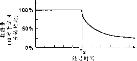
Figure 10 schematically is illustrated in the said method of variable bit rate record in the non-volatile recording pattern, so that according to the spatial capacity of recording medium and the compression ratio that changes digital signal writing time.Here, compression ratio continuously changed according to this time, still, had as above described, and in fact compression ratio is changed between several steps.
In the present embodiment, shown in Figure 10 A, after recording start elapsed time T1, compression ratio is linear the change, and shown in Figure 10 B, also can be from the linear compression ratio that changes of recording start.And, shown in Figure 10 C, also can be after recording start elapsed time T2, by using nonlinear function, for example fractional function, exponential function and logarithmic function change compression ratio, or shown in Figure 10 D, also can change compression ratio by a curve from recording start.
Should be noted that when data compression ratio increased, transfer rate also increased when carrying out above-mentioned compression ratio control, for this reason, most preferably, maximum compression ratio is compressed in 20% of the data volume of recording start data volume.
In the present embodiment, being used to change the said method that writes down bit rate also can be used in combination as required.In addition, also can adopt segment encoding to improve compression ratio practically.Just, in the screen formed of digital signal by input, to the minimizing of the bit number of peripheral part distribution greater than minimizing to core allocation bit data.It is according to as follows.In long-time pattern, compression ratio is quite high and the reproducing signal bit rate is lowered, and usually produces piece distortion and mosquito noise.In order to address this problem, the bit that partly distributes for the screen center of the more important content of common demonstration is more than the screen peripheral part.
Then, will be illustrated at digital signal reproduction method and device according to the embodiment of the invention.
Figure 11 represents the block diagram with respect to the configuration example of the digital signal reproduction device of digital-signal recording apparatus shown in Figure 1.This digital signal reproduction device is used for reproducing such as vision signal of having compressed in above-mentioned high-quality screen pattern or long-time pattern before being recorded on the disc-shape recoding medium 100 and the digital signal the audio signal.In this digital signal reproduction device, the parts identical with parts in the digital-signal recording apparatus of Fig. 1 indicate identical symbol.
The compression digital signal of reading such as vision signal from disc-shape recoding medium 100 by predetermined read-out device is accumulated at the FIFO memory 42, so that be transformed into continuous data, this signal resolves into vision signal, audio signal and companion data in multichannel decomposition circuit 43.This companion data is a control signal that comprises high-quality screen/long-time mode switch signal.Should be noted that above-mentioned read-out device with traditional identical, and omit its explanation.
The vision signal of separating in multichannel decomposition circuit 43 is decoded from compressive state by the compression coding circuit 44 as decoding device, and use according to the parameter that high-quality screen/long-time mode switch signal is selected, stand the post-filtering that is undertaken by postfilter 45.This signal also is transformed into the analog video signal that is used to export by NTSC encoder 46 codings with by D/A converter 47.
On the other hand, the audio signal of having separated at multichannel decomposition circuit 43 is decoded and is used parameter according to high-quality screen/long-time mode switch signal selection to stand the filtering of being undertaken by postfilter 55 from compressive state by compression coding circuit 54.This signal is further encoded by NTSC encoder 56 and is transformed into the simulated audio signal that is used to export by D/A converter 57.
Should be noted that Figure 11 represents the configuration example based on the vision signal specification conditions of NTSC method.Yet, also can adopt different with the NTSC method, the vision signal specification of PAL method and SECAM method for example.In this case, NTSC encoder 46 and 56 usefulness satisfy the encoder replacement of these vision signal specifications.
Figure 12 represents the block diagram of configuration example of the postfilter 45 of Figure 11.
In long-time pattern, the compression ratio of vision signal is set to high value, so that prolong the up duration of video signal recording on disc-shape recoding medium 100.For this reason, piece distortion meeting occurs in the picture that reproduces.This piece distortion at reproduction period by reducing with postfilter 45 filtering.Here, in the field noise minimizing (FNR) that is used for the noise minimizing of every execution of vision signal, a kind of method is arranged, promptly when the difference between the continuous in time field is worth less than certain, carry out subtraction, so that reduce this difference,, make the image variation of the picture of reproduction so alleviated because the great change of piece distortion between the field.This method is implemented in practice.
More specifically, the vision signal of a field or a frame is by compression coding circuit 44 decoding, and accumulation and subtracting each other with next of vision signal or a frame in difference channel 45b in memory 45a is to obtain a difference.This difference is restricted to certain value by restricting circuits 45c or following and deliver to difference channel 45e through attenuator 45d.The attenuation of this attenuator 45d is according to high-quality screen/long-time mode switch signal controlling.In difference channel 45e, subtract each other from difference and the vision signal that provides from compression coding circuit 44 of attenuator 45e, to output to NTSC encoder 46.So, can reduce the piece distortion at reproduction period.
Should be noted that in the present embodiment, in the high-quality screen pattern, realized this setting, make to be not easy to occur the piece distortion, therefore, this FNR seldom carries out or does not carry out fully.This is because be subjected to the picture of FNR standing to shake/make when tilting its thin variation.
Thus, when film with high additive value works thing etc. during with digital signal record, usually will be under the high-quality screen pattern executive logging so that obtain excellent image quality.Should limit or forbid duplicating privately by collecting corresponding expense the works of this kind high picture quality.
Therefore, when under the high-quality screen pattern at the signal of record on the disc-shape recoding medium 100 when the high-quality screen model duplication is on another device or recording medium, preferably, forbid that this duplicates maybe should limit the number of copy operation or collect high cost.On the contrary,, preferably reduce above-mentioned restriction, collect the expense of hanging down any when under long-time pattern, carrying out when duplicating with reducing image quality slightly.
In digit signal record method according to the present invention and device, digital signal is used by the compression ratio of determining by control signal in a plurality of compression ratios and is compressed, therefore, can be on a disc-shape recoding medium of energy recorded video signal at the high-quality screen pattern with different compression ratios and the long-time following video signal recording of pattern.
And, in digital signal reproduction method according to the present invention and device, above-mentioned digit signal record method and device are used to reproduce with different compression ratios and are recorded in a digital signal on the disc-shape recoding medium and this signal through being subject to processing, to reduce the basis piece distortion of compression ratio separately being output before.Therefore, even, also can reproduce with practical image quality under long-time pattern, writing down vision signal with high compression ratio.
Above-mentioned when having when utilizing than the good random access capability of tape and disc-shape recoding medium executive logging that can the high picture quality recoding/reproduction/reproductions, can select to correspond respectively to the high-quality screen pattern of mode standard in VTR and long-time pattern and pattern for a long time.So,, can use emphatically image quality to allow the high-quality screen pattern of short record time and long emphatically long-time pattern of allowing picture quality degradation writing time selectively according to the content of wanting tracer signal.
Claims (19)
1. one kind is used for the digit signal record method of compress and record digital signal on can random-access recording medium (100), and described method comprises:
Separating step is used for separating input analog video signal and companion data from other input analog signal;
First switch process is used for input analog video signal is converted to digital video signal;
Step is provided, is used for described companion data is offered control system (62);
Compression step, be used for compressing described digital video signal by the compression ratio of determining from a plurality of compression ratios from a control signal of described control system (62), described compression step comprises and is used to the conditioning step implementing the discrete cosine transform step of discrete cosine transform and be used to limit the frequency band of digital video signal;
Second switch process, be used for will compression digital video signal be converted to the serial data that has from other other data of drawing of input analog signal;
The accumulation step is used in the described serial data of memory (42) accumulation; With
Recording step is used for the digital signal in the recording areas record accumulation of described recording medium (100).
2. digit signal record method as claimed in claim 1, wherein, if one first pattern that is provided with from described a plurality of compression ratios, to determine first compression ratio, then digital signal is recorded on the recording medium with fixed rate; If with one second pattern that is provided with to determine second compression ratio higher than described first compression ratio, then digital signal is recorded on the recording medium with variable bit rate.
3. digit signal record method as claimed in claim 2, wherein said recording medium has with the recording areas of the first mode record digital signal with the posting field of the second mode record digital signal, and these posting fields are recently determined according to described compression respectively.
4. digit signal record method as claimed in claim 2, wherein said recording medium is a disc-shape recoding medium that has the first record area that is provided on the circumferential periphery and be provided at the second record area on the inner periphery limit, and, if first pattern were set digital signal record described first record area and if second pattern is set then digital signal record at described second record area.
5. digit signal record method as claimed in claim 2, wherein the sampling frequency of digital signal is lower than the sampling frequency of digital signal in described first pattern in described second pattern.
6. digit signal record method as claimed in claim 2, wherein the peak frequency of the digital signal in described second pattern is lower than the peak frequency of the digital signal in described first pattern.
7. digit signal record method as claimed in claim 2, wherein the number of the screen that every unit time is made of continuously digital signal in described second pattern lacks than the number of the screen that is made of continuously digital signal in the time in the unit in described first pattern.
8. digit signal record method as claimed in claim 2, it is littler than constitute the number of pixel of a screen with digital signal in described first pattern wherein to constitute the number of pixel of a screen with digital signal in described second pattern.
9. digit signal record method as claimed in claim 2, wherein the size of the screen that is made of digital signal in described second pattern is than little by the screen size that digital signal constitutes in described first pattern.
10. digit signal record method as claimed in claim 2, wherein in described second pattern, the bit number that reduces to distribute to the peripheral part of a screen has more high priority than reducing the bit number of partly distributing for this screen center when carrying out, described screen is made of digital signal.
11. a digital-signal recording apparatus comprises:
Separator (12) is used for separating input analog video signal and companion data from other input analog signal;
First conversion equipment (14), being used for the input analog signal conversion is digital video signal;
Generator is used for described companion data is offered control system (62);
Compression set (20), be used for compressing described digital video signal by the compression ratio of determining from a plurality of compression ratios from a control signal of described control system (62), described compression set (20) comprises the discrete cosine conversion device (24) that is used to implement discrete cosine transform and is used to limit the restraint device (25) of the frequency band of digital video signal;
Second conversion equipment (41), be used for will compression digital video signal be converted to the serial data that has from other other data of drawing of input analog signal;
Memory (42) is used to accumulate this serial data; With
Tape deck is used for the digital signal record of accumulation is gone up according to described compression ratio from the recording areas that a plurality of recording areas are determined at recording medium (100).
12. digital-signal recording apparatus as claimed in claim 11, described device also comprises the complexity checkout gear, is used to detect the complexity of described digital signal, so that change the compression ratio of described digital signal according to the complexity that detects.
13. digital-signal recording apparatus as claimed in claim 11, wherein said compression set is according to the companion data conversion compression ratio of the signal specification and the expression input signal content of input signal.
14. being one, digital-signal recording apparatus as claimed in claim 11, wherein said recording medium have the disc-shape recoding medium that is used to write down digital signal at the second record area on outer circumferential sides of the first record area of inner circumferential side and the digital signal that to be used to write down its compression ratio lower than the compression ratio that is recorded in digital signal on the described first record area.
15. one kind is used to reproduce and is recorded in the digital signal reproduction method that can pass through according to the compression digital signal on the random-access recording medium of the method for claim 1 (100), described reproducting method comprises:
Reading step is used to read the digital signal with the compression ratio that changes according to the recording areas of described recording medium (100);
The accumulation step is used for the reading number signal accumulation in memory (42);
Separating step is used for separating digital video signal by the accumulation of discrete cosine transform compression from the digital signal of other accumulation of comprising the companion data of representing each compression ratio; With
The compression coding step is used to use the parameter that relies on companion data, the digital video signal of compression coding accumulation.
16. digital signal reproduction method as claimed in claim 15, wherein said recording medium are the recording mediums of dish type.
17. a digital signal reproduction device comprises:
Read-out device is used for reading the digital signal that is recorded in the different recording regions of the random-access recording medium of energy (100) with different compression ratios by the recording method according to claim 1;
Memory (42) is used to accumulate the digital signal of reading;
Separator (43) is used for separating digital video signal by the accumulation of discrete cosine transform compression from the digital signal of other accumulation of comprising the companion data of representing each compression ratio; With
Compression coding device (44) is used to use the parameter that relies on companion data, the digital video signal of compression coding accumulation.
18. digital signal reproduction device as claimed in claim 17, wherein said decoding device comprises:
Memory (45a) is used to accumulate the pictures that is made of the digital video signal of decoding;
Difference channel (45b) is used to obtain the difference video signal between the pictures of current picture that the digital video signal by decoding constitutes and described accumulation;
Signal limitations device (45c) is used to limit the frequency band and the amplitude of described difference video signal; With
Filter with substracting unit (45e) is used for deducting the signal with restricted band and amplitude from the digital video signal of decoding according to compression ratio.
19. digital signal reproduction device as claimed in claim 17, wherein said recording medium are the recording mediums of a dish type.
Applications Claiming Priority (3)
| Application Number | Priority Date | Filing Date | Title |
|---|---|---|---|
| JP9032424A JPH10228728A (en) | 1997-02-17 | 1997-02-17 | Digital signal recording method and device therefor digital signal reproduction method and device therefor |
| JP032424/97 | 1997-02-17 | ||
| JP032424/1997 | 1997-02-17 |
Publications (2)
| Publication Number | Publication Date |
|---|---|
| CN1198066A CN1198066A (en) | 1998-11-04 |
| CN1178528C true CN1178528C (en) | 2004-12-01 |
Family
ID=12358582
Family Applications (1)
| Application Number | Title | Priority Date | Filing Date |
|---|---|---|---|
| CNB981082815A Expired - Lifetime CN1178528C (en) | 1997-02-17 | 1998-02-17 | Digital signal recording method and apparatus and digital signal reproduction method and apparatus |
Country Status (7)
| Country | Link |
|---|---|
| US (1) | US6115341A (en) |
| EP (1) | EP0859523B1 (en) |
| JP (1) | JPH10228728A (en) |
| KR (1) | KR19980071371A (en) |
| CN (1) | CN1178528C (en) |
| DE (1) | DE69813343T2 (en) |
| ES (1) | ES2192742T3 (en) |
Families Citing this family (53)
| Publication number | Priority date | Publication date | Assignee | Title |
|---|---|---|---|---|
| AU7935198A (en) * | 1997-07-01 | 1999-01-25 | Sanyo Electric Co., Ltd. | Recording medium, recorder, and player |
| SG82587A1 (en) * | 1997-10-21 | 2001-08-21 | Sony Corp | Recording apparatus, recording method, playback apparatus, playback method, recording/playback apparatus, recording/playback method, presentation medium and recording medium |
| TW385436B (en) | 1997-12-12 | 2000-03-21 | Toshiba Corp | Digital recording system using variable recording rate |
| JP4182369B2 (en) * | 1998-05-29 | 2008-11-19 | ソニー株式会社 | Recording / reproducing apparatus and method, and recording medium |
| JP2000101658A (en) * | 1998-09-24 | 2000-04-07 | Victor Co Of Japan Ltd | Interface circuit |
| TWI222627B (en) * | 1998-10-27 | 2004-10-21 | Hitachi Maxell | Information recording method and system, image compression/decompression system, system control method and monitoring system including a part or all of the method |
| US6205499B1 (en) * | 1998-12-18 | 2001-03-20 | The United States Of America As Represented By The Secretary Of The Navy | System for compressing video data using bi-orthogonal wavelet coding having a DSP for adjusting compression ratios to maintain a constant data flow rate of the compressed data |
| US6564005B1 (en) | 1999-01-28 | 2003-05-13 | International Business Machines Corporation | Multi-user video hard disk recorder |
| SE522856C2 (en) * | 1999-01-29 | 2004-03-09 | Axis Ab | A data storage and reduction method for digital images, as well as a monitoring system using said method |
| KR100324746B1 (en) * | 1999-04-24 | 2002-02-20 | 구자홍 | Digital data player capable of voice hearing |
| JP4489248B2 (en) * | 1999-06-02 | 2010-06-23 | パナソニック株式会社 | Optical disk, apparatus and method for recording / reproducing data on / from optical disk |
| US6504995B1 (en) * | 1999-07-21 | 2003-01-07 | Hewlett-Packard Company | Apparatus and method for storing compressed data to a storage device |
| JP4004695B2 (en) * | 1999-10-04 | 2007-11-07 | パイオニア株式会社 | Information recording device |
| JP4501187B2 (en) | 1999-10-22 | 2010-07-14 | ソニー株式会社 | Information processing apparatus, information processing system, and information processing method |
| EP1104196A3 (en) * | 1999-11-09 | 2004-06-16 | Denon, Ltd. | Device for data compression and storage |
| US6741650B1 (en) | 2000-03-02 | 2004-05-25 | Adc Telecommunications, Inc. | Architecture for intermediate frequency encoder |
| US6766100B1 (en) * | 2000-10-19 | 2004-07-20 | Ati International Srl | Method and apparatus for multi-TV tuner display of video information |
| US20020136538A1 (en) * | 2001-03-22 | 2002-09-26 | Koninklijke Philips Electronics N.V. | Smart quality setting for personal TV recording |
| KR20030007711A (en) * | 2001-03-26 | 2003-01-23 | 코닌클리케 필립스 일렉트로닉스 엔.브이. | Storage of multi-media items |
| JP2003199045A (en) * | 2001-12-26 | 2003-07-11 | Victor Co Of Japan Ltd | Information-recording-signal generating method and apparatus, information-signal reproducing method and apparatus, information-signal transmitting method, apparatus and program, and information-signal recording medium |
| US6993285B2 (en) * | 2002-04-11 | 2006-01-31 | International Business Machines Corporation | Audio buffer processing |
| JP4162454B2 (en) * | 2002-09-10 | 2008-10-08 | 三洋電機株式会社 | Data processing device |
| JP3712204B2 (en) * | 2002-10-31 | 2005-11-02 | ソニー株式会社 | Recording / playback device |
| KR20040104237A (en) * | 2003-06-03 | 2004-12-10 | 삼성전자주식회사 | Photograping apparatus and method which sets compression format automatically |
| JP2005033622A (en) * | 2003-07-08 | 2005-02-03 | Matsushita Electric Ind Co Ltd | Apparatus and method for video signal recording |
| JP4101780B2 (en) * | 2004-03-22 | 2008-06-18 | 株式会社日立国際電気 | Signal transmission method and signal transmission apparatus |
| US9082456B2 (en) | 2005-01-31 | 2015-07-14 | The Invention Science Fund I Llc | Shared image device designation |
| US7920169B2 (en) | 2005-01-31 | 2011-04-05 | Invention Science Fund I, Llc | Proximity of shared image devices |
| US20060174203A1 (en) | 2005-01-31 | 2006-08-03 | Searete Llc, A Limited Liability Corporation Of The State Of Delaware | Viewfinder for shared image device |
| US9489717B2 (en) | 2005-01-31 | 2016-11-08 | Invention Science Fund I, Llc | Shared image device |
| US7876357B2 (en) | 2005-01-31 | 2011-01-25 | The Invention Science Fund I, Llc | Estimating shared image device operational capabilities or resources |
| US20060170956A1 (en) | 2005-01-31 | 2006-08-03 | Jung Edward K | Shared image devices |
| US9124729B2 (en) | 2005-01-31 | 2015-09-01 | The Invention Science Fund I, Llc | Shared image device synchronization or designation |
| US8902320B2 (en) | 2005-01-31 | 2014-12-02 | The Invention Science Fund I, Llc | Shared image device synchronization or designation |
| US9910341B2 (en) | 2005-01-31 | 2018-03-06 | The Invention Science Fund I, Llc | Shared image device designation |
| US8606383B2 (en) | 2005-01-31 | 2013-12-10 | The Invention Science Fund I, Llc | Audio sharing |
| US9325781B2 (en) | 2005-01-31 | 2016-04-26 | Invention Science Fund I, Llc | Audio sharing |
| US9001215B2 (en) | 2005-06-02 | 2015-04-07 | The Invention Science Fund I, Llc | Estimating shared image device operational capabilities or resources |
| US9942511B2 (en) | 2005-10-31 | 2018-04-10 | Invention Science Fund I, Llc | Preservation/degradation of video/audio aspects of a data stream |
| US10003762B2 (en) | 2005-04-26 | 2018-06-19 | Invention Science Fund I, Llc | Shared image devices |
| US7782365B2 (en) | 2005-06-02 | 2010-08-24 | Searete Llc | Enhanced video/still image correlation |
| US9093121B2 (en) | 2006-02-28 | 2015-07-28 | The Invention Science Fund I, Llc | Data management of an audio data stream |
| US9819490B2 (en) | 2005-05-04 | 2017-11-14 | Invention Science Fund I, Llc | Regional proximity for shared image device(s) |
| US9451200B2 (en) | 2005-06-02 | 2016-09-20 | Invention Science Fund I, Llc | Storage access technique for captured data |
| US9967424B2 (en) | 2005-06-02 | 2018-05-08 | Invention Science Fund I, Llc | Data storage usage protocol |
| US8681225B2 (en) | 2005-06-02 | 2014-03-25 | Royce A. Levien | Storage access technique for captured data |
| JP4769695B2 (en) * | 2005-12-16 | 2011-09-07 | キヤノン株式会社 | Imaging device and playback device |
| CN100591111C (en) * | 2005-12-16 | 2010-02-17 | 佳能株式会社 | Image pickup apparatus, image pickup method, reproducing apparatus and reproducing method |
| JP2009100461A (en) * | 2007-09-28 | 2009-05-07 | Sanyo Electric Co Ltd | Video recording and reproducing device, video recording device and video encoding device |
| JP4565358B2 (en) * | 2008-07-01 | 2010-10-20 | ソニー株式会社 | Editing apparatus and editing method |
| CN101931773A (en) * | 2009-06-23 | 2010-12-29 | 虹软(杭州)多媒体信息技术有限公司 | Video processing method |
| CN102169134A (en) * | 2010-12-17 | 2011-08-31 | 中国电力科学研究院 | A hardware-based transient voltage recording method |
| US9313300B2 (en) * | 2013-11-07 | 2016-04-12 | Integrated Device Technology, Inc. | Methods and apparatuses for a unified compression framework of baseband signals |
Family Cites Families (7)
| Publication number | Priority date | Publication date | Assignee | Title |
|---|---|---|---|---|
| JP3141241B2 (en) * | 1990-08-24 | 2001-03-05 | ソニー株式会社 | Disk recording device and disk reproducing device |
| JP2507174B2 (en) * | 1990-11-20 | 1996-06-12 | 松下電器産業株式会社 | Optical disk drive |
| KR100289855B1 (en) * | 1993-07-12 | 2001-05-15 | 이데이 노부유끼 | Decryption method and apparatus |
| JPH087478A (en) * | 1994-06-20 | 1996-01-12 | Pioneer Video Corp | Compressed picture information recorder |
| DE69533810T2 (en) * | 1994-09-26 | 2005-12-15 | Matsushita Electric Industrial Co., Ltd., Kadoma | Recording device for digital signals |
| MY114287A (en) * | 1994-12-26 | 2002-09-30 | Sony Corp | Digital video recorder |
| JP3774914B2 (en) * | 1995-09-27 | 2006-05-17 | ソニー株式会社 | Video equipment |
-
1997
- 1997-02-17 JP JP9032424A patent/JPH10228728A/en active Pending
-
1998
- 1998-02-09 US US09/020,691 patent/US6115341A/en not_active Expired - Lifetime
- 1998-02-10 DE DE69813343T patent/DE69813343T2/en not_active Expired - Lifetime
- 1998-02-10 EP EP98300963A patent/EP0859523B1/en not_active Expired - Lifetime
- 1998-02-10 ES ES98300963T patent/ES2192742T3/en not_active Expired - Lifetime
- 1998-02-16 KR KR1019980004516A patent/KR19980071371A/en active Search and Examination
- 1998-02-17 CN CNB981082815A patent/CN1178528C/en not_active Expired - Lifetime
Also Published As
| Publication number | Publication date |
|---|---|
| EP0859523A2 (en) | 1998-08-19 |
| EP0859523B1 (en) | 2003-04-16 |
| US6115341A (en) | 2000-09-05 |
| KR19980071371A (en) | 1998-10-26 |
| CN1198066A (en) | 1998-11-04 |
| EP0859523A3 (en) | 2000-04-19 |
| DE69813343T2 (en) | 2004-02-12 |
| DE69813343D1 (en) | 2003-05-22 |
| ES2192742T3 (en) | 2003-10-16 |
| JPH10228728A (en) | 1998-08-25 |
Similar Documents
| Publication | Publication Date | Title |
|---|---|---|
| CN1178528C (en) | Digital signal recording method and apparatus and digital signal reproduction method and apparatus | |
| CN1151682C (en) | Video transmission apparatus employing intra-frame-only video compression that is MPEG-2 compatible | |
| KR100267036B1 (en) | Image prcessing device | |
| CN1089526C (en) | Digital recording and reproducing apparatus | |
| CN1127852C (en) | Wide-band multi-format audio/video prodn system with frame-rate conversion | |
| CN1073780C (en) | Television-integated video cassette recorder apparatus | |
| CN1180633C (en) | Arrangement and method for processing video data | |
| CN1808564A (en) | Apparatus for adjusting display size and method thereof | |
| CN1246644A (en) | Digital camera device and recording method thereof | |
| CN1149922A (en) | Digital VCR with non-standard speed playback | |
| CN1206987A (en) | Video frequency device, display method, record method and reproducing method | |
| CN101969557B (en) | Image recording device, and image recording method | |
| CN1798348A (en) | Personal video recorder system and method for reproducing a signal in the system | |
| CN1138413C (en) | Digital recording and reproducing apparatus | |
| JPH0865663A (en) | Digital image information processor | |
| CN1192630C (en) | Data transmitting device and method, recording device and recording/reproducing device | |
| CN1668098A (en) | Optical recording/reproducing apparatus having a function of separating luminance and color components | |
| WO1998037558A2 (en) | Method of and arrangement for recording and reproducing video images | |
| EP0772366A2 (en) | A digital recording/reproducing apparatus | |
| JP2005237020A (en) | Digital video processing apparatus and method | |
| KR20040078488A (en) | Method for record/reproducing of Image display device | |
| JPH07274114A (en) | Method and device for reproducing digitally compressed dynamic image at high speed | |
| EP0985212A2 (en) | Method of and arrangement for recording and reproducing video images | |
| JPH0342556B2 (en) |
Legal Events
| Date | Code | Title | Description |
|---|---|---|---|
| C06 | Publication | ||
| PB01 | Publication | ||
| C10 | Entry into substantive examination | ||
| SE01 | Entry into force of request for substantive examination | ||
| C14 | Grant of patent or utility model | ||
| GR01 | Patent grant | ||
| CX01 | Expiry of patent term | ||
| CX01 | Expiry of patent term |
Granted publication date: 20041201 |