CN1174399C - Optical information record medium - Google Patents
Optical information record medium Download PDFInfo
- Publication number
- CN1174399C CN1174399C CNB991248953A CN99124895A CN1174399C CN 1174399 C CN1174399 C CN 1174399C CN B991248953 A CNB991248953 A CN B991248953A CN 99124895 A CN99124895 A CN 99124895A CN 1174399 C CN1174399 C CN 1174399C
- Authority
- CN
- China
- Prior art keywords
- medium
- layer
- recording medium
- thermal diffusion
- optical data
- Prior art date
- Legal status (The legal status is an assumption and is not a legal conclusion. Google has not performed a legal analysis and makes no representation as to the accuracy of the status listed.)
- Expired - Lifetime
Links
Images


Classifications
-
- G—PHYSICS
- G11—INFORMATION STORAGE
- G11B—INFORMATION STORAGE BASED ON RELATIVE MOVEMENT BETWEEN RECORD CARRIER AND TRANSDUCER
- G11B7/00—Recording or reproducing by optical means, e.g. recording using a thermal beam of optical radiation by modifying optical properties or the physical structure, reproducing using an optical beam at lower power by sensing optical properties; Record carriers therefor
- G11B7/24—Record carriers characterised by shape, structure or physical properties, or by the selection of the material
- G11B7/2403—Layers; Shape, structure or physical properties thereof
-
- G—PHYSICS
- G11—INFORMATION STORAGE
- G11B—INFORMATION STORAGE BASED ON RELATIVE MOVEMENT BETWEEN RECORD CARRIER AND TRANSDUCER
- G11B7/00—Recording or reproducing by optical means, e.g. recording using a thermal beam of optical radiation by modifying optical properties or the physical structure, reproducing using an optical beam at lower power by sensing optical properties; Record carriers therefor
- G11B7/24—Record carriers characterised by shape, structure or physical properties, or by the selection of the material
- G11B7/241—Record carriers characterised by shape, structure or physical properties, or by the selection of the material characterised by the selection of the material
- G11B7/252—Record carriers characterised by shape, structure or physical properties, or by the selection of the material characterised by the selection of the material of layers other than recording layers
- G11B7/254—Record carriers characterised by shape, structure or physical properties, or by the selection of the material characterised by the selection of the material of layers other than recording layers of protective topcoat layers
- G11B7/2548—Record carriers characterised by shape, structure or physical properties, or by the selection of the material characterised by the selection of the material of layers other than recording layers of protective topcoat layers consisting essentially of inorganic materials
-
- G—PHYSICS
- G11—INFORMATION STORAGE
- G11B—INFORMATION STORAGE BASED ON RELATIVE MOVEMENT BETWEEN RECORD CARRIER AND TRANSDUCER
- G11B7/00—Recording or reproducing by optical means, e.g. recording using a thermal beam of optical radiation by modifying optical properties or the physical structure, reproducing using an optical beam at lower power by sensing optical properties; Record carriers therefor
- G11B7/24—Record carriers characterised by shape, structure or physical properties, or by the selection of the material
- G11B7/241—Record carriers characterised by shape, structure or physical properties, or by the selection of the material characterised by the selection of the material
- G11B7/242—Record carriers characterised by shape, structure or physical properties, or by the selection of the material characterised by the selection of the material of recording layers
- G11B7/243—Record carriers characterised by shape, structure or physical properties, or by the selection of the material characterised by the selection of the material of recording layers comprising inorganic materials only, e.g. ablative layers
- G11B2007/24302—Metals or metalloids
- G11B2007/24304—Metals or metalloids group 2 or 12 elements (e.g. Be, Ca, Mg, Zn, Cd)
-
- G—PHYSICS
- G11—INFORMATION STORAGE
- G11B—INFORMATION STORAGE BASED ON RELATIVE MOVEMENT BETWEEN RECORD CARRIER AND TRANSDUCER
- G11B7/00—Recording or reproducing by optical means, e.g. recording using a thermal beam of optical radiation by modifying optical properties or the physical structure, reproducing using an optical beam at lower power by sensing optical properties; Record carriers therefor
- G11B7/24—Record carriers characterised by shape, structure or physical properties, or by the selection of the material
- G11B7/241—Record carriers characterised by shape, structure or physical properties, or by the selection of the material characterised by the selection of the material
- G11B7/242—Record carriers characterised by shape, structure or physical properties, or by the selection of the material characterised by the selection of the material of recording layers
- G11B7/243—Record carriers characterised by shape, structure or physical properties, or by the selection of the material characterised by the selection of the material of recording layers comprising inorganic materials only, e.g. ablative layers
- G11B2007/24302—Metals or metalloids
- G11B2007/24308—Metals or metalloids transition metal elements of group 11 (Cu, Ag, Au)
-
- G—PHYSICS
- G11—INFORMATION STORAGE
- G11B—INFORMATION STORAGE BASED ON RELATIVE MOVEMENT BETWEEN RECORD CARRIER AND TRANSDUCER
- G11B7/00—Recording or reproducing by optical means, e.g. recording using a thermal beam of optical radiation by modifying optical properties or the physical structure, reproducing using an optical beam at lower power by sensing optical properties; Record carriers therefor
- G11B7/24—Record carriers characterised by shape, structure or physical properties, or by the selection of the material
- G11B7/241—Record carriers characterised by shape, structure or physical properties, or by the selection of the material characterised by the selection of the material
- G11B7/242—Record carriers characterised by shape, structure or physical properties, or by the selection of the material characterised by the selection of the material of recording layers
- G11B7/243—Record carriers characterised by shape, structure or physical properties, or by the selection of the material characterised by the selection of the material of recording layers comprising inorganic materials only, e.g. ablative layers
- G11B2007/24302—Metals or metalloids
- G11B2007/2431—Metals or metalloids group 13 elements (B, Al, Ga, In)
-
- G—PHYSICS
- G11—INFORMATION STORAGE
- G11B—INFORMATION STORAGE BASED ON RELATIVE MOVEMENT BETWEEN RECORD CARRIER AND TRANSDUCER
- G11B7/00—Recording or reproducing by optical means, e.g. recording using a thermal beam of optical radiation by modifying optical properties or the physical structure, reproducing using an optical beam at lower power by sensing optical properties; Record carriers therefor
- G11B7/24—Record carriers characterised by shape, structure or physical properties, or by the selection of the material
- G11B7/241—Record carriers characterised by shape, structure or physical properties, or by the selection of the material characterised by the selection of the material
- G11B7/242—Record carriers characterised by shape, structure or physical properties, or by the selection of the material characterised by the selection of the material of recording layers
- G11B7/243—Record carriers characterised by shape, structure or physical properties, or by the selection of the material characterised by the selection of the material of recording layers comprising inorganic materials only, e.g. ablative layers
- G11B2007/24302—Metals or metalloids
- G11B2007/24312—Metals or metalloids group 14 elements (e.g. Si, Ge, Sn)
-
- G—PHYSICS
- G11—INFORMATION STORAGE
- G11B—INFORMATION STORAGE BASED ON RELATIVE MOVEMENT BETWEEN RECORD CARRIER AND TRANSDUCER
- G11B7/00—Recording or reproducing by optical means, e.g. recording using a thermal beam of optical radiation by modifying optical properties or the physical structure, reproducing using an optical beam at lower power by sensing optical properties; Record carriers therefor
- G11B7/24—Record carriers characterised by shape, structure or physical properties, or by the selection of the material
- G11B7/241—Record carriers characterised by shape, structure or physical properties, or by the selection of the material characterised by the selection of the material
- G11B7/242—Record carriers characterised by shape, structure or physical properties, or by the selection of the material characterised by the selection of the material of recording layers
- G11B7/243—Record carriers characterised by shape, structure or physical properties, or by the selection of the material characterised by the selection of the material of recording layers comprising inorganic materials only, e.g. ablative layers
- G11B2007/24302—Metals or metalloids
- G11B2007/24314—Metals or metalloids group 15 elements (e.g. Sb, Bi)
-
- G—PHYSICS
- G11—INFORMATION STORAGE
- G11B—INFORMATION STORAGE BASED ON RELATIVE MOVEMENT BETWEEN RECORD CARRIER AND TRANSDUCER
- G11B7/00—Recording or reproducing by optical means, e.g. recording using a thermal beam of optical radiation by modifying optical properties or the physical structure, reproducing using an optical beam at lower power by sensing optical properties; Record carriers therefor
- G11B7/24—Record carriers characterised by shape, structure or physical properties, or by the selection of the material
- G11B7/241—Record carriers characterised by shape, structure or physical properties, or by the selection of the material characterised by the selection of the material
- G11B7/242—Record carriers characterised by shape, structure or physical properties, or by the selection of the material characterised by the selection of the material of recording layers
- G11B7/243—Record carriers characterised by shape, structure or physical properties, or by the selection of the material characterised by the selection of the material of recording layers comprising inorganic materials only, e.g. ablative layers
- G11B2007/24302—Metals or metalloids
- G11B2007/24316—Metals or metalloids group 16 elements (i.e. chalcogenides, Se, Te)
-
- G—PHYSICS
- G11—INFORMATION STORAGE
- G11B—INFORMATION STORAGE BASED ON RELATIVE MOVEMENT BETWEEN RECORD CARRIER AND TRANSDUCER
- G11B7/00—Recording or reproducing by optical means, e.g. recording using a thermal beam of optical radiation by modifying optical properties or the physical structure, reproducing using an optical beam at lower power by sensing optical properties; Record carriers therefor
- G11B7/24—Record carriers characterised by shape, structure or physical properties, or by the selection of the material
- G11B7/241—Record carriers characterised by shape, structure or physical properties, or by the selection of the material characterised by the selection of the material
- G11B7/252—Record carriers characterised by shape, structure or physical properties, or by the selection of the material characterised by the selection of the material of layers other than recording layers
- G11B7/254—Record carriers characterised by shape, structure or physical properties, or by the selection of the material characterised by the selection of the material of layers other than recording layers of protective topcoat layers
- G11B2007/25408—Record carriers characterised by shape, structure or physical properties, or by the selection of the material characterised by the selection of the material of layers other than recording layers of protective topcoat layers consisting essentially of inorganic materials
- G11B2007/25411—Record carriers characterised by shape, structure or physical properties, or by the selection of the material characterised by the selection of the material of layers other than recording layers of protective topcoat layers consisting essentially of inorganic materials containing transition metal elements (Zn, Fe, Co, Ni, Pt)
-
- G—PHYSICS
- G11—INFORMATION STORAGE
- G11B—INFORMATION STORAGE BASED ON RELATIVE MOVEMENT BETWEEN RECORD CARRIER AND TRANSDUCER
- G11B7/00—Recording or reproducing by optical means, e.g. recording using a thermal beam of optical radiation by modifying optical properties or the physical structure, reproducing using an optical beam at lower power by sensing optical properties; Record carriers therefor
- G11B7/24—Record carriers characterised by shape, structure or physical properties, or by the selection of the material
- G11B7/241—Record carriers characterised by shape, structure or physical properties, or by the selection of the material characterised by the selection of the material
- G11B7/252—Record carriers characterised by shape, structure or physical properties, or by the selection of the material characterised by the selection of the material of layers other than recording layers
- G11B7/254—Record carriers characterised by shape, structure or physical properties, or by the selection of the material characterised by the selection of the material of layers other than recording layers of protective topcoat layers
- G11B2007/25408—Record carriers characterised by shape, structure or physical properties, or by the selection of the material characterised by the selection of the material of layers other than recording layers of protective topcoat layers consisting essentially of inorganic materials
- G11B2007/25414—Record carriers characterised by shape, structure or physical properties, or by the selection of the material characterised by the selection of the material of layers other than recording layers of protective topcoat layers consisting essentially of inorganic materials containing Group 13 elements (B, Al, Ga)
-
- G—PHYSICS
- G11—INFORMATION STORAGE
- G11B—INFORMATION STORAGE BASED ON RELATIVE MOVEMENT BETWEEN RECORD CARRIER AND TRANSDUCER
- G11B7/00—Recording or reproducing by optical means, e.g. recording using a thermal beam of optical radiation by modifying optical properties or the physical structure, reproducing using an optical beam at lower power by sensing optical properties; Record carriers therefor
- G11B7/24—Record carriers characterised by shape, structure or physical properties, or by the selection of the material
- G11B7/241—Record carriers characterised by shape, structure or physical properties, or by the selection of the material characterised by the selection of the material
- G11B7/252—Record carriers characterised by shape, structure or physical properties, or by the selection of the material characterised by the selection of the material of layers other than recording layers
- G11B7/254—Record carriers characterised by shape, structure or physical properties, or by the selection of the material characterised by the selection of the material of layers other than recording layers of protective topcoat layers
- G11B2007/25408—Record carriers characterised by shape, structure or physical properties, or by the selection of the material characterised by the selection of the material of layers other than recording layers of protective topcoat layers consisting essentially of inorganic materials
- G11B2007/25417—Record carriers characterised by shape, structure or physical properties, or by the selection of the material characterised by the selection of the material of layers other than recording layers of protective topcoat layers consisting essentially of inorganic materials containing Group 14 elements (C, Si, Ge, Sn)
-
- G—PHYSICS
- G11—INFORMATION STORAGE
- G11B—INFORMATION STORAGE BASED ON RELATIVE MOVEMENT BETWEEN RECORD CARRIER AND TRANSDUCER
- G11B7/00—Recording or reproducing by optical means, e.g. recording using a thermal beam of optical radiation by modifying optical properties or the physical structure, reproducing using an optical beam at lower power by sensing optical properties; Record carriers therefor
- G11B7/24—Record carriers characterised by shape, structure or physical properties, or by the selection of the material
- G11B7/241—Record carriers characterised by shape, structure or physical properties, or by the selection of the material characterised by the selection of the material
- G11B7/252—Record carriers characterised by shape, structure or physical properties, or by the selection of the material characterised by the selection of the material of layers other than recording layers
- G11B7/257—Record carriers characterised by shape, structure or physical properties, or by the selection of the material characterised by the selection of the material of layers other than recording layers of layers having properties involved in recording or reproduction, e.g. optical interference layers or sensitising layers or dielectric layers, which are protecting the recording layers
- G11B2007/25705—Record carriers characterised by shape, structure or physical properties, or by the selection of the material characterised by the selection of the material of layers other than recording layers of layers having properties involved in recording or reproduction, e.g. optical interference layers or sensitising layers or dielectric layers, which are protecting the recording layers consisting essentially of inorganic materials
- G11B2007/25706—Record carriers characterised by shape, structure or physical properties, or by the selection of the material characterised by the selection of the material of layers other than recording layers of layers having properties involved in recording or reproduction, e.g. optical interference layers or sensitising layers or dielectric layers, which are protecting the recording layers consisting essentially of inorganic materials containing transition metal elements (Zn, Fe, Co, Ni, Pt)
-
- G—PHYSICS
- G11—INFORMATION STORAGE
- G11B—INFORMATION STORAGE BASED ON RELATIVE MOVEMENT BETWEEN RECORD CARRIER AND TRANSDUCER
- G11B7/00—Recording or reproducing by optical means, e.g. recording using a thermal beam of optical radiation by modifying optical properties or the physical structure, reproducing using an optical beam at lower power by sensing optical properties; Record carriers therefor
- G11B7/24—Record carriers characterised by shape, structure or physical properties, or by the selection of the material
- G11B7/241—Record carriers characterised by shape, structure or physical properties, or by the selection of the material characterised by the selection of the material
- G11B7/252—Record carriers characterised by shape, structure or physical properties, or by the selection of the material characterised by the selection of the material of layers other than recording layers
- G11B7/257—Record carriers characterised by shape, structure or physical properties, or by the selection of the material characterised by the selection of the material of layers other than recording layers of layers having properties involved in recording or reproduction, e.g. optical interference layers or sensitising layers or dielectric layers, which are protecting the recording layers
- G11B2007/25705—Record carriers characterised by shape, structure or physical properties, or by the selection of the material characterised by the selection of the material of layers other than recording layers of layers having properties involved in recording or reproduction, e.g. optical interference layers or sensitising layers or dielectric layers, which are protecting the recording layers consisting essentially of inorganic materials
- G11B2007/25708—Record carriers characterised by shape, structure or physical properties, or by the selection of the material characterised by the selection of the material of layers other than recording layers of layers having properties involved in recording or reproduction, e.g. optical interference layers or sensitising layers or dielectric layers, which are protecting the recording layers consisting essentially of inorganic materials containing group 13 elements (B, Al, Ga)
-
- G—PHYSICS
- G11—INFORMATION STORAGE
- G11B—INFORMATION STORAGE BASED ON RELATIVE MOVEMENT BETWEEN RECORD CARRIER AND TRANSDUCER
- G11B7/00—Recording or reproducing by optical means, e.g. recording using a thermal beam of optical radiation by modifying optical properties or the physical structure, reproducing using an optical beam at lower power by sensing optical properties; Record carriers therefor
- G11B7/24—Record carriers characterised by shape, structure or physical properties, or by the selection of the material
- G11B7/241—Record carriers characterised by shape, structure or physical properties, or by the selection of the material characterised by the selection of the material
- G11B7/252—Record carriers characterised by shape, structure or physical properties, or by the selection of the material characterised by the selection of the material of layers other than recording layers
- G11B7/257—Record carriers characterised by shape, structure or physical properties, or by the selection of the material characterised by the selection of the material of layers other than recording layers of layers having properties involved in recording or reproduction, e.g. optical interference layers or sensitising layers or dielectric layers, which are protecting the recording layers
- G11B2007/25705—Record carriers characterised by shape, structure or physical properties, or by the selection of the material characterised by the selection of the material of layers other than recording layers of layers having properties involved in recording or reproduction, e.g. optical interference layers or sensitising layers or dielectric layers, which are protecting the recording layers consisting essentially of inorganic materials
- G11B2007/2571—Record carriers characterised by shape, structure or physical properties, or by the selection of the material characterised by the selection of the material of layers other than recording layers of layers having properties involved in recording or reproduction, e.g. optical interference layers or sensitising layers or dielectric layers, which are protecting the recording layers consisting essentially of inorganic materials containing group 14 elements except carbon (Si, Ge, Sn, Pb)
-
- G—PHYSICS
- G11—INFORMATION STORAGE
- G11B—INFORMATION STORAGE BASED ON RELATIVE MOVEMENT BETWEEN RECORD CARRIER AND TRANSDUCER
- G11B7/00—Recording or reproducing by optical means, e.g. recording using a thermal beam of optical radiation by modifying optical properties or the physical structure, reproducing using an optical beam at lower power by sensing optical properties; Record carriers therefor
- G11B7/24—Record carriers characterised by shape, structure or physical properties, or by the selection of the material
- G11B7/241—Record carriers characterised by shape, structure or physical properties, or by the selection of the material characterised by the selection of the material
- G11B7/252—Record carriers characterised by shape, structure or physical properties, or by the selection of the material characterised by the selection of the material of layers other than recording layers
- G11B7/257—Record carriers characterised by shape, structure or physical properties, or by the selection of the material characterised by the selection of the material of layers other than recording layers of layers having properties involved in recording or reproduction, e.g. optical interference layers or sensitising layers or dielectric layers, which are protecting the recording layers
- G11B2007/25705—Record carriers characterised by shape, structure or physical properties, or by the selection of the material characterised by the selection of the material of layers other than recording layers of layers having properties involved in recording or reproduction, e.g. optical interference layers or sensitising layers or dielectric layers, which are protecting the recording layers consisting essentially of inorganic materials
- G11B2007/25711—Record carriers characterised by shape, structure or physical properties, or by the selection of the material characterised by the selection of the material of layers other than recording layers of layers having properties involved in recording or reproduction, e.g. optical interference layers or sensitising layers or dielectric layers, which are protecting the recording layers consisting essentially of inorganic materials containing carbon
-
- G—PHYSICS
- G11—INFORMATION STORAGE
- G11B—INFORMATION STORAGE BASED ON RELATIVE MOVEMENT BETWEEN RECORD CARRIER AND TRANSDUCER
- G11B7/00—Recording or reproducing by optical means, e.g. recording using a thermal beam of optical radiation by modifying optical properties or the physical structure, reproducing using an optical beam at lower power by sensing optical properties; Record carriers therefor
- G11B7/24—Record carriers characterised by shape, structure or physical properties, or by the selection of the material
- G11B7/241—Record carriers characterised by shape, structure or physical properties, or by the selection of the material characterised by the selection of the material
- G11B7/252—Record carriers characterised by shape, structure or physical properties, or by the selection of the material characterised by the selection of the material of layers other than recording layers
- G11B7/257—Record carriers characterised by shape, structure or physical properties, or by the selection of the material characterised by the selection of the material of layers other than recording layers of layers having properties involved in recording or reproduction, e.g. optical interference layers or sensitising layers or dielectric layers, which are protecting the recording layers
- G11B2007/25705—Record carriers characterised by shape, structure or physical properties, or by the selection of the material characterised by the selection of the material of layers other than recording layers of layers having properties involved in recording or reproduction, e.g. optical interference layers or sensitising layers or dielectric layers, which are protecting the recording layers consisting essentially of inorganic materials
- G11B2007/25713—Record carriers characterised by shape, structure or physical properties, or by the selection of the material characterised by the selection of the material of layers other than recording layers of layers having properties involved in recording or reproduction, e.g. optical interference layers or sensitising layers or dielectric layers, which are protecting the recording layers consisting essentially of inorganic materials containing nitrogen
-
- G—PHYSICS
- G11—INFORMATION STORAGE
- G11B—INFORMATION STORAGE BASED ON RELATIVE MOVEMENT BETWEEN RECORD CARRIER AND TRANSDUCER
- G11B7/00—Recording or reproducing by optical means, e.g. recording using a thermal beam of optical radiation by modifying optical properties or the physical structure, reproducing using an optical beam at lower power by sensing optical properties; Record carriers therefor
- G11B7/24—Record carriers characterised by shape, structure or physical properties, or by the selection of the material
- G11B7/241—Record carriers characterised by shape, structure or physical properties, or by the selection of the material characterised by the selection of the material
- G11B7/252—Record carriers characterised by shape, structure or physical properties, or by the selection of the material characterised by the selection of the material of layers other than recording layers
- G11B7/257—Record carriers characterised by shape, structure or physical properties, or by the selection of the material characterised by the selection of the material of layers other than recording layers of layers having properties involved in recording or reproduction, e.g. optical interference layers or sensitising layers or dielectric layers, which are protecting the recording layers
- G11B2007/25705—Record carriers characterised by shape, structure or physical properties, or by the selection of the material characterised by the selection of the material of layers other than recording layers of layers having properties involved in recording or reproduction, e.g. optical interference layers or sensitising layers or dielectric layers, which are protecting the recording layers consisting essentially of inorganic materials
- G11B2007/25715—Record carriers characterised by shape, structure or physical properties, or by the selection of the material characterised by the selection of the material of layers other than recording layers of layers having properties involved in recording or reproduction, e.g. optical interference layers or sensitising layers or dielectric layers, which are protecting the recording layers consisting essentially of inorganic materials containing oxygen
-
- G—PHYSICS
- G11—INFORMATION STORAGE
- G11B—INFORMATION STORAGE BASED ON RELATIVE MOVEMENT BETWEEN RECORD CARRIER AND TRANSDUCER
- G11B7/00—Recording or reproducing by optical means, e.g. recording using a thermal beam of optical radiation by modifying optical properties or the physical structure, reproducing using an optical beam at lower power by sensing optical properties; Record carriers therefor
- G11B7/24—Record carriers characterised by shape, structure or physical properties, or by the selection of the material
- G11B7/241—Record carriers characterised by shape, structure or physical properties, or by the selection of the material characterised by the selection of the material
- G11B7/252—Record carriers characterised by shape, structure or physical properties, or by the selection of the material characterised by the selection of the material of layers other than recording layers
- G11B7/257—Record carriers characterised by shape, structure or physical properties, or by the selection of the material characterised by the selection of the material of layers other than recording layers of layers having properties involved in recording or reproduction, e.g. optical interference layers or sensitising layers or dielectric layers, which are protecting the recording layers
- G11B2007/25705—Record carriers characterised by shape, structure or physical properties, or by the selection of the material characterised by the selection of the material of layers other than recording layers of layers having properties involved in recording or reproduction, e.g. optical interference layers or sensitising layers or dielectric layers, which are protecting the recording layers consisting essentially of inorganic materials
- G11B2007/25716—Record carriers characterised by shape, structure or physical properties, or by the selection of the material characterised by the selection of the material of layers other than recording layers of layers having properties involved in recording or reproduction, e.g. optical interference layers or sensitising layers or dielectric layers, which are protecting the recording layers consisting essentially of inorganic materials containing sulfur
-
- G—PHYSICS
- G11—INFORMATION STORAGE
- G11B—INFORMATION STORAGE BASED ON RELATIVE MOVEMENT BETWEEN RECORD CARRIER AND TRANSDUCER
- G11B7/00—Recording or reproducing by optical means, e.g. recording using a thermal beam of optical radiation by modifying optical properties or the physical structure, reproducing using an optical beam at lower power by sensing optical properties; Record carriers therefor
- G11B7/24—Record carriers characterised by shape, structure or physical properties, or by the selection of the material
- G11B7/241—Record carriers characterised by shape, structure or physical properties, or by the selection of the material characterised by the selection of the material
- G11B7/252—Record carriers characterised by shape, structure or physical properties, or by the selection of the material characterised by the selection of the material of layers other than recording layers
- G11B7/257—Record carriers characterised by shape, structure or physical properties, or by the selection of the material characterised by the selection of the material of layers other than recording layers of layers having properties involved in recording or reproduction, e.g. optical interference layers or sensitising layers or dielectric layers, which are protecting the recording layers
- G11B2007/25705—Record carriers characterised by shape, structure or physical properties, or by the selection of the material characterised by the selection of the material of layers other than recording layers of layers having properties involved in recording or reproduction, e.g. optical interference layers or sensitising layers or dielectric layers, which are protecting the recording layers consisting essentially of inorganic materials
- G11B2007/25718—Record carriers characterised by shape, structure or physical properties, or by the selection of the material characterised by the selection of the material of layers other than recording layers of layers having properties involved in recording or reproduction, e.g. optical interference layers or sensitising layers or dielectric layers, which are protecting the recording layers consisting essentially of inorganic materials containing halides (F, Cl, Br, l)
-
- G—PHYSICS
- G11—INFORMATION STORAGE
- G11B—INFORMATION STORAGE BASED ON RELATIVE MOVEMENT BETWEEN RECORD CARRIER AND TRANSDUCER
- G11B7/00—Recording or reproducing by optical means, e.g. recording using a thermal beam of optical radiation by modifying optical properties or the physical structure, reproducing using an optical beam at lower power by sensing optical properties; Record carriers therefor
- G11B7/24—Record carriers characterised by shape, structure or physical properties, or by the selection of the material
- G11B7/241—Record carriers characterised by shape, structure or physical properties, or by the selection of the material characterised by the selection of the material
- G11B7/252—Record carriers characterised by shape, structure or physical properties, or by the selection of the material characterised by the selection of the material of layers other than recording layers
- G11B7/253—Record carriers characterised by shape, structure or physical properties, or by the selection of the material characterised by the selection of the material of layers other than recording layers of substrates
- G11B7/2531—Record carriers characterised by shape, structure or physical properties, or by the selection of the material characterised by the selection of the material of layers other than recording layers of substrates comprising glass
-
- G—PHYSICS
- G11—INFORMATION STORAGE
- G11B—INFORMATION STORAGE BASED ON RELATIVE MOVEMENT BETWEEN RECORD CARRIER AND TRANSDUCER
- G11B7/00—Recording or reproducing by optical means, e.g. recording using a thermal beam of optical radiation by modifying optical properties or the physical structure, reproducing using an optical beam at lower power by sensing optical properties; Record carriers therefor
- G11B7/24—Record carriers characterised by shape, structure or physical properties, or by the selection of the material
- G11B7/241—Record carriers characterised by shape, structure or physical properties, or by the selection of the material characterised by the selection of the material
- G11B7/252—Record carriers characterised by shape, structure or physical properties, or by the selection of the material characterised by the selection of the material of layers other than recording layers
- G11B7/253—Record carriers characterised by shape, structure or physical properties, or by the selection of the material characterised by the selection of the material of layers other than recording layers of substrates
- G11B7/2533—Record carriers characterised by shape, structure or physical properties, or by the selection of the material characterised by the selection of the material of layers other than recording layers of substrates comprising resins
- G11B7/2534—Record carriers characterised by shape, structure or physical properties, or by the selection of the material characterised by the selection of the material of layers other than recording layers of substrates comprising resins polycarbonates [PC]
-
- G—PHYSICS
- G11—INFORMATION STORAGE
- G11B—INFORMATION STORAGE BASED ON RELATIVE MOVEMENT BETWEEN RECORD CARRIER AND TRANSDUCER
- G11B7/00—Recording or reproducing by optical means, e.g. recording using a thermal beam of optical radiation by modifying optical properties or the physical structure, reproducing using an optical beam at lower power by sensing optical properties; Record carriers therefor
- G11B7/24—Record carriers characterised by shape, structure or physical properties, or by the selection of the material
- G11B7/241—Record carriers characterised by shape, structure or physical properties, or by the selection of the material characterised by the selection of the material
- G11B7/252—Record carriers characterised by shape, structure or physical properties, or by the selection of the material characterised by the selection of the material of layers other than recording layers
- G11B7/256—Record carriers characterised by shape, structure or physical properties, or by the selection of the material characterised by the selection of the material of layers other than recording layers of layers improving adhesion between layers
-
- G—PHYSICS
- G11—INFORMATION STORAGE
- G11B—INFORMATION STORAGE BASED ON RELATIVE MOVEMENT BETWEEN RECORD CARRIER AND TRANSDUCER
- G11B7/00—Recording or reproducing by optical means, e.g. recording using a thermal beam of optical radiation by modifying optical properties or the physical structure, reproducing using an optical beam at lower power by sensing optical properties; Record carriers therefor
- G11B7/24—Record carriers characterised by shape, structure or physical properties, or by the selection of the material
- G11B7/241—Record carriers characterised by shape, structure or physical properties, or by the selection of the material characterised by the selection of the material
- G11B7/252—Record carriers characterised by shape, structure or physical properties, or by the selection of the material characterised by the selection of the material of layers other than recording layers
- G11B7/258—Record carriers characterised by shape, structure or physical properties, or by the selection of the material characterised by the selection of the material of layers other than recording layers of reflective layers
- G11B7/259—Record carriers characterised by shape, structure or physical properties, or by the selection of the material characterised by the selection of the material of layers other than recording layers of reflective layers based on silver
-
- G—PHYSICS
- G11—INFORMATION STORAGE
- G11B—INFORMATION STORAGE BASED ON RELATIVE MOVEMENT BETWEEN RECORD CARRIER AND TRANSDUCER
- G11B7/00—Recording or reproducing by optical means, e.g. recording using a thermal beam of optical radiation by modifying optical properties or the physical structure, reproducing using an optical beam at lower power by sensing optical properties; Record carriers therefor
- G11B7/24—Record carriers characterised by shape, structure or physical properties, or by the selection of the material
- G11B7/241—Record carriers characterised by shape, structure or physical properties, or by the selection of the material characterised by the selection of the material
- G11B7/252—Record carriers characterised by shape, structure or physical properties, or by the selection of the material characterised by the selection of the material of layers other than recording layers
- G11B7/258—Record carriers characterised by shape, structure or physical properties, or by the selection of the material characterised by the selection of the material of layers other than recording layers of reflective layers
- G11B7/2595—Record carriers characterised by shape, structure or physical properties, or by the selection of the material characterised by the selection of the material of layers other than recording layers of reflective layers based on gold
Abstract
An optical information recording medium is provided in which recording can be performed at higher speed with higher density by enabling the cooling power of the recording medium to be improved, the overwritten-mark distortion to be decreased, and an medium with high transmittance to be obtained. The optical information recording medium is formed by laminating, sequentially on a substrate: a protective layer; an interface layer; a recording layer whose optical characteristics are varied reversibly by irradiation of a laser beam; an interface layer; a light transmittance type reflective layer that transmits the laser beam with a wavelength lambd; and a thermal diffusion layer. A thickness d of the thermal diffusion layer is set to be within a range of 0<d<=(5/16)lambd/n or (7/16)lambd/n<=d<=(1/2)lambd/n, wherein n indicates a refractive index of the thermal diffusion layer.
Description
Technical field
The present invention relates to use optical devices such as laser radiation can carry out high density, high-speed information recording and reproduction and the optical data recording medium of rewriting.
Background technology
Optical data recording medium is to utilize on recording materials different optical characteristic by the generation of local irradiation laser as the medium of recording status.Using this change of optical property is under the situation of reversible material, can carry out the rewriting of information record.As the medium of rewriting type, in general, optomagnetic type recording medium and phase-change recording medium are arranged as everyone knows.These optical recording medias can write down bulky information, can carry out simultaneously record, playback and rewriting at a high speed, and because Portability is good, so in the society of advanced IT application, can think from now on will increase day by day to its demand, and expect high capacity, high speed more.
The phase-change recording medium is the different recording mediums as recording status that utilize under crystalline state and noncrystalline state with respect to the different reflection light quantities of the light of specific wavelength, by the output power of modulated laser, the deletion that can write down simultaneously and write record.Therefore, can carry out the rewriting of information signal at a high speed easily.
Fig. 9 represents layer structure one example of phase-change recording medium in the past.As shown in Figure 9, phase-change recording medium in the past is by substrate 1, protective seam 2, recording layer 4, protective seam 8 and the reflection horizon 6 of sequential aggradation constitutes on substrate 1.As substrate 1, can use resins such as polycarbonate, PMMA or glass etc., on substrate 1, be formed for the lead-in groove of guided laser.Recording layer 4 has the different state of optical characteristics, by the material that reversibly changes between this state and obtain is constituted.Under the situation of the phase change-type optical recording material of rewriting type; material as protective seam 4; generally use with Te, Se chalcogenide material, for example with the material as principal ingredient such as Te-Sb-Ge, Te-Sn-Ge, Te-Sb-Ge-Se, Te-Sn-Ge-Au, Ag-In-Sb-Te, In-Sb-Se, In-Te-Se as principal ingredient.Reflection horizon 6 generally is made of the alloy of metal such as Au, Al, Cr or these metals, is that purpose is provided with the effective light absorption of radiating effect and protective seam 4.In addition, though omit in the figure, with the adhering to of oxidation, corrosion and dust etc. that prevents optical data recording medium be purpose, on reflection horizon 6, be provided with external coating, or use ultraviolet curable resin as bonding agent, generally can adopt the structure of bonding dummy substrate. Protective seam 2,8 has the function of the protection recording layer 4 of the material oxidation, evaporation and the distortion that prevent recording layer 4.In addition, owing to by regulating the thickness of protective seam 2,8, can regulate the absorptivity of recording medium and the reflection differences between recording section and the deletion, protective seam 2,8 also has the function of the optical characteristics of regulating recording medium.Condition as constituting protective seam 2,8 materials not only will satisfy above-mentioned purpose, and the cementability of the material of recording layer 4 and substrate 1 also wants good. Protective seam 2,8 itself must be the good film of permanance that does not crack.In addition, under the situation that connects these protective seams 2,8 and recording layer 4 and use, also must be the material that does not damage the optical change of recording layer 4 materials.As the material of protective seam 2,8, except ZnS sulfides, SiO
2, Ta
2O
5, Al
2O
3Deng oxide, Ge-N, Si
3N
4, Al
3N
4Outside oxides of nitrogen such as nitride, Ge-O-N, Si-O-N, Al-O-N, also dielectrics such as carbonide, fluoride are used in suggestion, or the appropriate combination of these dielectrics.In general, often adopt ZnS-SiO
2
In the past, under the rewriting situation that writes down, the mark position after the known rewriting was offset knifeedge, produced the phenomenon of so-called rewriting distortion.The reason that produces this distortion is, because the state of the recording layer 4 before rewriteeing is amorphous or crystalline state, so the temperature rising mode difference during laser radiation, the mark after the rewriting can depart from predetermined length.In other words, if be labeled as noncrystalline state, state before rewriting is in the part of crystalline state so, certainly exist phase transformation and change into the latent heat that noncrystalline state causes, but because state before rewriting is not need this latent heat in the part of noncrystalline state, so unnecessary heat can make the above recording layer 4 of predetermined length decrystallized.In order to address this problem, the absorptivity of the recording layer 4 when recording layer 4 is noncrystalline state is Aa, when the absorptivity of recording layer 4 recording layer 4 during for crystalline state is Ac, Ac/Aa is remained on than in 1 big certain scope, adopt to be called the structure that can absorb correction.Thus,, become evenly, be difficult to produce mark stress so the temperature in the marked region after rewriteeing rises owing to can help the temperature of crystalline portion to rise.
Method as realizing Ac/Aa>1 has proposed several method.For example, the reflectivity Ra of the noncrystalline state structure bigger than the reflectivity Rc of crystalline state (Rc<Ra) has been proposed.In this case, even the reflection differences Ra-Rc between noncrystalline state and the crystalline state increases, also can increase the Ac/Aa value.Specifically, for example in Fig. 7,, the optical constant of this layer is in certain certain scope, just can realizes Rc<Ra by other layer is set between substrate 1 and protective seam 2.
In addition, even under the situation of Rc>Ra, also can realize Ac/Aa>1.As this method, known light-transmission type and the light absorption type of mainly containing.Light-transmission type is to produce transmitance on medium, and the medium transmitance when recording layer is in noncrystalline state is Ta, when the medium transmitance when recording layer is in crystalline state is Tc, adopts the method with 0<Tc<Ta structure.The light absorption type is that the layer that produce to absorb is set in medium, when the light absorption of this layer is Aa2 when recording layer is in noncrystalline state, when being Ac2 when recording layer is in crystalline state, adopts the method with 0<Ac2<Aa2 structure.Specifically, under the situation of light-transmission type, for example in Fig. 9, reflection horizon 6 is thin, can realize by producing printing opacity.And under the situation of light absorption type, for example in Fig. 9, between reflection horizon 6 and protective seam 8, realize by inserting light absorbing layer.
Under the situation of the medium of the reflectivity structure that Rc<Ra is arranged, as mentioned above, advantage with easy design Ac/Aa>1 structure, but compare with the medium of the reflectivity structure that Rc>Ra is arranged, because the reflectivity sum of amorphous fraction and crystalline portion increases, so the shortcoming of increase easily of the noise when reproducing signals is arranged.Under the medium situation of the reflectivity structure that Rc>Ra is arranged, be not easy to produce such shortcoming, but be unfavorable for making the value of Ac/Aa bigger.Therefore, according to the medium of necessity, these methods are used in expectation respectively.
The relevant structure that satisfies Rc>Ra and satisfy the light-transmission type of 0<Tc<Ta proposed several recommendation on improvements in the past.
For example, open in the flat 8-050739 communique the spy and to have disclosed the reflection horizon that recording layer and light-transmission type are arranged, will help the thermal diffusion auxiliary layer of the thermal diffusion in light-transmission type reflection horizon to connect the technology that is arranged on the reflection horizon.But in this communique, record makes the thermal diffusion auxiliary layer have the relevant technologies of positive optical effect, and its thickness is in the scope that does not hinder optical design.In addition, open in the flat 9-91755 communique the spy disclosed the technology that dielectric layer is set on the light-transmission type reflection horizon.But in this case, dielectric layer is the layer that is provided with in order to reduce phase differential, in this communique, does not record and narrate by the relevant thermal effect that dielectric layer produces is set, and in addition, does not does not also record and narrate by regulating its thickness and obtains the situation of optic effect.
In addition, as the example of using the light-transmission type medium, the technology of known so-called multilayer recording medium.In order to realize the high capacity of medium, this technology is provided with recording medium more than two groups by transparent separation layer, utilizes only from one-sided incident laser, can carry out the access to whole recording medium.If adopt this technology, can increase the recording density on the laser incident direction so, can increase capacity as whole multilayer recording medium.
Because the unnecessary ratio of specific heat that the structure of light-transmission type does not circulate in medium is less, so favourable aspect repeat property and adjacent deletion characteristic.But,,, have the problem that is difficult to form mark so recording layer is difficult to carry out hastily the cooling after the heating because the reflection horizon is thin.And, especially under the situation of the structure that satisfies Rc>Ra, and be very greatly difficult in the value that fundamentally makes Ac/Aa.In addition, fully big in the past when the light-transmission type medium of design configurations in order to constitute multilayer recording medium in order to make transmitance at the laser light incident side, just must make the thickness of recording layer thin.But under the extremely thin situation of recording layer, the difficulty because crystallization becomes is so be difficult to make high permeability and high deletion rate compatibility.In addition, the technology of the duplicate record characteristic of further raising light-transmission type medium is not carried out the example considered, and needed to improve the new technology of duplicate record characteristic.
Summary of the invention
In order to solve the above-mentioned problem in the conventional art, the object of the present invention is to provide the cooling power that can make recording medium to improve and overwrite flags distortion decline, and the optical data recording medium of can be further high-speed, high density recording and the light-transmission type recording medium that provides the multilayer recording medium that can make high permeability and high deletion rate compatibility to use.
To achieve these goals, the structure of optical data recording medium of the present invention comprises the recording layer by the reversible variation of its optical characteristics of laser radiation, seeing through wavelength is the reflection horizon and the thermal diffusion layer that is connected setting with described reflection horizon of the described laser of λ, it is characterized in that, when the refractive index of described thermal diffusion layer is n, the thickness d of described thermal diffusion layer is in the scope of 0<d≤(5/16) λ/n or (7/16) λ/n≤d≤(1/2) λ/n, and above-mentioned reflection horizon is between above-mentioned thermal diffusion layer and above-mentioned recording layer.According to the structure of this optical data recording medium, can further improve the cooling power of recording layer, simultaneously owing to raising, can reduce rewriteeing distortion, so can make the further high speed of record, densification by the Ac/Aa value.
In addition, in the structure of the optical data recording medium of the invention described above, constitute the thermal diffusion layer material and be preferably in more than the 0.05W/mK at the heat-conduction coefficient of 500K.According to this preference, can make the cooling effect of thermal diffusion layer bigger.
In addition, in the structure of the optical data recording medium of the invention described above, in the optical maser wavelength of using in recording of information is reset, the refractive index of thermal diffusion layer is preferably in more than 1.6.According to this preference, can make the Ac/Aa raising effect of thermal diffusion layer more effective.
In addition, in the structure of the optical data recording medium of the invention described above, for the Wavelength of Laser that is used for information recording and reproduction, the absorption coefficient of thermal diffusion layer is preferably in below 1.5.According to this preference, owing to the heating of thermal diffusion layer can be suppressed littler, so can make the cooling effect of thermal diffusion layer more effective.
In addition, in the structure of the optical data recording medium of the invention described above, thermal diffusion layer preferably includes from Al-N, Al-O-N, Al-C, Si, Si-N, SiO
2, Si-O-N, Si-C, Ti-N, TiO
2, Ti-C, Ta-N, Ta
2O
5, select in the group formed of Ta-O-N, Ta-C, Zn-O, ZnS, ZnSe, Zr-N, Zr-O-N, Zr-C and W-C at least a.
In addition, in the structure of the optical data recording medium of the invention described above, the reflection horizon preferably includes select at least a from the group that Au, Ag and Cu form.According to this preference, can increase the value of Ac/Aa, simultaneously because heat-conduction coefficient is big, so also can even thickness is thin
Obtain big cooling power.
In addition, in the structure of the optical data recording medium of the invention described above, the thickness in reflection horizon can be below the above 20nm of 1nm.Under the situation of the not enough 1nm of the thickness in reflection horizon, be difficult to make film to reach uniform stratiform, the effect in reflection horizon heat, optics descends, and under the situation of reflector thickness greater than 20nm, because the light transmission of medium diminishes, so be difficult to realize light absorption compensation (Ac/Aa>1).
In addition, in the structure of the optical data recording medium of the invention described above, the thickness of recording layer can be below the above 20nm of 3nm.Under the situation of the not enough 3nm of the thickness of recording layer, recording materials are difficult to reach uniform stratiform, between amorphous and crystallization, be difficult to produce effective phase change, and at the thickness of recording layer under the situation more than the 20nm, because the thermal diffusion in the recording layer face increases, so adjacent deletion takes place when writing down by high density easily.
In addition, in the structure of the optical data recording medium of the invention described above, recording layer can be by comprise that at least a phase-transition material of selecting constitutes from the group that Te, Se and Sb form.
In addition, in the structure of the optical data recording medium of the invention described above, can be with respect to the average transmittance of the optical data recording medium of laser more than 40% below 80%, and better below 70% more than 50%.Wherein, average transmittance is defined as signal in the medium and is in transmitance under the recording status (below, average transmittance is designated as simply ' transmittance ').According to this preference, observe from medium, on a side opposite, be provided with under the situation of other recording medium with the laser light incident side, as long as laser radiation from a side is arranged, just can make both sides' medium recording playback.Under the situation that adopts this so-called multilayer recording medium structure, owing to can increase the recording capacity of medium effectively, so very good.
In addition, in this case, on a side opposite, at least one other optical data recording medium can be set with the laser light incident side.According to this preference, can realize bigger high-density medium.
In addition, in the structure of the optical data recording medium of the invention described above, can be provided with at least and be connected, have the contact bed that promotes recording layer crystallization effect with a side of recording layer.
Under the special situation about in the light-transmission type medium, designing, because the thickness of recording layer becomes extremely thin, so be difficult to carry out the crystallization of recording layer by the increase transmittance.But, be provided with at the linkage record layer under the situation of contact bed, can shorten the time that the recording layer material crystallization needs, can make the further high speed of record.
In addition, in this case, contact bed preferably comprises the material of N at least.Because it is good to comprise the material compactness of N, so can shorten the time that the recording layer material crystallization needs significantly.
Description of drawings
Fig. 1 represents the layer section of structure of the optical data recording medium in one embodiment of the invention.
Fig. 2 is illustrated in the synoptic diagram of film formation device one example of using in the manufacturing of optical data recording medium of one embodiment of the invention.
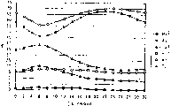
Fig. 3 represents the figure of the result of calculation of the thermal diffusion layer thickness of optical data recording medium of one embodiment of the invention and optical characteristics relation.
Fig. 4 represents the figure of the result of calculation of the thermal diffusion layer thickness of optical data recording medium of one embodiment of the invention and Ac/Aa relation.
Fig. 5 represents the figure of the result of calculation of the thermal diffusion layer thickness of another optical data recording medium of one embodiment of the invention and optical characteristics relation.
Fig. 6 represents the figure of the result of calculation of the thermal diffusion layer thickness of another optical data recording medium of one embodiment of the invention and Ac/Aa relation.
Fig. 7 represents the layer section of structure of the multilayer recording medium of one embodiment of the invention.
Fig. 8 represents the layer section of structure of the multilayer recording medium that two groups of media by one embodiment of the invention constitute.
Fig. 9 represents the sectional view of layer structure one example of phase-change recording medium in the past.
Embodiment
Below, be described more specifically the present invention with embodiment.
<the first embodiment 〉
Fig. 1 is the sectional view of layer structure of the optical data recording medium of expression first embodiment of the invention.
As shown in Figure 1, the optical data recording medium of present embodiment is by substrate 1, protective seam 2, contact bed 3, recording layer 4, contact bed 5, light-transmission type reflection horizon 6 and the thermal diffusion layer 7 of sequential aggradation constitutes on substrate 1.Wherein, recording layer 4 is by the material of the reversible variation of optical characteristics is constituted.
Having, the invention is not restricted to said structure, also can be the structure that is equipped with recording layer 4, light-transmission type reflection horizon 6 and the thermal diffusion layer 7 that is connected with light-transmission type reflection horizon 6.For example, can followingly constitute: in Fig. 1, other layers such as protective seam can be set between contact bed 5 and light-transmission type reflection horizon 6; Replace protective seam 2 with whole interface layer 3; Or contact bed 3 is not set; Or the like, in various structures, all can adopt the present invention.
As the material of substrate 1, can use resins such as polycarbonate, PMMA or glass etc.In addition, in substrate 1, can be formed for importing the guiding groove of laser.
The fundamental purpose that protective seam 2 is set is to regulate the effectively optical characteristics of light absorption of recording layer 4.As the material of protective seam 2, can use the ZnS sulfides, SiO
2, Ta
2O
5, Al
2O
3Deng oxide, Ge-N, Si
3N
4, Al
3N
4On nitride, oxides of nitrogen such as Ge-O-N, Si-O-N, Al-O-N, dielectrics such as carbonide, fluoride, or the appropriate combination (ZnS-SiO of these materials
2Deng) etc., and the material that can realize above-mentioned purpose.
Contact bed 3,5 is being born the effect of the protection recording layer 4 of the oxidation that prevents recording layer 4, burn into distortion etc., simultaneously, as described below, by be connected setting with recording layer 4, also has two important effects.
First vital role of contact bed is that the atom diffusion at recording layer 4 and protective seam 2 particularly contains under the situation of sulphur or sulfide in protective seam 2, have the effect of these compositions to recording layer 4 diffusions that prevent.By preventing this atom diffusion, the repeat property of medium is improved tremendously.The position that contact bed is set can be in a wherein side of recording layer 4, also can be in its both sides, but atom diffusion be preferably disposed on both sides in order more effectively to prevent.Only be provided with under the situation of contact bed on the interface of the wherein side of recording layer 4, by being arranged on the big side of thermal load, the side that raises on the temperature when promptly being arranged on record, deletion (in most cases being the laser light incident side) can improve the effect that suppresses atom diffusion.Have, the composition that contains in contact bed is diffused into the situation in the recording layer 4 in addition after the information duplicate record again, even but this situation is arranged, as the constituent material of contact bed, can use the material that is difficult for hindering recording layer 4 optical change.
Second vital role of contact bed is, is being connected with recording layer 4 under the situation about being provided with, and do not damage the thermal stability of record mark (amorphous fraction), plays the effect that promotes the recording materials crystallization.Because contact bed has such vital role, so can carry out deletion at a high speed faster.Especially the cooling that cooling the time is produced after contact bed being arranged on because of the laser radiation recording layer advances on the interface of side or the nuclei of crystallization form under the situation on the interface of side easily fast, promptly in most of the cases, be arranged under the situation on the recording layer interface of a side opposite with the laser light incident side, it is remarkable that this effect becomes.
More than, according to two effects of contact bed, for compatibility under at a high speed good rewriting characteristic and good these two aspects of repeat property, contact bed can be arranged on the both sides of recording layer 4.But, also have under the record condition of medium can the situation of pine, for example under the good situations such as repeat property of special requirement under the situation of low linear velocity, low density condition and not, the situation of contact bed is not set especially.
The material that constitutes contact bed 3,5 can be the material with above-mentioned effect, but also can be to be the material of principal ingredient with nitride, oxides of nitrogen, oxide, carbonide or fluoride.According to circumstances, also can mixed sulfides or selenide.For example, can use Ge-N, Cr-N, Si-N, Al-N, Nb-N, Mo-N, Ti-N, Zr-N, Ta-N etc. as nitride, Ge-O-N, Cr-O-N, Si-O-N, Al-O-N, Nb-O-N, Mo-O-N, Ti-O-N, Zr-O-N, Ta-O-N etc. can be used as oxides of nitrogen, SiO can be used as oxide
2, Al
2O
3, TiO
2, Ta
2O
5, Zr-O etc., can use Ge-C, Cr-C, Si-C, Al-C, Ti-C, Zr-C, Ta-C etc. as carbonide, can use LiF, CaF etc. as fluoride.Perhaps, also can use their suitable potpourri.In addition, under the situation of mixing an amount of sulfide and selenide, can use ZnS, ZnSe etc.In a word, material as contact bed 3,5, can use the material that is difficult for causing to recording layer 4 diffusions, even or also can not hinder the material of the optical change of recording layer 4 under the situation in diffusing into recording layer 4, and, be connected with recording layer 4 under the situation about being provided with, can using the material that promotes recording layer 4 crystallizations.
The thickness of contact bed 3,5 can be more than 1nm.Under the thickness of contact bed 3,5 was situation below the 1nm, the effect that prevents of atom diffusion can descend.
As the material of recording layer 4, can use the material of the reversible variation of optical characteristics.Under the situation of phase-change recording medium, can use the chalcogenide material as principal ingredient with Te, Se.For example, can list with Te-Sb-Ge, Te-Sb, Te-Sb-Zn, Te-Sb-Ag, Te-Bi-Ge, Te-Sb-Ge-Se, Te-Sn-Ge-Au, Te-Sb-Ag-In, Se-In-Sb, Te-Se-In is material of principal ingredient etc.
In recording layer 4, though can comprise sputter gas compositions such as Ar, Kr and H, C, H
2Impurity such as O, but its containing ratio preferably is suppressed to the degree of the record reproducing that does not hinder signal.In addition, for various purposes, though the situation of adding other material of trace (below about 10at%) in the principal ingredient of recording layer 4 is arranged, in this case, its amount preferably is suppressed to the degree of the record reproducing that does not hinder signal.
The thickness of recording layer 4 can be below the above 20nm of 3nm.Under the situation of the not enough 3nm of the thickness of recording layer 4, recording materials are difficult to reach uniform stratiform, between amorphous and crystallization, be difficult to produce effective phase change, and at the thickness of recording layer 4 under the situation more than the 20nm, because it is big that the thermal diffusion in the recording layer face becomes, when writing down, be easy to generate adjacent deletion by high density.
As the material in reflection horizon 6, can use to comprise material at least a among Au, Ag, the Cu.Use the reason of these materials to be that its optical constant helps increasing the Ac/Aa value, in addition, its reason also is, in order to increase heat-conduction coefficient, also can obtain big cooling power even thickness is thin.In addition, as the material in reflection horizon 6, also can use among Au, Ag, the Cu at least a, with other mixtures of material or alloy.Use the purpose of these other materials to be to prevent corrosion and to carry out more effective optical design.Specifically, can list Cr, Pt, Pd, Al, Mg, W, Ni, Mo, Si, Ge etc., but, also can use the material of suitable selection according to purposes.
The thickness in reflection horizon 6 can be below the above 20nm of 1nm.Under the situation of the not enough 1nm of the thickness in reflection horizon 6, be difficult to make film to reach uniform stratiform, reflection horizon effect heat, optics is descended, and under the thick situation of the Film Thickness Ratio 20nm in reflection horizon 6, because the light transmission of medium diminishes, so be difficult to realize above-mentioned light absorption compensation (Ac/Aa>1).
Below, the thermal diffusion layer 7 of the major part that constitutes feature of the present invention is described.Thermal diffusion layer 7 has two important effects.
First effect of thermal diffusion layer 7 is the heat that cooling produces in recording layer 4.As reflection horizon 6, under the thin layer situation of using light-transmission type, the cooling effect in reflection horizon 6 can descend.In order to compensate cooling effect, do not lose the optical characteristics of medium, promptly keep original medium transmitance, in thermal diffusion layer 7, carry out effective thermal diffusion.Therefore, the absorption in the record reproducing optical maser wavelength zone of thermal diffusion layer 7 must be low to moderate to a certain degree.When the complex refractive index of the record reproducing optical maser wavelength of thermal diffusion layer 7 was n-ik, absorption coefficient k preferably satisfied the relation of k≤1.5.In addition, for the cooling effect that makes thermal diffusion layer 7 is bigger, the heat-conduction coefficient that constitutes the material of thermal diffusion layer 7 is preferably tried one's best big.As standard, the material of the heat-conduction coefficient in the time of can using 500K more than 0.05W/mK.Utilize the cooling effect of this thermal diffusion layer 7, can improve the C/N ratio of tracer signal.In addition, owing to the thermal load that can reduce, so can also improve the duplicate record characteristic to medium.
Second effect of thermal diffusion layer 7 is, by regulating its thickness d, compares with the situation that thermal diffusion layer 7 is not set, and the Ac/Aa value when the dieletric reflection rate is identical is bigger.This is because the thickness d of thermal diffusion layer 7 can be in the interior situation of scope of 0<d≤(5/16) λ/n or (7/16) λ/n≤d≤(1/2) λ/n.At the thickness d of thermal diffusion layer 7 is under the situation of certain value in the described scope, and Ta, Tc (Ta is the medium transmitance of recording layer 4 when being in noncrystalline state, and Tc is the medium transmitance of recording layer 4 when being in crystalline state) can increase.Under 0 the situation of being absorbed as of the layer except that recording layer 4, reflection horizon 6, in theory, showing the situation that this Ac/Aa improves effect is the situation that thickness d satisfies 0<d≤(1/4) λ/n.But for example the absorption at contact bed is not that 0 situation is inferior, by the layer structure of medium, understands some and departs from this optimum range.The above-mentioned scope of the thickness d of thermal diffusion layer 7 considers to estimate that this deviation is about about (1/16) λ/n.In addition, absorption at the layer except that recording layer 4, reflection horizon 6 is not under 0 the situation, for example the absorption in contact bed 3,5 and thermal diffusion layer 7 is not under 0 the situation, has by the scope littler than above-mentioned scope (for example, 0<d<λ/4 etc.) to obtain the situation that Ac/Aa improves effect.But, improve effect with Ac/Aa and compare, under the situation of paying attention to above-mentioned cooling effect, even the optimum range of the thickness d of thermal diffusion layer 7 and optics has some departing from, the side that thickness d is big also can obtain good optical disk property.Therefore, if take all factors into consideration these situations, the optimum range of thickness d is thought above-mentioned scope.
More effective in order to make in second Ac/Aa raising effect that illustrates on of thermal diffusion layer 7, the refractive index n of thermal diffusion layer 7 preferably satisfies the relation of n>1.60.This is because the refractive index n of thermal diffusion layer 7 is big more, and the effect that increases Ta, Tc is just remarkable more.Wherein, the 1.60th, when not being set, the structure of thermal diffusion layer 7 is arranged on the roughly value of the refractive index of the layer (overlay and UV resin bed or dummy substrate etc.) on the side opposite that connects with reflection horizon 6 with the laser light incident side.
Requirement condition to thermal diffusion layer 7 with above-mentioned two vital role is summarized as follows.In expectation thickness d any one scope in 0<d≤(5/16) λ/n or (7/16) λ/n≤d≤(1/2) λ/n.In addition, be under the situation of n-ik at complex refractive index, preferably satisfy the relation of n>1.60, k≤1.5.Heat-conduction coefficient is preferably big as far as possible, is preferably in more than the 0.05W/mK when 500K.In addition, self-evident with the exception of this, thermal diffusion layer 7 should be the good film that does not crack, corrodes and peel off etc.
As the concrete material that satisfies these conditions, for example, can list Al-N, Al-O-N, Al-C, Si, Si-N, SiO
2, Si-O-N, Si-C, Ti-N, TiO
2, Ti-C, Ta-N, Ta
2O
5, Ta-O-N, Ta-C, Zn-O, ZnS, ZnSe, Zr-N, Zr-O-N, Zr-C, W-C.Perhaps, also can use their potpourri, also can use these materials and an amount of metal, semimetallic potpourri, also can use alloy.
Because optical data recording medium of the present invention has the light-transmission type structure, so can constitute by can carry out the multilayer recording medium that recording of information is reset from the laser radiation of single face.Thus, can realize the optical data recording medium of more high density recording.
Fig. 7 represents the structure example of the multilayer recording medium of present embodiment.As shown in Figure 7, the multilayer recording medium of present embodiment by substrate 23 and on substrate 23 group of the n by sequential aggradations such as separation layers 17,19,21 (n is the natural number that satisfies n 〉=2) medium 16,18 ..., 20,22 constitute.Wherein, count up to the medium 16,18 of (n-1) group from the laser light incident side ..., 20 (below, will be called ' n medium ' from the medium that the laser light incident side counts up to n group) are made of the light-transmission type medium.
Separation layers 17,19,21 etc. are made of resins such as ultraviolet curable resin and prolongation of effect resin or dielectric etc., are hyaline layer with respect to the laser that uses.In this case, only by from one-sided laser radiation, by the first~the (k-1) but medium record reproducing k medium (k is for satisfying the natural number of 1<k≤n).In fact, expectation is that two groups of media constitute multilayer recording mediums by n=2.
Can with from one of them of first medium to the n medium as playback tailored version medium (ROM (ROM (read-only memory))), but or also can be used as the only medium of write-once type.
Below, the multilayer recording medium that promptly is made of two groups of media with n=2 is that example is elaborated.
Fig. 8 represents the structure example of the multilayer recording medium that is made of two groups of media.As shown in Figure 8, this multilayer recording medium is by substrate 100, first medium 101, separation layer 109 and second medium 201 of sequential aggradation constitutes on substrate 100.First medium 101 is made of protective seam 102, contact bed 103, recording layer 104, contact bed 105, protective seam 106, reflection horizon 107 and the thermal diffusion layer 108 from substrate 100 side sequential aggradations.In addition, second medium 201 is made of protective seam 202, contact bed 203, recording layer 204, contact bed 205, protective seam 206 and reflection horizon 207 from separation layer 109 side sequential aggradations.In protective seam 102,106,202,206, contact bed 103,105,203,205, recording layer 104,204, reflection horizon 107,207, thermal diffusion layer 108, can use with medium shown in Figure 1 in the explanation identical materials.
Come design isolated layer 109 with isolation first medium 101 and second medium 201 as fundamental purpose,, constitute separation layer by the light absorption little material of trying one's best with respect to the laser that uses in the record reproducing.For example, can use the resin that constitutes by organic materials such as ultraviolet curable resin and late effect property resins, two sides adhesive sheet, the SiO that CD uses
2, Al
2O
3, inorganic dielectric such as ZnS or glass material etc.
Make a medium recording playback time, in order to suppress for a short time of insignificant degree from the cross (talk) of other medium, the thickness of separation layer 109 just must reach the above thickness of laser spot depth delta Z.Wherein, under 80% point the situation as benchmark of focal point intensity with no aberration situation, depth of focus Δ Z can represent by following formula approx.
ΔZ=λ/{2×(NA)
2}
Wherein, NA is the numerical aperture of object lens, and λ is the optical maser wavelength when carrying out record reproducing.For example, under the situation of λ=400nm, NA=0.60, the depth of focus becomes Δ Z=0.56 μ m.Therefore, in this case, in the scope that makes pact ± 0.60 μ m all in the depth of focus, the thickness of separation layer 109 must be set at least than 1.20 μ m big value.
In addition, but in order to make two distances between medium in the scope of object lens optically focused, but the thickness of expectation separation layer 109 is the thickness in the object lens allowable tolerance.
By making laser see through the record reproducing that first medium 101 carries out second medium 201.Therefore, be T1 in transmitance for optical maser wavelength first medium 101 that carries out record reproducing, reflectivity is R1, when only the reflectivity under second medium 201 was R2, the reflectivity r2 when resetting second medium 201 by first medium 101 can represent by following formula.
r2=R2×T1×T1
In addition, for signal amplitude, similarly, be Δ R2 in the reflection differences of second medium 201 itself, reset the reflection differences of second medium 201 under the situation of second medium 201 when being Δ r2 by first medium 101, following relation is set up.
Δr2=ΔR2×T1×T1
For example, at Δ R2=24%, during T1=50%, become by the reset reflection differences Δ r2 of second medium 201 under the situation of second medium 201 of first medium 101
Δr2=24%×0.5×0.5=6%。
As known from the above,, must improve the transmitance T1 of first medium 101 as far as possible, increase the signal amplitude of second medium 201 as far as possible in order from second medium 201, to obtain sufficient signal.Meanwhile, must improve the reflection differences of first medium 101 by certain degree, and, the recording sensitivity of second medium 201 must greatly be improved.The optical design of first medium 101, second medium 201 must be by these key element complete equipilibriums are determined.
Below, concrete optical design example is shown.As an example, reflectivity R1c during recording layer 104 crystalline states of first medium 101 is designed to 7.5%, reflectivity R1a during noncrystalline state is designed to 0.5%, reflectivity R2c during with recording layer 204 crystalline states of second medium 201 is designed to 15%, reflectivity R2a during noncrystalline state is designed to 43%, so that only the transmitance of first medium 101 under first medium, 101 enterprising line item situations reaches 50%.The adjusting of optical design value mainly is to be undertaken by the thickness that changes recording layer 104, protective seam 102,106, reflection horizon 107.
Under the situation of above example, be Δ r2=(43-15) * 0.5 * 0.5=7% by the reflection differences under first medium, 101 record reproducings, second medium, 201 situations, in addition, the reflection differences of first medium 101 also becomes 7.5-0.5=7%.Like this, expectation is the reflection differences of design first medium 101, second medium 201 like this, and promptly the size of signal amplitude about equally.According to such design, between first medium 101 and second medium 201, switch when carrying out the medium of record reproducing, by the extreme variation of signal amplitude, can prevent the instability that tracks.
In addition, owing to be difficult to make the high reflectance difference compatibility of high permeability and second medium of first medium, afterwards the most cases reflection differences is smaller so design, and it is smaller that signal amplitude can become.In this case, by more in the past than the power grade P3 that set playback light slightly bigly, can increase the replay signal amplitude.But if cross the grade of setting P3 greatly, so because record mark is subjected to the influence of heat, replay signal meeting deterioration is so must set the grade of P3 in the scope that does not produce the Signal Degrade that is produced by this playback light.In addition, first medium 101 can be distinguished different with the playback power grade of second medium 201.In addition, the optical maser wavelength of carrying out first medium 101 and 201 playbacks of second medium also can be different, but generally use the laser of same wavelength.
Expectation is reset the transmittance of first medium 101 under second medium, 201 situations more than 40% below 80%, and is preferably in more than 50% below 70%.As mentioned above, because the signal amplitude during by first medium, 101 record reproducings, second medium 201 becomes transmitance T1 square the value that multiply by first medium 101, so the transmittance of first medium 101 than 40% little situation under, become below 0.16 times, it is quite little to become.In addition, under the very little situation of the transmittance of first medium 101, greatly reduce owing to see through the light quantity of second medium 201, so the recording sensitivity of second medium 201 can descend.Therefore, the transmittance of first medium 101 should be preferably in more than 50% more than 40%.But, if the transmittance of first medium 101 is excessive, so owing to the reflection differences that is difficult to increase first medium 101, so the transmittance of first medium 101 should be preferably in below 70% below 80%.
Below, be example with the optical data recording medium of being furnished with Fig. 1 structure, the manufacture method of the optical data recording medium of above explanation is described.Method as making the multilayer film that constitutes above-mentioned optical data recording medium has methods such as sputtering method, vacuum metallizing, CVD.Wherein, be that example describes with the situation that adopts sputtering method.Fig. 2 is the synoptic diagram that is expressed as film device one example.
As shown in Figure 2, vacuum tank 9 connects the vacuum pump (not shown) by exhausr port 15, can make thus to keep high vacuum in the vacuum tank 9.In addition, on vacuum tank 9, be provided with gas supply port 14, can supply with rare gas, nitrogen, oxygen or their mixed gas of firm discharge from this gas supply port 14.In Fig. 2, the 10th, be configured in the substrate in the vacuum tank 9, this substrate 10 is installed on the drive unit 11 that can make substrate 10 rotations and revolution.The 12nd, with a plurality of sputtering targets of substrate 10 arranged opposite, these sputtering targets 12 are connected with negative electrode 13 respectively in the vacuum tank 9.Wherein, negative electrode 13 is connected with direct supply or high frequency electric source (not shown) by not shown switch.In addition, by with vacuum tank 9 ground connection, vacuum tank 9 and substrate 10 have anodize.
As film forming gas, can use rare gas or according to circumstances use the gas that in rare gas, is mixed with trace nitrogen or oxygen etc.As rare gas, can use film-formable gases such as Ar, Kr.In general, known when film forming recording layer 4 and protective seam 2, if the gas that uses the oxygen of the nitrogen of rare gas and trace or trace to mix, the material in the time of can suppressing the medium duplicate record so moves, the raising repeat property.
As contact bed 3,5 or thermal diffusion layer 7, under the situation of using nitride and oxide,, can obtain the good film of quality so if carry out sputter according to the reactive sputtering method.For example,, using under the situation of Ge-Cr-N, work as target with Ge-Cr or the material that comprises Ge, Cr and O, as the mixed gas of film forming gas use rare gas and nitrogen as contact bed 3,5.Perhaps, also can use and comprise N
2O, NO
2, NO, N
2Deng the gas of nitrogen-atoms and the mixed gas of these gases of appropriate combination and rare gas.In addition, be under the situation of hard at film and the big situation of membrane stress inferior, as required, be blended in the film forming gas by oxygen with trace, the situation that can obtain good film quality layer is arranged.
The following describes recording/reproducing method, the delet method of the optical data recording medium that forms as described above.In the record reproducing of signal, deletion, track control device and focus control device, the laser driving apparatus of modulated laser power and the rotating control assembly of rotating media of the position of the drive unit that uses the shaven head that loads LASER Light Source and object lens, the position of irradiating laser is imported to the precalculated position, control track direction and the direction vertical with face.
At first, use rotating control assembly to make the medium rotation, use optical system that laser is dwindled into small point, carry out record, the deletion of signal by shining to medium.Irradiation by laser, it is P1 that part in the recording layer 4 reversibly changes the noncrystalline state generation power grade that obtains to noncrystalline state, by identical laser radiation, the crystalline state generation power grade that obtains to the reversible variation of crystalline state is P2, utilize modulated laser power to make between P1 and P2, form record mark or deletion.Thus, carry out recording of information, delete and write record.The part of irradiation P1 power is formed by train of impulses, is generally so-called multiple-pulse.
In addition, by than the laser radiation under this low power grade of any one power grade among above-mentioned P1, the P2, the optical states of record mark is unaffected, and, make that to reset by this irradiation for record mark be P3 from the power grade that medium obtains abundant reflectivity, by read the signal that the laser radiation that utilizes P3 power obtains with detecting device, carry out the playback of information signal from medium.
[embodiment]
Below, the preferred embodiments of the present invention are described.
In the present embodiment, be the discoid polycarbonate resin of 0.6mm, diameter 120mm as substrate 1 used thickness, adopt the SiO that in ZnS, mixes 20mol% as protective seam 2
2Material, adopt Ge as recording layer 4
21Sb
25Te
54, adopt Ge-Cr-O-N as contact bed 3,5, adopt Au as reflection horizon 6, adopt Al-O-N as thermal diffusion layer 7, make the optical data recording medium of structure shown in Figure 1.
Fig. 3 represents the optical characteristics analog result of this moment.Wherein, the thickness of each layer is that recording layer 4 is 10nm, and contact bed 3,5 is respectively 20nm, 30nm, and reflection horizon 6 is 10nm.And; (λ is an optical maser wavelength to the thickness that makes protective seam 2 and thermal diffusion layer 7 from 0 to λ/2n; refractive index when n is the wavelength X of each film) changes; absorptivity Aa-RL, Ac-RL in absorptivity Aa, Ac in the crystalline state of the recording layer 4 when being respectively noncrystalline state, to(for) recording layer 4, reflectivity Ra, Rc and the reflection horizon 6, transmitance Ta, the Tc of medium carry out optical computing.Transverse axis is represented as the thickness of thermal diffusion layer 7 (unit: * λ/64n), the value when the Ac/Aa value reaches maximum in the structure that satisfies Ra≤5% and Rc 〉=15%.The thickness of the protective seam 2 of this moment is about (26~30) λ/64n.As a comparative example, transverse axis is 0 the place result of calculation when representing thermal diffusion layer 7 is not set in the drawings.In addition, Fig. 4 represents the variation of the Ac/Aa value that obtained by above-mentioned optical computing.By Fig. 3, Fig. 4 as can be known, satisfy under the situation of 0<d≤λ/4n at the thickness d of thermal diffusion layer 7 (Al-O-N), compare with the situation that thermal diffusion layer 7 (Al-O-N) is not set, the Ac/Aa value when roughly the same Rc, Ra increases.
Use above-mentioned material, make CD in fact as shown in Figure 1.The thickness of each layer is that protective seam 2 is 100nm, and recording layer 4 is 10nm, and contact bed 3,5 is respectively 10nm, 30nm, and reflection horizon 6 is 10nm, and thermal diffusion layer 7 is respectively 40nm (8 λ/64n), 60nm (12 λ/64n), 80nm (16 λ/64n).These media are respectively (1), (2), (3).
As a comparative example, in medium (1), except thermal diffusion layer 7 is not set, make the medium (0) that same structure is arranged with (1).
Wherein, supply with the gas that mixes 2.5% nitrogen in Ar that whole pressure can reach 1.0mTorr, 0.5mTorr respectively by certain flow, dropping into DC on negative electrode respectively is 1.27W/cm
2, RF is 5.10W/cm
2Power, carry out the film forming of recording layer 4 and protective seam 2.Can reach 3.0mTorr by whole pressure and supply with Ar gas, drop into DC4.45W/cm
2Power, carry out the film forming in reflection horizon 6.Film forming contact bed 3,5 o'clock, target material was Ge-Cr, and sputter gas is the mixed gas of Ar and nitrogen, and sputter gas pressure is 1mTorr, and the nitrogen partial pressure in the sputter gas is 40%, and sputtering power density is 6.37W/cm
2
Carry out the evaluating characteristics of CD by reflectivity, C/N ratio and rewriting deletion rate.
The aspect of record is (8-16) modulation system, uses the laser of wavelength 650nm and the object lens of numerical aperture 0.60 to carry out record.In addition, the shortest bit length is 0.2 μ m (promptly the shortest mark lengths is 0.41 μ m), and the rotational speed of CD is linear velocity 8.2m/s.In addition, as substrate 1, using track pitch is the substrate of 1.20 μ m, promptly uses to be staggered to form every the slot part of 0.60 μ m and the substrate of land part.
By the mark of record 3T length in (8-16) modulation system, measure this C/N ratio, carry out the evaluation of C/N ratio.In addition, by behind the mark of 3T length under record (8-16) modulation system under the suitable laser power, 11T tag delete rate (hereinafter referred to as ' 11T deletion rate ') when measuring the 3T tag delete rate (hereinafter referred to as ' 3T deletion rate ') when rewriteeing in the 11T length mark and rewriteeing the 3T mark on the 11T mark is deleted the evaluation of characteristic.The evaluation result of expression medium (0)~(3) in following (table 1).
[table 1]
| The medium sequence number | Reflectivity (%) | Transmitance (%) | C/N is than (db) | 3T deletion rate (db) | 11T deletion rate (db) | ||
| Rc | Ra | Tc | Ta | ||||
| (0) | 16.1 | 4.7 | 20.0 | 40.0 | 52.0 | 30 | 33 |
| (1) | 16.2 | 4.5 | 24.5 | 48.0 | 54.5 | 33 | 36 |
| (2) | 16.8 | 4.4 | 23.8 | 48.0 | 55.0 | 33 | 35 |
| (3) | 17.1 | 4.2 | 21.0 | 45.0 | 55.0 | 32 | 34 |
By above-mentioned (table 1) as can be known, compare, in the medium of thermal diffusion layer (1)~(3) are arranged, make wherein any one C/N than all being improved with the medium that does not have thermal diffusion layer (0).Can think that this is owing to realized the cooling effect of thermal diffusion layer 7 (Al-O-N).In addition, in medium (1)~(3), any one in 3T deletion rate, the 11T deletion rate all is improved.The Ac/Aa of this expression medium improves.Have, in above-mentioned (table 1), Ta is the transmitance of recording layer 4 when being in noncrystalline state again, and the transmitance that Tc is a recording layer 4 when being in crystalline state.Wherein, by make the CD that has with medium (0)~(3) identical structure on the minute surface substrate, the transmitance of using optical splitter to measure these CDs is carried out the transmitance of medium and is measured.By above-mentioned (table 1) as can be known, compare with the medium that does not have thermal diffusion layer (0), in the medium of thermal diffusion layer (1)~(3) were arranged, wherein any one transmitance all had raising.
Below, illustrate except contact bed 3,5 for Cr-Al-O-N, thermal diffusion layer 7 for the Si, with medium (1) medium of same structure is arranged.Fig. 5, Fig. 6 represent the analog result of optical characteristics.Each tunic of this moment is thick to be that recording layer 4 is 10nm, and contact bed 3,5 is respectively 20nm, 35nm, and reflection horizon 6 is 15nm.By Fig. 6, Fig. 7 as can be known, satisfy under the situation of 0<d≤12 λ/64n at the thickness d of thermal diffusion layer 7 (Si), compare with the situation that thermal diffusion layer 7 (Si) is not set, the Ac/Aa value when roughly the same Rc, Ra increases.
Then, in medium (1), except protective seam 2 is 120nm; contact bed 3,5 is respectively the Cr-Al-O-N of 20nm, 35nm; reflection horizon 6 is the Au of 15nm, and thermal diffusion layer 7 is that 30nm (beyond the Si of 8 λ/64n), makes the medium (4) that same structure is arranged with medium (1).
As the comparative example of this moment, except thermal diffusion layer 7 is not set, make the medium (0) that same structure is arranged with medium (4).In following (table 2), expression is carried out result with medium (0)~(3) identical evaluation with respect to medium (4), (0).
[table 2]
| The medium sequence number | Reflectivity (%) | C/N is than (db) | 3T deletion rate (db) | 11T deletion rate (db) | |
| Rc | Ra | ||||
| (0) | 15.1 | 1.2 | 52.4 | 30 | 32 |
| (4) | 16.5 | 1.4 | 54.3 | 33 | 35 |
By above-mentioned (table 2) as can be known, in this case, when thermal diffusion layer 7 is set, compare when thermal diffusion layer is not set, C/N than and the deletion rate improve.
(second embodiment)
Below, adopt other embodiment, further describe the present invention.Here, still with reference to the Fig. 8 that in above-mentioned first embodiment, uses.
In the present embodiment, be the discoid polycarbonate resin of 0.6mm, diameter 120mm as substrate 100 used thicknesses, as protective seam 102,106,202,206, adopt the SiO that in ZnS, mixes 20mol%
2Material, as contact bed 103,105,203,205, adopt Ge-Cr-N, as reflection horizon 107,207, adopt the AgPdCu alloy, as thermal diffusion layer 108, adopt TiO
2, and, adopt Ge as recording layer 104,204
4Sb
2Te
7, make the optical data recording medium of structure shown in Figure 8.The thickness of each layer is that recording layer 104,204 is respectively 6nm, 9nm; contact bed 103,105,203,205 is 2nm; reflection horizon 107,207 is respectively 10nm, 80nm; thermal diffusion layer 108 is 40nm; protective seam 102,106 is respectively 110nm, 34nm, and protective seam 202,206 is respectively 90nm, 40nm.
The membrance casting condition of each layer is identical with the situation of above-mentioned first embodiment.
By measuring the evaluating characteristics that carries out CD for first medium 101 and second medium, 201 both sides' C/N ratio, rewriting deletion rate and cycle characteristics.
The aspect of record is (8-16) modulation system, all uses the object lens of the laser of wavelength 405nm and numerical aperture 0.65 to write down in first medium 101, second medium 201 and resets.In addition, the shortest mark lengths is 0.26 μ m, and the rotational speed of CD is linear velocity 8.2m/s.In addition, as substrate 100, using track pitch is the substrate of 0.39 μ m, promptly uses the substrate that is staggered to form slot part and land part every 0.195 μ m.
In (8-16) modulation system,, measure the evaluation that this C/N recently carries out the C/N ratio by writing down 10 times under the laser power that being marked at of 3T length is suitable.In addition, after being marked at of the 3T length under (8-16) modulation system write down 9 times under the suitable laser power, mark with 11T length under equal-wattage rewrites 1 time, and the deletion rate (hereinafter referred to as ' 3T deletion rate ') of measuring the 3T mark of this moment rewrites the evaluation of deletion characteristic.Jitter value during in addition, by evaluation record random signal worsens on which record number of times is carried out the evaluation of cycle characteristics.
The power that carries out reproducing signals all is 1.0mW on first medium 101, second medium 201.The playback of second medium 201 is not being carried out under the state of tracer signal on first medium 101 easily.
Wherein, be medium (5) with above-mentioned dual-layer recording medium.For relatively, except that thermal diffusion layer 108 is not set, make the dual-layer recording medium that same structure is arranged with medium (5), this medium is medium (6).Under tabulate in 3 the result that expression is estimated medium (5) and medium (6).
[table 3]
| The medium sequence number | Thermal diffusion layer | C/N L1 L2 | Deletion rate L1 L2 | Cyclophysis L1 L2 |
| (5) | TiO 2 | ○ ○ | ○ ○ | ○ ○ |
| (6) | Do not have | × ○ | × ○ | × ○ |
In above-mentioned (table 3), first medium, 101 brief notes are L1, second medium, 201 brief notes are L2.In addition, compare, the situation more than the 50dB is represented with zero for C/N, and the situation usefulness * expression of not enough 50dB.In addition, for the deletion characteristic, resulting 3T deletion rate is that the above situation of 33dB is represented with zero, and the situation usefulness * expression of not enough 33dB.In addition, for cycle characteristics, with random signal duplicate record 10,000 times, the deterioration amount of the jitter value during with 10 duplicate records is represented with zero in the situation below 2% under suitable laser power, and the deterioration amount is than 2% big situation usefulness * expression.
By above-mentioned (table 3) as can be known, in the medium that thermal diffusion layer 108 is arranged (5), first medium 101 (L1), second medium 201 (L2) obtain big C/N ratio and high deletion rate simultaneously.Relative therewith, for first medium 101 (L1) of the medium that does not have thermal diffusion layer (6), all can only obtain than the low value of medium (5) in C/N ratio, deletion rate.
This is because in not having the medium of thermal diffusion layer (6), owing to be difficult to increase the light absorption offset (value of Ac/Aa) of above-mentioned crystalline state and noncrystalline state, so the deletion rate is low, and the C/N of the 3T signal behind 10 regenerative recordings is lower than also.
In the medium that thermal diffusion layer 108 is arranged (5), owing to not only obtain big C/N ratio and high deletion rate for first medium 101 (L1), and can realize high permeability simultaneously for first medium 101 (L1), so also can obtain superperformance for second medium 201 (L2).
In addition, if comparative medium (5) and medium (6), so obviously thermal diffusion layer 108 has the effect that cycle characteristics is improved.Can think that this is because by adopting thin reflection horizon, the cooling energy that thermal diffusion layer 108 compensation descend, in medium (5), in the time of can reducing duplicate record to the thermal load of medium.
In addition, as other example, with removing Ti-N, Ta
2O
5, the material beyond Si-N, the Zr-N is as the material of thermal diffusion layer 108, makes the dual-layer recording medium that same structure is arranged with medium (5) respectively, these media are medium (7)~(10).To medium (7)~when (10) carry out the evaluation identical with the front, can obtain and the same superperformance of medium (5).And, under the situation of these media (7)~(10), by thermal diffusion layer 108 is set, can also compatible high permeability and high absorption compensation, and also improve cycle characteristics significantly.
As described above, according to the present invention, is furnished with the recording layer that the laser radiation of utilizing reversibly changes optical characteristics, see through the reflection horizon of the described laser of wavelength X, with the thermal diffusion layer that is connected setting with described reflection horizon, when the refractive index of described thermal diffusion layer is n, be set in by thickness d in the scope of 0<d≤(5/16) λ/n or (7/16) λ/n≤d≤(1/2) λ/n described thermal diffusion layer, can further improve the cooling power of recording layer, simultaneously owing to raising by the Ac/Aa value, can reduce rewriteeing distortion, write down more high speed so can make, densification.In addition, utilize the cooling effect of thermal diffusion layer, the C/N that can make tracer signal is than improving.Have again, owing to the thermal load that can reduce, so can also improve the duplicate record characteristic medium.
Claims (13)
1. optical data recording medium, comprise the recording layer that utilizes laser radiation reversibly to change optical characteristics, see through the reflection horizon and the thermal diffusion layer that is connected setting with described reflection horizon of the described laser of wavelength X, it is characterized in that, when the refractive index of described thermal diffusion layer is n, the thickness d of described thermal diffusion layer is in the scope of 0<d≤(5/16) λ/n or (7/16) λ/n≤d≤(1/2) λ/n, and above-mentioned reflection horizon is between above-mentioned thermal diffusion layer and above-mentioned recording layer.
2. optical data recording medium as claimed in claim 1 is characterized in that, the heat-conduction coefficient when constituting the 500K of material of thermal diffusion layer is more than 0.5W/mK.
3. optical data recording medium as claimed in claim 1 is characterized in that, for the optical maser wavelength that is used for information recording and reproduction, the refractive index of thermal diffusion layer is more than 1.6.
4. optical data recording medium as claimed in claim 1 is characterized in that, for the optical maser wavelength that is used for information recording and reproduction, the absorption coefficient of thermal diffusion layer is below 1.5.
5. optical data recording medium as claimed in claim 1 is characterized in that thermal diffusion layer comprises from Al-N, Al-O-N, Al-C, Si, Si-N, SiO
2, Si-O-N, Si-C, Ti-N, TiO
2, Ti-C, Ta-N, Ta
2O
5, select in the group formed of Ta-O-N, Ta-C, Zn-O, ZnS, ZnSe, Zr-N, Zr-O-N, Zr-C and W-C at least a.
6. optical data recording medium as claimed in claim 1 is characterized in that, the reflection horizon comprises at least a material of selecting from the group of Au, Ag and Cu composition.
7. optical data recording medium as claimed in claim 1 is characterized in that, the thickness in reflection horizon is below the above 20nm of 1nm.
8. optical data recording medium as claimed in claim 1 is characterized in that, the thickness of recording layer is below the above 20nm of 3nm.
9. optical data recording medium as claimed in claim 1 is characterized in that, recording layer constitutes by comprise at least a phase-transition material of selecting from the group that Te, Se and Sb form.
10. optical data recording medium as claimed in claim 1 is characterized in that, with respect to the average transmittance of the optical data recording medium of laser more than 40% below 80%.
11. optical data recording medium as claimed in claim 10 is characterized in that, in a side opposite with the laser light incident side, is provided with at least one other optical data recording medium.
12. optical data recording medium as claimed in claim 1 is characterized in that, is provided with at least one side of recording layer to be connected, and has the contact bed that promotes recording layer crystallization effect.
13. optical data recording medium as claimed in claim 12 is characterized in that, contact bed is for comprising the material of N at least.
Applications Claiming Priority (2)
| Application Number | Priority Date | Filing Date | Title |
|---|---|---|---|
| JP33463798 | 1998-11-25 | ||
| JP334637/1998 | 1998-11-25 |
Publications (2)
| Publication Number | Publication Date |
|---|---|
| CN1254914A CN1254914A (en) | 2000-05-31 |
| CN1174399C true CN1174399C (en) | 2004-11-03 |
Family
ID=18279610
Family Applications (1)
| Application Number | Title | Priority Date | Filing Date |
|---|---|---|---|
| CNB991248953A Expired - Lifetime CN1174399C (en) | 1998-11-25 | 1999-11-25 | Optical information record medium |
Country Status (5)
| Country | Link |
|---|---|
| US (1) | US6449239B1 (en) |
| EP (1) | EP1005036B1 (en) |
| KR (1) | KR100372181B1 (en) |
| CN (1) | CN1174399C (en) |
| DE (1) | DE69929739T2 (en) |
Families Citing this family (30)
| Publication number | Priority date | Publication date | Assignee | Title |
|---|---|---|---|---|
| JP2001023245A (en) * | 1999-07-09 | 2001-01-26 | Sony Corp | Optical recording medium and optical recording device |
| US7009930B1 (en) | 1999-12-21 | 2006-03-07 | Matsushita Electric Industrial Co., Ltd. | Optical information recording medium, method of recording and reproducing, and optical recording and reproducing system |
| JP4269471B2 (en) * | 2000-02-21 | 2009-05-27 | ソニー株式会社 | Optical recording medium, optical pickup and optical recording / reproducing apparatus |
| KR100458299B1 (en) * | 2000-10-10 | 2004-11-26 | 티디케이가부시기가이샤 | Optical Recording Method and Optical Recording Medium |
| US6734455B2 (en) * | 2001-03-15 | 2004-05-11 | Micron Technology, Inc. | Agglomeration elimination for metal sputter deposition of chalcogenides |
| JP4814476B2 (en) * | 2001-04-20 | 2011-11-16 | Tdk株式会社 | Reproduction method of optical information medium |
| CN1244098C (en) * | 2001-09-12 | 2006-03-01 | 松下电器产业株式会社 | Optical information recording medium |
| JP4166455B2 (en) * | 2001-10-01 | 2008-10-15 | 株式会社半導体エネルギー研究所 | Polarizing film and light emitting device |
| JP4024510B2 (en) * | 2001-10-10 | 2007-12-19 | 株式会社半導体エネルギー研究所 | Recording medium and substrate |
| US20030190551A1 (en) * | 2002-04-05 | 2003-10-09 | Tdk Corporation | Optical recording medium and method for optically recording information in the same |
| US7479363B2 (en) | 2002-04-26 | 2009-01-20 | Tdk Corporation | Optical recording medium and method for optically recording data in the same |
| JP2004030843A (en) * | 2002-06-28 | 2004-01-29 | Pioneer Electronic Corp | Information recording and reproducing medium |
| US20040038080A1 (en) * | 2002-07-01 | 2004-02-26 | Tdk Corporation | Optical recording medium and method for recording data in the same |
| JP4092147B2 (en) * | 2002-07-04 | 2008-05-28 | Tdk株式会社 | Optical recording medium and optical recording method |
| JP4282285B2 (en) * | 2002-08-12 | 2009-06-17 | Tdk株式会社 | Optical recording medium and optical recording method |
| US20040076907A1 (en) * | 2002-10-22 | 2004-04-22 | Tdk Corporation | Optical recording medium and method for manufacturing the same |
| US7781146B2 (en) * | 2002-11-22 | 2010-08-24 | Tdk Corporation | Optical recording medium |
| AU2003289318A1 (en) * | 2002-12-13 | 2004-07-09 | Matsushita Electric Industrial Co., Ltd. | Optical information recording medium and method for manufacturing same |
| US7932015B2 (en) | 2003-01-08 | 2011-04-26 | Tdk Corporation | Optical recording medium |
| JP2005071402A (en) * | 2003-08-25 | 2005-03-17 | Tdk Corp | Optical information recording medium |
| JP2005122872A (en) * | 2003-09-22 | 2005-05-12 | Ricoh Co Ltd | Two-layer phase-change type information recording medium and its recording and reproducing method |
| US7858290B2 (en) * | 2003-10-02 | 2010-12-28 | Panasonic Corporation | Information recording medium and method for manufacturing the same |
| JP4064905B2 (en) * | 2003-10-29 | 2008-03-19 | 株式会社東芝 | Phase change optical recording medium |
| JP2005251279A (en) * | 2004-03-03 | 2005-09-15 | Nec Corp | Optical information recording medium and its manufacturing method |
| CN1934636A (en) * | 2004-03-18 | 2007-03-21 | 株式会社理光 | Phase transition type optical information recording medium and two layered phase transition type optical information recording medium |
| TW200601322A (en) * | 2004-04-07 | 2006-01-01 | Hitachi Maxell | Information recording medium |
| JP4227091B2 (en) * | 2004-10-01 | 2009-02-18 | 株式会社東芝 | Phase change optical recording medium |
| US20060114791A1 (en) * | 2004-11-30 | 2006-06-01 | Charles Marshall | Ultra-high data density optical media system |
| JP4193147B2 (en) * | 2005-09-29 | 2008-12-10 | 日本電気株式会社 | Optical information recording medium and manufacturing method thereof |
| US20070154674A1 (en) * | 2005-12-29 | 2007-07-05 | Imation Corp. | Recordable optical media with thermal buffer layer |
Family Cites Families (14)
| Publication number | Priority date | Publication date | Assignee | Title |
|---|---|---|---|---|
| EP0368194B1 (en) * | 1988-11-07 | 1998-06-17 | Hitachi, Ltd. | Magneto-optical recording medium |
| JP3038853B2 (en) * | 1990-09-13 | 2000-05-08 | 株式会社ニコン | Overwritable magneto-optical recording medium with high-level margin expanded |
| EP0566107B1 (en) | 1992-04-17 | 1998-03-18 | Matsushita Electric Industrial Co., Ltd. | Optical information recording medium and method of designing its structure |
| ES2131079T3 (en) | 1992-05-15 | 1999-07-16 | Ricoh Kk | REGISTRATION MEDIA OF OPTICAL INFORMATION AND REGISTRATION METHOD USING SUCH REGISTRATION MEDIA. |
| CN1083615A (en) * | 1992-08-19 | 1994-03-09 | 菲利浦电子有限公司 | Information storage system |
| JP3313246B2 (en) | 1994-08-08 | 2002-08-12 | 松下電器産業株式会社 | Optical information recording medium |
| JP3516996B2 (en) * | 1994-09-21 | 2004-04-05 | 株式会社東芝 | Information recording medium and method of manufacturing the same |
| JPH08129777A (en) | 1994-11-02 | 1996-05-21 | Matsushita Electric Ind Co Ltd | Optical information recording medium |
| JP2785763B2 (en) | 1995-09-27 | 1998-08-13 | 日本電気株式会社 | Phase change optical disk |
| TW336317B (en) | 1996-02-28 | 1998-07-11 | Asahi Chemical Ind | Design method of phase change type recording medium and the phase change optical recording medium |
| JPH09270156A (en) * | 1996-04-01 | 1997-10-14 | Canon Inc | Magneto-optical recording medium |
| TW414892B (en) | 1996-05-28 | 2000-12-11 | Ibm | Optical data storage system with multiple rewriteable phase-change recording layers |
| JP3738523B2 (en) * | 1997-04-09 | 2006-01-25 | 株式会社ニコン | Recordable optical disc |
| US6017620A (en) * | 1997-04-10 | 2000-01-25 | Tdk Corporation | Magneto-optical recording medium |
-
1999
- 1999-11-18 US US09/442,900 patent/US6449239B1/en not_active Expired - Lifetime
- 1999-11-23 EP EP99123167A patent/EP1005036B1/en not_active Expired - Lifetime
- 1999-11-23 DE DE69929739T patent/DE69929739T2/en not_active Expired - Lifetime
- 1999-11-25 KR KR10-1999-0052715A patent/KR100372181B1/en not_active IP Right Cessation
- 1999-11-25 CN CNB991248953A patent/CN1174399C/en not_active Expired - Lifetime
Also Published As
| Publication number | Publication date |
|---|---|
| DE69929739T2 (en) | 2006-08-10 |
| EP1005036A1 (en) | 2000-05-31 |
| DE69929739D1 (en) | 2006-04-20 |
| EP1005036B1 (en) | 2006-02-08 |
| KR100372181B1 (en) | 2003-02-14 |
| US6449239B1 (en) | 2002-09-10 |
| KR20000035689A (en) | 2000-06-26 |
| CN1254914A (en) | 2000-05-31 |
Similar Documents
| Publication | Publication Date | Title |
|---|---|---|
| CN1174399C (en) | Optical information record medium | |
| CN1150522C (en) | Optical information recording media and its recording regenerating method | |
| JP2001209974A (en) | Information recording medium | |
| CN1355526A (en) | Optical recording medium | |
| JP2000322770A (en) | Optical information recording medium | |
| JP4225996B2 (en) | Optical recording medium, information reproducing method, and optical information reproducing apparatus | |
| TW200414166A (en) | Optical information recording medium and process for recording thereon | |
| EP1667137A1 (en) | Two-layer phase-change information recording medium and its recording/reproducing method | |
| JP2000222777A (en) | Optical information recording medium | |
| TW200406006A (en) | Information recording medium | |
| JP2004178673A (en) | Phase change optical recording medium | |
| JP4248327B2 (en) | Phase change optical information recording medium | |
| JP2004005920A (en) | Phase-transition type information recording medium | |
| KR20050026477A (en) | Multi-stack optical data storage medium and use of such medium | |
| JP2004342283A (en) | Multilayer structured optical recording medium | |
| JP2008090984A (en) | Multilayer type phase transition optical recording medium | |
| JP3620597B1 (en) | Optical information recording medium | |
| JP2004318917A (en) | Optical recording medium | |
| JP2002269825A (en) | Optical recording medium | |
| JP2007164896A (en) | Optical information recording medium | |
| JP2004127477A (en) | Multilayered configuration type optical recording medium | |
| JP2005209247A (en) | Optical recording medium | |
| JP2004079151A (en) | Phase change information recording medium | |
| JP2007237437A (en) | Optical recording medium | |
| JP2007157202A (en) | Optical recording medium and initialization method therefor |
Legal Events
| Date | Code | Title | Description |
|---|---|---|---|
| C06 | Publication | ||
| PB01 | Publication | ||
| C10 | Entry into substantive examination | ||
| SE01 | Entry into force of request for substantive examination | ||
| C14 | Grant of patent or utility model | ||
| GR01 | Patent grant | ||
| CX01 | Expiry of patent term |
Granted publication date: 20041103 |
|
| CX01 | Expiry of patent term |