CN1174284C - Light source device and projector - Google Patents
Light source device and projector Download PDFInfo
- Publication number
- CN1174284C CN1174284C CNB01141040XA CN01141040A CN1174284C CN 1174284 C CN1174284 C CN 1174284C CN B01141040X A CNB01141040X A CN B01141040XA CN 01141040 A CN01141040 A CN 01141040A CN 1174284 C CN1174284 C CN 1174284C
- Authority
- CN
- China
- Prior art keywords
- box body
- projector
- flowing path
- light
- supply apparatus
- Prior art date
- Legal status (The legal status is an assumption and is not a legal conclusion. Google has not performed a legal analysis and makes no representation as to the accuracy of the status listed.)
- Expired - Fee Related
Links
Images


Classifications
-
- G—PHYSICS
- G03—PHOTOGRAPHY; CINEMATOGRAPHY; ANALOGOUS TECHNIQUES USING WAVES OTHER THAN OPTICAL WAVES; ELECTROGRAPHY; HOLOGRAPHY
- G03B—APPARATUS OR ARRANGEMENTS FOR TAKING PHOTOGRAPHS OR FOR PROJECTING OR VIEWING THEM; APPARATUS OR ARRANGEMENTS EMPLOYING ANALOGOUS TECHNIQUES USING WAVES OTHER THAN OPTICAL WAVES; ACCESSORIES THEREFOR
- G03B21/00—Projectors or projection-type viewers; Accessories therefor
- G03B21/14—Details
- G03B21/20—Lamp housings
-
- G—PHYSICS
- G03—PHOTOGRAPHY; CINEMATOGRAPHY; ANALOGOUS TECHNIQUES USING WAVES OTHER THAN OPTICAL WAVES; ELECTROGRAPHY; HOLOGRAPHY
- G03B—APPARATUS OR ARRANGEMENTS FOR TAKING PHOTOGRAPHS OR FOR PROJECTING OR VIEWING THEM; APPARATUS OR ARRANGEMENTS EMPLOYING ANALOGOUS TECHNIQUES USING WAVES OTHER THAN OPTICAL WAVES; ACCESSORIES THEREFOR
- G03B21/00—Projectors or projection-type viewers; Accessories therefor
- G03B21/14—Details
- G03B21/16—Cooling; Preventing overheating
-
- G—PHYSICS
- G03—PHOTOGRAPHY; CINEMATOGRAPHY; ANALOGOUS TECHNIQUES USING WAVES OTHER THAN OPTICAL WAVES; ELECTROGRAPHY; HOLOGRAPHY
- G03B—APPARATUS OR ARRANGEMENTS FOR TAKING PHOTOGRAPHS OR FOR PROJECTING OR VIEWING THEM; APPARATUS OR ARRANGEMENTS EMPLOYING ANALOGOUS TECHNIQUES USING WAVES OTHER THAN OPTICAL WAVES; ACCESSORIES THEREFOR
- G03B21/00—Projectors or projection-type viewers; Accessories therefor
- G03B21/14—Details
- G03B21/145—Housing details, e.g. position adjustments thereof
-
- G—PHYSICS
- G03—PHOTOGRAPHY; CINEMATOGRAPHY; ANALOGOUS TECHNIQUES USING WAVES OTHER THAN OPTICAL WAVES; ELECTROGRAPHY; HOLOGRAPHY
- G03B—APPARATUS OR ARRANGEMENTS FOR TAKING PHOTOGRAPHS OR FOR PROJECTING OR VIEWING THEM; APPARATUS OR ARRANGEMENTS EMPLOYING ANALOGOUS TECHNIQUES USING WAVES OTHER THAN OPTICAL WAVES; ACCESSORIES THEREFOR
- G03B21/00—Projectors or projection-type viewers; Accessories therefor
- G03B21/14—Details
- G03B21/20—Lamp housings
- G03B21/2086—Security or safety means in lamp houses
Landscapes
- Physics & Mathematics (AREA)
- General Physics & Mathematics (AREA)
- Engineering & Computer Science (AREA)
- Computer Security & Cryptography (AREA)
- Projection Apparatus (AREA)
- Arrangement Of Elements, Cooling, Sealing, Or The Like Of Lighting Devices (AREA)
- Non-Portable Lighting Devices Or Systems Thereof (AREA)
Abstract
A pair of openings (302) symmetrically disposed around an optical axis of the reflector (412) is formed on a contact surface of a light-transmissive plate (301) and the reflector (412) and a cooling channel (340) for introducing cooling air to a source lamp (411) through the pair of openings (302) and a first and a second cooling channel shutters (350, 360) for shutting the cooling channel (340) when the case is detached from a projector (1) are provided on a case (300). The source lamp (411) can be efficiently cooled, so that the life of the source lamp (411) can be lengthened. Even when a light-emitting tube of the source lamp (411) is exploded while using the projector (1), the fragments of the light-emitting tube do not fall outside in exchanging the light source (413), and cooling efficiency ofthe source lamp (411) is not impaired.
Description
Technical field
The present invention relates to a kind of be used for light beam that illuminator is penetrated according to the picture information modulation with form optical image, and with the projector of this optical image enlarging projection, this light supply apparatus has illuminator, the reverberator that the light optically focused of this illuminator emission is penetrated and the box body of taking in aforementioned illuminator and aforementioned reverberator.
Background technology
A kind of projector of Shi Yonging in the past was a light beam that illuminator is penetrated according to the picture information modulation forming optical image, and with the projector of this optical image enlarging projection.
Such projector is used on the information combination medium such as meeting, association, exhibition widely.For this reason, because of the image of projector projection is distinct, promote the high brightness of illuminator.
At this, as illuminator, use high-pressure mercury-vapor lamp or metal halide lamp, last from the life-span, the luminotron of being made by quartz glass can break, fragment can disperse.For this reason, the light supply apparatus that comprises this illuminator will adopt transparency glass plate etc. to cover the light outgoing plane of reverberator, thereby even illuminator breaks, the measure that fragment also can not disperse.
But in above-mentioned light supply apparatus, illuminator is because of being enclosed within the interior volume that is made of reverberator and transparency glass plate, and the temperature of illuminator easily raises, thereby, there is the problem of the illuminator lost of life.
Although consider on the part of reverberator and transparency glass plate, to form the opening that cooling air imports usefulness, with the structure of cooling luminotron, as form peristome, when illuminator breaks, be difficult to become not exclusively withered and fallen structure of fragment.
Summary of the invention
The purpose of this invention is to provide that even a kind of just in case illuminator breaks, fragment can be not withered and fallen yet to the outside and light supply apparatus and the projector grown of the life-span of cooling effectiveness height, illuminator.
For achieving the above object, light supply apparatus of the present invention be used for light beam that illuminator is penetrated according to the picture information modulation with form optical image, and with the projector of this optical image enlarging projection, and reverberator that the light optically focused of have illuminator, this illuminator being launched penetrates and the box body of taking in aforementioned illuminator and aforementioned reverberator, it is characterized in that, the light outgoing plane of described reverberator is covered by transparent panel, and formation is the pair of openings portion of center, symmetric arrangement with the optical axis of described reverberator on the surface of contact of this transparent panel and described reverberator; Described box body has the cooling flowing path that cooling air is imported described illuminator by described pair of openings portion, with when taking off, clog this cooling flowing path from described projector, and when installing on the described projector, open the cooling flowing path switching portion of this cooling flowing path.
At this, above-mentioned pair of openings portion also can downcut the part of transparent panel and form, but preferably, and a part that penetrates the front-end edge of direction by the light with reverberator is downcut the recess that forms and constituted.Can be on the direction that the optical axis of reverberator is kept straight on, cooling air is flowed near the illuminator as pyrotoxin, effectively cools light source lamp.At this moment, when pair of openings portion takes off from projector, preferably horizontal direction configuration.
In addition, the box body of taking in illuminator and reverberator is, has the box body to the locating surface of illuminator and reverberator location on the optical axis direction of the light beam that penetrates and the direction perpendicular to this optical axis, for example can be used as the formed products that is generated by injection moulding etc.
Adopt such the present invention, cooling air is imported the cooling flowing path of illuminator because of on box body, being formed with by pair of openings portion, thus cools light source lamp effectively, the serviceable life of improving illuminator.
In addition, owing to have the cooling flowing path switching portion that when taking off from projector cooling flowing path is clogged, even so the luminotron of illuminator breaks in the use of projector, when light supply apparatus is changed, the fragmentation of luminotron can be not withered and fallen to outside yet, when the installation of projector,, also can can't harm the cooling effectiveness of illuminator because this cooling flowing path switching portion has the formation of open cooling flowing path.In addition, when taking off from projector, be installed on the light supply apparatus for the mode of arranging, then when changing this light supply apparatus, can prevent reliably further that the fragmentation of luminotron is withered and fallen to outside phenomenon with horizontal direction as pair of openings portion.
In said structure, as above-mentioned cooling flowing path switching portion, can be freely to rotate axle on box body, have cover that the opening that will form on this box body clogs and to the force-applying piece of this cover towards the gyratory directions application of force; Perhaps, can be bearing on the box body with being free to slide, have cover that the opening that will form on this box body clogs and the force-applying piece of this cover towards the glide direction application of force; As cooling flowing path switching portion also can be the air that is formed at the cooling flowing path on the box body import with opening, air discharge with opening any, perhaps both and use.
Like this, portion is made of cover and force-applying piece by the cooling flowing path switching, just cooling flowing path switching portion can be arranged on the box body with simple structure, can simplify the manufacturing of light supply apparatus.
In addition, be preferably formed as on the above-mentioned box body and air imported cooling flowing path and/or from cooling flowing path, import conduit outside the box body outside box body.
By form conduit like this on box body, the importing of the cooling air outside box body, the discharge of cooled air outside box body can be carried out in the position corresponding to the cooling flowing path in the projector, can further improve the cooling effectiveness of light supply apparatus.
In addition, preferably be provided with the dustproof filtrator of using in the above-mentioned pair of openings portion.
At this, dustproof can only be arranged on the peristome that air in the pair of openings portion imports usefulness or air is discharged on the peristome of usefulness with filtrator, or all settings on two peristomes.
Like this, by the filtrator of dustproof usefulness is set, even, can prevent reliably that also fragmentation is withered and fallen outside box body just in case the luminotron of illuminator breaks.In addition, membrane filter is set, can prevents that dust from invading along with the importing of cooling air in the light supply apparatus, can prevent the phenomenon that the pollution because of luminotron causes brightness to reduce as the peristome that imports usefulness at air.
And projector of the present invention is characterised in that any one with above-mentioned light supply apparatus, adopts such projector, then can obtain and aforementioned same effect and effect.
In above-mentioned projector, have when light supply apparatus is installed, front end inserts cooling flowing path switching portion and cooling air is imported the conduit of this light supply apparatus.
By adopting conduit like this, can be reliably in the lead-in light source apparatus with the cooling air in the projector, the life-span of further having improved the cooling effectiveness of light supply apparatus and further having improved light supply apparatus.
In addition, be provided with the fan of cooling air being sent into its cardinal extremity one side on above-mentioned conduit, perhaps preferably, have in projector the air of cooling device inside when the outside exhaust manifolds of discharging of device, cardinal extremity one side of above-mentioned conduit is connected with exhaust manifolds.
Like this, by fan is set on conduit, and be connected, cooling air can be sent into cooling flowing path forcibly by conduit, promoted the circulation of cooling air, further improved the cooling effectiveness of light supply apparatus with exhaust manifolds.
Description of drawings
Fig. 1 is for watching the overall perspective of the projector of one embodiment of the invention from the top.
Fig. 2 is for watching the overall perspective of projector the previous embodiment from the below.
Fig. 3 is for watching the overall perspective of projector the previous embodiment from the below.
Fig. 4 is the overall perspective that projector inside in the previous embodiment is shown.
Fig. 5 is for schematically illustrating the vertical view of each optical system of projector in the previous embodiment.
Fig. 6 is the skeleton view that the light bulking block of projector in the previous embodiment is shown.
Fig. 7 is the skeleton view that light supply apparatus in the previous embodiment is shown.
Fig. 8 is the decomposition diagram that light supply apparatus in the previous embodiment is shown.
Fig. 9 is the skeleton view that light supply apparatus in the previous embodiment is shown.
Figure 10 is the view that Bright Source Protection portion in the previous embodiment is shown.
Figure 11 is the synoptic diagram that the 1st cooling flowing path switching portion switch in the previous embodiment is shown.
Figure 12 is the synoptic diagram that the 2nd cooling flowing path switching portion switch in the previous embodiment is shown.
Figure 13 is the skeleton view that the cooling construction of light supply apparatus in the previous embodiment is shown.
Figure 14 is a variation of the present invention, and the skeleton view of the cooling construction of light supply apparatus is shown.
Embodiment
Below, embodiments of the invention are described with reference to the accompanying drawings.
1. the main composition of projector
Fig. 1 is for watching the overall perspective of the projector 1 of present embodiment from the top, Fig. 2, Fig. 3 are for watching the overall perspective of projector 1 from the below, and Fig. 4 is the skeleton view that projector 1 inside is shown.
The form of projector 1 is, from the beam separation Cheng Hong (R) that penetrates as the light supply apparatus of light source, green (G), blue (B) three primary colors, these each color beams are by constituting liquid crystal board electro-optical device, that become optic modulating device, modulated corresponding with picture information, modulated beam of light of all kinds after the modulation is synthetic by intersection color separation prism 45, represent on the projecting plane, to amplify by projection lens 46.Each member is accommodated in the inside of outer dress box 2, but projection lens 46 is arranged under its zoom mechanism effect, as required can be outstanding from outer dress box 2.
In Fig. 1~Fig. 4, projector 1 has the outer dress box 2 that becomes box body, is contained in the supply unit 3 in the outer dress box 2, and the plane in the dress box 2 is the optical devices 4 of L font outside being disposed at equally, all roughly is rectangular shape.
Outer dress box 2 is basically by the upper cartridge body 21 of the sheet metal system of cladding system upper surface, the lower box body 23 that the magnesium of constituent apparatus basal surface etc. is molded into, be plugged between upper cartridge body 21 and the lower box body 23, bending machining such as aluminium or iron plate become, constitute with the middle box body 22 of cladding system side surface.These box bodys 21,22,23 pass through screw retention mutually.
Upper cartridge body 21 is formed by upper surface part 211 and side surface part 212 of being arranged on around it, and employing is as the metal pattern press forming.In addition, in the anterior 211A of side surface part 212 side, be provided with and install the erecting frame 24 corresponding circular hole opening 211D of projection lens 46, the periphery of circular hole opening 211D is processed to an inner lateral bending song by undergauge.In addition, form notch part 211C (with reference to Fig. 3) on the side vertical of side surface part 212 with anterior 211A.
The operating switch 2B that adjusts the image quality of projector 1 is arranged on projection lens 46 1 sides of the upper surface part 211 of upper cartridge body 21.A plurality of hole 2C that the speaker uses penetrate in the both sides of this operating switch 2B.
Middle box body 22 is as described above by forming bending machining such as aluminium sheet, formed box body includes the 1st box body component 22A and the 2nd box body component 22B that projection lens 46 configurations in left and right sides clamping, and the 3rd box body component 22C that is positioned at the 1st box body component 22A back side, between the 1st box body component 22A and the 3rd box body component 22C, configuration is connecting interface board and is exposing parts 22D, the various connectors of using with the interface on the interface board 92 that exposes internal configurations, and between the 2nd box body component 22B and the 3rd box body component 22C, be provided with lampshade 22E to be opened/closed.
Each box body component 22A, 22B, the 22C aluminium sheet by the regulation shape that will be become by stamping-outs such as press or Mechanical Processing Centers etc. are bending machining suitably, becomes the shape of aforementioned upper cartridge body 21 and lower box body 23 combinations.
Be formed between the front end 221A of the 1st box body component 22A front one side and the 2nd box body component 22B and form and aforementioned lens mounting frame 24 corresponding opening (not shown)s.In addition, form not shown peristome in the front end 221A of the 2nd box body component 22B one side, this peristome is opposite to the exhausr port 24A on the lens mounting frame 24.
And this lens mounting frame 24 is by on the box body 22 in being installed to, and constituting should middle box body 22.In addition, around exhausr port 24A, adhere to for example plastic cover piece 240.
On the 2nd box body component 22B, be provided with the handle opening 221B that extends and be spaced from each other given size from lower box body 23 1 side direction upper cartridge bodies 21 1 sides with given size, these openings 221B place be installed with move projector 1 when the handle 80 of use.
Lampshade 22E for example, has the knob parts 81 that are fastened to the 2nd box body component 22B one side with screw etc., and engages with the ora terminalis of the 3rd box body component 22C as shown in Figure 3.These knob parts 81 screw by E ring and not shown nut on being formed at the 2nd box body component 22B and cooperate.Rotary knob parts 81 when releasing cooperates with screwing of nut, only depend on spiral to cooperate, and knob parts 81 just can eject from lampshade 22E.Then, catch these knob parts 81, during along the side slip lampshade 22E of projector 1, can take off this lampshade 22E.In addition, knob parts 81 can not take off from lampshade 22E owing to by the E ring bearing, cooperate with the spiral of nut even remove yet.
In this lower box body 23, two corner portions located in bottom surface sections 231 the place aheads be provided with adjust all gradients of projector 1 with the corresponding to height and position adjusting mechanism 7 in the position of projection image.Relative with it, at central chimeric the resinous support foot part 6 (Fig. 3) of the rear of bottom surface sections 232 side.In addition, constituting of height and position adjusting mechanism 7 when rotating the rotating disk part, by the operation rod member, can be advanced and retreat at projected direction, by adjusting its advance and retreat amount, the height of variable demonstration drawing or gradient.
In addition, on the bottom surface sections 231 of lower box body 23, fan guard 235 is housed.In addition, also be provided with and lens mounting frame 24 corresponding circular hole opening 232D at the anterior 232A of lower box body 23.
Be provided with the suction hole 2A that imports cooling air to inside on the dress box body 2 outside this, with the exhausr port 24A that cooling back air is discharged, operating switch 2B is with the corresponding a plurality of hole 2C in speaker's position, the opening 221B that handle is used etc.In addition, as shown in Figure 2, also can form the suction hole 221F that cooling air is imported inside with opening 221B place at handle.
Lamp drive circuit 101 is supplied with electric power the illuminator 411 (Fig. 5) of the light source that becomes optical devices 4.In addition, the device front of this lamp drive circuit 101 side be provided with air import projector described later 1 inside, as the axial flow drawing fan 70 of cooling fan.
2. the detailed formation of optical system
In Fig. 5, integration lamp optical system 41 is for the image of 3 pieces of liquid crystal boards 441 (each of each coloured light of red, green, blue represented by liquid crystal board 441R, 441G, 441B respectively) that will constitute electro-optical device 44 forms the optical system of roughly evenly throwing light in the zone, has light supply apparatus 413, UV filter 418, as the 1st lens arra the 414, the 2nd lens arra 416, polarized light conversion element 415, overlapping lens 419 and the catoptron 424 of beam cutting element.
The light supply apparatus 413 that constitutes integration lamp optical system 41 has the reverberator 412 that is reflected as the illuminator 411 of the radiation light source that penetrates radial light and radiating light that illuminator 411 is penetrated.As illuminator 411, use halogen lamp or metal halide lamp, perhaps high-pressure mercury-vapor lamp more.Adopt paraboloidal mirror as reverberator 412, but also can use the lens (concavees lens) of off-axis paraboloids and ellipsoids mirrors and parallelization.
Constituting of the 1st lens arra 414 is arranged in rectangular from the optical axis direction lenslet 414A with essentially rectangular profile that looks.Each lenslet 414A penetrates illuminator 411 and the light beam by UV filter 418 is divided into the multi beam segment beam.The contour shape of each lenslet 414A is set roughly similar shapes of shape that image with liquid crystal board 441 forms the zone for.For example, the image of liquid crystal board 441 forms the aspect ratio (horizontal and linear foot cun ratio) in zone as being 4: 3, then the aspect ratio of each lenslet 414A also can be set at 4: 3.
The 2nd lens arra 416 has the formation roughly the same with the 1st lens arra 414, has lenslet 416A and is arranged in rectangular formation.The 2nd lens arra 416 have with overlapping lens 419 together, with the function of picture imaging on liquid crystal board 441 of each lenslet 414A of the 1st lens arra 414.
Be specially, the each several part light that converts a kind of polarized light to by polarized light conversion element 415 is by overlapping lens 419, roughly is overlapped on liquid crystal board 441R, 441G, the 441B of electro-optical device 44.In the projector 1 (electro-optical device 44) of the liquid crystal board 441 of the use modulated polarized light type of present embodiment owing to can only utilize a kind of polarized light, send other kinds random polarization illuminator 411 light almost half can not utilize.
At this, by using polarized light conversion element 415, the light that illuminator 411 is penetrated all converts the polarized light of a kind to, can improve the light utilization efficiency of electro-optical device 44.In addition, such polarized light conversion element 415 is for example introduced by Japanese kokai publication hei 8-304739 communique etc.
Color separation optical system 42 has 2 pieces of dichronic mirrors 421,422 and catoptron 423, by dichronic mirror 421,422, the most segment beams that penetrated by integration lamp optical system 41 can be separated into the such function of red, green, blue 3 coloured light.
Relay optical system 43 has light incident side lens 431, and relay lens 433 and catoptron 432,434 can import to function such among the liquid crystal board 441B with the blue light in the coloured light that is separated by color separation optical system 42.
At this moment, in the dichronic mirror 421 of color separation optical system 42, blue light composition and green light composition in reflection integration lamp optical system 41 outgoing beams simultaneously, see through red light.The red light that is seen through by dichronic mirror 421 is reflected by dichronic mirror 423, arrives the red liquid crystal board 441R that use by object lens 417.Relative its central shaft (chief ray) of each several part light beam that the 2nd lens arra 416 penetrates is converted object lens 417 to parallel light beam.It also is same being arranged on the preceding object lens 417 of other liquid crystal boards 441G, 441B.
In the blue light and green light by dichronic mirror 421 reflections, green light arrives green with on the liquid crystal board 441G by dichronic mirror 422 reflections by object lens 417.In addition, blue light sees through dichronic mirror 422 and passes through relay optical system 43, and then uses on the liquid crystal board 441B through object lens 417 arrival blue lights.In addition, blue luminous energy is used in the relay optical system 43, thus this be because the optical path length of blue light than the long cause that can prevent to cause the light utilization efficiency reduction of the length of other color of light because of light diffusion etc.That is, the segment beam that incides on the light incident side lens 431 can be delivered on the object lens 417 with keeping intact.
Electro-optical device 44 has 3 pieces of liquid crystal board 441R, 441G, 441B of becoming optic modulating device, they for example will gather silicon TFT and use as conversion element, each coloured light that is separated by color separation optical system 42 passes through these 3 pieces of liquid crystal board 441R, 441G, 441B, modulates to form optical image according to picture information.
Image after each modulation of each coloured light that the color separation prism 45 that intersects penetrates 3 pieces of liquid crystal board 441R, 441G, 441B is synthetic, to form color image.In addition, on prism 45,, form the dielectric multilayer film of dielectric multilayer film roughly the X font, reflection red light and reflect blue light, by synthetic 3 coloured light of these dielectric multilayer films along 4 right angle prism interfaces.Then, the color imagies synthetic by prism 45 are penetrated by projection lens 46, amplify and project on the screen.
More than Shuo Ming each optical system 41~45 is configured in the below of the mainboard 90 that covers protective shield 91 as Fig. 4 and shown in Figure 6, and, be accommodated in plastic, as in the light guide therefor 47 of used for optical part box body (Fig. 6).That is, on this light guide therefor 47, except the Bright Source Protection portion 471 that covers light supply apparatus 413, also be respectively equipped with the slot part that embeds aforementioned each optics 414~419,421~424,431~434 from the top slidingtype.
In addition, penetrate a side at the light of light guide therefor 47 and also form head 49.At a distolateral prism 45 that liquid crystal board 441R, 441G, 441B have been installed of fixing of this head 49, and on the flange of another distolateral semicircular cylinder part, fixing projection lens 46.
3. the structure of light supply apparatus
The formation of aforesaid light supply apparatus 413 has lamp body 410 and the box body 300 of taking in this lamp body 410 as shown in Figure 7 and Figure 8, can adorn in the Bright Source Protection portion 471 that is installed to projector 1 with taking off.
Constituting of lamp body 410 has illuminator 411, the reverberator 412 that the light optically focused that this illuminator 411 is penetrated penetrates.
The light outgoing plane of reverberator 412 is covered by transparent panels such as glass plate 301, and the optical axis that forms with this reverberator 412 on the surface of contact of this transparent panel 301 and reverberator 412 is the pair of openings portion 302 of center symmetric arrangement.This is made of the recess 303 that the light that is formed at reverberator 412 respectively penetrates on the direction fore-end peristome 302.In addition, also form the dustproof filtrator (not shown) of using respectively on the peristome 302 in pairs.Thus, in lamp body 410, form cooling flowing path 340, but cools light source lamp 411.
Part in side surface part 313 forms the opening 314 that exposes aforementioned transparent panel 301.
When lamp body 410 was accommodated in the box body 310, the periphery of reverberator 412 contacted with the side surface part 313 that forms opening 314, by use the periphery and the side surface part 313 of this reverberator 412 of clamper 370 clampings from the outside, lamp body 410 was fixed on the box body 310.
On the bottom surface sections 311, with corresponding position, the 1st cooling flowing path switching portion 350 places described later be installed form the opening 312 that is communicated with inside and outside the box body 310.
The 1st cover 320 directly clogs the opening of box body 310, have be installed to bottom surface sections 311 mutually opposed sides on lid body 321 and from the end of this lid body 321 to box body 310 extended extensions 326, constitute section and be roughly the コ font.Lid body 321 forms the plane and is roughly platform shape, and Surface Vertical is being provided with the flat column guide plate 322 of guiding cooling air thereon.In addition, covering near the opening 323 that a lateral edges of a side in face of Fig. 8, forms square shape of body 321.And,, the members of frame 324 that has with this opening 323 same size openings is being set in the inside of lid body 321, corresponding to these opening 323 places.The filtrator 325 of mesh-like is housed between this members of frame 324 and lid body 321.
In 2 extensions 326, the side middle body of the extension 326 on Fig. 8 right side forms the recess 327 that opening makes progress.
The 2nd cover 330 is covered with the 1st cover 320, and is made of the lining cap 331 of the lid body 321 that covers the 1st cover 320 and the extension 336 of Chao Gai body 321 extensions, is fixed on the 1st cover 320 with screw 304.
In addition, the lateral parts that is opposite to the recess 327 of the 2nd cover 330 forms the コ font, forms to recessed recess 332, is forming groove 333 with the opposed side of this inner peripheral surface.At this, recess 332 set for the 2nd cover 330 with become opening when the 1st cover 320 overlaps.
When installing to the 2nd cover 330 on the 1st cover 320, be only fixing down with the state of the height dimension of guide plate 322 come-up.That is to say, between the 1st cover 320 and the 2nd cover 330, form the gap.Thus, by means of this gap, the air of the cooling flowing path 340 in the box body 300 and the air outside the box body 300 can be changed.Thereby this gap becomes with box body 300 outer air importing cooling flowing path 340 and/or with the air in the cooling flowing path 340 guides to box body 300 conduit outward.
The 1st cooling flowing path switching portion 350 can be freely to rotate axle on box body 310, have cover 351 that the opening 312 that will be formed on this box body 310 clogs and as volute spring 356 to the force-applying piece of the cover 351 gyratory directions application of forces.
Cover 351 is a box-shaped, and forms near its both side edges to the side-prominent a pair of claw 352 of box body 310 1.
Between claw 352 and side, form the recess 353 that will insert the 1st jut 475 described later.
As shown in Figure 9, for example, when recess 353 was pushed towards the direction of leaving box body 310, cover 351 was opened, and cooling air imports or discharges from opening 312.And hand is in case when breaking away from the recess 353 of pushing, under the elastic force effect of spring 356, cover 351 automatically clogs opening 312.
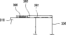
The 2nd cooling flowing path switching portion 360 can be bearing on the box body 310 with being free to slide, has cover 361 that the opening that will be on the recess 332 of the 2nd cover 330 forms clogs and as with the volute spring 366 of this cover 361 towards the force-applying piece of the glide direction application of force.
Cover 361 has the contact site 362 that contacts with the horizontal component of aforementioned recess 332, the sliding part 363 that has the edge chimeric, is provided with and slides along box body 310 perpendicular to the back side of contact site 362 with aforementioned grooves 333, with with the claw 364 of the preceding end in contact of extension 336, and form that section roughly is the T font and the front is roughly square shape.
One end of volute spring 366 is installed on the cover 361, and the other end inserts and is fixed in the recess 327 that forms on the extension 326 of the 1st cover 320.
As shown in Figure 9, for example, when box body 310 1 thrusters were pressed, cover 361 was opened, and presents the opening between the 1st cover 320 and the 2nd cover 330 with claw 364, and cooling air can be discharged or import.In case and hand is when breaking away from the claw 364 pushed, under the elastic force effect of volute spring 366, cover 361 automatically clogs opening.
Such light supply apparatus 413 can load and unload in the Bright Source Protection portion 471 as shown in figure 10.
The inside of this Bright Source Protection portion 471 has the roughly the same incorporating section 472 of shape and light supply apparatus 413, forms the box-shaped with the face upper shed of the opposite side of projection lens 46 sides.
In Figure 10, light supply apparatus 413 is that the opening 314 at box body 310 is configured under the state of right flank, is accommodated in the incorporating section 472 from the 2nd cover 330.That is to say that the end table portion 311 of box body 310 becomes the surface of revealing the outside.And, by taking in light supply apparatus 413 under the state that is disposed at right flank at opening 314, and under this state, take off light supply apparatus, but be formed at pair of openings portion 302 horizontal arrangement just on the lamp body 410 box body 310.
At the opening periphery of light guide therefor 47, form light supply apparatus 413 embedded in the recess 353 of the 1st cooling flowing path switching portion 350 that inserts when the incorporating sections 472 and on push away a pair of the 1st jut 475 of this recess 353.
Contact with the claw 364 of the 2nd cooling flowing path switching portion 360 when forming light supply apparatus 413 on the bottom surface 473 of incorporating section 472 and embedding in the incorporating sections 472 and on push away this claw 364 a pair of the 2nd jut 476 and be configured in 473 belows, bottom surface, the not shown opening 477 that is connected for the multiple-blade ring-type fan suction inlet of centrifugal fan.
When light supply apparatus 413 was accommodated in incorporating section 472, opening 477 was mutually opposed with the opening between the 1st cover 320 and the 2nd cover 330.In addition, the opening 474 that is formed at a side in face of this opening 477 can enter temperature and compare quite low air with reverberator 412 internal temperatures for flowing into the opening of light supply apparatus 413 periphery air.
Thereby, when light supply apparatus 413 being accommodated in (being installed on the projector 1) incorporating section 472, shown in Figure 11 (A), the 1st cooling flowing path switching portion 350 is automatically opened by the 1st jut 475, opens the cooling flowing path 340 in the box body 300, and is opposite, light supply apparatus 413 is taken off (taking off from projector 1) from incorporating section 472 when, shown in Figure 11 (B), under the elastic force effect of volute spring 356, automatically clog cooling flowing path 340.
Equally, when light supply apparatus 413 being accommodated in (being installed on the projector 1) incorporating section 472, shown in Figure 12 (A), the 2nd cooling flowing path switching portion 360 is automatically opened by the 2nd jut 476, opens the cooling flowing path 340 in the box body 300, and is opposite, light supply apparatus 413 is taken off (taking off from projector 1) from incorporating section 472 when, shown in Figure 12 (B), under the elastic force effect of volute spring 366, automatically clog cooling flowing path 340.
In addition, as shown in figure 13, in the projector 1, have also on the light supply apparatus 413 that installs to incorporating section 472 that front end inserts the 1st cooling flowing path switching portion 350 and cooling air imported square tube shape conduit 381 in this light supply apparatus 413.
The base end side (with the opposite side of the 1st cooling flowing path switching portion 350 sides) of this conduit 381 be provided with send cooling air to be the cooling fan 382 of centrifugal fan.
Therefore, in the present embodiment, the light supply apparatus 413 interior cooling airs that cooling fan 382 and conduit 381 are set flow into cooling flowing path 340 from the 1st cooling flowing path switching portion 350 towards the direction of the 2nd cooling flowing path switching portion 360.That is to say that the opening 312 of box body 310 becomes air importing opening, the opening that is opened and closed by the 2nd cooling flowing path switching portion 360 becomes air discharge opening.
Thus, for example, send into cooling air in the projector 1 reliably the illuminator 411 in the lead-in light source apparatus 413 with opening 221B etc. from aforementioned inlet hole 2A or handle.Then, the air of cooling light supply apparatus 413 inside is aspirated by the multiple-blade ring-type fan by being formed at the opening 474 on 472 bottom surfaces 473, incorporating section, and the gas outlet 390 by being connected with this multiple-blade ring-type fan, is discharged to outside the projector 1.
Adopt present embodiment, can obtain following effect.
Promptly, downcutting the recess 303 that forms because of pair of openings portion 302 by the part of the front-end edge that the light of reverberator 412 is penetrated direction constitutes, cooling air can be on the optical axis craspedodrome direction of reverberator 412, flow into further near the illuminator 411 as pyrotoxin, thus, cools light source lamp 411 effectively.
In addition, owing to form the cooling flowing path 340 that cooling air is imported illuminator 411 by pair of openings portion 302 on box body 300, cools light source lamp 411 effectively, improve the life-span of this illuminator 411.
In addition, owing to have the 1st, the 2nd cooling flowing path switching portion 350,360 that when taking off, clogs cooling flowing path 340 from projector 1, even in projector 1 uses, the luminotron of illuminator 411 breaks, when changing light supply apparatus 413, the fragmentation of luminotron can be not withered and fallen to outside yet, installs constantly at projector 1, because of the formation of these the 1st, the 2nd cooling flowing path switching portions 350,360, also can not reduce the cooling effectiveness of illuminator 411 for unlatching cooling flowing path 340.Have again, when taking off from projector 1, owing to be that light supply apparatus 413 is installed in the mode of horizontal direction configuration by pair of openings portion 302, when changing this light supply apparatus 413, can prevent reliably further that the luminotron fragmentation of illuminator 411 is withered and fallen to outside phenomenon.
In addition, owing to constitute the 1st, the 2nd cooling flowing path switching portion 350,360 by cover 351,361 and volute spring 356,366 respectively, just the switching portion of cooling flowing path 340 can be provided with on the box body 300 with simple structure, thus, be easy to the manufacturing of light supply apparatus 413.
Have again, owing between the 1st cover 320 and the 2nd cover 330, form conduit, in corresponding to projector 1 on the position of cooling flowing path 340, just can realize that cooling air imports, cooled air is discharged outside box body 300, can further improve the cooling effectiveness of light supply apparatus 413 outside box body 300.
In addition, owing to be respectively equipped with the dustproof filtrator of using in the pair of openings portion 302, even, can prevent reliably that also fragmentation is withered and fallen outside box body 300 just in case the luminotron of illuminator 411 breaks.In addition, be provided with membrane filter, can prevent that dust from invading along with the importing of cooling air in the light supply apparatus 413, can prevent the phenomenon that the pollution brightness because of luminotron reduces owing to import at air on the peristome 302 of usefulness.
Have again, in the projector 1 that light supply apparatus 413 is housed, owing on this light supply apparatus 413, be provided with the conduit 381 that imports cooling air, cooling air in the projector 1 is reliably in the lead-in light source apparatus 413, further improve the cooling effectiveness of light supply apparatus 413, prolonged the serviceable life of light supply apparatus 413.
Because of on conduit 381, being provided with cooling fan 382, can cooling air be sent in the cooling flowing path 340 forcibly by this conduit 381, can promote the circulation of cooling air, further improve the cooling effectiveness of light supply apparatus 413.
In addition, the present invention is not limited to previous embodiment, comprises other that can realize the object of the invention and constitutes etc., and variation shown below etc. is also contained among the present invention.
For example, in the aforementioned embodiment, be to be provided with cooling fan, but be not limited to this, for example, as shown in figure 14, be provided with the hole in the part of exhaust manifolds 390, this Kong Keyu connects the air of cooling device inside to the outside exhaust manifolds of discharging 383 of device.At this moment, the reverberator air outside that the air in the exhaust manifolds 390 and the air of reverberator inside and temperature are quite low is mixed, because of the reverberator temperature inside is lower, can obtain the abundant effect of cooling off.
In addition, in the aforementioned embodiment, be that the cooling fan inhaled air is sent into cooling flowing path 340 forcibly from conduit, and cooling air is discharged to projector 1 outside with the multiple-blade ring-type fan, but be not limited to this, for example, can will send into cooling flowing path 340 forcibly, cooling air be discharged to the projector outside with cooling fan by multiple-blade ring-type fan inhaled air.Like this, set cooling flowing path 340 from the 2nd cooling flowing path switching portion 350 to the mobile mode of the direction of the 1st cooling flowing path switching portion 360 with cooling air.
In addition, in the aforementioned embodiment, be provided with conduit, but be not limited to this, for example, as long as just can will just can in the abundant lead-in light source apparatus of cooling air with the opening of the 1st cooling flowing path switching portion 350 switchings.
In addition, in the previous embodiment, be on each of pair of openings portion, to be provided with dustproofly with filtrator, but be not limited to this, for example, only the air in pair of openings portion is provided with on importing and discharging with peristome with peristome or air.
Have again, in the aforementioned embodiment, between the 1st cover 320 and the 2nd cover 330, form conduit, but be not limited to this, for example, outside box body 300, import, cooled air discharged outside box body 300 just can as long as can realize cooling air effectively.
In the aforementioned embodiment, the 1st, the 2nd cooling flowing path switching portion has cover and volute spring, but is not limited to this; for example; as long as carry out the switching of cover in Bright Source Protection portion one side, volute spring not necessarily, its shape, constituting can be suitably definite according to performance.
In the aforementioned embodiment, used two kinds of cooling flowing path switching portions, but be not limited to this, can only use the 1st cooling flowing path switching portion 350, or only used the 2nd cooling flowing path switching portion 360, can suitably select according to shape, the formation of Bright Source Protection portion.
In the aforementioned embodiment, when taking off from projector, pair of openings portion is a horizontal direction setting, but is not limited to this, for example, and also can the vertical direction configuration.
In the aforementioned embodiment, pair of openings portion is downcut and the recess 303 that forms constitutes by the part of the front-end edge that the light of reverberator 412 is penetrated direction, but is not limited to this, and for example, the part that can downcut transparent panel forms.
As projector of the present invention, be not limited to use liquid crystal board for optic modulating device, for example, can adopt the optic modulating device that has the plasma element or use micromirror, the reflection type optical modulating device with reflection of the light of incident and modulation to penetrate, or adopt the optic modulating device of one-board, two pieces of formulas, rear portion type.Mainly be, the light beam that illuminator can be penetrated according to the picture information modulation forming optical image, and with the projector of this optical image enlarging projection just can, this constitutes etc. can be suitably definite according to performance.
Claims (17)
1, a kind of light supply apparatus, be used for light beam that illuminator is penetrated according to the picture information modulation with form optical image, and with the projector of this optical image enlarging projection, this light supply apparatus comprises illuminator, the reverberator that the light optically focused that this illuminator is radiated penetrates, with the box body of taking in described illuminator and described reverberator, it is characterized in that, the light outgoing plane of described reverberator is covered by transparent panel, and the optical axis that forms with described reverberator on the surface of contact of this transparent panel and described reverberator is the pair of openings portion of center, symmetric arrangement; Described box body has the cooling flowing path that cooling air is imported described illuminator by described pair of openings portion, with when taking off, clog this cooling flowing path from described projector, and when installing on the described projector, open the cooling flowing path switching portion of this cooling flowing path.
According to the described light supply apparatus of claim 1, it is characterized in that 2, described pair of openings portion is made of the recess that the light that is formed at described reverberator penetrates on the direction fore-end.
According to the described light supply apparatus of claim 1, it is characterized in that 3, described pair of openings portion is the horizontal direction setting when taking off from described projector.
According to the described light supply apparatus of claim 1, it is characterized in that 4, described cooling flowing path switching portion axle freely to rotate has cover that the opening on this box body is clogged and to the force-applying piece of this cover towards the gyratory directions application of force on described box body.
5, according to the described light supply apparatus of claim 1, it is characterized in that, described cooling flowing path switching portion can be bearing on the described box body with being free to slide, has cover that the opening that will form on this box body clogs and to the force-applying piece of this cover towards the glide direction application of force.
6, according to the described light supply apparatus of claim 1, it is characterized in that, form on the described box body air is imported described cooling flowing path and/or the conduit outside described cooling flowing path imports box body outside box body.
According to the described light supply apparatus of claim 1, it is characterized in that 7, described pair of openings portion is provided with the dustproof filtrator of using.
8, a kind of projector, has light supply apparatus, this light supply apparatus comprises illuminator, the reverberator that the light optically focused that this illuminator is radiated penetrates, with the box body of taking in described illuminator and described reverberator, it is characterized in that the light outgoing plane of described reverberator is covered by transparent panel, the optical axis that forms with described reverberator on the surface of contact of this transparent panel and described reverberator is the pair of openings portion of center, symmetric arrangement; Described box body has the cooling flowing path that cooling air is imported described illuminator by described pair of openings portion, with when taking off, clog this cooling flowing path from described projector, and when installing on the described projector, open the cooling flowing path switching portion of this cooling flowing path.
9, according to the described projector of claim 8, it is characterized in that having described light supply apparatus when installing, front end inserts described cooling flowing path switching portion and cooling air is imported the conduit of this light supply apparatus.
According to the described projector of claim 9, it is characterized in that 10, described conduit is provided with the fan of cooling air being sent into its cardinal extremity one side.
11, according to the described projector of claim 9, it is characterized in that having the air that the described device of cooling is inner to the outside exhaust manifolds of discharging of device, cardinal extremity one side of described conduit is connected with these exhaust manifolds.
12., it is characterized in that described pair of openings portion is made of the recess that the light that is formed at described reverberator penetrates on the direction fore-end according to the described projector of claim 8.
13., it is characterized in that described pair of openings portion is the horizontal direction setting according to the described projector of claim 8 when taking off from described projector.
14., it is characterized in that described cooling flowing path switching portion axle freely to rotate has cover that the opening that will form on this box body clogs and to the force-applying piece of this cover towards the gyratory directions application of force on described box body according to the described projector of claim 8.
15. according to the described projector of claim 8, it is characterized in that, described cooling flowing path switching portion can be bearing on the described box body with being free to slide, has cover that the opening that will form on this box body clogs and to the force-applying piece of this cover towards the glide direction application of force.
16. according to the described projector of claim 8, it is characterized in that, form on the described box body air is imported described cooling flowing path and/or the conduit outside described cooling flowing path imports box body outside box body.
17., it is characterized in that described pair of openings portion is provided with the dustproof filtrator of using according to the described projector of claim 8.
Applications Claiming Priority (3)
| Application Number | Priority Date | Filing Date | Title |
|---|---|---|---|
| JP299639/2000 | 2000-09-29 | ||
| JP2000299639A JP3664065B2 (en) | 2000-09-29 | 2000-09-29 | Light source device and projector |
| JP299639/00 | 2000-09-29 |
Publications (2)
| Publication Number | Publication Date |
|---|---|
| CN1344968A CN1344968A (en) | 2002-04-17 |
| CN1174284C true CN1174284C (en) | 2004-11-03 |
Family
ID=18781419
Family Applications (1)
| Application Number | Title | Priority Date | Filing Date |
|---|---|---|---|
| CNB01141040XA Expired - Fee Related CN1174284C (en) | 2000-09-29 | 2001-09-29 | Light source device and projector |
Country Status (7)
| Country | Link |
|---|---|
| US (2) | US6698899B2 (en) |
| EP (1) | EP1195640B1 (en) |
| JP (1) | JP3664065B2 (en) |
| KR (1) | KR100445038B1 (en) |
| CN (1) | CN1174284C (en) |
| DE (1) | DE60108030T2 (en) |
| TW (1) | TW562913B (en) |
Families Citing this family (56)
| Publication number | Priority date | Publication date | Assignee | Title |
|---|---|---|---|---|
| JP3512745B2 (en) * | 2001-01-18 | 2004-03-31 | 松下電器産業株式会社 | Light source device and projector using the same |
| TW514352U (en) * | 2002-03-22 | 2002-12-11 | Coretronic Corp | Heat sink for light machine imaging assembly |
| KR100476464B1 (en) * | 2002-08-09 | 2005-03-17 | (주)강산조명 | A street lamp |
| JP3829813B2 (en) | 2003-02-25 | 2006-10-04 | セイコーエプソン株式会社 | projector |
| JP4093192B2 (en) | 2003-03-25 | 2008-06-04 | セイコーエプソン株式会社 | Light source device and projector |
| JP3855955B2 (en) | 2003-03-28 | 2006-12-13 | セイコーエプソン株式会社 | Light source device and projector |
| JP2005189653A (en) | 2003-12-26 | 2005-07-14 | Olympus Corp | Image projector |
| US6995837B1 (en) * | 2004-02-10 | 2006-02-07 | Retina Systems Inc. | Optical inspection system and method of use |
| JP4511269B2 (en) * | 2004-07-21 | 2010-07-28 | 三洋電機株式会社 | Projection display device |
| JP4196913B2 (en) | 2004-09-14 | 2008-12-17 | ソニー株式会社 | Projector device |
| US7125125B2 (en) | 2004-09-15 | 2006-10-24 | Coretronic Corporation | Burner debris collection apparatus for projectors |
| CN100416404C (en) * | 2004-11-04 | 2008-09-03 | 精工爱普生株式会社 | Optical device and projector |
| JP4221353B2 (en) * | 2004-11-19 | 2009-02-12 | Necディスプレイソリューションズ株式会社 | Light source device and projection display device |
| JP3995685B2 (en) * | 2004-12-24 | 2007-10-24 | 三洋電機株式会社 | Projection display device |
| EP1688787A1 (en) | 2005-02-07 | 2006-08-09 | Coretronic Corporation | Burner debris collection apparatus for projectors |
| JP4656973B2 (en) | 2005-03-16 | 2011-03-23 | 三菱電機株式会社 | Light source device and projection display device |
| TW200639566A (en) * | 2005-05-10 | 2006-11-16 | Young Optics Inc | Heat dissipation structure for projector |
| JP4502885B2 (en) * | 2005-06-01 | 2010-07-14 | 三洋電機株式会社 | Projection display |
| JP4225991B2 (en) * | 2005-07-29 | 2009-02-18 | 三洋電機株式会社 | Projector device |
| JP4491406B2 (en) | 2005-11-18 | 2010-06-30 | Necディスプレイソリューションズ株式会社 | Lamp cooling structure, projection display device, and lamp cooling method |
| KR100766075B1 (en) * | 2005-12-05 | 2007-10-11 | 삼성전자주식회사 | Digital micro-mirror device assembly and optical projection system using the same |
| TWI290261B (en) * | 2006-01-20 | 2007-11-21 | Benq Corp | Air guiding structure and projecting device incorporating the same |
| JP4914077B2 (en) * | 2006-02-07 | 2012-04-11 | キヤノン株式会社 | Projection type image display device |
| TW200734573A (en) * | 2006-03-03 | 2007-09-16 | Benq Corp | Equipment capable of adjusting height |
| JP2007248753A (en) * | 2006-03-15 | 2007-09-27 | Funai Electric Co Ltd | Projection device |
| JP2007272040A (en) * | 2006-03-31 | 2007-10-18 | Funai Electric Co Ltd | Projector |
| JP2007322823A (en) | 2006-06-01 | 2007-12-13 | Funai Electric Co Ltd | Projector |
| JP4985069B2 (en) * | 2007-04-12 | 2012-07-25 | ソニー株式会社 | Projection display |
| KR101079582B1 (en) * | 2007-05-18 | 2011-11-03 | 삼성전자주식회사 | Image forming apparatus capable of reducing temperature difference of image receptor |
| TWI337295B (en) * | 2007-06-29 | 2011-02-11 | Delta Electronics Inc | Housing assembly and projection device having the same |
| US9140968B2 (en) * | 2007-06-29 | 2015-09-22 | Seiko Epson Corporation | Projection device particle-containment shield |
| CN101344710B (en) * | 2007-07-09 | 2010-12-29 | 台达电子工业股份有限公司 | Case assembly and projection device using the same |
| KR101370911B1 (en) * | 2007-10-23 | 2014-03-10 | 엘지전자 주식회사 | thin type projector |
| KR100968276B1 (en) * | 2008-02-13 | 2010-07-06 | 가자마 이엔티 (주) | Medical Apparatus For Wall Tapestry |
| TW201102745A (en) * | 2009-07-15 | 2011-01-16 | Qisda Corp | Projector |
| JP2011033747A (en) * | 2009-07-31 | 2011-02-17 | Seiko Epson Corp | Projector, program, information storage medium and cooling control method |
| JP2011141395A (en) * | 2010-01-06 | 2011-07-21 | Sanyo Electric Co Ltd | Projection type video display apparatus |
| TWI434124B (en) * | 2010-09-16 | 2014-04-11 | Delta Electronics Inc | Guiding device and projector comprising the same |
| KR20130033736A (en) | 2011-09-27 | 2013-04-04 | 삼성전자주식회사 | Projector and display apparatus havinh the same |
| JP5945900B2 (en) | 2011-11-04 | 2016-07-05 | 株式会社リコー | Image projection device |
| JP5641441B2 (en) * | 2011-11-04 | 2014-12-17 | 株式会社リコー | Image projection device |
| USD722383S1 (en) | 2012-05-01 | 2015-02-10 | Carol Cole Company | Skin clearing and toning device |
| CN203883953U (en) * | 2014-04-22 | 2014-10-15 | 深圳市绎立锐光科技开发有限公司 | Dustproof and heat-radiation module of color wheel and light source system |
| USD739541S1 (en) | 2014-05-12 | 2015-09-22 | Carol Cole Company | Skin clearing and toning device |
| CN103995423A (en) * | 2014-05-22 | 2014-08-20 | 无锡启晖光电科技有限公司 | Blast resistant structure of projector lamp bulb |
| WO2016009618A1 (en) * | 2014-07-15 | 2016-01-21 | セイコーエプソン株式会社 | Light source device, dust collecting member and projector |
| USD752237S1 (en) | 2015-03-03 | 2016-03-22 | Carol Cole Company | Skin toning device |
| CN105159016A (en) * | 2015-10-30 | 2015-12-16 | 广西中才铝业有限公司 | Projector shell |
| CN108205234A (en) * | 2016-12-16 | 2018-06-26 | 张宗伟 | A kind of indoor projection arrangement of meeting |
| USD854699S1 (en) | 2018-05-15 | 2019-07-23 | Carol Cole Company | Elongated skin toning device |
| JP6740541B1 (en) * | 2019-04-25 | 2020-08-19 | 日本電気株式会社 | Input/output device and method of gripping input/output device |
| USD953553S1 (en) | 2020-02-19 | 2022-05-31 | Carol Cole Company | Skin toning device |
| USD944310S1 (en) * | 2020-03-05 | 2022-02-22 | Gdc Technology (Shenzhen) Limited | Projector system |
| USD944882S1 (en) * | 2020-07-21 | 2022-03-01 | Panasonic Intellectual Property Management Co., Ltd. | Projector |
| USD957664S1 (en) | 2020-07-29 | 2022-07-12 | Carol Cole Company | Skin toning device |
| USD999810S1 (en) * | 2022-01-11 | 2023-09-26 | Shenzhen Oceanwing Smart Innovations Technology Co., Ltd | Laser projector |
Family Cites Families (17)
| Publication number | Priority date | Publication date | Assignee | Title |
|---|---|---|---|---|
| DE4238731A1 (en) | 1992-11-17 | 1994-05-19 | Barbara Joerns | Dual projection device with central single light source - has housing panels defining parallel cooling channels for counter-flow cooling of light source |
| US5568007A (en) * | 1993-07-28 | 1996-10-22 | Jasco Corporation | Lamp unit and optical analyzer using the same |
| US5622418A (en) * | 1994-03-29 | 1997-04-22 | Mitsubishi Denki Kabuskiki Kaisha | Projection display device |
| TW323345B (en) * | 1994-07-08 | 1997-12-21 | Fujitsu Ltd | |
| EP1310805B1 (en) * | 1994-12-27 | 2006-05-17 | Seiko Epson Corporation | Prism unit and projection type display device using it |
| JP3976812B2 (en) | 1995-03-09 | 2007-09-19 | セイコーエプソン株式会社 | Polarized illumination device and projection display device |
| JP3307226B2 (en) * | 1995-11-01 | 2002-07-24 | 松下電器産業株式会社 | Lamp equipment for liquid crystal projection equipment |
| EP1327906B1 (en) * | 1996-10-04 | 2005-08-17 | Seiko Epson Corporation | Projection display |
| JPH10254061A (en) | 1997-03-07 | 1998-09-25 | Seiko Epson Corp | Light source device and projection type display device |
| JP3841950B2 (en) | 1998-02-24 | 2006-11-08 | 三菱電機株式会社 | Lamp box and projector device |
| JPH11329015A (en) * | 1998-05-13 | 1999-11-30 | Sony Corp | Light source lamp device |
| JP2000056396A (en) | 1998-08-04 | 2000-02-25 | Mitsubishi Electric Corp | Projector device and lamp box |
| JP2000200511A (en) | 1998-10-30 | 2000-07-18 | Phoenix Denki Kk | Discharge lamp |
| US6481854B1 (en) * | 1998-12-28 | 2002-11-19 | Fujitsu Limited | Projection type display apparatus having air cooling arrangement |
| US6398367B1 (en) * | 1999-03-05 | 2002-06-04 | Seiko Epson Corporation | Light source device and projector using the light source device |
| JP2001133885A (en) * | 1999-08-26 | 2001-05-18 | Mitsubishi Electric Corp | Projector |
| US6398366B1 (en) * | 1999-10-15 | 2002-06-04 | Sony Corporation | Image display apparatus of the projection type |
-
2000
- 2000-09-29 JP JP2000299639A patent/JP3664065B2/en not_active Expired - Fee Related
-
2001
- 2001-09-24 US US09/960,374 patent/US6698899B2/en not_active Expired - Lifetime
- 2001-09-26 TW TW090123762A patent/TW562913B/en not_active IP Right Cessation
- 2001-09-27 DE DE60108030T patent/DE60108030T2/en not_active Expired - Lifetime
- 2001-09-27 EP EP01308217A patent/EP1195640B1/en not_active Expired - Lifetime
- 2001-09-28 KR KR10-2001-0060357A patent/KR100445038B1/en not_active IP Right Cessation
- 2001-09-29 CN CNB01141040XA patent/CN1174284C/en not_active Expired - Fee Related
-
2003
- 2003-12-09 US US10/730,045 patent/US6902275B2/en not_active Expired - Fee Related
Also Published As
| Publication number | Publication date |
|---|---|
| US6902275B2 (en) | 2005-06-07 |
| KR100445038B1 (en) | 2004-08-18 |
| KR20020025787A (en) | 2002-04-04 |
| CN1344968A (en) | 2002-04-17 |
| JP3664065B2 (en) | 2005-06-22 |
| DE60108030D1 (en) | 2005-02-03 |
| JP2002107823A (en) | 2002-04-10 |
| US20040114113A1 (en) | 2004-06-17 |
| EP1195640A1 (en) | 2002-04-10 |
| EP1195640B1 (en) | 2004-12-29 |
| DE60108030T2 (en) | 2005-12-29 |
| US6698899B2 (en) | 2004-03-02 |
| US20020039174A1 (en) | 2002-04-04 |
| TW562913B (en) | 2003-11-21 |
Similar Documents
| Publication | Publication Date | Title |
|---|---|---|
| CN1174284C (en) | Light source device and projector | |
| CN1174283C (en) | Projector | |
| CN1223895C (en) | Projector light source and projection image display equipment with the lignt source | |
| CN2682450Y (en) | Light source device and projector | |
| CN1704839A (en) | Projection-type image display apparatus | |
| CN1661464A (en) | Light source device and projector | |
| CN1942700A (en) | Light source device, illumination optical device, and display device | |
| CN1627181A (en) | Light source device and projector apparatus having same | |
| CN1527129A (en) | Ventilating duct, cooling device and projector | |
| CN107490928B (en) | Fluorescent light emitting device, light source device, and image projection device | |
| CN1463387A (en) | Projector | |
| CN1900816A (en) | Projector device | |
| CN1203366C (en) | Optical part mounting structure and projector | |
| CN101063795A (en) | Optical device and projector equipped with the same | |
| CN1873521A (en) | Optical modulation element unit, projection optical unit, and image projection apparatus | |
| CN1658064A (en) | Optical device and projector | |
| CN1834777A (en) | Light source device and projection-type image display device | |
| CN1310086C (en) | Case for optical element, optical device and projector | |
| CN1573521A (en) | Cooling device and optical device and projector having the cooling device | |
| CN1610862A (en) | Projector | |
| CN1873520A (en) | Projection display | |
| CN1534375A (en) | Light source apparatus and projector | |
| CN1754123A (en) | Optical component casing, optical device and projector | |
| CN1244835C (en) | Polarized light converting device, lighting optical device and projector | |
| CN1530736A (en) | Light source device and projector |
Legal Events
| Date | Code | Title | Description |
|---|---|---|---|
| C10 | Entry into substantive examination | ||
| SE01 | Entry into force of request for substantive examination | ||
| C06 | Publication | ||
| PB01 | Publication | ||
| C14 | Grant of patent or utility model | ||
| GR01 | Patent grant | ||
| CF01 | Termination of patent right due to non-payment of annual fee | ||
| CF01 | Termination of patent right due to non-payment of annual fee |
Granted publication date: 20041103 Termination date: 20160929 |