CN1172964A - Athermal LCD projection lens - Google Patents
Athermal LCD projection lens Download PDFInfo
- Publication number
- CN1172964A CN1172964A CN97102617A CN97102617A CN1172964A CN 1172964 A CN1172964 A CN 1172964A CN 97102617 A CN97102617 A CN 97102617A CN 97102617 A CN97102617 A CN 97102617A CN 1172964 A CN1172964 A CN 1172964A
- Authority
- CN
- China
- Prior art keywords
- lens
- projection lens
- projection
- parts
- image
- Prior art date
- Legal status (The legal status is an assumption and is not a legal conclusion. Google has not performed a legal analysis and makes no representation as to the accuracy of the status listed.)
- Pending
Links
Images


Classifications
-
- G—PHYSICS
- G02—OPTICS
- G02B—OPTICAL ELEMENTS, SYSTEMS OR APPARATUS
- G02B13/00—Optical objectives specially designed for the purposes specified below
- G02B13/16—Optical objectives specially designed for the purposes specified below for use in conjunction with image converters or intensifiers, or for use with projectors, e.g. objectives for projection TV
-
- G—PHYSICS
- G02—OPTICS
- G02B—OPTICAL ELEMENTS, SYSTEMS OR APPARATUS
- G02B1/00—Optical elements characterised by the material of which they are made; Optical coatings for optical elements
- G02B1/04—Optical elements characterised by the material of which they are made; Optical coatings for optical elements made of organic materials, e.g. plastics
- G02B1/041—Lenses
-
- G—PHYSICS
- G02—OPTICS
- G02B—OPTICAL ELEMENTS, SYSTEMS OR APPARATUS
- G02B7/00—Mountings, adjusting means, or light-tight connections, for optical elements
- G02B7/02—Mountings, adjusting means, or light-tight connections, for optical elements for lenses
- G02B7/028—Mountings, adjusting means, or light-tight connections, for optical elements for lenses with means for compensating for changes in temperature or for controlling the temperature; thermal stabilisation
Abstract
A four element, athermalized projection lens for use in forming an enlarged color image of a LCD panel is disclosed. The powers of the elements from the screen to the LCD are negative/positive/negative/positive and the dispersions are low dispersion/low dispersion/high dispersion/low dispersion. The first three elements are composed of plastic and the last element is composed of glass. The projection lens exhibits a high level of aberration correction over magnifications ranging from about 5x to about 12x. The four element design comprises the minimum number of elements capable of achieving a relatively long back focal length, athermalization, and lateral color correction of less than about half a pixel.
Description
The present invention relates to a kind of projection lens, relate in particular to the projection lens that can be used to form the target image of forming by pixel (for example liquid crystal display (LCD)).
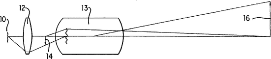
Projection lens system (being also referred to as " optical projection system " herein) is used for forming target image on viewing screen.Fig. 4 shows the basic structure of this system, wherein 10 is light source (for example tungsten halogen lamps), the 12nd, the illumination optical device, it forms the picture (hereinafter being referred to as " output " of irradiation system) of light source, the 14th, treat the target (for example, LCD switching plate pel array) of projection, the 13rd, projection lens, it is made up of a plurality of lens units, forms the enlarged image of target 14 on viewing screen 16.
Target is that the projection lens system of LCD or other pixel plate (pixelized panel) is used for various application, comprises data presentation system.This projection lens system preferably uses single projection lens, and its forms for example has the veneer image of red, green, blue or the image that formation has three blocks of independent plates, one in every kind of color.For convenience of explanation, following discussion will be carried out the projection lens system that uses monolithic LCD plate, should be understood that the present invention also can be used to use the system of polylith plate or other pixelation type.
Need projection lens to use with the LCD plate, these lens have following characteristic at least simultaneously: the focal length that (1) is long, and for example, focal length is greater than the full-size of bigger LCD plate, and for example the full-size of LCD plate is approximately greater than 10 centimetres; (2) than long back focal length, for example back focal length is greater than the eyeglass focal length; (3) senior colour correction; (4) low distortion; (5) when keeping the output of being coupled to irradiation system expeditiously and senior aberration correction, can under various magnifications, carry out work; (6) low to the sensitivity of temperature variation; (7) lens unit of minimum number, their major parts are made of plastics, so that the total cost of system is minimum.
Requiring long-focus is because it can use bigger LCD plate, for example width is greater than the plate of 10cm, such as the plate of those width on the 20cm order of magnitude, still the field angle of projection lens is maintained in the controllable scope simultaneously, for example in the scope of 50 degree-60 degree (whole audience).Require big LCD plate to be because they can provide higher resolution when using less pixel, or they make manufacturing become easier when using bigger pixel.
Require long back focal length, promptly last lens surface is from the distance of LCD plate, be since it can make the output of irradiation system be in projection lens near, make the output distance bigger.Requiring bigger output distance is because they provide less angle of incidence of light on the LCD plate.
Senior colour correction is important, and this is because fog or under extreme case in pixel, and pixel when image comes off, can easily be seen aberration fully on the image of pixel plate.These problems generally become the most serious at the edge of the ken.Usually, the colour correction of measuring on the LCD plate should be better than about half-pixel, and avoiding these problems, for example colored correction should be preferably be about 200 microns good about 100 microns of pixel than feature size.
The all aberration of system need carry out addressing, and look laterally colored, coma changes and the astigmatism aberration generally is the most complicated.Laterally colored, promptly the magnification change that changes with colour especially bothers, because it reduces appearing as contrast itself, especially at the edge of visual field.Under opposite extreme situations, can in the scope of full visual field, see the rainbow effect.
In the optical projection system of using cathode-ray tube (CRT), can be by for example reducing the image size that on red CRT face, produces with respect to the image size that produces on the blue CRT face, it is laterally colored to compensate a spot of (remaining) by the mode of electronics.Yet for the plate of pixelation, this adjusting can not be carried out, and this is because image digitizing, so can not carry out level and smooth adjustment on the size of full visual field.Therefore need senior horizontal colored the correction for this projection lens.
It should be noted that the increase along with the projection lens focal length, aberration becomes and more is difficult to revise.Therefore, preceding two kinds of criterions discussed above, i.e. long-focus and high grade colorful correction is contradiction each other in realizing suitable lens design.
Use pixel plate to come video data to cause pressing for correcting distorted.This is because also need the preferable image quality when watching data even on the extreme point of eyeglass visual field.Will understand that it is important that numeral that shows in field of view edge or alphabetical image do not distort and show as heart place therein.And projection lens usually uses the LCD plate of skew, so the distortion on the viewing screen not for the horizontal line symmetry by screen center, but for example increases to the top from bottom of screen monotonously.This result makes the beholder can easily watch or even a spot of deformation.
Need the projection lens that can work effectively with various magnifications, this is because it can make optical projection system be used for the screen of different size, and does not need to change any system unit.Only target and figure image conjugate need to change, and this can easily realize by moving eyeglass with respect to the LCD plate.Certainly, problem is will provide in the output of effectively being coupled to irradiation system, and provides senior aberration correction in whole magnification scope.
In order to produce the image with enough brightness, most of light must pass through projection lens.Therefore, generally between room temperature and eyeglass working temperature, there is the significant temperature difference.In addition, eyeglass needs and can work under multiple environmental baseline.For example, projection lens system usually is installed on the ceiling in the room that constitutes the buildings roof, and environment temperature may be more than 40 ℃.In order to overcome this influence, need a kind of its optical property to the insensitive projection lens of temperature variation.
A kind of method that overcomes the temperature sensitivity problem is to use the lens component of being made by glass.Compare with plastics, the radius-of-curvature of glass component and change of refractive are generally littler than the plastic components.Yet, especially carry out aberration when control in the needs aspheric surface, glass component usually than the plastic components costliness many.Equally, also wish to constitute lens design with a spot of lens component, this is that parts are few more just to mean that the total cost of lens systems is low more because the same with the use plastics.
The projection lens that describes below has reached above-mentioned all requirements, and can successfully be used for producing projection lens system cheaply, and this system can produce the image of the pixel plate of high-quality colour on viewing screen.
In the various below patents projection lens that uses with pixel plate has been described, the U.S. Patent No. 4 that comprises Taylor, 189,211, people's such as Tanaka U.S. Patent No. 5,042,929, people's such as Yano U.S. Patent No. 5,179,473, the U.S. Patent No. 5,200 of Moskovich, 861, the U.S. Patent No. 5 of Moskovich, 218,480, people's such as Iizuka U.S. Patent No. 5,278,698, the U.S. Patent No. 5 of Bentensky, 313,330, and the U.S. Patent No. 5 of Yano, 331,462.Can be to the argumentation of LCD system, and the EPO of EUROPEAN PATENT OFFICE patent gazette No.311 in people's such as Gagnon U.S. Patent No. 4,425,028, the U.S. Patent No. 4,461,542 of Gagnon, the U.S. Patent No. 4,826,311 of Ledebuhr, find in 116.
From above, the object of the present invention is to provide a kind of improved projection lens that uses with the LCD plate, it has seven kinds of each performances that requires in the performance discussing above simultaneously.This purpose is to realize by making projection lens comprise following parts by the order of (promptly growing conjugation side to its short conjugation side from it) from its image-side to its target side:
(a) first lens component has negative focal power, is made up of the plastic material with low chromatic dispersion (for example polypropylene);
(b) second lens component has positive focal power, is made up of the plastic material with low chromatic dispersion (for example polypropylene);
(c) prismatic glasses parts have negative focal power, are made up of the plastic material with high chromatic dispersion (for example styrene);
(d) the 4th lens component is made up of the plastic material with low chromatic dispersion (for example styrene, preferably crown glass).
In some preferred embodiment of the present invention, each parts in first, second and the prismatic glasses parts have an aspheric surface at least, and preferably each parts has two aspheric surfaces.In other preferred embodiment, the 4th lens component has sphere, and is made up of glass.In also having some preferred embodiments, the 4th lens component has positive focal power, and the combined light focal power of third and fourth parts is for negative.
In most preferred embodiment of the present invention, projection lens is made of above-mentioned four kinds of eyeglasses.
Projection lens of the present invention is designed to the outgoing position of irradiation system is used as the pseudo-aperture stop/entrance pupil (U.S. Patent No. 5,313,330 referring to Betensky is included in this by reference to the relevant portion of this patent) of projection lens preferably.Like this, can between output of the light of irradiation system and projection lens, realize effectively coupling.
According to these aspects, the invention provides a kind of projection lens system that forms target image, it comprises:
(a) irradiation system comprises light source and forms the optical devices of the irradiation usefulness of light source picture, and described similarly is the output of irradiation system;
(b) pixel plate, LCD plate for example, it includes target; And
(c) projection lens of the above-mentioned type, described projection lens has entrance pupil, and its position corresponds essentially to the position of irradiation system output.
In some preferred embodiment, by changing the distance between last lens surface of projection lens and the pixel plate, keep the entrance pupil of eyeglass to be fixed on basically on the position of irradiation system output simultaneously, can change the magnification of projection lens system.
It is not have heat basically that projection lens of the present invention also is designed to.Will go through as following, this is all to use by all projection lens to have the glass lens parts that are essentially the positive and negative focal power and realize.Like this, because the variation of the focal power of the positive lens component that temperature variation causes can compensate by the focal power that changes negative lens component, therefore when its temperature variation, also can make the overall optical property of projection lens constant substantially.
Figure 1A, 2A and 3A are the side view outline of the projection lens of formation according to the present invention.
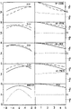
Figure 1B-1 is to 1D-4, the projection lens that 2B-1 to 2D-4 and 3B-1 to 3D-4 show Figure 1A, 2A and 3A respectively image to the magnification of target for-0.190 ,-0.130 and-0.083 (corresponding target to image magnification ratio for-5.3X ,-7.7X and-performance that calculates on 12X).
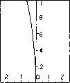
Fig. 1 E-1 to 1E-2 shows the projection lens of Figure 1A on thin scale image is-0.130 the colour correction and the performance that distorts to target magnification.
Fig. 4 is the synoptic diagram that can use the overall projection lens system of projection lens of the present invention.
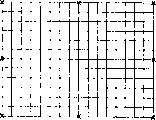
The parameter of Figure 1B-1 to 1E-2,2B-1 to 2D-4 and 3B-1 to 3D-4 has been shown in table 5.All B-1, C-1 and D-1 figure and Fig. 1 E-2 show radial distortion, and all B-2, C-2 figure and D-2 show for the distortion of square matrix on viewing screen.All B-3, C-3 and D-3 figure and Fig. 1 E-2 show the lateral chromatic aberration with respect to the entrance pupil coordinate, and wherein, solid line is represented the TAN data, and dash line is represented the SAG data, and dotted line is represented the SAG-Y data.Table 6 has been listed the wavelength of circle among these figure, triangle and square expression.All B-4, C-4 and D-4 illustrate the monochromatic optical transport function, left part shows and runs through focus data, right part to show wavelength be that 0.546 focus is to frequency data, its dotted line is represented the PHASE data, and dash line is represented the SAG data, and solid line is represented the TAN data.Table 7 has been listed the At focal position.
These figure incorporate in the instructions, and become the part of instructions, and they show preferred embodiment of the present invention, and are used from explanation principle of the present invention with description one.Of course it is to be understood that these figure and describing all is example, is not limitation of the present invention.
As mentioned above, projection lens of the present invention comprises the lens component with high chromatic dispersion and low chromatic dispersion, and the order of parts is counted from image-side and is low chromatic dispersion/low chromatic dispersion/high chromatic dispersion/low chromatic dispersion.
In general, high chromatic dispersion material is a kind of material with the chromatic dispersion that resembles flint glass, and low chromatic dispersion material is a kind of material with the chromatic dispersion that resembles crown glass.Especially, high chromatic dispersion material is the material of the scope from 20 to 50 of from 1.85 to 1.5 o'clock its V values of those ranges of indices of refraction, and low chromatic dispersion material is when to be those ranges of indices of refraction identical, the material of its V value scope from 35 to 75.
For the glass lens parts, the low chromatic dispersion and the high chromatic dispersion material of selection are respectively polypropylene and styrene.Certainly if desired, other plastics also can use.For example, polycarbonate and polystyrene have the character similar to the flint glass chromatic dispersion with polyacrylic multipolymer (for example NAS), can be used for replacing styrene.Referring to " the glass lens handbook, and the U.S. accurate eyeglass company limited (Precision Lens, Inc.), nineteen eighty-three, 17-29 page or leaf.
An importance of projection lens of the present invention is that they are not have heat, and promptly the optical property of system (especially comprising the distance (" back focal length ") between last a slice lens surface of lens set and the LCD plate) is not heated to its working temperature with projection lens from room temperature basically and changes.Especially, the variable quantity of back focal length is preferably less than the degree that makes the modulation transfer function (MTF) marked change, and for example, this variation should be less than about 5%.For the example of following mask body, this MTF criterion changes less than being about 0.2 millimeter corresponding to back focal length.Desired eyeglass focus is thermally-stabilised to be to realize by the eyeglass in selection and the layout glass lens parts.
Usually, use the glass lens parts that shortcoming is arranged, promptly the refractive index of plastic optics material is very remarkable with variation of temperature.Another influence is the variation of shape, and promptly the plastic optics material is with temperature expansion or contraction.The latter's influence does not have change of refractive remarkable like that usually.
If in eyeglass, only use low power glass lens parts, then might reach balance between the thermal distortion of the plastics of systems such as the thermal distortion of glass lens and for example eyeglass lens barrel or aluminium matter mechanical part, the eyeglass lens barrel is normally caused the root of the main mechanical aspects of focal variation by heat.In design, do not limit the use optical plastic, can use the advantage of the glass lens parts of high light focal power to be,, can make ability (performance) maximum of specific lens design with non-spherical optical surface (aspheric surface) because that the glass lens parts are easy to is molded.Use high light focal power plastic components also to cause the overall cost of eyeglass lower.
If clean plastics focal power is very important in design, then need not have thermalization (athermalization), perhaps will change when eyeglass temperature focus of eyeglass when room temperature changes to its working temperature.Especially like this for projector, it must be delivered to a large amount of light on the viewing screen, so its working temperature will be significantly greater than room temperature.
For projection lens of the present invention, no thermalization is achieved in that promptly, makes positive and negative plastics focal power balance, also considers the marginal ray height on glass lens position component and those parts simultaneously.
With regard to the glass lens parts that glass lens position component with regard to the temperature variation that is subjected to and the parts change of refractive amount that takes place thus is very important.Usually, the temperature variation that is subjected near the parts of the picture of light source or light source is bigger.In the practice, the Temperature Distribution in the zone that the measurement projection lens will be in when the light source illumination optical device relevant with it worked, the value that those are recorded is used to design projection lens then.
Whether the change of refractive of the marginal ray height of given thermal distortion particular plastic lens component being determined parts is remarkable with respect to the overall thermal stability of eyeglass.The parts that the marginal ray height is little, for example near the parts the system focus are generally little to the influence of the influence of the overall thermal stability of the system parts bigger than marginal ray height.
According to above-mentioned consideration, no thermalization is achieved in that promptly the temperature variation that is subjected to according to these parts of hope and the marginal ray height of these parts regulate the contribution of specific features, with the positive negative power in the balance glass lens parts.In the practice, this no thermalization process is attached in the following computerized lens design program.At first, under first Temperature Distribution, carry out ray trace, and calculate back focal length.Ray trace can be the paraxial ray trcaing for marginal ray.The second, under second Temperature Distribution, carry out identical ray trace, and calculate back focal length once more.First still to be that second Temperature Distribution need not keep on whole camera lens invariable, but in the ordinary course of things, it can change to another lens component from a lens component.With the system design of lens design program optimization the time, the back focal length that calculates is fixed to a constant then.
The mechanical hook-up that should be noted that such scheme hypothesis projection lens and LCD plate has kept last lens surface and the distance between the LCD plate not to change with the variation of system temperature basically.If can not guarantee this hypothesis, then can take other measure not have thermalization, for example, can be included in the measured value of the rate of travel of mechanical hook-up in this process, it is mechanically fixing perhaps another distance (distance for example between mirror surface and the LCD plate) being assumed.
Figure 1A, 2A and 3A show the various projection lens that constitute according to the present invention.The specification requirement of corresponding eyeglass has been shown in to 3 at table 1 respectively.In these figure, lens component and lens surface are used " L " and " S " numeral respectively.
As the way of custom, the left side of the accompanying drawing long conjugation of drawing, and the short conjugation of drawing on the right side.Therefore, in general application of the present invention, viewing screen is on the left side, and the LCD plate is on the right side.Figure 1A shows a kind of LCD plate, and for the camera lens of Fig. 2 A and 3A, have similar relative position.
Listed glass and the plastics quoted among the table 1-3 in table 4, wherein the glass title is the HOYA board.The equivalent material that other manufacturer makes also can be used for the present invention.
Asphericity coefficient listed in the table is used for following formula:
Wherein, z is for be that the surperficial sag (sag) of y, c are the curvature of eyeglass at the optical axis place counting distance from systematic optical axis, and k is the constant of the cone, and except pointed in table, its value is zero.
Abbreviation used among the table 1-3 is as follows: the OBJ.HT-object height; The f/-f-number; The MAG-magnification; The STOP-aperture stop; The EFL-effective focal length; Vertex distance before the FVD-; The ENP-entrance pupil; The IMD-image distance; The BRL-optical tube length; The EXP-emergent pupil; The OBD-object distance; OVL-length overall, the value that wherein provides are the situations that the left side of light from figure is transferred to the right.
Symbol " a " the expression aspheric surface relevant with each surface, the non-vanishing aspheric surface of symbol " ac " expression constant of the cone value.Surface 5 in the table 1 and the surface 3 in the table 3 are corresponding to the position (not illustrating among the figure) of halation aperture (vignetting aperture).All sizes that provide among the table 1-3 are to be unit with the millimeter.
As mentioned above, projection lens of the present invention designs with the pseudo-aperture stop/entrance pupil technology of the U.S. Patent No. 5,313,330 of Betensky.Surface 9 in the table 2 and the surface in table 1 and 3 10 constitute pseudo-aperture stop.Its position is corresponding to the outgoing position of irradiation system.
As be labeled as and can see in the sublist of " variable interval ", the distance from pseudo-aperture stop to the LCD plate, promptly " image distance " is constant for all focal positions (magnification) substantial constant of projection lens system.On the contrary, the interval 9 in the interval in the table 28 and the table 1 and 3 is with different magnification change.In some cases, exporting this corresponding to the irradiation that is positioned at the interval that is limited by lens surface before and after the eyeglass is spaced apart negative.
About no thermalization, should be noted that the power value of second lens component is greater than the power value of each eyeglass in first, third and fourth eyeglass for every kind of listed specification among the table 1-3.The higher focal power of this positive glass lens parts has realized desired balance with respect to negative glass lens parts during system temperature changes.
As mentioned above, the 4th lens component of projection lens is preferably made by glass.Magnification change when system is especially wanted so when the 4th parts are passed in the output of irradiation system.Produce heat near this output significantly, the glass mirror parts can tolerate this heat better.
The Performance Characteristics of the projection lens of table 1-3 is shown in respectively among Figure 1B-D, 2B-D and the 3B-D.Every width of cloth figure among these figure comprises following content:
(1) name curve map into " radial distortion ", it shows the number percent of distortion to relative visual field height.
(2) calculate the image on the viewing screen of positive square matrix, it illustrates the less distortion that projection lens of the present invention shows qualitatively.
(3) a series of curve maps of naming to " lateral chromatic aberration is to relative entrance pupil coordinate ", it shows the senior colour correction of projection lens of the present invention to each the visual field point on the LCD plate, especially laterally colored the correction.Point height in visual field is a unit with the millimeter, and vertical yardstick is 1/10th millimeters.
(4) optical transfer function (OTF) curve map, they show on the left side and run through focal spot modulation transport function (MTF) and show OTF at the best axle focus place of each visual field point of viewing screen on the right.The visual field height that is used for the left side and the right curve map shown in the curve map on the right is unit with the millimeter.Running through focus data is that all numbers with every millimeter are unit on the space specified frequency.Run through focus and pinpointed focus data representation tangent line and the sagitta of arc (dash line) MTF.The modulus yardstick is on the every left side, from zero to 1.The phase place of OTF is depicted as dotted line in the pinpointed focus curve map.The yardstick of phase place is illustrated in the right of each pinpointed focus piece, is unit with the radian.All OTF data all are for the wavelength of 546.1 sodium rice.Best focal plane is at the peak value place of axially running through focal curve figure.
Fig. 1 E has repeated the 1st and the 3rd top of Fig. 1 C with more tiny yardstick.Specifically, the vertical dimension of lateral chromatic aberration curve map is 0.05 millimeter, rather than shown in Fig. 1 C 0.1 millimeter.
As shown in these figures, it is about 1% that projection lens of the present invention is less than distortion, makes horizontal colored the correction be better than about 100 microns.Therefore, this camera lens is applicable to the data display equipment that uses near the pixel plate of pixel characteristic size 200 microns.
Though described and illustrated specific embodiments of the invention, should be appreciated that for the ordinary person in present technique field and obviously can make the various variations that do not depart from the scope of the present invention with spirit according to top announcement.Following claims are intended to cover listed specific embodiment and these variations, change and equivalent herein.
Table 1
Eyeglass data surface type radius thickness glass clear bore diameter 1 a 258.9160 6.07000 polypropylene 111.93 2 a 56.6977 33.17298 96.44 3 ac 76.3417 30.00000 polypropylene 94.50 4 a-148.4735 12.00000 90.56 5 ∞ 17.63170 67.42 6 a-77.4000 4.38000 styrene 62.74 7 a 1611.6260 5.21125 64.54 8-162.8412 10.00000 BACD18 64.94 9-64.7685 spacings 1 66.38 10 aperture stop image distances 64.69
Symbol description
A-polynomial expression aspheric surface
The c-conic section
Circular cone
The surface number constant
3-1.0000E+00 multinomial non-spherical surface D E F G H I 1-2.6393E-07-1.1784E-11-1.3009E-14 2.2801E-18 4.4042E-22-9.4946E-26 2-7.8185E-08-5.9580E-11 5.9020E-15-7.3477E-17 2.5485E-20-5.4606E-24 3 6.0354E-07 1.3211E-10-2.7169E-15 8.6146E-18-4.2816E-22 1.5380E-24 4 1.7471E-07 1.4960E-10-2.8015E-14 1.6531E-17 5.4072E-21-2.6405E-24 6 2.7107E-01-6.2968E-10 1.1631E-13-1.3853E-16 3.0894E-19-1.7750E-22 7 6.5144F-07-3.7034F-10-4.3124E-13 9.3495E-16-5.5753E-19 1.0636E-22 variable gaps
Gap, focal position 1T (g) accumulation skew image distance
1 28.953 -2.027 340.002
2 12.154 -1.763 339.981
3-1.150-1.668 339.999 wavelength
0.54610 0.48000 0.64380 0.43580 0.70652 system's single order character; Position 1OBJ.HT:-887.00 f/ 5.75 MAG:-0.1900STOP:0.00 are 10. DIA:59.686EFL:284.718 FVD:487.420 ENP:107.304IMD:340.002 BRL:147.418 EXP:0.205198E-12OBD:-1672.75 OVL:2160.17 system single order character behind the surface; Position 2OBJ.HT:-1296.0 f/ 5.50 MAG:-0.1300STOP:0.00 are 10. DIA:62.406EFL:284.718 FVD:470.602 ENP:91.7840IMD:339.981 BRL:130.620 EXP:0.423090E-12OBD:-2364.38 OVL:2834.98 system single order spare matter behind the surface, and position 3OBJ.HT:-2030.0 f/ 5.32 MAG:-0.0830STOP:0.00 are 10. DIA:64.548EFL:284.718 FVD:457.315 ENP:80.6553IMD:339.999 BRL:117.316 EXP:-.111390E-12OBD:-3604.58 OVL:4061.89 behind the surface
Single order character part number surface number focal power f ' 1pp 1 ' pp 11 2-0.67311E-02-148.56 5.2558 1.1509 234 0.93573E-02 106.87 7.1355-13.878 36 7-0.80636E-02-124.01 0.12572-2.6178 489 0.62006E-02 161.27 9.7290 3.8696 of parts
Table 2
Eyeglass data surface type radius thickness glass clear bore diameter 1 a 322.3390 7.78851 polypropylene 117.87 2 a 70.5551 57.25451 105.91 3 ac 148.1828 26.65211 polypropylene 96.42 4 a-162.4473 70.61526 92.21 5 a-109.9940 5.62220 79.31 6 a-1692.0648 4.20967 styrene 81.45 7-250.0788 12.00000 BACD5 81.58 8-81.6808 spacings 1 82.88 9 aperture stop image distances 93.39
Symbol description
A-multinomial aspheric surface
C-conic section circular cone
The surface number constant
3 -1.0000F+00
Multinomial non-spherical surface D E F G H I 1-2.0984E-07-7.5750E-11 3.0880E-15 2.7629E-18-7.2540E-23-6.6543E-26 2-1.2823E-07-1.2193E-10-4.4508E-14 2.9897E-18 4.0337E-21-9.6558E-25 3 4.0361E-07 6.0227E-11-1.1052E-14 1.8246E-18 2.5615E-21-1.3683E-25 4 3.1395E-07 1.1641E-10-4.3652E-14 1.9584E-18-4.4860E-22-1.4575E-26 6 9.4783E-07-6.4716E-10 3.8678E-14 1.8298E-16-1.0463E-19 1.8451E-23 7 9.4162E-07-5.7492E-10 1.2965E-14 2.0056E-16-1.602E-19 2.1737E-23
Variable gap
Gap, focal position 1T (g) accumulation skew image distance
1 -63.674 -2.230 496.023
2 -83.159 -2.571 496.077
3 -98.157 -2.566 496.126
Wavelength
0.54610 0.48000 0.64380 0.43580 0.70652
System's single order character, position 1
OBJ.HT:-887.00 f/ 5.40 MAG:-0.1900
STOP:0.00 is 9. DIA:92.647 behind the surface
EFL:318.172 FVD:616.491 ENP:80.4136
IMD:496.023 BRL:120.468 EXP:-.549567E-12
OBD:-1825.41 OVL:2441.90
System's single order character, position 2
OBJ.HT:-1296.0 f/ 5.40 MAG:-0.1300
STOP:0.00 is 9. DIA:92.842 behind the surface
EFL:318.172 FVD:597.060 ENP:70.5605
IMD:496.077 BRL:100.983 EXP:-.359683E-12
OBTD:-2598.30 OVL:3195.36
System's single order character, position 3
OBJ.HT:-2030.0 f/ 5.40 MAG:-0.0830
STOP:0.00 is 9. DIA:92.878 behind the surface
EFL:318.172 FVD:582.111 ENP:63.5305
IMD:496.126 BRL:85.9852 EXP:-.432690E-12
OBD:-3984.22 OVL:4566.33
Single order character part number surface number focal power f ' 1pp 1 ' pp 11 2-0.54081E-02-184.91 6.7450 1.4764 234 0.61882E-02 161.60 8.7611-9.6045 35 6-0.50506E-02-198.00-0.24540-3.7751 478 0.50048E-02 199.81 10.909 3.5631 of parts
Table 3
Eyeglass data surface type radius thickness glass clear bore diameter 1 a 605.1548 7.78851 polypropylene 102.93 2 a 70.9296 40.85381 90.30 3 ∞ 0.66700 polypropylene 85.19 4 ac 124.7155 26.65211 87.70 5 a-144.4710 56.15536 87.17 6 a-115.6453 5.62220 styrene 76.69 7 a 2804.7799 4.65586 78.05 8-271.4920 12.00000 BACD5 78.20 9-82.8601 spacings 1 79.91 10 aperture stop image distances 87.56
Symbol description
A-polynomial expression aspheric surface
The c-conic section
Circular cone
The surface number constant
4 -1.0000E+00
Multinomial non-spherical surface D E F G H I 1-1.2973E-07-3.2066E-11-1.6426E-15 8.3786E-19 1.8877E-22-5.5531E-26 2 6.8218E-10-2.7966E-11-4.1719E-14-9.0336E-19 4.1090E-21-1.2373E-24 4 2.7451E-07 2.5026E-11 2.3591E-14-2.0105E-18-1.7975R-22 1.3135E-24 5 1.7168E-07 6.8612E-11-3.1702E-15 6.5307E-19 1.3851E-21 9.1951E-25 6 1.0298E-01 6.3761E-10 1.0583E-13 9.3309E-17-5.7638E-20 8.7325E-24 7 1.0333E-07 5.7606E-10-3.5169E-15 2.4614E-16-1.5227E-19 3.0756E-23
Variable gap
Gap, focal position 1T (g) accumulation skew image distance
1 -33.000 -3.599 460.145
2 -52.000 -3.414 460.070
3 -67.000 -3.289 460.109
Wavelength
0.54610 0.48000 0.64380 0.43580 0.70652
System's single order character, position 1
OBJ.HT:-887.00 f/ 5.58 MAG:-0.1900
STOP:0.00 is 10. DIA:83.388 behind the surface
EFL:320.995 FVD:581.540 ENP:80.0929
IMD:460.145 BRL:121.395 EXP:-.461737E-12
OBD:-1865.18 OVI:2446.72
System's single order character, position 2
OBJ.HT:-1296.0 f/ 5.32 MAG:-0.1300
STOP:0.00 is 10. DIA:87.481 behind the surface
EFL:320.995 FVD:562.465 ENP:68.5677
IMD:460.070 BRL:102.395 EXP:0.192812E-12
OBD:-2644.93 OVL:3207.39
System's single order spare matter, position 3
OBJ.HT:-2030.0 f/ 5.32 MAG:-0.0830
STOP:0.00 is 10. DIA:87.563 behind the surface
EFL:320.995 FVD:547.504 ENP:60.1772
IMD:460.109 BRL:87.3948 EXP:0.112053E-12
OBD:-4043.14 OVL:4590.65
Single order character part number surface number focal power f ' 1pp 1 ' pp 11 2-0.61130E-02-163.59 5.9358 0.69573 245 0.71322E-02 140.21 8.5473-9.9012 36 7-0.53606E-02-186.55 0.13949-3.3830 489 0.50764E-02 196.99 10.602 3.2358 of parts
Table 4
Material list
Title Ne Ve
Polypropylene 1.4938 56.9
Styrene 1.5949 30.7
BACD18 1.6413 55.2
BACD5 1.5914 61.0
Table 5
Graph parameter
Figure focal length magnifying power F counts object height picture altitude Figure 1B-1~1B-4 284.72-0.190 5.75-887.00,166.51 Fig. 1 C-1~1C-4 284.72-0.130 5.50-1296.00 166.43 Fig. 1 D-1~1D-4 284.72-0.083 5.32-2030.00 166.35 Fig. 1 E-1~1E-2 284.47-0.130 5.50-1296.00 166.44 Fig. 2 B-1~2B-4 318.17-0.190 5.40-887.00 166.25 Fig. 2 C-1~2C-4 318.17-0.130 5.40-1296.00 165.77 Fig. 2 D-1~2D-4 318.17-0.083 5.40-2030.00 165.46 Fig. 3 B-1~3B-4 320.99-0.190 5.58-887.00 165.81 Fig. 3 C-1~3C-4 320.99-0.130 5.32-1296.00 165.59 Fig. 3 D-1~3D-4 320.99-0.083 5.32-2030.00 165.44
Table 6
Graph parameter figure yardstick: square number strong point, triangle number strong point, unit circle figurate number strong point Figure 1B-3 .100 .546 .480 .644 Fig. 1 C-3 .100 .546 .480 .644 Fig. 1 D-3 .100 .546 .480 .644 Fig. 1 E-2 .050 .546 .465 .644 Fig. 2 B-3 .100 .546 .480 .644 Fig. 2 C-3 .100 .546 .480 .644 Fig. 2 D-3 .100 .546 .480 .644 Fig. 3 B-3 .100 .546 .480 .644 Fig. 3 C-3 .100 .546 .480 .644 Fig. 3 D-3 .100 .546 .480 .644
Table 7
Graph parameter figure At focus wavelength weight map 1B-4 .050 .546 1.0 Fig. 1 C-4 .000 .546 1.0 Fig. 1 D-4 .100 .546 1.0 Fig. 2 B-4-.390 .546 1.0 Fig. 2 C-4 .122 .546 1.0 Fig. 2 D-4 .251 .546 1.0 Fig. 3 B-4-.177 .546 1.0 Fig. 3 C-4-.009 .546 1.0 Fig. 3 D-4 .154 .546 1.0
Claims (16)
1, a kind of projection lens that forms target image is characterized in that, presses from its image end to its destination end in proper order, and described camera lens comprises:
(a) first lens component has negative focal power, is made up of the plastic material with low chromatic dispersion;
(b) second lens component has positive focal power, is made up of the plastic material with low chromatic dispersion;
(c) prismatic glasses parts have negative focal power, are made up of the plastic material with high chromatic dispersion;
(d) the 4th lens component is made up of the material with low chromatic dispersion.
2, projection lens as claimed in claim 1 is characterized in that, the plastic material of first lens component is a polypropylene, and the plastic material of second lens component is a polypropylene, and the plastic material of prismatic glasses parts is a styrene, and the material of the 4th eyeglass is a crown glass.
3, projection lens as claimed in claim 1 is characterized in that, the power value of second lens component is greater than the power value of each parts in first, third and fourth lens component.
4, projection lens as claimed in claim 1 is characterized in that, the focal power of the 4th lens component is for just.
5, projection lens as claimed in claim 4 is characterized in that, the combined light focal power of third and fourth lens component is for negative.
6, projection lens as claimed in claim 1 is characterized in that, camera lens does not comprise any other eyeglass except that the first, second, third and the 4th lens component.
7, projection lens as claimed in claim 1 is characterized in that, the back focal length of camera lens does not change when room temperature is heated to its working temperature basically at eyeglass.
8, projection lens as claimed in claim 1 is characterized in that, each parts in first, second and the prismatic glasses parts have an aspheric surface at least.
9, projection lens as claimed in claim 1 is characterized in that, each parts in first, second and the prismatic glasses parts have two aspheric surfaces.
10, projection lens as claimed in claim 1 is characterized in that, the 4th lens component is made by glass, and it has two aspheric surfaces.
11, projection lens as claimed in claim 1 is characterized in that, target is a pixel plate, and the focal length of camera lens is greater than the size of the plate of maximum.
12, projection lens as claimed in claim 11 is characterized in that, the back focal length of camera lens is greater than the focal length of camera lens.
13, projection lens as claimed in claim 1 is characterized in that, the lateral chromatic aberration of camera lens at the target place less than about 100 microns.
14, projection lens as claimed in claim 1 is characterized in that, the distortion of camera lens at the image place less than one of about percentage.
15, a kind of optical projection system that forms the image of target is characterized in that, described system comprises:
(a) irradiation system comprises light source and forms the optical devices of the irradiation usefulness of light source picture, and described similarly is the output of irradiation system;
(b) pixel plate, it includes target; And
(c) comprise arbitrary projection lens among the claim 1-7, described projection lens has entrance pupil, and its position corresponds essentially to the position of irradiation system output.
16, a kind of variable projection lens system of image magnification ratio that forms target is characterized in that described system comprises:
(a) irradiation system comprises light source and forms the optical devices of the irradiation usefulness of light source picture, and described similarly is the output of irradiation system;
(b) pixel plate, it includes target; And
(c) comprise arbitrary projection lens among the claim 1-7, described projection lens has entrance pupil, and its position corresponds essentially to the position of irradiation system output,
Wherein, the magnification of projection lens system keeps the entrance pupil of camera lens to be fixed on basically on the position of irradiation system output changing by changing distance between last lens surface and the pixel plate simultaneously.
Applications Claiming Priority (2)
| Application Number | Priority Date | Filing Date | Title |
|---|---|---|---|
| US1090196P | 1996-01-31 | 1996-01-31 | |
| US60/010901 | 1996-01-31 |
Publications (1)
| Publication Number | Publication Date |
|---|---|
| CN1172964A true CN1172964A (en) | 1998-02-11 |
Family
ID=21747952
Family Applications (1)
| Application Number | Title | Priority Date | Filing Date |
|---|---|---|---|
| CN97102617A Pending CN1172964A (en) | 1996-01-31 | 1997-01-31 | Athermal LCD projection lens |
Country Status (4)
| Country | Link |
|---|---|
| US (1) | US5963375A (en) |
| JP (1) | JPH09329740A (en) |
| KR (1) | KR970059773A (en) |
| CN (1) | CN1172964A (en) |
Cited By (4)
| Publication number | Priority date | Publication date | Assignee | Title |
|---|---|---|---|---|
| CN103713376A (en) * | 2012-09-28 | 2014-04-09 | 中强光电股份有限公司 | Projection camera and optical engine |
| CN105242376A (en) * | 2015-10-28 | 2016-01-13 | 东莞市宇瞳光学科技有限公司 | Imaging lens unit with temperature compensation function |
| CN108292026A (en) * | 2015-10-22 | 2018-07-17 | 赫普塔冈微光有限公司 | Luminescence component |
| CN108318996A (en) * | 2018-03-09 | 2018-07-24 | 江西联益光学有限公司 | Collimate camera lens |
Families Citing this family (55)
| Publication number | Priority date | Publication date | Assignee | Title |
|---|---|---|---|---|
| WO1997041461A1 (en) * | 1996-04-29 | 1997-11-06 | U.S. Precision Lens Incorporated | Lcd projection lens |
| WO1999026090A1 (en) * | 1997-11-13 | 1999-05-27 | U.S. Precision Lens Incorporated | Wide field of view projection lenses for compact projection lens systems employing pixelized panels |
| JP2000075202A (en) * | 1998-09-01 | 2000-03-14 | Canon Inc | Projection lens and projection device using the same |
| US6476974B1 (en) | 2001-02-28 | 2002-11-05 | Corning Precision Lens Incorporated | Projection lenses for use with reflective pixelized panels |
| JP2002357769A (en) * | 2001-05-31 | 2002-12-13 | Chinontec Kk | Projection lens device and projector device |
| US6762890B2 (en) * | 2002-02-13 | 2004-07-13 | Fuji Photo Optical Co., Ltd. | Single focus lens |
| US7259801B2 (en) * | 2004-06-02 | 2007-08-21 | 3M Innovative Properties Company | Large-panel table-top rear projection television |
| US7009777B2 (en) * | 2004-06-02 | 2006-03-07 | 3M Innovative Properties Company | Compact projection lenses for use with large format pixelized panels |
| US7002753B2 (en) * | 2004-06-02 | 2006-02-21 | 3M Innovative Properties Company | Color-corrected projection lenses for use with pixelized panels |
| GB0522968D0 (en) | 2005-11-11 | 2005-12-21 | Popovich Milan M | Holographic illumination device |
| GB0718706D0 (en) | 2007-09-25 | 2007-11-07 | Creative Physics Ltd | Method and apparatus for reducing laser speckle |
| WO2009125522A1 (en) * | 2008-04-10 | 2009-10-15 | 株式会社タムロン | Imaging lens |
| CN101726833B (en) * | 2008-10-10 | 2011-06-08 | 鸿富锦精密工业(深圳)有限公司 | Projection lens |
| US11726332B2 (en) | 2009-04-27 | 2023-08-15 | Digilens Inc. | Diffractive projection apparatus |
| US9335604B2 (en) | 2013-12-11 | 2016-05-10 | Milan Momcilo Popovich | Holographic waveguide display |
| US20200057353A1 (en) | 2009-10-09 | 2020-02-20 | Digilens Inc. | Compact Edge Illuminated Diffractive Display |
| US11204540B2 (en) | 2009-10-09 | 2021-12-21 | Digilens Inc. | Diffractive waveguide providing a retinal image |
| KR101217745B1 (en) * | 2010-12-30 | 2013-01-02 | 주식회사 세코닉스 | Projection Lens Unit for Pico-Projector |
| US9274349B2 (en) | 2011-04-07 | 2016-03-01 | Digilens Inc. | Laser despeckler based on angular diversity |
| WO2016020630A2 (en) | 2014-08-08 | 2016-02-11 | Milan Momcilo Popovich | Waveguide laser illuminator incorporating a despeckler |
| EP2995986B1 (en) | 2011-08-24 | 2017-04-12 | Rockwell Collins, Inc. | Data display |
| US10670876B2 (en) | 2011-08-24 | 2020-06-02 | Digilens Inc. | Waveguide laser illuminator incorporating a despeckler |
| WO2013102759A2 (en) | 2012-01-06 | 2013-07-11 | Milan Momcilo Popovich | Contact image sensor using switchable bragg gratings |
| EP2842003B1 (en) | 2012-04-25 | 2019-02-27 | Rockwell Collins, Inc. | Holographic wide angle display |
| WO2013167864A1 (en) | 2012-05-11 | 2013-11-14 | Milan Momcilo Popovich | Apparatus for eye tracking |
| US9933684B2 (en) | 2012-11-16 | 2018-04-03 | Rockwell Collins, Inc. | Transparent waveguide display providing upper and lower fields of view having a specific light output aperture configuration |
| US10209517B2 (en) | 2013-05-20 | 2019-02-19 | Digilens, Inc. | Holographic waveguide eye tracker |
| US8950674B2 (en) | 2013-05-21 | 2015-02-10 | Symbol Technologies, Inc. | Apparatus for and method of imaging targets with a hybrid imaging lens assembly |
| US9727772B2 (en) | 2013-07-31 | 2017-08-08 | Digilens, Inc. | Method and apparatus for contact image sensing |
| WO2016020632A1 (en) | 2014-08-08 | 2016-02-11 | Milan Momcilo Popovich | Method for holographic mastering and replication |
| US10241330B2 (en) | 2014-09-19 | 2019-03-26 | Digilens, Inc. | Method and apparatus for generating input images for holographic waveguide displays |
| WO2016046514A1 (en) | 2014-09-26 | 2016-03-31 | LOKOVIC, Kimberly, Sun | Holographic waveguide opticaltracker |
| CN107873086B (en) | 2015-01-12 | 2020-03-20 | 迪吉伦斯公司 | Environmentally isolated waveguide display |
| EP3245551B1 (en) | 2015-01-12 | 2019-09-18 | DigiLens Inc. | Waveguide light field displays |
| JP6867947B2 (en) | 2015-01-20 | 2021-05-12 | ディジレンズ インコーポレイテッド | Holographic waveguide rider |
| US9632226B2 (en) | 2015-02-12 | 2017-04-25 | Digilens Inc. | Waveguide grating device |
| US10459145B2 (en) | 2015-03-16 | 2019-10-29 | Digilens Inc. | Waveguide device incorporating a light pipe |
| US10591756B2 (en) | 2015-03-31 | 2020-03-17 | Digilens Inc. | Method and apparatus for contact image sensing |
| CN108474945B (en) | 2015-10-05 | 2021-10-01 | 迪吉伦斯公司 | Waveguide display |
| US10983340B2 (en) | 2016-02-04 | 2021-04-20 | Digilens Inc. | Holographic waveguide optical tracker |
| JP6895451B2 (en) | 2016-03-24 | 2021-06-30 | ディジレンズ インコーポレイテッド | Methods and Devices for Providing Polarized Selective Holography Waveguide Devices |
| CN109154717B (en) | 2016-04-11 | 2022-05-13 | 迪吉伦斯公司 | Holographic waveguide device for structured light projection |
| WO2018102834A2 (en) | 2016-12-02 | 2018-06-07 | Digilens, Inc. | Waveguide device with uniform output illumination |
| US10545346B2 (en) | 2017-01-05 | 2020-01-28 | Digilens Inc. | Wearable heads up displays |
| WO2019079350A2 (en) | 2017-10-16 | 2019-04-25 | Digilens, Inc. | Systems and methods for multiplying the image resolution of a pixelated display |
| CN111566571B (en) | 2018-01-08 | 2022-05-13 | 迪吉伦斯公司 | System and method for holographic grating high throughput recording in waveguide cells |
| WO2019136476A1 (en) | 2018-01-08 | 2019-07-11 | Digilens, Inc. | Waveguide architectures and related methods of manufacturing |
| CN112088332A (en) | 2018-03-16 | 2020-12-15 | 迪吉伦斯公司 | Holographic waveguides including birefringence control and methods for their manufacture |
| WO2020023779A1 (en) | 2018-07-25 | 2020-01-30 | Digilens Inc. | Systems and methods for fabricating a multilayer optical structure |
| EP3924759A4 (en) | 2019-02-15 | 2022-12-28 | Digilens Inc. | Methods and apparatuses for providing a holographic waveguide display using integrated gratings |
| JP2022525165A (en) | 2019-03-12 | 2022-05-11 | ディジレンズ インコーポレイテッド | Holographic Waveguide Backlights and Related Manufacturing Methods |
| KR102137177B1 (en) | 2019-03-20 | 2020-07-24 | 국방과학연구소 | Beam scanning range expander and optical phased array system |
| EP3980825A4 (en) | 2019-06-07 | 2023-05-03 | Digilens Inc. | Waveguides incorporating transmissive and reflective gratings and related methods of manufacturing |
| JP2022543571A (en) | 2019-07-29 | 2022-10-13 | ディジレンズ インコーポレイテッド | Method and Apparatus for Multiplying Image Resolution and Field of View for Pixelated Displays |
| EP4022370A4 (en) | 2019-08-29 | 2023-08-30 | Digilens Inc. | Evacuating bragg gratings and methods of manufacturing |
Family Cites Families (13)
| Publication number | Priority date | Publication date | Assignee | Title |
|---|---|---|---|---|
| US4189211A (en) * | 1978-01-03 | 1980-02-19 | Kollmorgen Corporation | Wide angle telecentric projection lens assembly |
| US4425028A (en) * | 1981-12-28 | 1984-01-10 | Hughes Aircraft Company | High efficiency optical tank for three color liquid crystal light valve image projection with color selective prepolarization and single projection lens |
| US4461542A (en) * | 1981-12-28 | 1984-07-24 | Hughes Aircraft Company | High efficiency optical tank for three color liquid crystal light valve image projection with color selective prepolarization |
| US4826311A (en) * | 1987-07-24 | 1989-05-02 | Hughes Aircraft Company | Prism assembly with three periscopes and projection lenses for a single light valve full-color projector |
| US4989954A (en) * | 1987-10-09 | 1991-02-05 | Matsushita Electric Industrial Co., Ltd. | Projection type liquid cyrstal display device |
| JP2635404B2 (en) * | 1989-03-23 | 1997-07-30 | 松下電器産業株式会社 | Projection display device |
| JP2801293B2 (en) * | 1989-10-03 | 1998-09-21 | キヤノン株式会社 | Zoom lens |
| US5278698A (en) * | 1990-07-06 | 1994-01-11 | Asahi Kogaku Kogyo Kabushiki Kaisha | Magnifying projecting lens |
| JPH04174812A (en) * | 1990-11-08 | 1992-06-23 | Canon Inc | Retro-focus type lens |
| US5200861A (en) * | 1991-09-27 | 1993-04-06 | U.S. Precision Lens Incorporated | Lens systems |
| US5218480A (en) * | 1991-12-03 | 1993-06-08 | U.S. Precision Lens Incorporated | Retrofocus wide angle lens |
| US5313330A (en) * | 1992-08-31 | 1994-05-17 | U.S. Precision Lens Incorporated | Zoom projection lens systems |
| US5625495A (en) * | 1994-12-07 | 1997-04-29 | U.S. Precision Lens Inc. | Telecentric lens systems for forming an image of an object composed of pixels |
-
1997
- 1997-01-24 US US08/788,207 patent/US5963375A/en not_active Expired - Fee Related
- 1997-01-30 JP JP9016876A patent/JPH09329740A/en active Pending
- 1997-01-31 CN CN97102617A patent/CN1172964A/en active Pending
- 1997-01-31 KR KR1019970003137A patent/KR970059773A/en not_active Application Discontinuation
Cited By (9)
| Publication number | Priority date | Publication date | Assignee | Title |
|---|---|---|---|---|
| CN103713376A (en) * | 2012-09-28 | 2014-04-09 | 中强光电股份有限公司 | Projection camera and optical engine |
| CN108292026A (en) * | 2015-10-22 | 2018-07-17 | 赫普塔冈微光有限公司 | Luminescence component |
| CN108292026B (en) * | 2015-10-22 | 2021-11-26 | 赫普塔冈微光有限公司 | Athermal optical assembly |
| CN105242376A (en) * | 2015-10-28 | 2016-01-13 | 东莞市宇瞳光学科技有限公司 | Imaging lens unit with temperature compensation function |
| CN105242376B (en) * | 2015-10-28 | 2017-11-07 | 东莞市宇瞳光学科技股份有限公司 | A kind of imaging lens with temperature compensation function |
| CN108318996A (en) * | 2018-03-09 | 2018-07-24 | 江西联益光学有限公司 | Collimate camera lens |
| WO2019169683A1 (en) * | 2018-03-09 | 2019-09-12 | 江西联益光学有限公司 | Collimating lens assembly |
| US11163173B2 (en) | 2018-03-09 | 2021-11-02 | Jiangxi Lianyi Optics Co., Ltd. | Collimating lens |
| CN108318996B (en) * | 2018-03-09 | 2024-02-20 | 江西联益光学有限公司 | Collimation lens |
Also Published As
| Publication number | Publication date |
|---|---|
| JPH09329740A (en) | 1997-12-22 |
| KR970059773A (en) | 1997-08-12 |
| US5963375A (en) | 1999-10-05 |
Similar Documents
| Publication | Publication Date | Title |
|---|---|---|
| CN1172964A (en) | Athermal LCD projection lens | |
| CN1117992C (en) | Long focal length projection lenses | |
| CN1313858C (en) | Zoom lens and image projection apparatus having the same | |
| US6023375A (en) | Projection lenses for use with large pixelized panels | |
| CN100346189C (en) | Image pickup lens | |
| CN101046549A (en) | Projection zoom lens and projection display device | |
| CN108279485A (en) | Projection lens | |
| CN1278925A (en) | Wide field of view projection lenses for compact projection lens systems employing pixelized panels | |
| CN1940632A (en) | Dual-focus switchable lens | |
| CN1102887A (en) | Projection lens and image display device | |
| CN1463389A (en) | Double-sided lens sheet and projection screen | |
| CN1768289A (en) | Low element count projection lenses for use with pixelized panels | |
| CN109459840A (en) | Imaging lens | |
| CN109870787A (en) | A kind of optical imaging lens | |
| CN1067770C (en) | Wide-angle zoom lens | |
| CN1145057C (en) | Projecting lens | |
| CN207780340U (en) | Optical imaging lens | |
| CN206930822U (en) | Imaging lens group | |
| CN1143141C (en) | Hybrid projection lenses for use with pixelized panels | |
| CN209388015U (en) | Imaging lens | |
| CN208126003U (en) | projection lens | |
| CN210488110U (en) | Optical imaging lens | |
| CN209356743U (en) | A kind of infrared confocal camera lens of fine definition | |
| JP2001249274A (en) | Small-sized lens array for preventing stray light | |
| CN2609005Y (en) | Wide angle projection optical system possessing long back focal distance |
Legal Events
| Date | Code | Title | Description |
|---|---|---|---|
| C06 | Publication | ||
| PB01 | Publication | ||
| C10 | Entry into substantive examination | ||
| SE01 | Entry into force of request for substantive examination | ||
| C02 | Deemed withdrawal of patent application after publication (patent law 2001) | ||
| WD01 | Invention patent application deemed withdrawn after publication |