CN1171266C - Power equipment containing monostable state type relay for monitoring prepayment electric quantity - Google Patents
Power equipment containing monostable state type relay for monitoring prepayment electric quantity Download PDFInfo
- Publication number
- CN1171266C CN1171266C CNB001064436A CN00106443A CN1171266C CN 1171266 C CN1171266 C CN 1171266C CN B001064436 A CNB001064436 A CN B001064436A CN 00106443 A CN00106443 A CN 00106443A CN 1171266 C CN1171266 C CN 1171266C
- Authority
- CN
- China
- Prior art keywords
- relay
- contact
- capacitor
- equipment
- power
- Prior art date
- Legal status (The legal status is an assumption and is not a legal conclusion. Google has not performed a legal analysis and makes no representation as to the accuracy of the status listed.)
- Expired - Fee Related
Links
Images


Classifications
-
- G—PHYSICS
- G07—CHECKING-DEVICES
- G07F—COIN-FREED OR LIKE APPARATUS
- G07F15/00—Coin-freed apparatus with meter-controlled dispensing of liquid, gas or electricity
- G07F15/003—Coin-freed apparatus with meter-controlled dispensing of liquid, gas or electricity for electricity
-
- H—ELECTRICITY
- H01—ELECTRIC ELEMENTS
- H01H—ELECTRIC SWITCHES; RELAYS; SELECTORS; EMERGENCY PROTECTIVE DEVICES
- H01H1/00—Contacts
- H01H1/50—Means for increasing contact pressure, preventing vibration of contacts, holding contacts together after engagement, or biasing contacts to the open position
- H01H1/54—Means for increasing contact pressure, preventing vibration of contacts, holding contacts together after engagement, or biasing contacts to the open position by magnetic force
-
- H—ELECTRICITY
- H01—ELECTRIC ELEMENTS
- H01H—ELECTRIC SWITCHES; RELAYS; SELECTORS; EMERGENCY PROTECTIVE DEVICES
- H01H47/00—Circuit arrangements not adapted to a particular application of the relay and designed to obtain desired operating characteristics or to provide energising current
- H01H47/22—Circuit arrangements not adapted to a particular application of the relay and designed to obtain desired operating characteristics or to provide energising current for supplying energising current for relay coil
- H01H47/32—Energising current supplied by semiconductor device
- H01H47/325—Energising current supplied by semiconductor device by switching regulator
Landscapes
- Physics & Mathematics (AREA)
- General Physics & Mathematics (AREA)
- Relay Circuits (AREA)
- Control Of Vending Devices And Auxiliary Devices For Vending Devices (AREA)
- Burglar Alarm Systems (AREA)
- Credit Cards Or The Like (AREA)
Abstract
The prepayment energy control mechanism has a processing assembly commanding the opening of a relay (7,8) when a set energy consumption level is met. The relay is monostable and has a central unit (17) producing binary signals (A) at a predetermined frequency and a frequency conversion interface (18) connecting to the relay.
Description
The present invention relates to a kind of power equipment that comprises the monitoring prepayment electric quantity of electronic processing unit, described electronic processing unit is connected with the lead of electric power system, calculates power consumption and disconnects when the contact that power consumption reaches predetermined prepaid value in respect relay in season.
This type equipment the time must prevent the fraud that may occur as much as possible in design.The power equipment that the purpose of this invention is to provide a kind of monitoring prepayment electric quantity is compared with existing equipment, and the operational reliability of this equipment is improved.
According to the present invention, described purpose is to realize by the power equipment that a kind of monitoring prepayment electric quantity is provided, this power equipment comprises: electronic processing unit, be connected with the lead of electric power system, calculate power consumption and work as the contact disconnection that power consumption reaches predetermined prepaid value in respect relay in season, wherein, this relay is the monostable type relay with normally opened contact, processing unit comprises the power measurement circuit that receives voltage signal and current signal and produces the central location of frequency more than or equal to the binary signal of predetermined frequency, described binary signal makes relay closes, described power measurement circuit provides count pulse to described central location when having consumed predetermined electric weight, connects frequency-voltage transitions interface between CPU and relay.
Especially the existing equipment that has bistable relay with existing equipment is compared, and equipment of the present invention has at first improved the degree of reliability of equipment.
According to development of the present invention, by a pair of coarse contact material is used for relay contact and when increasing big electric current and flow through the contact with the magnetic compensation circuit pressure between the static and moving element of contact the reliability of equipment is further improved.
Can more be expressly understood advantages and features of the invention by following description to specific embodiments of the present invention, these embodiment shown in the accompanying drawing only are nonrestrictive examples, in the accompanying drawing:
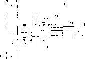
Fig. 1 shows equipment of the present invention with the block diagram form;
Fig. 2 is the specific embodiments of treatment circuit in the equipment shown in Figure 1;
Fig. 3 is the specific embodiments of circuit interface shown in Figure 2;
Fig. 4 a to 4c is the signal waveform at the diverse location place of interface in Fig. 3;
Fig. 5 is the specific embodiments of equipment relay shown in Figure 1;
Fig. 6 and 7 is that two of magnetic compensation circuit of relay shown in Figure 5 can select embodiment.
The power equipment 1 of monitoring prepayment electric quantity shown in Figure 1 is connected with the phase line P of electric power system with 3 by two splicing ears 2.It also is connected with the center line N of electric power system with 5 by two splicing ears 4.
Voltage U also is added to the input of power circuit 12, and power circuit 12 provides suitable supply power voltage Vcc1 and Vcc2 for equipment 1 on power supply terminal.
In prior art equipment, relay is a bi-stable type.Such relay comprises a coil that only just is powered when on off state changes, described on off state changes and promptly becomes off-state from closure state, and vice versa.This relay power consumption is low.But under the situation of electronic processing unit 9 irregular workings of controlling this relay or relay coil irregular working, relay contact 7 can remain on one of them settling position of two settling position.If the contact can be locked on the make position, this just easier realization swindle.
According to the present invention, relay is the monostable relay with normally opened contact, promptly when the seasonal contact of coil 8 energisings 7 closures, break contact when coil 8 no powers.Like this, under the situation of electronic processing unit 9 or relay coil 8 irregular workings, no matter this irregular working causes by fault, cause by premeditated swindle or other reasons that still contact 7 is owing to wrongly disconnect and keep disconnection to rebulid proper operation until equipment 1.
The coil 8 and the electronic switch of relay is connected in series so that be the voltage terminal power supply.When operate as normal, as long as prepayment electric quantity is non-vanishing, treatment circuit just makes electronic switch connect, and powers to the coil 8 of relay then.
Utilize FREQUENCY CONTROL to improve reliability.As shown in Figure 2, treatment circuit 13 comprises power measurement circuit 16, receives voltage signal U and current signal I.Usually, when having consumed for example every consumption of predetermined electric weight kWh, the power measurement circuit provides count pulse to the central location 17 based on microprocessor.The central location 17 of having stored the prepayment electric quantity of being read by card reader 14 in advance reduces the capacity of this memory according to the count pulse that receives.As long as prepayment electric quantity does not use up, central location 17 just provides frequency more than or equal to predetermined frequency (period T, Fig. 4 binary signal A a) to interface 18.The interface 18 that is connected between central location 17 and the relay coil 8 is frequency-voltage (F/V) conversion interfaces.Like this, as long as launch signal enough frequencies, that constitute the relay closes control signal, just direct voltage is added on the coil 8 of relay.If the frequency from the output signal A of central location 17 is too low, especially under the situation of the continous-stable signal of logic level 0 or 1, then cancellation is added to the voltage on the terminal of relay coil 8.Because no longer to relay coil 8 power supply, so relay is transformed on itself and the break contact 7 corresponding monostable positions.
Like this, even, relay is transformed on the open position owing to the fault of processing unit causes the output signal A of control unit to be locked in logic level 1.
Fig. 3 shows a specific embodiments of interface 18.Interface 18 comprises two power inputs (Vcc2 and ground) that are connected with control input end from central location 17 received signal A with the power supply terminal of power circuit 12.The control input end is by being connected with the base stage of the first transistor T1 of NPN type with current-limiting resistance R1 that the first capacitor C1 and the first diode D1 are connected in series.The second capacitor C2 is connected between the base stage and ground of transistor T 1, the grounded emitter of transistor T 1.The collector electrode of transistor T 1 connects the base stage of the transistor seconds T2 of positive-negative-positive, the grounded collector of transistor seconds T2.Connect polarization resistance R2 between the emitter of the collector electrode of transistor T 1 and transistor T 2.The coil 8 of relay is connected with the output of interface 18, and described output connects the emitter of transistor T 2 on the one hand, connects power supply terminal Vcc2 on the other hand.
Describe the operation of interface 8 below with reference to Fig. 4 a, 4b and 4c, Fig. 4 a, 4b and 4c represent voltage signal B on the terminal of signal A, capacitor C2 and the waveform of the voltage signal C on transistor T 2 emitters respectively.
When operate as normal, the electricity consumption advnace money on a contract does not use up, and the 17 generation cycles of central location are the binary signal A of T.By resistor R 1, capacitor C1 and diode D1, these signals remain on greater than preset threshold value S, greater than a value of transistor T 1 base/emitter the charging voltage B on the capacitor C2 terminal.Therefore, transistor T 1 conducting causes transistor T 2 conductings.So, the emitter voltage C of transistor T 2 is near zero, Fig. 4 c, and will be added to continuously near the voltage of supply power voltage Vcc2 on the terminal of relay coil 8 of holding contact 7 closures.
When prepayment electric quantity used up, the signal A that exports from central location 17 was converted to logic level 0.Capacitor C1 does not launch continuous signal, and the charging of capacitor C2 is interrupted.Capacitor C2 then slowly discharges by the base/emitter knot of transistor T 1.Notice that in Fig. 4 b, the charging of capacitor and discharge amplitude have been amplified greatly.In fact, more than threshold value S, voltage B only shakes on every side very slightly at the voltage that charges normal of capacitor C2.In case voltage B drops to below the threshold value S, transistor T 1 just ends, and time t1 also causes transistor T 2 to end, and voltage C is converted to power source voltage Vcc 2.Voltage on the terminal of relay coil 8 is cancelled, and it is open position that contact 7 is transformed into its stable position.When transistor T 2 ended, the one-way transmission diode D2 that is connected with the terminal of coil 8 allowed electric current flow through in transient phase usually.
Be connected and the common point of capacitor C1 and diode D1 between diode D3 be used to the negative signal of pruning.
If all be locked in logic level 1 from the signal A of central location 17 outputs, then the operation of interface is identical, and capacitor C1 stops emission there.Any fault of element or interface all can be interrupted generation and the emission of the signal A of appropriate frequency in the treatment circuit, causes the contact 7 of relay to be converted to safe open position.
For contact 7, utilize a pair of coarse contact material can further improve the operational reliability of equipment.In most preferred embodiment, with silver-and graphite-Ji alloy form one of them static contact element 19a, make another movable contact element 19b with silver-plated copper.
For the preset current level is reduced in the danger of contact welding as much as possible, be provided with a magnetic compensation circuit 20, Fig. 5, this circuit are used for increasing static and movable contact element 19a, the pressure that produces between the 19b under the situation of big electric current especially fault current.Magnetic compensation circuit 20 is around movable contact element 19b.It comprises the element of being made by magnetic material, and this element is preferably the U type, shown in Fig. 6 and 7.This U-type element can be finished by the blade 21 that magnetic material is made, and 19b is fixed together with movable contact element, makes it possible to bear the relay short circuit current of increase.As shown in Figure 7, between the U-type element of blade 21 and magnetic compensation circuit 20, there is predetermined air gap.
Use the magnetic compensation circuit both to reduce the danger of short-circuit conditions lower contact welding, the relay of the coil of being calibrated separately when it is worked with running current 8 is used.Different with the bi-stable type relay, because the continuous power consumption of monostable relay, so this specific character of back is more favourable.
Combination with monostable relay, FREQUENCY CONTROL, a pair of coarse contact material and a magnetic compensation circuit can guarantee to obtain the best degree of reliability higher than known device.
Claims (7)
1. the power equipment of a monitoring prepayment electric quantity (1), comprise: electronic processing unit (9), lead (N with electric power system, P) be connected, calculate power consumption and be scheduled to prepaid value in respect relay (7 in season when power consumption reaches, 8) contact (7) disconnects, described equipment is characterised in that, relay is the monostable type relay with normally opened contact (7), processing unit comprises the power measurement circuit (16) that receives voltage signal (U) and current signal (I) and produces the central location (17) of frequency more than or equal to the binary signal (A) of predetermined frequency, described binary signal makes relay closes, described power measurement circuit (16) provides count pulse to described central location (17) when having consumed predetermined electric weight, connects frequency-voltage transitions interface (18) between CPU (17) and relay.
2. equipment according to claim 1 is characterized in that, interface (18) comprise and power supply terminal between the electronic switch that is connected in series of relay (T1, T2).
3. equipment according to claim 2, it is characterized in that, interface (18) comprises first capacitor (C1) and second capacitor (C2), described first capacitor is connected the control input end and the electronic switch (T1 of interface, T2) between the control electrode, second capacitor is connected between described control electrode and one of them power supply terminal, surpasses the seasonal electronic switch of preset value (S) (T1, T2) conducting with the voltage (B) on convenient second capacitor (C2) terminal.
4. according to each described equipment in the claim 1 to 3, it is characterized in that contact (7) comprise by silver-and first contact element (19a) that constitutes of graphite-Ji alloy and second contact element of being made by silver-plated copper (19b).
5. according to each described equipment in the claim 1 to 3, it is characterized in that it comprises magnetic compensation circuit (20), be used for when big electric current flows through the contact, increasing static and movable contact element (19a, 19b) pressure between of contact (7).
6. equipment according to claim 5 is characterized in that, magnetic compensation circuit (20) comprises around U-type element movable contact element (19b), that magnetic material is made.
7. equipment according to claim 6 is characterized in that, magnetic compensation circuit (20) comprises and movable contact element (19b) blade that fix as one, that magnetic material is made (21).
Applications Claiming Priority (2)
| Application Number | Priority Date | Filing Date | Title |
|---|---|---|---|
| FR9905728A FR2793090B1 (en) | 1999-04-30 | 1999-04-30 | PREPAYMENT ENERGY MONITORING DEVICE HAVING A MONOSTABLE RELAY |
| FR9905728 | 1999-04-30 |
Publications (2)
| Publication Number | Publication Date |
|---|---|
| CN1272678A CN1272678A (en) | 2000-11-08 |
| CN1171266C true CN1171266C (en) | 2004-10-13 |
Family
ID=9545254
Family Applications (1)
| Application Number | Title | Priority Date | Filing Date |
|---|---|---|---|
| CNB001064436A Expired - Fee Related CN1171266C (en) | 1999-04-30 | 2000-04-10 | Power equipment containing monostable state type relay for monitoring prepayment electric quantity |
Country Status (8)
| Country | Link |
|---|---|
| CN (1) | CN1171266C (en) |
| AR (1) | AR023801A1 (en) |
| BR (1) | BR0002148A (en) |
| DZ (1) | DZ3034A1 (en) |
| FR (1) | FR2793090B1 (en) |
| MA (1) | MA25082A1 (en) |
| OA (1) | OA11374A (en) |
| ZA (1) | ZA200001763B (en) |
Families Citing this family (3)
| Publication number | Priority date | Publication date | Assignee | Title |
|---|---|---|---|---|
| EP1448997B1 (en) * | 2001-07-20 | 2006-03-08 | Satyanarayana Manchanahally Venkataramasastry | Energy consumption control unit |
| DE102016217434B4 (en) | 2016-09-13 | 2023-11-16 | Siemens Aktiengesellschaft | Contactor or compact motor feeder with electromagnetic contact load support |
| CN113871253A (en) * | 2021-10-15 | 2021-12-31 | 深圳英飞源技术有限公司 | Relay tensile arc circuit and control method |
Family Cites Families (4)
| Publication number | Priority date | Publication date | Assignee | Title |
|---|---|---|---|---|
| US4240030A (en) * | 1978-12-14 | 1980-12-16 | Bateman Jess R | Intelligent electric utility meter |
| FR2582171A1 (en) * | 1985-05-15 | 1986-11-21 | Brunet Simone | Monostable trigger of electromechanical type |
| US4838404A (en) * | 1986-11-28 | 1989-06-13 | West Virginia University | Token operating system for an electronic device |
| CN1199172A (en) * | 1997-05-09 | 1998-11-18 | 戴鹏辉 | Semi-idleness prepaid watthour meter |
-
1999
- 1999-04-30 FR FR9905728A patent/FR2793090B1/en not_active Expired - Fee Related
-
2000
- 2000-03-15 MA MA25930A patent/MA25082A1/en unknown
- 2000-04-07 ZA ZA200001763A patent/ZA200001763B/en unknown
- 2000-04-10 CN CNB001064436A patent/CN1171266C/en not_active Expired - Fee Related
- 2000-04-18 DZ DZ000070A patent/DZ3034A1/en active
- 2000-04-27 OA OA1200000124A patent/OA11374A/en unknown
- 2000-04-28 BR BR0002148-2A patent/BR0002148A/en not_active IP Right Cessation
- 2000-04-28 AR ARP000102054 patent/AR023801A1/en active IP Right Grant
Also Published As
| Publication number | Publication date |
|---|---|
| DZ3034A1 (en) | 2004-03-27 |
| CN1272678A (en) | 2000-11-08 |
| FR2793090A1 (en) | 2000-11-03 |
| AR023801A1 (en) | 2002-09-04 |
| ZA200001763B (en) | 2000-10-30 |
| BR0002148A (en) | 2001-03-13 |
| FR2793090B1 (en) | 2001-07-13 |
| MA25082A1 (en) | 2000-10-01 |
| OA11374A (en) | 2004-01-27 |
Similar Documents
| Publication | Publication Date | Title |
|---|---|---|
| CN209119805U (en) | Surge protection device | |
| CN1171266C (en) | Power equipment containing monostable state type relay for monitoring prepayment electric quantity | |
| CN212258410U (en) | Anti-impact current protection circuit applied to photovoltaic energy storage system | |
| CN221227170U (en) | Charging circuit and charging pile | |
| CN208675582U (en) | A kind of Novel blood pressure-reducing type LED power circuit | |
| CN219989012U (en) | Intelligent control circuit of electric vehicle circuit breaker | |
| CN219458898U (en) | Impact current-limiting protection circuit | |
| CN2323377Y (en) | Load running controlling device for KWH-meter | |
| CN215911903U (en) | Power supply reverse connection prevention circuit and display screen with same | |
| CN220963143U (en) | Self-adaptive zero-crossing start-stop circuit of relay | |
| CN2387627Y (en) | Deciliter power source of permanent-magnet switching mechanism | |
| CN216749739U (en) | Circuit capable of reducing starting impact current of multiple paths of loads | |
| CN2182458Y (en) | Phase failure switch | |
| CN218583557U (en) | Refrigerator protection circuit | |
| CN2438251Y (en) | Device for avoiding fraudulent use of electricity | |
| CN2129994Y (en) | Micro power consumption phase interruption protector | |
| CN201629577U (en) | Intelligent compensation unit without inrush current | |
| CN212485239U (en) | Signal terminal structure for plug-in circuit breaker | |
| CN2387647Y (en) | Device for preventing fraudulent use of electricity | |
| CN2603981Y (en) | Anti-theft device | |
| CN210273590U (en) | Multi-output emergency power supply FEPS | |
| CN2181084Y (en) | AC and dc electric magnet operation controlling box | |
| CN2379887Y (en) | Hybrid electric relay | |
| CN2350862Y (en) | Arcless AC contactor | |
| CN2305799Y (en) | Protector for interruption of electric appliance |
Legal Events
| Date | Code | Title | Description |
|---|---|---|---|
| C06 | Publication | ||
| PB01 | Publication | ||
| C10 | Entry into substantive examination | ||
| SE01 | Entry into force of request for substantive examination | ||
| C14 | Grant of patent or utility model | ||
| GR01 | Patent grant | ||
| C19 | Lapse of patent right due to non-payment of the annual fee | ||
| CF01 | Termination of patent right due to non-payment of annual fee |