CN1170326C - Current interrupter for electrochemical cells - Google Patents
Current interrupter for electrochemical cells Download PDFInfo
- Publication number
- CN1170326C CN1170326C CNB971943621A CN97194362A CN1170326C CN 1170326 C CN1170326 C CN 1170326C CN B971943621 A CNB971943621 A CN B971943621A CN 97194362 A CN97194362 A CN 97194362A CN 1170326 C CN1170326 C CN 1170326C
- Authority
- CN
- China
- Prior art keywords
- cap assembly
- battery
- assembly according
- pressure
- casing
- Prior art date
- Legal status (The legal status is an assumption and is not a legal conclusion. Google has not performed a legal analysis and makes no representation as to the accuracy of the status listed.)
- Expired - Fee Related
Links
Images

Classifications
-
- H—ELECTRICITY
- H01—ELECTRIC ELEMENTS
- H01H—ELECTRIC SWITCHES; RELAYS; SELECTORS; EMERGENCY PROTECTIVE DEVICES
- H01H37/00—Thermally-actuated switches
- H01H37/02—Details
- H01H37/04—Bases; Housings; Mountings
- H01H37/043—Mountings on controlled apparatus
-
- H—ELECTRICITY
- H01—ELECTRIC ELEMENTS
- H01M—PROCESSES OR MEANS, e.g. BATTERIES, FOR THE DIRECT CONVERSION OF CHEMICAL ENERGY INTO ELECTRICAL ENERGY
- H01M50/00—Constructional details or processes of manufacture of the non-active parts of electrochemical cells other than fuel cells, e.g. hybrid cells
- H01M50/30—Arrangements for facilitating escape of gases
- H01M50/342—Non-re-sealable arrangements
- H01M50/3425—Non-re-sealable arrangements in the form of rupturable membranes or weakened parts, e.g. pierced with the aid of a sharp member
-
- H—ELECTRICITY
- H01—ELECTRIC ELEMENTS
- H01M—PROCESSES OR MEANS, e.g. BATTERIES, FOR THE DIRECT CONVERSION OF CHEMICAL ENERGY INTO ELECTRICAL ENERGY
- H01M50/00—Constructional details or processes of manufacture of the non-active parts of electrochemical cells other than fuel cells, e.g. hybrid cells
- H01M50/50—Current conducting connections for cells or batteries
- H01M50/572—Means for preventing undesired use or discharge
- H01M50/574—Devices or arrangements for the interruption of current
- H01M50/578—Devices or arrangements for the interruption of current in response to pressure
-
- H—ELECTRICITY
- H01—ELECTRIC ELEMENTS
- H01M—PROCESSES OR MEANS, e.g. BATTERIES, FOR THE DIRECT CONVERSION OF CHEMICAL ENERGY INTO ELECTRICAL ENERGY
- H01M50/00—Constructional details or processes of manufacture of the non-active parts of electrochemical cells other than fuel cells, e.g. hybrid cells
- H01M50/50—Current conducting connections for cells or batteries
- H01M50/572—Means for preventing undesired use or discharge
- H01M50/574—Devices or arrangements for the interruption of current
- H01M50/581—Devices or arrangements for the interruption of current in response to temperature
-
- H—ELECTRICITY
- H01—ELECTRIC ELEMENTS
- H01H—ELECTRIC SWITCHES; RELAYS; SELECTORS; EMERGENCY PROTECTIVE DEVICES
- H01H37/00—Thermally-actuated switches
- H01H37/74—Switches in which only the opening movement or only the closing movement of a contact is effected by heating or cooling
- H01H37/76—Contact member actuated by melting of fusible material, actuated due to burning of combustible material or due to explosion of explosive material
- H01H2037/769—Contact member actuated by melting of fusible material, actuated due to burning of combustible material or due to explosion of explosive material characterised by the composition of insulating fusible materials, e.g. for use in the thermal pellets
-
- H—ELECTRICITY
- H01—ELECTRIC ELEMENTS
- H01H—ELECTRIC SWITCHES; RELAYS; SELECTORS; EMERGENCY PROTECTIVE DEVICES
- H01H35/00—Switches operated by change of a physical condition
- H01H35/24—Switches operated by change of fluid pressure, by fluid pressure waves, or by change of fluid flow
- H01H35/34—Switches operated by change of fluid pressure, by fluid pressure waves, or by change of fluid flow actuated by diaphragm
-
- H—ELECTRICITY
- H01—ELECTRIC ELEMENTS
- H01H—ELECTRIC SWITCHES; RELAYS; SELECTORS; EMERGENCY PROTECTIVE DEVICES
- H01H37/00—Thermally-actuated switches
- H01H37/02—Details
- H01H37/32—Thermally-sensitive members
- H01H37/52—Thermally-sensitive members actuated due to deflection of bimetallic element
- H01H37/54—Thermally-sensitive members actuated due to deflection of bimetallic element wherein the bimetallic element is inherently snap acting
-
- H—ELECTRICITY
- H01—ELECTRIC ELEMENTS
- H01H—ELECTRIC SWITCHES; RELAYS; SELECTORS; EMERGENCY PROTECTIVE DEVICES
- H01H37/00—Thermally-actuated switches
- H01H37/74—Switches in which only the opening movement or only the closing movement of a contact is effected by heating or cooling
- H01H37/76—Contact member actuated by melting of fusible material, actuated due to burning of combustible material or due to explosion of explosive material
- H01H37/764—Contact member actuated by melting of fusible material, actuated due to burning of combustible material or due to explosion of explosive material in which contacts are held closed by a thermal pellet
-
- H—ELECTRICITY
- H01—ELECTRIC ELEMENTS
- H01M—PROCESSES OR MEANS, e.g. BATTERIES, FOR THE DIRECT CONVERSION OF CHEMICAL ENERGY INTO ELECTRICAL ENERGY
- H01M50/00—Constructional details or processes of manufacture of the non-active parts of electrochemical cells other than fuel cells, e.g. hybrid cells
- H01M50/50—Current conducting connections for cells or batteries
- H01M50/572—Means for preventing undesired use or discharge
- H01M50/574—Devices or arrangements for the interruption of current
-
- H—ELECTRICITY
- H01—ELECTRIC ELEMENTS
- H01M—PROCESSES OR MEANS, e.g. BATTERIES, FOR THE DIRECT CONVERSION OF CHEMICAL ENERGY INTO ELECTRICAL ENERGY
- H01M50/00—Constructional details or processes of manufacture of the non-active parts of electrochemical cells other than fuel cells, e.g. hybrid cells
- H01M50/50—Current conducting connections for cells or batteries
- H01M50/572—Means for preventing undesired use or discharge
- H01M50/584—Means for preventing undesired use or discharge for preventing incorrect connections inside or outside the batteries
- H01M50/586—Means for preventing undesired use or discharge for preventing incorrect connections inside or outside the batteries inside the batteries, e.g. incorrect connections of electrodes
-
- Y—GENERAL TAGGING OF NEW TECHNOLOGICAL DEVELOPMENTS; GENERAL TAGGING OF CROSS-SECTIONAL TECHNOLOGIES SPANNING OVER SEVERAL SECTIONS OF THE IPC; TECHNICAL SUBJECTS COVERED BY FORMER USPC CROSS-REFERENCE ART COLLECTIONS [XRACs] AND DIGESTS
- Y02—TECHNOLOGIES OR APPLICATIONS FOR MITIGATION OR ADAPTATION AGAINST CLIMATE CHANGE
- Y02E—REDUCTION OF GREENHOUSE GAS [GHG] EMISSIONS, RELATED TO ENERGY GENERATION, TRANSMISSION OR DISTRIBUTION
- Y02E60/00—Enabling technologies; Technologies with a potential or indirect contribution to GHG emissions mitigation
- Y02E60/10—Energy storage using batteries
Landscapes
- Chemical & Material Sciences (AREA)
- Chemical Kinetics & Catalysis (AREA)
- Electrochemistry (AREA)
- General Chemical & Material Sciences (AREA)
- Gas Exhaust Devices For Batteries (AREA)
- Connection Of Batteries Or Terminals (AREA)
- Primary Cells (AREA)
- Hybrid Cells (AREA)
- Closures For Containers (AREA)
Abstract
A current interrupt mechanism for electrochemical cells is disclosed. A thermally activated current interrupt mechanism (38) is integrated into an end cap assembly (10) for an electrochemical cell. The thermally responsive mechanism preferably includes a free floating bimetallic disk (40) or a meltable mass of material (fig. 4, 175) to break an electrical pathway within the end cap assembly. The end cap assembly may also include integrated therein a pressure responsive current interrupt mechanism (48). The pressure responsive mechanism activates to sever an electrical pathway within the end cap assembly (10) to prevent current from passing through the cell, and includes a diaphragm (70) which ruptures when there is extreme gas pressure buildup.
Description
Technical field
The present invention relates to a kind of thermal response cutout that is used for electrochemical cell, when the temperature of battery too raise, this cutout prevented the electric current battery of flowing through reliably.The invention still further relates to a kind of pressure-responsive cutout, when setting up excessive gas pressure in the battery, this cutout cuts off battery reliably.
Background technology
Electrochemical cell, particularly high energy density cells are those batteries of active material as lithium, easily take place to leak and break, and this can cause again to battery powered device or to the infringement of surrounding environment.Under the situation of rechargeable battery, cause the rising of internal temperature of battery by overcharging electric energy.Undesirable temperature raises and often is attended by the corresponding increase of internal gas pressure.This may take place under the situation of contingency external short circuit.Wish safety device to be accompanied by battery and excessively do not increase battery cost, size or quality.
This battery is particularly used the rechargeable battery of lithium as active material, and being raise by the internal temperature of battery that often is attended by the corresponding increase of pressure easily causes and leak and break.This may by as the abuse conditions or the short circuit condition of overcharging and so on cause.It is also very important to seal these batteries airtightly, to prevent overflowing and invading from the moisture of external environment condition of electrolyte solvent.
As mentioned above, when a kind of battery charge like this, take place from heating.The fast speed of ether is charged or is overcharged the increase that electric energy causes temperature.When temperature surpasses a fixed point (this chemical property and structure with battery becomes), begin undesirable and uncontrollable heat dissipation state.In addition, owing to cross heating, set up internal pressure, and electrolyte can spray suddenly from battery.Be preferably in this controlled ventilation takes place to begin before.
The conventional batteries structure adopts a kind of end cap part, after galvanic anode and active material of cathode and suitable isolated material and electrolyte have been inserted in the cylindrical housings, this end cap part is inserted in the open-ended cylindrical housings.End cap contacts with one of male or female material is electric, and the exposed portions serve of end cap forms one of battery terminal.The part of battery container forms another terminal.Prior art discloses the device of response excess pressure state, and these devices are incorporated in the end cap part.
The present invention has one or several current breaking mechanism of incorporating in the single-ended cap assemblies, and this single-ended cap assemblies can be advantageously used in once or secondary (chargeable) battery, for example, and by end-cap assembly being inserted into the shell nozzle end that is used for battery.End-cap assembly of the present invention is for rechargeable battery, for example lithium ion, nickel metal hydride, NI-G or other rechargeable batteries, has special purposes, with during being exposed to high temperature, undue or inappropriate charging or battery short circuit, overcome the danger that pressure is set up in battery overcharge and the battery.
Summary of the invention
On the one hand, the present invention is intended to a kind of end-cap assembly that is used for electrochemical cell, this battery has positive and negative terminal and pair of internal electrodes (anode and negative electrode), described end-cap assembly comprises a housing and an end casing that exposes, described plate plays a battery terminal, described end-cap assembly has the conductive path that passes wherein, when described end-cap assembly is used for battery, allow end casing to be connected electrically on the battery electrode, described end-cap assembly further comprises: a) be used for preventing the flow through thermal response device of described electric path of electric current, the temperature of wherein said thermal response device in described end-cap assembly is activatable when reaching a predetermined value, described electric path is disconnected, b) pressure-responsive device, this pressure-responsive device comprises that but is positioned at the described end-cap assembly end place broken piece of described end casing vis-a-vis, but described broken piece is broken when the gas pressure on the described end casing farthest side reaches the predetermined value that generation is broken in described at it, allows gas therefrom to pass.
Description of drawings
To understand feature of the present invention better with reference to accompanying drawing, in the accompanying drawings:
Fig. 1,2 and 3 is the longitudinal sectional views that obtain through the line of observation 1-1 of the end-cap assembly of Fig. 6.
Fig. 1 is illustrated in thermal actuation current breaking mechanism and the pressure actuated current breaking mechanism in the circuit connection mode.
Fig. 2 is illustrated in the thermal actuation current breaking mechanism in the pattern that opens circuit.
Fig. 3 is illustrated in the pressure actuated current breaking mechanism in the pressure actuated pattern that opens circuit.
Fig. 4 is the longitudinal sectional view of a kind of another embodiment of end-cap assembly, and this end-cap assembly has pressure actuated current breaking mechanism and the thermal actuation current breaking mechanism that is incorporated in wherein, and one of them thermosensitive part softens to unclamp an elastic component open circuit.
Fig. 5 is the exploded perspective view of the element of the end-cap assembly of the present invention shown in Fig. 1 embodiment.
Fig. 6 is the stereogram of end-cap assembly bottom, expression pressure-resistant plate and perforation air vent hole wherein.
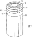
Fig. 7 is a stereogram, and expression is inserted in the end-cap assembly of the present invention in the battery cylindrical shape shell nozzle end.
Fig. 8 is a stereogram, and expression has the completed cell that is inserted in the end-cap assembly of the present invention in the battery cylindrical shape shell nozzle end, and the end casing of described assembly forms a terminal of battery.
Embodiment
End-cap assembly 10 of the present invention (Fig. 1) can be used for once or secondary (chargeable) battery.In a most preferred embodiment, end-cap assembly 10 can be inserted in the openend 95 (Fig. 7) of a typical cylindrical housings 90 that is used for battery.Battery comprise a positive pole (negative electrode during discharge), a negative pole (anode during discharge), spacer and electrolyte and respectively with the positive and negative outside terminal of both positive and negative polarity electrical communication.
Referring now to Fig. 1 of accompanying drawing,, the end-cap assembly 10 that plan is inserted in the openend of a battery container discharges sub-component 48 but comprising cutout sub-component 38 and a pressure of being incorporated in one of them thermal actuation.Sub-component 38 and 48 is separated by a common support plate 60.Sub-component 38 and 48 remains in the lid 30, and lid 30 limits the outer wall of end-cap assembly 10.Breaker assembly 38 is limited by a disc-shaped cap plate 20 on its top, and is limited to the contact plate 15 on the supporting bracket 60 by a block welding in its bottom.Disc-shaped cap plate 20 forms one of outside terminal of battery.Supporting bracket 60 separates chamber in the heater assembly 38 68 and the chamber 78 that pressure discharges in the sub-component 48.Contact plate 15 is connected electrically on the supporting bracket 60, and when end-cap assembly 10 was used for a battery, supporting bracket 60 was connected electrically to again on the electrode 88 (male or female) of battery.Provide a thermal response breaker mechanism (40,50), to finish the circuit between contact plate 15 and the end cap 20.If the temperature in the battery surpasses a predetermined threshold, then breaker mechanism activates and disconnects electric contact the between end cap 20 and the contact plate 15, prevents the electric current battery of flowing through thus.
Pressure discharges sub-component 48 and comprises a thin metal diaphragm 70 that is connected on the pressure-resistant plate 80, and the conductive tabs 87 of pressure-resistant plate 80 through being welded on the plate 80 is connected on the battery electrode 88.Pressure-resistant plate conducts electricity, and has enough thickness, thereby it is at least up to about 600psi (4.14 * 10
6Pascal) indeformable basically under the rising pressure.If when the gas pressure in the battery raise to such an extent that surpass a predetermined threshold, then barrier film 70 outwards protruded, contact with the electric of pressure-resistant plate 80 to disconnect, prevent current direction battery or therefrom outflow thus.Pressure-resistant plate 80 and supporting bracket 60 preferably also have eyelet 73 and 63 respectively, and its perforations 73 and 63 helps to discharge gas and discharges the pressure that is based upon in the battery.
In the most preferred embodiment shown in Fig. 1, in rechargeable battery, for example in the lithium ion chargeable battery, can use side cap assemblies 10.Lithium ion chargeable battery is characterised in that lithium ion is delivered to positive pole from negative pole when battery discharge, and is delivered to negative pole from positive pole when battery charge.It generally can have a lithium and cobalt oxides (Li
xCoO
2) or the lithium manganese oxide (Li of spinel crystal structure
xMn
2O
4) positive pole and a carbon negative pole.Negative pole constitutes the galvanic anode of interdischarge interval and the negative electrode between charge period, and the cell cathode of anodal formation interdischarge interval and the anode between charge period.The electrolyte that is used for this battery can comprise the lithium salts that is dissolved in the anhydrous solvent mixture.Salt can be LiPF
6, and solvent can advantageously comprise dimethyl carbonate (DMC), ethylene carbonate (EC), propylene carbonate (PC) and its mixture.And the present invention can be used for other rechargeable battery, for example nickel metal hydride battery and nickel-cadmium cell.End-cap assembly 10 comprises that one generally is the end cap terminal 20 of the plus end of rechargeable battery, a metal profile 60 and the insulating disc 35 between end cap 20 and supporting bracket 60 that forms the supporting substrate of cover plate 20 belows.The pressure that cap assemblies 10 also advantageously is equipped with below supporting bracket 60 discharges barrier film 70, as shown in fig. 1.Barrier film 70 can be soldered to one and supports on the pressure-resistant plate 80.This can advantageously realize by the substrate of barrier film 70 being welded on the rise part 82 that supports pressure-resistant plate 80.The material of barrier film 70 should conduct electricity, and the pressure of foundation plan actuation diaphragm, and the minimum thickness of barrier film 70 should be between about 0.1 and 0.5 millimeter.Can wish that barrier film 70 is an aluminium.Advantageously barrier film 70 is suppressed decorative patterns, thereby it breaks under predetermined pressure.That is, membrane surface can be suppressed or etching, thereby the part on surface has the thickness littler than remainder.One that uses in the present invention best barrier film 70 compacting decorative patterns, so that semicircle or " C " shape groove 70a are added in its surface.The shape of groove advantageously is same as or is similar to the shape of barrier film 70 periphery major parts, and advantageously is positioned near the periphery.The concrete pressure that ventilation takes place can be controlled such as the degree of depth, position or the shape of groove and the parameter the material hardness by changing.When hypertonia, barrier film will break along the line of rabbet joint.End cap 20 and supporting bracket 60 limit a chamber 68 of wherein settling a thermal actuation cutout sub-component 38 between it.Insulating disc 35 forms by a peripheral foot part 35a with from the downward-sloping arm portion 35b of its extension.Arm 35b extends in the chamber 68.Barrier film 70 is designed to break when gas in accumulating in battery reaches a predetermined threshold.Zone gas that accumulates in when barrier film 70 breaks in the battery of formation between supporting bracket 60 and the barrier film 70 can be arranged chamber 78 into.
Interrupter assembly 38 comprises a thermal response bi-metal plate 40, one and a resilient spring like part 50 electric metallic contact plates that contact 15.As shown in Fig. 1 and 5, elastic component 50 can be formed by a single flexible piece, this list flexible piece has an outer circular peripheral part 50a, a disk holder contact pin part 50c extends radially inwardly from peripheral part 50a, so that during any orientation of battery, generally bi-metal plate 40 is freely kept putting in place, and do not limit its snap action motion.This part externally some place of part 50a can be welded on the end casing 20, and a center contact portion 50b is contacted with plate 15.In addition, contact portion 50b can be designed to have the cross-sectional area that reduces, thereby it can play a kind of fuse connection of dividing, to avoid the influence of power fluctuation state.Location bi-metal plate 40, so that freely mesh the inclined arm 35b of insulating disc 35, all arms are used from the effect of the dish seat of dish 40.Bi-metal plate 40 preferably also comprises a centre bore that rises contact portion that is used for accepting metallic contact plate 15.Contact plate 15 preferably is welded on the supporting bracket 60, and a surface that is used to settle elastic component 50 is provided, as shown in fig. 1.An electric insulation packing ring 25 that extends above the periphery of end cap 20 and along the bottom peripheral edge of barrier film 70 is arranged.Packing ring 25 is also in abutting connection with the outward flange of sub-component 38, as shown in fig. 1.Can there be one in packing ring 25 top edge upper bead and compress the becket 55 of barrier film 70 with end cover component internal element.Packing ring 25 is used for an end cap 20 and opens with crimping ring 55 electric insulations, and forms the sealing between supporting bracket 60 and the crimping 55.The lid 30 of end-cap assembly 10 can by among Fig. 5 the untapered cylindrical part of clear expression form.In complete battery component (Fig. 8), the outer surface of lid 30 will contact with the inner surface of battery container 90.Supporting bracket 60 provides a substrate for the element of settling assembly 38, and preferably has arc to keep being adjacent to the active radial pressure of packing ring 25 inner surfaces.Supporting bracket 60 has eyelet 63 in the surface within it, when breaking with convenient barrier film 70 gas is discharged to upper chamber 68.The gas that flows into upper chamber 68 is discharged to the main air vent hole 67 in end cap 20 in the external environment condition.End-cap assembly lid 30 contacts with battery container 90, and battery container 90 and relative terminal generally are the electric contacts of negative terminal in the lithium ion chargeable battery housing.Thereby packing ring 25 provides between end cap 20 and the outer wall 30, and promptly the electric insulation between two terminals of battery prevents battery short circuit thus.An other dead ring can be arranged, and promptly at the top of outer wall 30 and the insulated leg ring 42 between the pressure-resistant plate 80, as shown in fig. 1, also guaranteeing does not have short circuit between the positive and negative terminal of battery.
Barrier film 70 is the dish type of aluminium composition preferably, advantageously has the thickness between about 3 and 10 mils.Under such thickness, the internal gas pressure in battery is raised at least at about 100psi and 200psi (6.894 * 10
5With 13.89 * 10
5During threshold value Pascal), the welding between barrier film substrate 72 and the supporting bracket 80 disconnects, and barrier film substrate 72 projectioies and separate (Fig. 3) with supporting bracket 80.If (for example battery is to be higher than the voltage charging of recommendation, if perhaps battery short circuit or misuse, then this pressure raises and may take place.Yet), if desired, can be adjusted to the thickness of barrier film substrate 72 easily at other force value lower convexity.Barrier film substrate 72 disconnects all electric contacts between barrier film 70 and the plate 80 with the separation of supporting bracket 80.This separation also disconnect end cap 20 and with battery electrode 88 that plate 80 contacts between electric path, thereby electric current no longer flows to battery or therefrom flows out, and battery is opened circuit.Even after current path disconnects, if because other reasons for example heats in stove, and the pressure in the battery continues to rise, then venting membrane 70 preferably also will be at least about 250psi and 400psi (17.2 * 10
5With 27.6 * 10
5Pascal) breaks in case battery explosion under the threshold pressure between.Under such extreme case, breaking of venting membrane 70 allows gas to discharge from the air vent hole 73 (Fig. 1 and 6) of inside battery through pressure-resistant plate 80, and gas enters (Fig. 1) in the lower chamber 78 subsequently.Gas then from lower chamber 78 through supporting bracket 60 air vent hole 63 (Fig. 1) and if necessary the air vent hole (not shown) in insulating disc 35 flow to upper chamber 68.The gas that accumulates in the upper chamber 68 is discharged to the main air vent hole 67 in end casing 20 in the external environment condition.
Cutout feature of the present invention can be described with reference to Fig. 1-3.In the specific embodiment shown in should be noted that therein, when end-cap assembly 10 was used for battery, one of battery electrode contacted with plate 80 through contact pin 87.During normal battery operated, plate 80 is electrically connected with end casing 20 again.In lithium ion battery, with plate 80 electrodes in contact 88 can be anodal easily.This electrode will insulate with battery container 90.The negative pole (not shown) will be connected on the battery container 90.The embodiment of Fig. 1 is illustrated in by activating thermocutout bi-metal plate 40 or actuation pressure and discharges barrier film 70 and turn-off current end-cap assembly profile before.In specific embodiment shown in Figure 1, plate 80 and barrier film 70 electric contacts, and barrier film 70 and supporting bracket 60 electric contacts.Supporting bracket 60 and contact plate 15 electric contacts, contact plate 15 and elastic component 50 electric contacts, elastic component 50 again with end cap 20 electric contacts.In entire terminal cover structure of the present invention shown in Figure 1, can disconnect in two ways with electric contact the between the end cap 20 with pressure-resistant plate 80 electrodes in contact 88.As mentioned above, if pressure is elevated to a predetermined threshold in battery, when then leaving pressure-resistant plate 80, disconnect contacting between barrier film 70 and the pressure-resistant plate 80 when barrier film substrate 72 projection.This disconnection in the circuit prevents the current direction battery or therefrom flows out.In addition, if battery is overheated, then the bi-metal plate 40 of thermal cut-out sub-component 38 activates, and upwards promotes from insulator 35b at the same time, and elastic component 50 is thrown off from contact plate 15.This in fact cuts off the electric path between electrode contact 87 and the end cap 20, thereby prevents current direction battery or therefrom outflow.The invention has the advantages that these two disconnecting mechanisms are combined in the single-end cap assemblies 10, and end-cap assembly 10 can be used as the openend that individual unit is inserted in battery container.
Bi-metal plate 40 had better not physically be fixed on the support insulating 35, but freedom of motion, promptly it is placed on the dish 35b, as shown in fig. 1 with free suspended state.In this structure, no matter battery is charging or discharge, the electric current bi-metal plate 40 of flowing through at no time.This be because the dish 40 when not activating not with contact plate 15 electric contacts.Yet, surpass a predetermined threshold if battery is overheated, bi-metal plate 40 is carried out suitable calibration, so that its jerk or distortion (Fig. 2) make its promote elastic component 50 and leave contact plate 15, prevent that thus electric current from flowing between battery terminal.Bi-metal plate 40 is so calibrated, thereby it has predetermined dish, and when reaching given threshold temperature, the permission dish activates.The free suspension structure of the bi-metal plate 40 on above-mentioned insulating disc arm 35b allows electric current therefrom flow through at no time, and no matter battery is charging or discharge.This is easier to the calibration of metal dish 40 and is more accurate, because the heating effect (I that is caused by the electric current of the bi-metal plate 40 of flowing through not
2The R heating).Bi-metal plate 40 can be made up of two-layer different metal with different heat expansion coefficient easily.The top layer of bi-metal plate 40 (layer of the most close end cap 20) can be made up of the big metal of thermal expansion, nichrome preferably, and supporting layer or bottom can be made up of the little metal of thermal expansion, preferably dilval.In this embodiment, dish 40 can activate when temperature is elevated at least about 60 to 75 ℃, makes dish 40 be out of shape to such an extent that be enough to promote contacting of elastic component 50 disengagements and contact plate 15.Also might select the big and little metal level of thermal expansion, thereby under being lower than-20 ℃ temperature, dish 40 does not reset, these are in most of purposes, and making this device is the hot staticizer of a kind of single-acting.
The optimal material that is used for said elements is described below: end cap 20 preferably is made up of stainless steel or nickel-plated steel, and thickness is between about 8 to 15 mils (0.2 and 0.375mm), so that suitable support, intensity and resistance to corrosion to be provided.The outer wall 30 of end-cap assembly 10 also preferably is made up of stainless steel or nickel-plated steel, has the thickness between about 8 and 15 mils (0.2 and 0.375mm).Pressure-resistant plate 80 is aluminium preferably, has the thickness between about 10 and 20 mils (0.25 and 0.5mm), can be reduced in the center at the thickness point place that contacts with barrier film substrate 72, between about 2 and 5 mils (0.05 and 0.125mm).Insulated leg ring 42 can be made up of a kind of high-temperature thermoplastics, as available from General Electric's Plastics Company (General Electric Plastics Company) under trade mark VALOX, as to consider intensity and durability high-temperature polyester.Crimping ring 55 preferably is made up of stainless steel or nickel-plated steel, considers that intensity and resistance to corrosion have the thickness between about 8 and 15 mils (0.2 and 0.375mm).Barrier film 70 is aluminium preferably, has the thickness between about 3 and 10 mils (0.075 and 0.25mm).Under such thickness, when internal gas pressure surpasses at about 100psi and 250psi (6.89 * 10
5With 17.2 * 10
5During threshold pressure Pascal), barrier film will disconnect from its weld seam to pressure-resistant plate 80.If internal gas pressure surpasses at about 250psi and 400psi (17.2 * 10
5With 27.6 * 10
5Pascal) threshold pressure between, then barrier film 70 will break, with the other release of gas pressure that foundation is provided.Settle the insulating disc 35 of bi-metal plate 40 preferably to form on it by the material of high compression-strength, high thermal stability and low die shrinkage.Being used to coil 35 suitable material is liquid crystal polymer or similar material, and thickness can obtain from Celanese Co. under trade mark VECTRA between 10 and 30 mils (0.25 and 0.75mm).Supporting bracket 60 preferably is made up of stainless steel or nickel-plated steel, and so that suitable intensity and resistance to corrosion to be provided, thickness is between about 10 and 30 mils (0.25 and 0.75mm).Elastic component 50 is advantageously formed by beryllium copper, monel, stainless steel or similar material, has good spring action and good conductivity.The suitable thickness of elastic component 50 when being formed by beryllium copper or monel is between about 3 and 8 mils (0.075 and 0.2mm), to provide enough intensity and current capacity.This material can be coated with or stud with silver or gold at contact area, so that lower resistance to be provided in this zone.Contact plate 15 advantageously by be coated with such as gold or silver-colored the cold-rolled steel sheet of precious metal forms, to reduce contact resistance and raising reliability.It also can be formed by ambrose alloy clad alloy, stainless steel or nickel-plated steel.Packing ring 25 is generally made by the polymeric material such as nylon or polypropylene.Sealing around the end-cap assembly element should be airtight, also has the electrolyte of gas form to enter end cap cavity or leaves battery so that prevent existing liquid form.
After end-cap assembly 10 is finished, can be inserted in the openend 95 of a cylindrical battery housing 90, as shown in Figure 7.Battery container 90 is welded at the periphery of its openend on the outer wall of lid 30 of end-cap assembly 10, to provide airtight tight seal between end-cap assembly 10 and battery container 90.The perimeter wall of crimping ring 55 is close to the airtight tight seal of the radial pressure generation of packing ring 25 and barrier film 70 around the inner member of end-cap assembly 10.
Have another embodiment of the end cover structure of the pressure release mechanism that is integrated in wherein and thermal actuation current breaking mechanism, be expressed as the end-cap assembly 110 among Fig. 4.Except not adopting bi-metal plate actuation spring shape mechanism, the embodiment of Fig. 4 is similar to relative Fig. 1-3 at embodiment described above.Replacing provides a hot disk 175, to keep a resilient spring like part 150 and contact plate 115 electric contacts.Contact plate 115 again with end casing 20 electric contacts.Elastic component 150 can comprise a long and thin metal arm 150a who at one end is welded on the supporting bracket 60.Supporting bracket 60 and barrier film 70 electric contacts.Barrier film 70 is welded to again on the rise part 82 that supports pressure-resistant plate 80.Electrode contact 87 and plate 80 electric contacts.Elastic component 150 is preferably in its other end with dish type or convex part 150b termination, and convex part 150b contacts with contact plate 115.An electric insulation dish 120 is arranged, to prevent direct contact the between supporting bracket 60 and the contact plate 115 above the periphery 60a of supporting bracket 60.Thereby, compress as long as keep elastic component 150 pasting contact plate 115, between supporting bracket 60 and end cap 20, electric the contact just arranged.Supporting bracket 60 again with aluminium barrier film 70 electric contacts, barrier film 70 contacts with plate 80, and when end-cap assembly 110 is used for battery, contacts with a battery electrode 88 through contact pin 87.(end-cap assembly 110 can be inserted into it the openend of a cylindrical housings 90 and be used for battery by with embodiment illustrated in fig. 1 in same way as described above with reference.) therefore, when elastic component 150 is kept pasting contact plate 115 and compressed by hot disk 175, between a battery electrode 88 (through contact pin 87) and end cap 20, electric the contact just arranged, and permission is battery operated normally.Surpass a predetermined threshold if battery is overheated, the support that is used for elastic component 150 is removed in then disk 175 fusings thus.The fusing of disk 175 makes elastic component 150 downward jerks, and disconnection contacts with the electric of contact plate 115.The electric path that this in fact cuts off between electrode contact 87 and the end cap 20 prevents current direction battery or therefrom outflow thus.If the gas pressure in the battery surpasses a predetermined value, then barrier film 70 will break, and cut off electric contact the between plate 80 and the barrier film 70 thus, and permission gas respectively the air vent hole in supporting bracket 60 and end cap 20 63 and 67 escape in the external environment condition.
The optimal material that is used for the end cap of mentioning 20 embodiment illustrated in fig. 4, supporting bracket 60, contact plate 115 and aluminium barrier film 70 can be with described identical to the respective element with same numeral shown in Fig. 1-3.Contact plate 115 is preferably by stainless steel or be coated with silver or the nickel-plated cold-rolled of gold is formed, to reduce its contact resistance.Insulating disc 120 shown in Fig. 4 is preferably made by the high-temperature thermoplastics with excellent electrical properties.Be used to coil 120 optimal material and can be at polyimides that obtains from E.I.DuPont Co. under the trade mark KAPTON or the high-temperature polyester that under trade mark VALOX, obtains from General ElectricPlastics Co..Elastic component 150 can be advantageously formed by the beallon of thickness between about 5 and 10 mils (0.125 and 0.25mm), and good electrical conductivity is provided when contacting with plate 115 with box lunch, and provides reliable spring action when disk 175 is adjacent to its pressure when removing.In addition, elastic arm 150 can be coated with silver or gold, to improve its conductivity.Hot disk 175 is advantageously formed by a kind of polymer, and this polymer has than low melting point, for example between about 65 ℃ and 100 ℃, but has good compression strength, during normal battery operated elastic arm 150 maintenances are put in place.The suitable material that is used to have the hot disk 175 of such performance is the Tissuemat E that obtains from Petrolyte Co. under trade mark POLYWAX.Melt in the desired temperature scope of the hot disk 175 of this Tissuemat E between about 75 ℃ and 80 ℃.
The decomposition view of end-cap assembly 10 is illustrated among Fig. 5 among Fig. 1.End-cap assembly 10 can be made by the element shown in the installation diagram 5 in the following order: form a pre-assembled component, comprise element 20,50,40,35,15,60,70,25 and 55.This finishes as follows easily: at first plastic washer 25 is inserted in the crimping ring 55, then venting membrane 70 is inserted in the packing ring 25, and subsequently supporting bracket 60 and the contact plate 15 that is welded on it are inserted in the venting membrane 70.Subsequently insulating disc 35 is placed on around the contact plate 15, and places bi-metal plate 40 with on the oblique arm 35b that dips down that is placed in insulating disc 35.Bi-metal plate 40 is not bonded on the insulating disc 35, but settles thereon with free suspended state, makes insulating disc help to be used from the effect of the positioner of bi-metal plate.The upper surface of resilient spring like part 50 outer ends is welded on the periphery of end cap 20.Then end cap 20 and the elastic component 50 that is welded on it are placed insulating disc 35 tops, thus rise core contact resilient spare 50 inside end of contact plate 15, and the periphery of the bottom surface of elastic component 50 outer ends contact insulating disc 35.Thereby the outer end of elastic component 50 is wedged between end cap 20 and the insulating disc 35, and the other end of elastic component 50 or the inner contact with contact plate 15.Then, ring 55 crimping mechanically above the top edge of packing ring 25, the periphery that is closely pasting end cap 20 with the upper end that keeps packing ring 25 compresses.This crimping applies mechanical force by center of gravity (indulging) axle along ring 55 and finishes.Then in the second crimping step, radially apply mechanical pressure to the wall of crimping ring 55, finish the assembling of pre-assembled component thus.Radially crimping is used for keeping the inner member of pre-assembled component closely and airtightly to be sealed in the ring 55.Then pre-assembled component is inserted in the crown cap 30, thereby the bottom surface of crimping ring 55 is being pasted and is covered 30 bottom inward flange and settle.The bottom surface of crimping ring 55 is welded to and covers on 30 the bottom interior surface subsequently.Then pressure-resistant plate 80 is withheld the bottom of insulated leg ring 42, and insulated leg ring 42 and the pressure-resistant plate 80 that is connected thereto pasted cover 30 outside bottom surface and place, thereby the rise core of pressure-resistant plate 80 contacts venting membrane 70.This contact point between spot welding pressure-resistant plate 80 and the barrier film 70 is finished the construction of end-cap assembly 10 thus then.End-cap assembly 10 can be used for battery, for example, in the openend of the cylindrical housings 90 by it being inserted into battery shown in Figure 7, and at openend 95 places of housing 90, the outer surface of lid 30 is welded on the inner surface of cylindrical housings 90.This generates the battery 100 shown in Fig. 8, and end-cap assembly 10 closely is sealed in the cylindrical housings 90, and end casing 20 forms a terminal of battery.
Although described the present invention, the invention is not restricted to specific embodiment, but limit by claims and its equivalent according to some most preferred embodiments.
Claims (14)
1. end-cap assembly that is used for electrochemical cell, this battery has positive and negative terminal and pair of internal electrodes, described end-cap assembly comprises a housing and an end casing that exposes, described plate plays a battery terminal, described end-cap assembly has the conductive path that passes wherein, when described end-cap assembly is used for battery, allow end casing to be connected electrically on the battery electrode, described end-cap assembly further comprises:
A) be used for preventing the flow through thermal response device of described electric path of electric current, the temperature of wherein said thermal response device in described end-cap assembly is activatable when reaching a predetermined value, and described electric path is disconnected,
B) pressure-responsive device, this pressure-responsive device comprises that but is positioned at the described end-cap assembly end place broken piece of described end casing vis-a-vis, but described broken piece is broken when the gas pressure on the described end casing farthest side reaches the predetermined value that generation is broken in described at it, allows gas therefrom to pass.
2. end-cap assembly according to claim 1, wherein said battery have a cylindrical housings, and end-cap assembly is used for battery by being welded in the openend that it is inserted into cylindrical housings and end-cap assembly on the housing.
3. end-cap assembly according to claim 1, wherein said thermal response device is included in a chamber in the described end-cap assembly, and comprise a bimetal piece and an elastic conduction spare, elastic component forms the part of described electric path, wherein when the battery temperature in the described assembly reaches predetermined value, the bimetal piece distortion pushes described resilient metal member thus, and described electric path is disconnected.
4. end-cap assembly according to claim 3, wherein bimetal piece freely is placed on the surface of an electrical insulation in the described end-cap assembly.
5. end-cap assembly according to claim 4, the part of wherein said resilient metal member is clipped between a described end casing part and the described electrical insulation part, and wherein end-cap assembly comprises a contact plate that forms described electric path part, and wherein said elastic component contacts with described contact plate is electric.
6. end-cap assembly according to claim 1, but comprise that further one strides across end-cap assembly inner width and the separator between described end casing and described broken piece, and described separator separates described thermal response device and described pressure-responsive device.
7. end-cap assembly according to claim 6, wherein said separator comprises a metallic plate, this metallic plate has a hole therein at least, thereby but when described broken piece was broken, gas was by described hole and enter in the described chamber of described end-cap assembly.
8. end-cap assembly according to claim 7, wherein said end casing have at least one and run through wherein hole, thereby but when described broken piece was broken, the gas of assembling from described chamber was by described ending cover hole and lead to the external environment condition.
9. end-cap assembly according to claim 6, but wherein said broken piece comprises a rupturable barrier film.
10. end-cap assembly according to claim 5, wherein when described bimetal piece reaches a predetermined temperature, its distortion makes elastic conduction spare cut off being electrically connected of itself and described contact plate, disconnects described electric path thus.
11. end-cap assembly according to claim 9, further comprise an electric insulation packing ring that contacts with the periphery of the periphery of end casing and barrier film, described end-cap assembly further comprises a crimping spare around described packing ring mechanical crimp, to keep described diaphragm plate and described end casing under mechanical pressure.
12. end-cap assembly according to claim 11 further comprises a crown cap around described crimping spare.
13. end-cap assembly according to claim 12, the openend of the cylindrical housings of end-cap assembly by its being inserted battery and the outer surface of described lid is welded on the inner surface of described housing and is used for battery wherein, end-cap assembly closely is sealed in the cylindrical housings subsequently, and the end casing that comprises a terminal of battery is exposed in the external environment condition.
14. end-cap assembly according to claim 1, wherein the thermal response device comprises and the electric elastic conduction spare that contacts of described end casing, with a fusible material piece, keep described elastic conduction spare to be electrically connected between another current-carrying part of described end casing and end-cap assembly, when end-cap assembly is used for battery, described another current-carrying part is suitable for being connected electrically on the battery electrode, during battery operated, provide being electrically connected between described end casing and the described electrode thus, wherein when battery temperature reaches a predetermined value, described material block fusing, make described elastic component motion thus, disconnect being electrically connected between described end casing and the described battery electrode, stop battery operated thus.
Applications Claiming Priority (4)
| Application Number | Priority Date | Filing Date | Title |
|---|---|---|---|
| US1515396P | 1996-04-10 | 1996-04-10 | |
| US60/015,153 | 1996-04-10 | ||
| US08/720,616 | 1996-10-02 | ||
| US08/720,616 US5691073A (en) | 1996-04-10 | 1996-10-02 | Current interrupter for electrochemical cells |
Publications (2)
| Publication Number | Publication Date |
|---|---|
| CN1217823A CN1217823A (en) | 1999-05-26 |
| CN1170326C true CN1170326C (en) | 2004-10-06 |
Family
ID=26687019
Family Applications (1)
| Application Number | Title | Priority Date | Filing Date |
|---|---|---|---|
| CNB971943621A Expired - Fee Related CN1170326C (en) | 1996-04-10 | 1997-04-10 | Current interrupter for electrochemical cells |
Country Status (13)
| Country | Link |
|---|---|
| US (1) | US5691073A (en) |
| EP (1) | EP0907974B1 (en) |
| JP (1) | JP4404230B2 (en) |
| CN (1) | CN1170326C (en) |
| AT (1) | ATE207246T1 (en) |
| AU (1) | AU2452497A (en) |
| BR (1) | BR9708537A (en) |
| CA (1) | CA2250304A1 (en) |
| DE (1) | DE69707455T2 (en) |
| ES (1) | ES2166078T3 (en) |
| HK (1) | HK1017154A1 (en) |
| TW (1) | TW342510B (en) |
| WO (1) | WO1997038455A1 (en) |
Cited By (1)
| Publication number | Priority date | Publication date | Assignee | Title |
|---|---|---|---|---|
| CN100592577C (en) * | 2005-04-08 | 2010-02-24 | 自动电缆管理有限责任公司 | Circuit breaker for electric supply lines of motor vehicles |
Families Citing this family (53)
| Publication number | Priority date | Publication date | Assignee | Title |
|---|---|---|---|---|
| US5825278A (en) * | 1996-09-27 | 1998-10-20 | Therm-O-Disc, Incorporated | Thermal pellet cutoff switch |
| US5825277A (en) * | 1996-09-27 | 1998-10-20 | Therm-O-Disc, Incorporated | Thermal pellet cutoff switch |
| JP3210593B2 (en) * | 1997-02-17 | 2001-09-17 | 日本碍子株式会社 | Lithium secondary battery |
| US6069551A (en) | 1997-05-02 | 2000-05-30 | Therm-O-Disc, Incorporated | Thermal switch assembly |
| CA2233390A1 (en) | 1997-05-02 | 1998-11-02 | William F. Quinn | Thermal switch assembly |
| US6083639A (en) * | 1997-08-22 | 2000-07-04 | Duracell Inc. | Current interrupter for electrochemical cells |
| US5844464A (en) * | 1997-11-24 | 1998-12-01 | Therm-O-Disc, Incorporated | Thermal switch |
| US6284403B1 (en) * | 1997-12-18 | 2001-09-04 | Matsushita Electric Industrial Co., Ltd. | Closure assembly for sealed batteries |
| US6210824B1 (en) * | 1998-01-15 | 2001-04-03 | Texas Instruments Incorporated | Current interrupt apparatus for electrochemical cells |
| US5958088A (en) * | 1998-03-04 | 1999-09-28 | Duracell, Inc. | Prismatic cell construction |
| US6127062A (en) * | 1998-03-24 | 2000-10-03 | Duracell Inc | End cap seal assembly for an electrochemical cell |
| US6204635B1 (en) * | 1998-05-22 | 2001-03-20 | Texas Instruments Incorporated | Current interrupt apparatus particularly adapted for use with prismatic electrochemical cells |
| DE19830227A1 (en) * | 1998-07-07 | 2000-01-13 | Trw Automotive Electron & Comp | Housing for an electronics unit, in particular for an airbag control unit |
| US6018286A (en) * | 1998-11-20 | 2000-01-25 | Therm-O-Disc, Incorporated | Thermal switch |
| US6239686B1 (en) | 1999-08-06 | 2001-05-29 | Therm-O-Disc, Incorporated | Temperature responsive switch with shape memory actuator |
| US6342826B1 (en) | 1999-08-11 | 2002-01-29 | Therm-O-Disc, Incorporated | Pressure and temperature responsive switch assembly |
| US6570749B1 (en) | 2000-07-14 | 2003-05-27 | Advanced Battery Technology Ltd | Over-current and thermal protection device |
| WO2002035618A1 (en) | 2000-10-20 | 2002-05-02 | Rayovac Corporation | Method and apparatus for regulating charging of electrochemical cells |
| US6977124B2 (en) | 2001-07-19 | 2005-12-20 | Wilson Greatbatch Technologies, Inc. | Contoured casing for an electrochemical cell |
| US7103415B2 (en) | 2001-07-19 | 2006-09-05 | Wilson Greatbatch Technologies, Inc. | Contoured housing for an implantable medical device |
| DE10313860A1 (en) * | 2002-03-28 | 2003-10-30 | Denso Corp | Fuel pump with brushes and process for their manufacture |
| CA2381376C (en) * | 2002-04-10 | 2008-12-02 | E-One Moli Energy (Canada) Limited | Header for rechargeable lithium batteries |
| KR100528915B1 (en) * | 2003-05-26 | 2005-11-16 | 삼성에스디아이 주식회사 | Secondary battery |
| TW200525854A (en) * | 2003-08-15 | 2005-08-01 | Rovcal Inc | Method and apparatus for charging electrochemical cells |
| US7833647B2 (en) * | 2004-04-28 | 2010-11-16 | Eveready Battery Company, Inc. | Closure vent seal and assembly |
| US7687189B2 (en) * | 2004-04-28 | 2010-03-30 | Eveready Battery Company, Inc. | Housing for a sealed electrochemical battery cell |
| KR100745354B1 (en) | 2004-08-24 | 2007-08-02 | 주식회사 엘지화학 | A safty device for preventing overcharge of secondary batteries and a secondary device therewith |
| KR100614377B1 (en) * | 2004-11-15 | 2006-08-21 | 삼성에스디아이 주식회사 | Secondary Battery |
| US7763375B2 (en) * | 2006-05-24 | 2010-07-27 | Eveready Battery Company, Inc. | Current interrupt device for batteries |
| WO2008002487A2 (en) * | 2006-06-27 | 2008-01-03 | Boston-Power, Inc. | Integrated current-interrupt device for lithium-ion cells |
| CN101170168A (en) * | 2006-10-27 | 2008-04-30 | 深圳市比克电池有限公司 | Covering board component with explosion-proof function |
| CN101170167B (en) * | 2006-10-27 | 2012-01-25 | 深圳市比克电池有限公司 | Explosion-proof covering board component |
| CN101170169B (en) * | 2006-10-27 | 2012-01-25 | 深圳市比克电池有限公司 | Covering board component |
| US20080102365A1 (en) * | 2006-10-31 | 2008-05-01 | Yoppolo Robert A | End cap seal assembly for an electrochemical cell |
| US20080248375A1 (en) * | 2007-03-26 | 2008-10-09 | Cintra George M | Lithium secondary batteries |
| US20080240480A1 (en) * | 2007-03-26 | 2008-10-02 | Pinnell Leslie J | Secondary Batteries for Hearing Aids |
| US20080254343A1 (en) * | 2007-04-16 | 2008-10-16 | Eveready Battery Company, Inc. | Electrochemical cell with thermal current interrupting switch |
| DE102007020905B4 (en) * | 2007-04-26 | 2021-03-04 | Varta Microbattery Gmbh | Galvanic element with securing means |
| KR101521158B1 (en) | 2007-06-22 | 2015-05-18 | 보스톤-파워, 인크. | Cid retention device for li-ion cell |
| US8741458B2 (en) * | 2008-02-25 | 2014-06-03 | Jakks Pacific, Inc. | Battery with over-pressure protection |
| US20090226805A1 (en) * | 2008-03-07 | 2009-09-10 | Robert Yoppolo | Battery |
| US8642195B2 (en) * | 2008-12-19 | 2014-02-04 | Boston-Power, Inc. | Modular CID assembly for a lithium ion battery |
| US8557419B2 (en) | 2010-09-02 | 2013-10-15 | Bathium Canada Inc. | Shape memory current collecting terminals for electrochemical cells |
| KR101698258B1 (en) * | 2012-05-02 | 2017-01-19 | 도요타지도샤가부시키가이샤 | Hermetic secondary battery |
| JP6661485B2 (en) * | 2015-09-16 | 2020-03-11 | パナソニック株式会社 | Non-aqueous electrolyte secondary battery |
| JP6944653B2 (en) * | 2016-04-18 | 2021-10-06 | 株式会社Gsユアサ | Power storage element |
| CN109564997A (en) | 2016-08-01 | 2019-04-02 | 江森自控科技公司 | The additives for overcharge protection system of square lithium ion battery cell with neutral or non-conductive encapsulation |
| WO2018026728A1 (en) | 2016-08-01 | 2018-02-08 | Johnson Controls Technology Company | Overcharge protection assembly for a battery cell |
| CN109564999B (en) | 2016-08-01 | 2022-06-24 | Cps科技控股有限公司 | Solderable aluminum terminal pads for electrochemical cells |
| CN108428822B (en) * | 2017-08-30 | 2023-10-20 | 宁德时代新能源科技股份有限公司 | Top cap subassembly and secondary cell of secondary cell |
| CN109671899B (en) * | 2018-12-26 | 2021-09-21 | 蜂巢能源科技有限公司 | Cover plate assembly for battery cell and battery cell with cover plate assembly |
| US11509159B2 (en) * | 2019-08-28 | 2022-11-22 | Microsoft Technology Licensing, Llc | System and method for thermal cutoff protection device control from an external component |
| EP3965196A1 (en) * | 2020-09-07 | 2022-03-09 | VARTA Microbattery GmbH | Energy storage cell |
Family Cites Families (18)
| Publication number | Priority date | Publication date | Assignee | Title |
|---|---|---|---|---|
| US3373057A (en) * | 1965-10-24 | 1968-03-12 | Texas Instruments Inc | Battery having an automatic circuit breaker therein |
| US3617386A (en) * | 1970-04-30 | 1971-11-02 | Esb Inc | Sealed cell construction |
| US3996547A (en) * | 1974-09-05 | 1976-12-07 | Texas Instruments Incorporated | Motor protector apparatus |
| JPS52126731A (en) * | 1976-04-19 | 1977-10-24 | Mabuchi Motor Co | Power source unit |
| US4028478A (en) * | 1976-05-24 | 1977-06-07 | Union Carbide Corporation | Safety switch for sealed galvanic cells |
| US4035552A (en) * | 1976-07-23 | 1977-07-12 | Gte Laboratories Incorporated | Electrochemical cell |
| US4188460A (en) * | 1978-05-01 | 1980-02-12 | P. R. Mallory & Co., Inc. | Internal battery fuse |
| US4783383A (en) * | 1986-12-02 | 1988-11-08 | Sanyo Electric Co., Ltd. | Sealed type battery provided with safety valve means and method of manufacturing same |
| CA2000873C (en) * | 1988-10-21 | 1999-12-14 | Shigeru Oishi | Cell having current cutoff valve |
| US4966822A (en) * | 1989-02-01 | 1990-10-30 | Johnston Lowell E | Battery assembly |
| US5080985A (en) * | 1989-12-07 | 1992-01-14 | Duracell Inc. | High pressure seal for alkaline cells |
| US5041345A (en) * | 1990-06-08 | 1991-08-20 | Eveready Battery Company | Secondary seal for vented electrochemical cells |
| US5188909A (en) * | 1991-09-12 | 1993-02-23 | Eveready Battery Co., Inc. | Electrochemical cell with circuit disconnect device |
| JPH05205727A (en) * | 1992-01-30 | 1993-08-13 | Sanyo Electric Co Ltd | Safety device for sealed battery |
| US5523178A (en) * | 1992-12-14 | 1996-06-04 | Nippondenso Co., Ltd. | Chemical cell |
| US5567539A (en) * | 1994-05-23 | 1996-10-22 | Fuji Photo Film Co., Ltd. | Non-aqueous secondary cell |
| US5532075A (en) * | 1994-07-06 | 1996-07-02 | Alexander Manufacturing Corporation | Small battery cell |
| JPH09106804A (en) * | 1995-10-09 | 1997-04-22 | Wako Denshi Kk | Safety apparatus for battery |
-
1996
- 1996-10-02 US US08/720,616 patent/US5691073A/en not_active Expired - Lifetime
-
1997
- 1997-04-10 CA CA002250304A patent/CA2250304A1/en not_active Abandoned
- 1997-04-10 DE DE69707455T patent/DE69707455T2/en not_active Expired - Fee Related
- 1997-04-10 AU AU24524/97A patent/AU2452497A/en not_active Abandoned
- 1997-04-10 CN CNB971943621A patent/CN1170326C/en not_active Expired - Fee Related
- 1997-04-10 ES ES97920296T patent/ES2166078T3/en not_active Expired - Lifetime
- 1997-04-10 JP JP53649297A patent/JP4404230B2/en not_active Expired - Fee Related
- 1997-04-10 EP EP97920296A patent/EP0907974B1/en not_active Expired - Lifetime
- 1997-04-10 TW TW086104617A patent/TW342510B/en active
- 1997-04-10 WO PCT/US1997/005942 patent/WO1997038455A1/en active IP Right Grant
- 1997-04-10 BR BR9708537A patent/BR9708537A/en not_active IP Right Cessation
- 1997-04-10 AT AT97920296T patent/ATE207246T1/en not_active IP Right Cessation
-
1999
- 1999-05-19 HK HK99102229A patent/HK1017154A1/en not_active IP Right Cessation
Cited By (1)
| Publication number | Priority date | Publication date | Assignee | Title |
|---|---|---|---|---|
| CN100592577C (en) * | 2005-04-08 | 2010-02-24 | 自动电缆管理有限责任公司 | Circuit breaker for electric supply lines of motor vehicles |
Also Published As
| Publication number | Publication date |
|---|---|
| HK1017154A1 (en) | 1999-11-12 |
| WO1997038455A1 (en) | 1997-10-16 |
| JP4404230B2 (en) | 2010-01-27 |
| ATE207246T1 (en) | 2001-11-15 |
| DE69707455D1 (en) | 2001-11-22 |
| JP2000508469A (en) | 2000-07-04 |
| BR9708537A (en) | 1999-08-03 |
| AU2452497A (en) | 1997-10-29 |
| TW342510B (en) | 1998-10-11 |
| US5691073A (en) | 1997-11-25 |
| ES2166078T3 (en) | 2002-04-01 |
| EP0907974B1 (en) | 2001-10-17 |
| EP0907974A1 (en) | 1999-04-14 |
| DE69707455T2 (en) | 2002-05-02 |
| CN1217823A (en) | 1999-05-26 |
| CA2250304A1 (en) | 1997-10-16 |
Similar Documents
| Publication | Publication Date | Title |
|---|---|---|
| CN1170326C (en) | Current interrupter for electrochemical cells | |
| CN1240145C (en) | Current interrupter for electrochemical cells | |
| US5879832A (en) | Current interrupter for electrochemical cells | |
| CN1145229C (en) | Current interrupter for electrochemical cells | |
| EP1018175B1 (en) | Current interrupter for electrochemical cells | |
| US5993990A (en) | PTC current limiting header assembly | |
| CN1142605C (en) | Current interrupter for electrochemical cells | |
| CA2232896A1 (en) | Thermal cutoff switch | |
| RU2195749C2 (en) | Galvanic-cell end plug assembly and galvanic cell | |
| MXPA98008383A (en) | Current switch for electroquimi cells | |
| MXPA99009232A (en) | Current interrupter for electrochemical cells | |
| MXPA00001809A (en) | Current interrupter for electrochemical cells |
Legal Events
| Date | Code | Title | Description |
|---|---|---|---|
| C06 | Publication | ||
| PB01 | Publication | ||
| C10 | Entry into substantive examination | ||
| SE01 | Entry into force of request for substantive examination | ||
| C14 | Grant of patent or utility model | ||
| GR01 | Patent grant | ||
| C56 | Change in the name or address of the patentee |
Owner name: THE GILLETTE COMPANY Free format text: FORMER NAME OR ADDRESS: DURACELL CO., LTD. |
|
| CP01 | Change in the name or title of a patent holder |
Address after: Connecticut, USA Patentee after: Gillette Co. Address before: Connecticut, USA Patentee before: Duracell Inc. |
|
| C17 | Cessation of patent right | ||
| CF01 | Termination of patent right due to non-payment of annual fee |
Granted publication date: 20041006 Termination date: 20100410 |