CN1168965A - Driving apparatus for linear compressor - Google Patents
Driving apparatus for linear compressor Download PDFInfo
- Publication number
- CN1168965A CN1168965A CN97109762A CN97109762A CN1168965A CN 1168965 A CN1168965 A CN 1168965A CN 97109762 A CN97109762 A CN 97109762A CN 97109762 A CN97109762 A CN 97109762A CN 1168965 A CN1168965 A CN 1168965A
- Authority
- CN
- China
- Prior art keywords
- current
- amplitude
- piston
- speed
- linearkompressor
- Prior art date
- Legal status (The legal status is an assumption and is not a legal conclusion. Google has not performed a legal analysis and makes no representation as to the accuracy of the status listed.)
- Pending
Links
Images


Classifications
-
- F—MECHANICAL ENGINEERING; LIGHTING; HEATING; WEAPONS; BLASTING
- F04—POSITIVE - DISPLACEMENT MACHINES FOR LIQUIDS; PUMPS FOR LIQUIDS OR ELASTIC FLUIDS
- F04B—POSITIVE-DISPLACEMENT MACHINES FOR LIQUIDS; PUMPS
- F04B49/00—Control, e.g. of pump delivery, or pump pressure of, or safety measures for, machines, pumps, or pumping installations, not otherwise provided for, or of interest apart from, groups F04B1/00 - F04B47/00
- F04B49/06—Control using electricity
- F04B49/065—Control using electricity and making use of computers
-
- F—MECHANICAL ENGINEERING; LIGHTING; HEATING; WEAPONS; BLASTING
- F04—POSITIVE - DISPLACEMENT MACHINES FOR LIQUIDS; PUMPS FOR LIQUIDS OR ELASTIC FLUIDS
- F04B—POSITIVE-DISPLACEMENT MACHINES FOR LIQUIDS; PUMPS
- F04B35/00—Piston pumps specially adapted for elastic fluids and characterised by the driving means to their working members, or by combination with, or adaptation to, specific driving engines or motors, not otherwise provided for
- F04B35/04—Piston pumps specially adapted for elastic fluids and characterised by the driving means to their working members, or by combination with, or adaptation to, specific driving engines or motors, not otherwise provided for the means being electric
- F04B35/045—Piston pumps specially adapted for elastic fluids and characterised by the driving means to their working members, or by combination with, or adaptation to, specific driving engines or motors, not otherwise provided for the means being electric using solenoids
Abstract
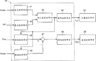
In a linear compressor driving apparatus, a position instructing portion (31) outputs a position instruction value Pref of a piston in accordance with an equation A*sin omega t. A position control portion (33) calculates a speed instruction value Vref. A speed control portion (35) calculates a current instruction value Iref by multiplying a difference between speed instruction value Vref and speed present value Vnow by a constant Gi. A current control portion (37) controls a power source (3) so that current present value Inow becomes equal to the current instruction value Iref. Phase control portion (38) adjusts omega and Gi so as to eliminate phase difference between speed present value Vnow and current instruction value Iref. Since thrust of linear motor can be directly and appropriately controlled in accordance with the load condition, high efficiency is obtained.
Description
The present invention relates to the driving arrangement of Linearkompressor, more particularly, relate to the equipment that drives Linearkompressor, wherein piston is driven by linear motor and moves back and forth in cylinder, to produce Compressed Gas.
Recently, developed a kind of Linearkompressor conduct such as the machinery that in the cooling devices such as refrigerator the coolant gas that has expanded is compressed usefulness.In Linearkompressor, piston is driven Compressed Gas by linear motor and resonance mechanical spring.
In such Linearkompressor, non-linear force (elastic force of gas) is to produce in the compression stage of getting in touch with air-breathing, compression and exhaust phase, and non-linear force because, for example, the variation of load during activation and changing.
But, in traditional Linearkompressor, the basic device of just not controlling linear motor power, and no matter the variation of load provides constant electric power to linear motor without exception.Therefore, the output energy is low with the ratio (hereinafter being called efficient) of input energy always.Although existing people's research can not be satisfactory according to the voltage method of the variation control supply linear motor coil of load.
Therefore, purpose of the present invention and provide a kind of Linearkompressor that can make and obtain high efficiency driving arrangement.
In Linearkompressor driving arrangement according to one aspect of the invention, adopt a kind of multiloop control circuit, it comprises position command/test section, speed command/test section, current-order/test section and Current Control part, and the frequency of adjustment position command value, to eliminate the phase difference between speed currency and the current instruction value.Therefore, can suitably directly control the thrust of linear motor, enable to obtain higher efficient according to loading condition.
Differential is preferably carried out by the testing result to the position detection part in the speed test section, detects the speed of piston.Therefore, the sensor that speed detects usefulness needn't be set separately.
The speed command part preferably multiply by first gain constant with the difference of position command value and position currency, and calculate speed value, the current-order part multiply by second gain constant with the difference of current instruction value and electric current currency, and calculate current instruction value, the gain adjustment member is then adjusted at least one among first and second gain constants, to eliminate the phase difference between speed currency and the current instruction value.Therefore, can adjust the response of Current Control, and more suitably control the thrust of linear motor according to the condition of load.
The speed command part preferably multiply by first gain constant with the difference of position command value and position currency, and calculate speed value, the current-order device multiply by second gain constant with the difference of current instruction value and electric current currency, and calculate current instruction value, the gain adjustment member is then adjusted at least one among first and second gain constants, to eliminate poor between position command value peak value and the position probing value peak value.Therefore, can suitably directly control the thrust of linear motor, enable the efficient that reaches higher according to the condition of load.
The zero crossing of phase difference detection part best detection speed currency and the zero crossing of current instruction value, and poor according to the testing result detected phase.Therefore, the available simple method of phase difference detection part forms.
The peak dot of phase difference detection part best detection speed currency and the peak dot of current instruction value, and poor according to the testing result detected phase.Therefore, the available simple method of phase difference detection part forms.
The amplitude adjustment member is preferably adjusted the partly amplitude of the SIN function of usefulness of position command according to the desired compression gas flow.Thereby, can suitably directly control the thrust of linear motor according to the desired compression gas flow, enable the efficient that reaches higher.
Deviation between Compressed Gas that cooling object is used and the most handy object temperature of desired compression gas flow and the predetermined target temperature is expressed.Therefore object accurately can be cooled to target temperature.
Activate part and preferably adjust the amplitude of the used SIN function of position command part or at least one among the frequency, so that the amplitude of piston increases to desired value gradually when activating.Therefore, can stablize the vibration of piston when activating, thereby avoid the collision of piston head and cylinder.
Shut down part and preferably adjust the amplitude of the used SIN function of position command part and at least one among the frequency, the amplitude of piston is reduced when shutting down gradually, thus the vibration that can also stablize piston when shutting down.
In driving arrangement according to the Linearkompressor of the present invention aspect another, the position command part is sent the piston position instruction by SIN function, current-order partly produces current instruction value, make the position probing value consistent, and power supply is according to drive current of current instruction value output with the position command value.When the phase difference between current instruction value and the piston speed surpassed tolerance limit, FREQUENCY CONTROL partly reduced at least one the extremely predetermined ratio among current instruction value and the SIN function, and the frequency of control SIN function, to eliminate phase difference.When controlled frequency, just correspondingly reduce the amplitude of piston.Therefore,, also can not increase the amplitude of piston, therefore, can avoid the collision of piston head and cylinder inner wall end even when improving efficient by controlled frequency.
Driving arrangement according to the Linearkompressor of another aspect of the present invention, current-order is partly pressed SIN function and is produced current instruction value, and the amplitude of amplitude control section control SIN function, make the piston amplitude detected value consistent with desired value, and power supply according to current instruction value to the linear motor output driving current.When the speed of current instruction value and piston surpassed tolerance limit, FREQUENCY CONTROL partly reduced the amplitude of SIN function to predetermined ratio, and the frequency of control SIN function, to eliminate phase difference.So, can avoid the collision of piston head and cylinder inner wall end, in addition, can simplified structure.
In driving arrangement according to the Linearkompressor of the present invention aspect another, the position command part is sent the piston position instruction by SIN function, and current-order partly produces current instruction value, make the position probing value consistent with the position command value, and power supply according to current instruction value to the linear motor output driving current.Among the amplitude of amplitude control section control SIN function and the amplitude of current instruction value at least one makes bigger in the amplitude of upper and lower dead point side one to meet desired value.Therefore, even the neutral point deviation from origin of piston, piston head can not collide with the cylinder inner wall end yet.
In driving arrangement according to the Linearkompressor of the present invention aspect another, the current-order part produces current instruction value according to SIN function, the amplitude of amplitude control section control SIN function makes that the amplitude detecting value of piston is consistent with desired value, and power supply according to current instruction value to the linear motor output driving current.The amplitude of amplitude control section control SIN function makes bigger in the amplitude of upper and lower dead point one to meet desired value.Therefore, can avoid the collision of piston head and cylinder inner wall end, in addition can simplified structure.
According to driving arrangement according to the Linearkompressor of another aspect of the present invention, the instruction that the position command part is sent piston position by SIN function, current-order partly produces current instruction value, make the position probing value consistent with the position command value, and power supply according to current instruction value to the linear motor output driving current.The side-play amount of side-play amount control section control SIN function is so that eliminate the side-play amount of piston neutral point to initial point.Thereby, can eliminate the side-play amount of piston neutral point to initial point, and, the collision of piston head and cylinder inner wall end can be avoided.Even linear motor is installed two pistons, also can control the cylinder head gap of these two pistons accurately with similar approach.An amplitude detecting part and amplitude control section preferably are set again, amplitude detecting partly detects the amplitude of top dead-centre side and the amplitude of bottom dead centre side, and the amplitude control section, in the amplitude of control SIN function and current instruction value at least one makes bigger among the side amplitude of upper and lower dead point one to meet desired value.Therefore, can avoid the collision of piston head and cylinder inner wall end certainly.
In driving arrangement according to the Linearkompressor of the present invention aspect another, the current-order part produces current instruction value according to SIN function, the amplitude of amplitude control section control SIN function, make the amplitude detecting value of piston meet desired value, and power supply according to current instruction value to the linear motor output driving current.The side-play amount of side-play amount control section control SIN function is so that eliminate the side-play amount of piston neutral point to initial point.Thereby, can eliminate the side-play amount of piston neutral point to initial point, and, the collision of piston head and cylinder inner wall end can be avoided.Even linear motor is installed two pistons, also can control the cylinder head gap of these two pistons accurately with similar approach.In addition, can simplified structure.
Amplitude detecting part best detection top dead-centre side amplitude and bottom dead centre side amplitude, and the amplitude of amplitude control section control SIN function make the big person among the side amplitude of upper and lower dead point meet desired value.Therefore, can avoid the collision of piston head and cylinder inner wall end certainly.
In driving arrangement according to the Linearkompressor of the present invention aspect another, detect the open cycle of air bleeding valve, and the cycle internal cutting off drive current of stipulating according to testing result.Thereby, the idle current different can be eliminated, thereby the efficient higher can be obtained than prior art with the piston speed phase place.
Preferably adopt the current-control type power supply, and directly output current is controlled.So, can control highly accurately.
Preferably adopt the voltage-controlled type power supply, the electric current that flows to linear motor from power supply is controlled with switch.Thereby, with simple structure control electric current.
Cut off drive current when being preferably in exhaust valve opening.Thereby, can obtain high efficiency by simple control.
Consult below in conjunction with accompanying drawing being described in detail that the present invention carries out, above-mentioned purpose, feature, aspect and advantage with other of the present invention will become more apparent.
Fig. 1 is a block diagram of representing the structure of Linearkompressor control appliance according to a first embodiment of the invention;
Fig. 2 is the profile of the structure of expression Linearkompressor shown in Figure 1;
Fig. 3 is the block diagram of the structure of expression control appliance shown in Figure 1;
Fig. 4 is the flow chart of the operation of expression control appliance shown in Figure 3;
Fig. 5 is that expression is included in the block diagram according to the control appliance in the Linearkompressor driving arrangement of second embodiment of the invention;
Fig. 6 is the block diagram of the structure of expression phase control part shown in Figure 5;
Fig. 7 is the flow chart of the operation of expression control appliance shown in Figure 5;
Fig. 8 is the block diagram of expression according to the phase control part of the Linearkompressor driving arrangement of third embodiment of the invention;
Fig. 9 is the flow chart that expression is included in the operation of the control appliance in the Linearkompressor driving arrangement of describing with reference to Fig. 8;
Figure 10 is that expression is included in the block diagram according to the structure of the control appliance in the Linearkompressor driving arrangement of four embodiment of the invention;
Figure 11 is the flow chart of the operation of expression Figure 10 control appliance;
Figure 12 is that expression is included in the block diagram according to the structure of the control appliance in the Linearkompressor driving arrangement of fifth embodiment of the invention;
The operation of the position command part that forms among Figure 12 when Figure 13 represents to activate;
The operation of position command part shown in Figure 12 when Figure 14 represents to shut down;
Figure 15 is the flow chart of the operation of expression control appliance shown in Figure 12;
Figure 16 is the continuation of Figure 15;
Figure 17 is the block diagram of expression according to the structure of the Linearkompressor driving arrangement of sixth embodiment of the invention;
Figure 18 is the block diagram of the structure of expression control appliance major part shown in Figure 17;
Figure 19 is the flow chart of the operation of expression control appliance shown in Figure 180;
Figure 20 is the continuation of Figure 19;
Figure 21 is the block diagram of expression according to the major part of the control appliance of the Linearkompressor driving arrangement of seventh embodiment of the invention;
Figure 22 is the flow chart of the operation of expression control appliance shown in Figure 21;
Figure 23 is the continuation of Figure 22;
Figure 24 is the block diagram of structure of the control appliance major part of the expression Linearkompressor driving arrangement of executing example according to the 8th of the present invention;
Figure 25 is the flow chart of the operation of expression control appliance shown in Figure 24;
Figure 26 is the continuation of Figure 25;
Figure 27 is the improved profile of expression Linearkompressor driving arrangement shown in Figure 24;
Figure 28 is the oscillogram that Linearkompressor shown in the expression 27 concerns between piston speed v and the drive current i when non-loaded;
Figure 29 is the oscillogram that Linearkompressor shown in the expression 27 concerns between piston speed v and the drive current i when load is arranged;
Figure 30 is the block diagram of expression according to the structure of the Linearkompressor driving arrangement of ninth embodiment of the invention;
Figure 31 is the circuit diagram of expression inverter structure shown in Figure 30;
Figure 32 is the flow chart of the operation of expression control appliance shown in Figure 30;
Figure 33 is the oscillogram of expression Linearkompressor driving arrangement shown in Figure 30 effect;
Figure 34 is the block diagram of expression according to the structure of the Linearkompressor driving arrangement of tenth embodiment of the invention;
Figure 35 is the flow chart of the operation of expression control appliance shown in Figure 34.
[first embodiment]
Fig. 1 is the block diagram of structure of representing the driving arrangement 2 of Linearkompressor 1 usefulness according to a first embodiment of the invention.
With reference to Fig. 1, driving arrangement 2 comprises power supply 3, current sensor 4, position sensor 5 and control appliance 6.Power supply 3 provides drive current I to the linear motor of Linearkompressor 1.Current sensor 4 detects the currency Inow of power supply 3 output currents.Position sensor 5 detects the currency Pnow of Linearkompressor 1 piston position directly or indirectly.Control appliance 6 is exported control signal φ c according to the electric current currency Inow of current sensor 4 detections and the position currency Pnow of position sensor 5 detections to power supply 3, and the output current I of control power supply 3.
Fig. 2 is the profile of expression Linearkompressor 1 structure.With reference to Fig. 2, Linearkompressor 1 comprises two cylinder 11a being located at cylinder baffle 10 top and bottom respectively and 11b, is contained in two piston 12a in cylinder 11a and the 11b and 12b, two compression stroke 13a that form in the face of piston 12a and 12b head respectively and 13b respectively, and two cover intake valve 14a and 14b and air bleeding valve 15a and 15b, they are respectively according to the gas pressure in the compression stroke and opening/closing.
Two piston 12a and 12b are contained in an end and the other end of an axle 16 respectively.Axle 16 is by two groups of linear ball bearing 17a, and 17b and coil spring 18a and 18b support, and makes it possible to move back and forth in cylinder 11a and 11b and shell 10.In the space that forms by piston 12a and 12b back head and cylinder 11a and 11b, be provided with gas leak 19a and 19b, to prevent irreversible compression.
In addition, Linearkompressor 1 comprises linear motor 20, is used for making axle 16 and piston 12a and 12b reciprocating.Linear motor 20 is the controlled voice coil motors of a kind of height, and stationary part that comprises the standing part that contains yoke part 10a and permanent magnet 21 and the movable part that comprises coil 23 and cylindrical supporter 24 are housed.Yoke part 10a forms the part of shell 10.Permanent magnet 21 is contained in the inner peripheral wall of yoke part 10a.Supporter 24 1 ends are can reciprocating mode inserting between permanent magnet 21 and the cylinder 11a outer circle wall, and the other end is fixed on the core of axle 16.Coil 23 is installed in the position of described supporter one end in the mode facing to permanent magnet 21.Power supply 3 is connected with coil 23 by the electric lead 25 of helical spring shape.
Fig. 3 is the block diagram of the structure of expression control appliance 6 shown in Figure 1.With reference to Fig. 3, control appliance 6 comprises that p-v conversion portion 30, position command part 31, three subtracters 32,34 and 36, Position Control part 33, speed controlling portions divide 35, Current Control part 37 and phase control part 38.30 pairs of position sensors of p-v conversion portion, 5 detected position currency Pnow carry out differential, calculate speed currency Vnow.Position command part 31 is according to equation Pref=A
*Sin ω t (A represents amplitude in the formula, and ω represents angular frequency), Pref is added to subtracter 32 with the position command value.The position command value Pref that provided by position command part 31 and the difference Pref-Pnow of position sensor 5 detected position currency Pnow are provided for subtracter 32, and result of calculation Pref-Pnow is added to Position Control part 33.
Position Control part 33 is according to equation Vref=Gv
*(Pref-Pnow) (Gv represents gain constant in the formula) computational speed command value Vref, and result of calculation Vref is added to subtracter 34.Subtracter 34 calculates the difference Vref-Vnow between the speed currency Vnow that produces from the speed value Vref of Position Control part 33 and p-v conversion portion 30, and result of calculation Vref-Vnow is added to speed controlling portion divides 35.
Speed controlling portion divides 35 according to equation Iref=(Vref-Vnow) (Gv represents gain constant in the formula) calculating current instruction value Iref, and result of calculation Iref is added to subtracter 36.Subtracter 36 calculates from speed controlling portion and divides 35 current instruction value Iref and the difference Iref-Inow between the current sensor 4 detected electric current currency Inow, and result of calculation Iref-Inow is added to Current Control part 37.
Current Control part 37 applies control signal φ c by giving power supply 3, and the output current I of control power supply 3 makes the output Iref-Inow of subtracter 36 reach 0.The control of power supply 3 output current I be according to, for example, PWM (pulsewidth modulation) or PAM (pulse amplitude modulation) method are finished.
Speed currency Vnow that phase control part 38 detection p-v conversion portions 30 produce and speed controlling portion divide the phase difference between the 35 current instruction value Iref that produce, and adjust the equation Pref=A that uses in the position command part 31
*Angular frequency among the sin ω t and speed controlling portion divide the equation Iref=Gi that uses in 35
*(Vref-Vnow) gain constant Gi is to eliminate this phase difference.
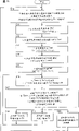
Fig. 4 is the flow chart of the operation of expression control appliance 6 shown in Figure 3.Now with reference to this flow chart, introduce the operation of Linearkompressor 1 shown in Fig. 1 to 3 and used control appliance thereof briefly.
At first, on step S1, position command part 31 produces position command value Pref, and Position Control part 33 produces speed value Vref, and speed controlling portion divides 35 to produce current instruction value Iref.When the coil 23 of giving linear motor 20 provided electric current, the movable part of linear motor 20 began reciprocating, so begin to produce Compressed Gas.
On step S2, position sensor 5 detection position currency Pnow, and detected position currency Pnow added to subtracter 32 and p-v conversion portion 30.On step S3, Position Control part 33 computational speed command value Vref=Gv
*And on step S4, p-v conversion portion 30 converts position currency Pnow to speed currency Vnow (Pref-Pnow).Speed currency Vnow adds to subtracter 34 and phase control part 38.
On step S5, speed controlling portion divides 35 to calculate current instruction value Iref=Gi
*(Vref-Vnow), and with calculated value Iref add to subtracter 36 and phase control part 38.Current Control part 37 control power supplys 3 make electric current currency Inow consistent with current instruction value Iref.
On step S6, the phase difference between phase control part 38 detection speed currency Vnow and the current instruction value Iref.On step S7, phase control part 38 is adjusted the angular frequency of gain constant Gi and position command value Pref, to eliminate the phase difference between speed currency Vnow and the current instruction value Iref.
After this, repeating step S1 to S7, the mode of operation of regulated linear compressor 1 rapidly.Even when having the hunting of load after the activation, also can suitably directly control the thrust of linear motor 20, that is drive current I enables to reach high efficiency.
Although in the present embodiment, position currency Pnow is detected by position sensor 4, and speed currency Inow comes out by the differential calculation to detected value, but, also can install velocity sensor and replace position sensor 4, position currency Pnow can be by coming out to the integral and calculating of detected value Vnow.Perhaps, can installation position and velocity sensor.
In the present embodiment, divide at the gain constant Gv of position control section 33 and speed controlling portion among 35 the Gi, 38 of phase control parts are adjusted gain constant Gi.But, also can only adjust gain constant Gv, perhaps all adjust for two.
[second embodiment]
Fig. 5 is a block diagram, and expression is included in the structure according to control appliance 39 in the driving arrangement of Linearkompressor 1 usefulness of second embodiment of the present invention, corresponding with Fig. 3.
With reference to Fig. 5, control appliance 39 is that with control appliance 6 differences shown in Figure 3 phase control part 40 has replaced phase control part 38.
With reference to Fig. 6, phase control part 40 comprise zero point test section 41 and 42, phase-detection part 43, FREQUENCY CONTROL part 44, peak value test section 45 and 46, subtracter 47 and control portion of gain divide 48.
The zero crossing of the speed currency Vnow of test section 41 detection p-v conversion portions 30 generations at zero point.Zero point test section 42 detection speed control sections 35 added current instruction value Iref zero crossing.Zero point sampled to speed currency Vnow with the enough short sampling period in specific rate currency Vnow sampling period in test section 41, and the product that detects last sampled value and this sampled value is a negative value, and this sampled value be on the occasion of the fact, for example, with the fact of this detection speed currency through zero crossing.Zero point, test section 42 working method was similar.
Phase difference detection part 43 according to zero point test section 41 detected speed currency Vnow zero crossing and zero point test section 42 detected current instruction value Iref zero crossing, come the phase difference between detection speed currency Vnow and the current instruction value Iref.FREQUENCY CONTROL part 44 is adjusted the equation Pref=A that uses in the position command part 31
*The angular frequency of sin ω t is to eliminate the phase difference between phase difference detection part 43 detected speed currency Vnow and the current instruction value Iref.
The phase place command value Pref that peak value test section 45 is received in the phase difference between phase difference detection part 43 detected speed currency Vnow and the current instruction value Iref and calculates in position operation part 31, and the detected phase difference is the peak value of 0 o'clock position command value Pref.The position currency Pnow that phase difference between peak value test section 46 receiving phase difference test sections, 43 detected speed currency Vnow and the current instruction value Iref and position sensor 5 detect, and the detected phase difference is the peak value of 0 o'clock position currency Pnow.
Peak value and the difference between the peak value of peak value test section 46 detected position currency Pnow that subtracter 47 calculates at peak value test section 45 detected position command value Pref.Control portion of gain divides the 48 used equation Iref=Gi of control section that regulate the speed
*(Vref-Vnow) gain constant Gi makes the calculated value of subtracter 47 reach 0.Except these some, this operation is identical with Linearkompressor driving arrangement according to first embodiment, so repeat no more.
Fig. 7 is a flow chart, the operation of control appliance 39 shown in the presentation graphs 5 and 6.Referring now to this flow chart, introduce the Linearkompressor 1 of present embodiment and the operation of driving arrangement thereof briefly.
At first, on step S11, position command part 31 produces position command value Pref, and Position Control part 33 produces speed value Vref, and speed controlling portion divides 35 to produce current instruction value Iref.When electric current was transported to the coil 23 of linear motor 20, the movable part of linear motor 20 began reciprocating, so begin to produce Compressed Gas.
On step S12, position sensor 5 detection position currency Pnow, detected position currency Pnow is sent to p-v conversion portion 30, subtracter 32 and phase control part 40.On step S13, Position Control part 33 computational speed command value Vref=Gv
*And on step S14, p-v conversion portion 30 converts position currency Pnow to speed currency Vnow (Pref-Pnow).Speed currency Vnow gives subtracter 34 and phase control part 40.
On step S15, speed controlling portion divides 35 to calculate current instruction value Iref=Gi
*(Vref-Vnow), and with calculated value Iref give subtracter 36 and phase control part 40.Current Control part 37 control power supplys 3 make electric current currency Inow consistent with current instruction value Iref.
On step S16, zero point test section 41 and 42 detection speed currency Vnow zero crossing and the zero crossing of current instruction value Iref, and the phase difference between phase difference detection part 43 detection speed currency Vnow and the current instruction value Iref.
On step S17, the angular frequency of FREQUENCY CONTROL part 44 control position command value Pref, making the phase difference between speed currency Vnow and the current instruction value Iref is 0.When the phase difference between speed currency Vnow and the current instruction value Iref reached 0, peak value test section 45 and 46 is the peak value of the peak value of detection position command value Pref (desired value) and position currency Pnow correspondingly respectively.Control portion of gain divides 48 to determine whether the peak value of position currency Pnow equals desired value.
When the peak value of position currency Pnow during less than desired value, on step S18, control portion of gain divides 48 to increase gain G i, and when the peak value of position currency Pnow during greater than desired value, on step S19, control portion of gain divides 48 to reduce gain G i.
Repeating step S16 to S19 equals desired value until the peak value of position currency Pnow.On step S20, when the peak value of position currency Pnow equaled desired value, flow process was returned step S11.
After this, repeating step S11 to S20 makes the mode of operation of Linearkompressor 1 stable rapidly.Even after activating the hunting of load is arranged, also can suitably directly control the thrust of linear motor 20, that is drive current I enables to reach high efficiency.
In the present embodiment, divide at the gain constant Gv of position control section 33 and speed controlling portion among 35 the Gi, 40 of phase control parts are adjusted gain constant Gi.But also can only adjust gain constant Gv wherein, perhaps all adjust for two.
[the 3rd embodiment]
Fig. 8 represents to be included in the structure according to the phase control part 50 in the driving arrangement of Linearkompressor 1 usefulness of the 3rd embodiment of the present invention, and is corresponding with Fig. 6.
With reference to Fig. 8, phase control part 50 is with phase control part 40 differences of Fig. 6, and zero point, the test section 41 and 42 was replaced by peak dot test section 51 and 52 respectively.
The peak dot of the speed currency Vnow of p-v conversion portion 30 generations is detected in peak dot test section 51.The peak dot that is divided 35 added current instruction value Iref by speed controlling portion is detected in peak dot test section 52.Sampled to speed currency Vnow with the sampling period of comparing enough weak points with the sampling period of speed currency Vnow in peak dot test section 51, and detect last sampled value greater than last sampled value and this sampled value have been passed through peak dot less than the fact of last sampled value with this detection speed currency again.The working method of peak dot test section 52 is similar.
On step S26, phase difference detection part 43 is according to the peak dot of speed currency Vnow and the peak dot of current instruction value Iref, the phase difference between detection speed currency Vnow and the current instruction value Iref.Step 21 to 25 with 27 to 30 respectively with Fig. 7 in step 11 to 15 and 17 to 20 identical, so repeat no more.
Present embodiment can obtain and second effect that embodiment is similar.
[the 4th embodiment]
Figure 10 is a block diagram, and expression is included in the structure according to the control appliance 53 in the driving arrangement of Linearkompressor 1 usefulness of the 4th embodiment of the present invention, and is corresponding with Fig. 5.With reference to Figure 10, control appliance 53 is that with control appliance 39 differences of Fig. 5 position command part 31 is replaced by position command part 54.
Position command part 54 is according to the deviation delta T=Tref-Tnow between the added refrigerator temps Tnow of temperature regulating equipment (not shown) in target temperature Tref in the refrigerator and the refrigerator, and according under the 1 calculated capacity control ratio of tabulating.Volume controlled is than the ratio (%) of the output that is defined as Linearkompressor 1 for maximum output.In Linearkompressor 1, output is directly proportional with piston 12a and 12b stroke, and when at least 2 ℃ of temperature deviations, the volume controlled ratio reaches 100%, and as if temperature deviation maximum-5 ℃, then the volume controlled ratio reaches 0%.In addition, than the stroke that calculates piston 12a and 12b, in other words, amplitude A is according to amplitude A, angular frequency and equation Pref=A according to volume controlled for position command part 54
*Sin ω t produces position command value Pref, and position command value Pref is added to subtracter 32.
Table 1
The deviation volume controlled is than piston stroke desired value
(maximum 100%) (to the ratio % of full stroke)
At least 2 ℃ 100% 100%
At least 0 ℃ 75% 75%
At least-2 ℃ 50% 50%
At least-5 ℃ 25% 25%
At the most-5 ℃ 0% 0%
Figure 11 is a flow chart, represents the operation of control appliance 53 shown in Figure 10, corresponding to Fig. 7.
With reference to Figure 11, the difference of the flow chart of this flow chart and Fig. 7 is before the step S11, on step S10, position command part 54 is according to the amplitude A of target temperature Tref in the refrigerator and the deviation delta T=Tref-Tnow calculating location command value Pref between the temperature T now in the refrigerator.
Identical with second embodiment of other structure and operation is so repeat no more.
Though the present invention in the present embodiment is applicable to the Linearkompressor 1 of used for refrigerator, use and be not limited to this, the present invention can also be applied to the Linearkompressor 1 of any purposes.For example, to be used for air-conditioning be effective to Linearkompressor 1.Under the sort of situation, Linearkompressor 1 can be controlled according to the deviation delta T=Tref-Tnow between room temperature desired value Tref and the room temperature Tnow.
[the 5th embodiment]
Figure 12 is a block diagram, and expression is included in the structure according to the control appliance 55 in the driving arrangement of Linearkompressor 1 usefulness of the 5th embodiment of the present invention, and is corresponding with Fig. 3.
With reference to Figure 12, control appliance 55 is that with control appliance 6 differences of Fig. 3 position command part 31 is replaced by position command part 56.
Position command part 56 is according to amplitude A, angular frequency and equation Pref=A
*Sin ω t produces position command value Pref.Under active mode, under the stable operation mode and under halt mode with diverse ways control with amplitude A and angular frequency are set.
More particularly, under active mode, the little value of the resonant frequency when frequency f=ω of position command value Pref/2 π are configured to be about no gas load (for example, 30Hz).Like this, efficient is depressed, and can prevent that the stroke of piston 12a and 12b from increasing rapidly.Amplitude A is according to piston 12a, and the stroke of 12b is than Rs, full stroke Amax and equation A=Rs
*Amax calculates.As shown in figure 13, the variation of each position currency Pnow peak value is stabilized at 1 o'clock from 0, progressively increases stroke and compares Rs.Step number is set to rule of thumb definite in advance value.
Under the mode of stable operation, peak A is calculated according to volume controlled.For example, if Compressed Gas is used for the cooling of refrigerator, then peak A is calculated according to target temperature Tref in the refrigerator and the deviation between the temperature T now in the refrigerator.Phase control part 38 pilot angle frequencies omega make the phase place of current instruction value Iref consistent with the phase place of speed currency Vnow.Therefore, even load variations always can obtain high efficiency.
Under halt mode, according to frequency ratio Rf, just change angular frequency 0 and equation ω=Rf before the halt mode over to
* ω 0 calculates angular frequency.The setting of response halt mode constantly reduces frequency ratio Rf moderately.Frequency ratio Rf is predisposed to the value of rule of thumb calculating.Therefore, efficient reduces moderately, and the stroke of piston 12a and 12b reduces gradually.When the stroke of piston 12a and 12b reaches half left and right sides of full stroke, cut off the electricity supply 3.
Figure 15 and 16 is flow charts, the operation of expression control appliance 55.Now introduce briefly by the Linearkompressor 1 of present embodiment and the operation of used driving arrangement thereof with reference to this flow chart.
When specifying activation Linearkompressor 1 or active mode be set, on step S31, near the little value when position command part 56 is arranged to the frequency of position command value Pref not have gas load the resonant frequency.
On step S32, position command part 56 is according to the amplitude A=Rs of stroke than Rs calculating location command value Pref
*Amax, and on step S33, position command part 56 produces position command value Pref=A
*Sin ω t.
On step S34, position sensor 5 detection position currency Pnow, and detected position currency Pnow added to subtracter 32 and p-v conversion portion 30.On step S35, Position Control part 33 computational speed command value Vref=Gv
*And on step S36, p-v conversion portion 30 converts position currency Pnow to speed currency Vnow (Pref-Pnow).Speed currency Vnow adds to subtracter 34 and phase control part 38.
On step S37, speed controlling portion divides 35 to calculate current instruction value Iref=Gi
*(Vref-Vnow), and the value Iref that will calculate add to subtracter 36 and phase control part 38.Current Control part 37 control power supplys 3 make electric current currency Inow consistent with current instruction value Iref.Therefore, when the coil 23 to linear motor 20 provided electric current, the movable part of linear motor 20 began to move back and forth, so begin to produce Compressed Gas.
On step S38, when position command part 56 settled out at the peak deviation of position currency Pnow, stroke increased a step than Rs, and repeating step S31 to S38 reaches till 1 than Rs until stroke then.
On step S39, when stroke reaches 1 and the peak change of position currency Pnow when settling out than Rs, the cancellation active mode is provided with the stable operation mode.
On step S40, position command part 56 is calculated the amplitude A of the position command value Pref corresponding with volume controlled.Step S41 to S45 is identical with step S33 to S37.More particularly, on step S41, position command part 56 produces position command value Pref=A
*Sin ω t, on step S42, position sensor 5 detection position currency Pnow, and on step S43, Position Control part 33 computational speed command value Vref.On step S44, p-v conversion portion 30 produces speed currency Vnow, and on step S45, speed controlling portion divides 35 to calculate current instruction value Iref.Control power supply 3 makes electric current currency Inow consistent with current instruction value Iref.
On step S46, the phase difference between phase control part 38 detection speed currency Vnow and the current instruction value Iref.On step S47, phase control part 38 is adjusted the angular frequency of ride gain constant Gi and position command value Pref, to eliminate the phase difference between speed currency Vnow and the current instruction value Iref.After this, under the stable operation mode, repeating step S40 to S47.
When appointment stops Linearkompressor 1, cancellation stable operation mode, and halt mode is set, on step S48, position command part 56 is according to angular frequency=Rf of frequency ratio Rf calculating location command value Pref
*ω 0.
Step S49 to S53 is identical with step S33 value S37.More particularly, on step S49, position command part 56 produces position command value Pref=A
*Sin ω t, on step S50, position sensor 5 detection position currency Pnow, and on step S51, Position Control part 33 computational speed command value Vref.On step S52, p-v conversion portion 30 produces speed currency Vnow, and on step S53, speed controlling portion divides 35 to calculate current instruction value Iref.Control power supply 3 makes electric current currency Inow consistent with current instruction value Iref.
On step S54, position command part 56 constantly reduces frequency ratio Rf moderately, and repeating step S48 to S54 then is till the stroke of position command value Pref reaches half of full stroke approximately.
On step S55, when the stroke of position currency Pnow reaches a half of full stroke approximately, position command part 56 cuts off the electricity supply 3.
Though in the present embodiment, the angular frequency of position command value Pref is set to little value when activating, and the amplitude A of position command value Pref progressively increases, and its mode of operation is not limited thereto.The randomly angular frequency of control position command value Pref and at least one among the amplitude A are as long as the stroke of piston 12a and 12b can progressively increase.For example, angular frequency can be arranged to the resonance value, progressively increase amplitude A then.
Though in the present embodiment, during shutdown, reduce the angular frequency of position command value Pref moderately, be not limited thereto.The randomly angular frequency of control position command value Pref and at least one among the amplitude A are as long as the stroke of piston 12a and 12b can progressively reduce.For example, can only reduce amplitude A, and not reduce angular frequency.
[the 6th embodiment]
In such Linearkompressor, when the drive current and the same phase time of piston speed of linear motor, obtain high efficiency, and in the top clearance when (minimum distance between piston head and the cylinder inner wall end) keeps minimum of a value (about 0.1mm), acquisition most effective.
Therefore, can control the frequency of drive current, make the phase place of drive current of linear motor consistent with the phase place of piston speed.But, if the frequency of control drive current, and minimum of a value (for example, about 0.1mm) is kept in the top clearance simultaneously, just can improve loss, and the amplitude of piston becomes big, causes the problem of piston head collision cylinder inner wall end.
Amplitude that can control piston makes the top clearance have minimum of a value.But in the Linearkompressor that two pistons are arranged, because valve etc. is asymmetric, the neutral point of piston reality may be towards the last or bottom dead centre lateral deviation neutral point (initial point) from design.In such cases, be difficult to control simultaneously the top clearance of two pistons with high accuracy.
These problems will be solved in the present embodiment.
Figure 17 is a block diagram, and expression is according to the structure of the driving arrangement 57 of Linearkompressor 1 usefulness of sixth embodiment of the invention.
With reference to Figure 17, driving arrangement 57 comprises power supply 3, position sensor 5 and control appliance 58.Power supply 3 provides drive current I to the linear motor of Linearkompressor 1.Position sensor 5 detects Linearkompressor 1 position of piston directly or indirectly, and exports signal of telecommunication Pa according to piston position to control appliance 58.Can use laser displacement gauge as position sensor 5.Control appliance 58 is exported control signal φ c according to the output of position sensor 5 to power supply 3.
Figure 18 is a block diagram, represents the structure of control appliance 58 major parts shown in Figure 17.With reference to Figure 18, control appliance 58 comprises that the position command value produces part 60, position and speed control section 61, current instruction value generation part 62, position and speed test section 63, test section, upper and lower dead point 64, rate of current phase difference detection part 65, current gain control section 66, amplitude neutral position control section 67 and FREQUENCY CONTROL part 68.
Position and speed test section 63 with sampling period of comparing enough weak points cycle of oscillation of piston 12a and 12b (for example, 150 microseconds) output of position sensor 5 is sampled, and by A/D conversion generation position currency Pnow, and by differential calculation speed currency Vnow to position currency Pnow to sampled value.
Maximum and the minimum of a value of the position currency Pnow that test section, dead point, up and down 64 is produced according to position and speed test section 63 detect the amplitude of the top dead-centre side between the initial point of top dead-centre and piston 12a and 12b and the amplitude of the bottom dead centre side between bottom dead centre and the described initial point.When the detection of upper and lower dead point side amplitude is finished at each position command value Pref one-period, undertaken when just each position command value Pref is by zero crossing.
Phase difference between the current instruction value Iref that speed currency Vnow that speed test section, rate of current phase difference detection part 65 detection position 63 produces and position command value generation part 62 produce.When the detection of phase difference finishes at each position currency Pnow one-period, undertaken when just each position currency Pnow is by zero crossing.
The position command value produces part 60 according to the sine table, amplitude A, angular frequency, side-play amount B and the equation Pref=A that are stored in memory
*Sin ω t+B (SIN function) produces position command value Pref, and the position command value Pref that produces is added to position and speed control section 61.
Position and speed control section 61 produces speed value Vref according to the deviation Pref-Pnow that the position command value produces between the position currency Pnow that position command value Pref that part 60 produces and position and speed test section 63 produce, and according to the deviation Vref-Vnow generation speed controlling value Vc between the speed currency Vnow of speed value Vref and 63 generations of position and speed test section.
Current instruction value produces part 62 and produces current instruction value Iref according to speed controlling value Vc, current gain Gi and the equation Iref=GiVc that position and speed control section 61 produces, and converts current instruction value Iref to control signal φ c, and adds to power supply 3.To control, for example, carry out according to pulsewidth modulation (PWM) method or pulse-amplitude modulation (PAM) method from the output current I of power supply 3.
The amplitude of test section, current gain control section 66 more upper and lower dead point 64 detected top dead-centre sides and the amplitude of bottom dead centre side, and the greater in the amplitude of upper and lower dead point side is considered as peak swing currency Anow.Current gain control section 66 is used for the current gain value Gi that current instruction value produces part 62, the peak swing desired value Aref that makes peak swing currency Anow equal to be scheduled in each vibration period control of piston 12a and 12b.In addition, current gain control section 66 (for example passes through hundreds of at piston 12a and 12b, 300) determine whether the phase difference that detects primary current velocity phase difference test section 65 surpasses predetermined tolerance limit during individual vibration period, if surpassed, the current gain value Gi that then current instruction value is produced part 62 usefulness reduces a few percent.Because position and speed control section 61 is except controlling position and speed, also peak swing is controlled, and before carrying out FREQUENCY CONTROL, current gain is reduced several percentage points, so can avoid the head of piston 12a and 12b and the collision of cylinder 11a and 11b inwall end certainly.
Amplitude neutral position control section 67 is compared top dead-centre side amplitude and the bottom dead centre side amplitude that upper and lower dead point side amplitude detecting part 64 detects, and when each position command value Pref finishes one-period, control the side-play amount B that the position command value produces part 60 usefulness, the difference between the side amplitude of upper and lower dead point is reduced.More particularly, when top dead-centre side amplitude during greater than bottom dead centre side amplitude, amplitude neutral position control section 67 is revised side-play amount B towards minus side (lower direction), and top dead-centre side amplitude is during less than bottom dead centre side amplitude, and amplitude neutral position control section 67 is revised side-play amount B towards positive side (higher direction).The side-play amount B that causes owing to the characteristics such as the valve asymmetry by equipment is a constant haply, so the controlled quentity controlled variable of side-play amount B is arranged to little value (for example, 1 is trifling) at every turn.Because side-play amount B is control like this, the top clearance of two pistons just can be controlled similarly accurately.
Whether the phase difference that FREQUENCY CONTROL part 66 detects 65 detections of rate of current phase difference detection part surpasses predetermined tolerance limit, if surpassed, then proofreaies and correct the angular frequency that is used for position command value generation part 60 usefulness, to eliminate phase difference.The correction of phase difference reduces several percentage points with current gain control section 66 with current gain Gi substantially and carries out simultaneously.Therefore, the amplitude of piston 12a and 12b strengthens the piston 12a that causes and the collision of 12b head and cylinder 11a and 11b inwall end in the time of can avoiding improving efficient owing to phasing.
Figure 19 and 20 is flow charts, the operation of the control appliance 58 of expression Figure 18.Press the operation of the Linearkompressor 1 and the driving arrangement 57 thereof of present embodiment referring now to this flow chart description.
At first, the position command value produces part 60 and produces position command value Pref, and position and speed control section 61 produces speed controlling value Vc, and current instruction value produces part 62 and produces control signal φ c.When power supply 3 when the coil 23 of linear motor 20 provides electric current, the movable part of linear motor 20 begins to move back and forth, so begin to produce Compressed Gas.
On step S61, position data is read in position and speed test section 63, that is the output of position sensor 5, and on step S62, position and speed test section 63 calculating location currency Pnow and speed currency Vnow.
On step S63, position and speed control section 61 is finished speed control.More particularly, position and speed control section 61 is according to the deviation computational speed controlling value Vc between speed value Vref and the speed currency Vnow, and it is added to current instruction value produces on the part 62.
On step S64, current instruction value produces part 62 and produces current instruction value Iref, it is the product of speed controlling value Vc and current gain Gi, and on step S65, current instruction value produce part 62 according to current instruction value Iref the current-order data, that is control signal φ c exports to power supply 3.
On step S66, the count value that is included in the first counter (not shown) in the control appliance 58 adds one (+1), and on step S67, determines whether the count value of first counter reaches setting value (for example, 3).
If the count value of first counter reaches setting value on step S67, then on step S68, the position correction amount and the frequency setting value that produce in the part 60 according to the position command value produce amplitude A and angular frequency, in addition, produce position command value Pref=Asin ω t+B according to sine table, amplitude A, side-play amount B and angular frequency.On step S69, the control of position and speed control section 61 completing places.More particularly, position and speed control section 61 produces speed value Vref according to the deviation between position command value Pref and the position currency Pnow.After the completing place control, on step S70, the count value of first counter is resetted.
On step S67, if the count value of first counter does not reach setting value as yet, execution in step 68 to 70 not then.
On step S71, determine whether the one-period of position command value Pref finishes.
On step S71, if the one-period of position command value Pref finishes, then on step S72, piston 12a and 12b top dead-centre side amplitude and bottom dead centre side amplitude are detected according to maximum and the minimum of a value of position currency Pnow in side test section, dead point, up and down 64.
On step S73, the value of more upper and lower dead point side amplitude, when top dead-centre side amplitude during greater than bottom dead centre side amplitude, on step S74, amplitude neutral position control section 67 is made as negative correcting value the correcting value of side-play amount B, and on step S75, top dead-centre side amplitude is made as peak swing currency Anow.
Comparative result as the value of step 73, when bottom dead centre side amplitude during greater than top dead-centre side amplitude, on step S76, amplitude neutral position control section 67 is made as positive correcting value the correcting value of side-play amount B, and on step S77, bottom dead centre side amplitude is made as peak swing currency Anow.
On step S78, current gain control section 66 is controlled and current gain Gi is set, and makes peak swing currency Anow consistent with peak swing desired value Aref, and after this on step S79, in test section, dead point, up and down 64, maximum and the minimum of a value of position currency Pnow resetted.
Finish if on step S71, determine the one-period of position command value Pref, then execution in step S72 to S79 not.
After this, on step S80, maximum and the minimum of a value with holding position currency Pnow detected in test section, dead point, up and down 64.On step S81, rate of current phase difference detection part 65 determines whether the one-period of position currency finishes.
Finish if on step S81, determine the one-period of position currency, then on step S82, the phase difference that rate of current phase difference detection part 65 detects between current instruction value Iref and the speed currency Vnow.
After this, on step S83, the count value (not shown) of second counter is added one, on step S84, determine whether the count value of second counter reaches setting value (300).
Reached setting value if on step S84, determine the count value of second counter, then on step S85, determined that phase difference between current instruction value Iref and the speed currency Vnow is whether within marginal range.
If determine that on step S85 phase difference exceeds tolerance limit, on step S86, the frequency of position command value Pref is controlled and be provided with to FREQUENCY CONTROL part 68, and on step S87, current gain control section 66 reduces several percentage points with the current gain Gi of current instruction value Iref.
If on step S85, determine phase difference in tolerance limit, then not execution in step S86 and S87.
After this, on step S88, the count value of second counter is resetted.Finish as yet if on step S81, determine the one-period of position currency Vnow, then execution in step S82 to S88 not.Do not reach setting value as yet if on step S84, determine the count value of second counter, then execution in step S85 to S88 not.
After this, on step S89, determine whether control is finished, and finished, then finishing control as if definite control.If do not finish as yet, then flow process is returned step S61.
In the present embodiment, when and during the frequency of control position command value Pref, the current gain Gi of Current Control value Iref=GiVc is reduced several percentage points in order to eliminate phase difference between current instruction value Iref and the speed currency Vnow.Therefore, even improve loss and increase piston 12a and the amplitude of 12b, also can avoid the inwall end of piston 12a and 12b head and cylinder 11a and 11b to collide by the FREQUENCY CONTROL of position command value Pref.
In addition, the current gain Gi of control current instruction value Iref, big person among the side amplitude of the upper and lower dead point of piston 12a and 12b is positioned on the peak swing desired value Aref, therefore, even the physical location off-design neutral point (initial point) of the neutral point of piston 12a and 12b also can be avoided the inwall end collision of piston 12a and 12b head and cylinder 11a and 11b.
In addition, detect the side-play amount B that piston 12a and the actual neutral point of 12b leave initial point, and the side-play amount B of control position command value Pref, with elimination side-play amount B, therefore, the gap of two piston 12a and 12b head can both highly precisely be controlled with similar approach.
In the present embodiment, the phase difference that rate of current phase difference detection part 65 detects between current instruction value Iref and the speed currency Vnow, the frequency of control position command value Pref is to eliminate this phase difference.But the method for control is not limited to this.Can detect the phase difference between current instruction value Iref and the position currency Pnow, frequency that can control position command value Pref makes phase difference reach 90 °.
[the 7th embodiment]
Figure 21 is the block diagram of expression according to the structure of the Linearkompressor driving arrangement of the 7th embodiment of the present invention.
With reference to Figure 21, the Linearkompressor driving arrangement is different from the 6th embodiment, and difference is that control appliance 58 controlled devices 70 replace, and does not control the current gain Gi of current instruction value Iref, and the amplitude A of control position command value Pref.
In addition, position command value amplitude control section 71 is whenever through the hundreds of of piston 12a and 12b (for example, 300) determine whether primary current velocity phase difference test section 65 detected phase differences surpass predetermined tolerance limit during individual vibration period, if surpass, the amplitude that then will be used for position command value generation part 60 reduces several percentage points.
Figure 22 and 23 is flow charts, represents the operation of Linearkompressor driving arrangement shown in Figure 21.
Figure 22 and 23 flow chart and Figure 19 and 20 differences are, execution in step S64 ', S68 ', S78 ' and S77 ', and not execution in step S64, S68, S78 and S77.
More particularly, on step S64 ', current instruction value produces part 60 and calculates current instruction value Iref, and the latter is the product of speed controlling value Vc and current gain Gi.Current gain Gi is a constant.On step S68 ', the position command value produces part 60 and produces position command value Pref=Asin ω t+B.Here, amplitude A, angular frequency and side-play amount B are respectively variablees.
On step S78 ', the amplitude A of position command value Pref is controlled and be provided with to position command value amplitude control section 71, makes piston 12a and 12b peak swing currency Anow equal peak swing desired value Aref.On step S77 ', position command value amplitude control section 71 amplitude A with position command value Pref reduce several percentage points.Identical with the 6th embodiment of other structures and operation is so repeat no more.
In the present embodiment, also can reach the effect that is similar to the 6th embodiment.
[the 8th embodiment]
Figure 24 is a block diagram, and expression is according to the structure of the Linearkompressor driving arrangement of the 8th embodiment of the present invention.
With reference to Figure 24, Linearkompressor driving arrangement and the 6th embodiment difference are that control appliance 58 is replaced by control appliance 72, and designs simplification.
In control appliance 72, the position and speed control section 62 of control appliance 58 has removed, and position command value generation part 60 is replaced by the electric current basic value produces part 73.The electric current basic value produces part 73 according to the sine table, the amplitude A that are stored in the memory ', angular frequency ' and side-play amount B ' and equation Ic=A ' sin ω ' t+B ' (SIN function) produce electric current basic value Ic, and the electric current basic value Ic that produces is added to current instruction value generation part 62.
Current instruction value produces part 62 and produces electric current basic value Ic, current gain Gi and the equation Iref=GiIc generation current instruction value Iref that part 73 produces according to the electric current basic value, and current instruction value Iref is transformed into control signal φ c, and add to power supply 3.
The side-play amount B ' of amplitude neutral position control section 67 control electric current basic value Ic, rather than the side-play amount B of position command value Pref, and the frequency of FREQUENCY CONTROL part 68 control electric current basic value Ic, rather than the frequency of position command value Pref.
Figure 25 and 26 is flow charts, represents the operation of linear motor driving arrangement shown in Figure 24.
On step S91, position data is read in position and speed test section 63, that is the output Pa of position sensor 4, and on step S92, position and speed test section 63 calculating location currency Pnow and speed currency Vnow.
On step S93, current instruction value produces part 62 and produces current instruction value Iref, and it is the product of electric current basic value Ic and current gain Gi, and on step S94, current instruction value produce part 62 according to current instruction value Iref to power supply 3 output current director datas, that is control signal φ c.
After this, on step S95, produce in the part 73 at the electric current basic value, produce amplitude A according to position correction amount and frequency setting value ' and angular frequency ', in addition, ', side-play amount B ' and angular frequency ' produces electric current basic value Ic=A ' sin ω ' t+B ' according to sine table, amplitude A.
The step S96 to S104 of back is identical with the step S71 to S89 shown in Figure 19 and 20, so repeat no more.
In the present embodiment, also can obtain being similar to the effect of the 6th embodiment, and can simplify the structure of control appliance.
Although the present invention is used in the Linearkompressor that present embodiment has two pistons,, relate to the present invention who in FREQUENCY CONTROL, temporarily reduces amplitude, also be effective in Linearkompressor with a piston.
Figure 27 is a profile, represents the structure of the linear compressor 80 of single piston-type.With reference to Figure 27, Linearkompressor 80 comprises cylinder 81, be contained in the compression stroke 83 that forms between the head of piston 82, piston 82 that can be reciprocating in the cylinder 81 and the cylinder 81 inwall ends, and intake ﹠ exhaust valves 84 and 85, the back both according to the gas pressure of compression stroke 83 On/Off.
These parts 81 to 91 all are contained in the shell 93, and the centre is provided with mounting spring 92, as the insulation of sound and vibration.
When power supply 3 provided drive current I to the coil of linear motor 86 stators 88 and 89, magneticaction was on the permanent magnet of mobile 90, and mobile 90 and piston 92 are reciprocating.Because the reciprocating motion of piston 82, dilated gas is inhaled into compression stroke 83 by valve 84, and the compression that in compression stroke 83, produces gas send by air bleeding valve 85.
Be fixed on wherein coil stationary molded lines compressor 80 though figure 27 illustrates the coil of linear motor 86, coil active type Linearkompressor or VCK molded lines compressor also can adopt.
[the 9th embodiment]
In the Linearkompressor 80 of Figure 27, drive current i is the thrust of linear motor 86, that is the acceleration of piston 82.Therefore, as shown in figure 28, when the phase place of drive current i is ideally consistent with the velocity phase of piston 82, reach peak efficiency.
But, when this state is only worked under the situation of Linearkompressor 80 no any loads, perhaps increase and when extremely increasing coil inductance, could realize in the number of turns (number of wrapping) of linear motor 86 coils.
Under normal user mode, for example, load change was very big when air bleeding valve 85 was opened.Therefore, as shown in figure 29, the phase place of phase deviation piston 82 speed v of drive current i reduces efficient.
In coil active type Linearkompressor, the number of turns that increases linear motor 86 coils causes the weight of movable part to increase, thereby the number of turns can not too increase.
Present embodiment has solved this problem.
Figure 30 is a block diagram, and expression is according to the structure of the driving arrangement of Linearkompressor 80 usefulness of ninth embodiment of the invention.
With reference to Figure 30, the driving arrangement of Linearkompressor 80 comprises converter and level and smooth filter capacitor part (dc source) 101, inverter 102, current sensor 103, position sensor 104 and control appliance 105, and control appliance 105 comprises current-order part 106, on/off operation part 107, operation control section 108 and Current Control part 109.
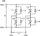
Dc source 101 outputs a predetermined dc voltage E give inverter 102.Inverter 102 carries out PWM (pulsewidth modulation) control by the Current Control part 109 of control appliance 105, and it adds to Linearkompressor 80 with the AC voltage e that dc voltage E converts above-mentioned resonant frequency to.As shown in figure 31, inverter 102 comprises four groups of gate turnoff thyristors and the feedback diode 111,115 that is connected into bridge circuit; 112,116; 113,117; 114,118.Lead-out terminal 102c and 102d are connected to the coil of the linear motor 86 of Linearkompressor 80 by current sensor 103.Voltage e between sub-102c in control output end and the 102d, making what flow to linear motor 86 coils is sine-wave current i.
Current sensor 103 detects the output current I of inverter 102, and testing result is added to the Current Control part 109 of control appliance 105.Position sensor 104 detects the position of Linearkompressor 80 pistons 82 directly or indirectly, and testing result is added to the current-order part 106 and the on/off operation part 107 of control appliance 105.Laser displacement gauge, linear velocity transducer, Hall unit etc. all can be used as position sensor 104.
The current-order part 106 of control appliance 105 is calculated current instruction value i according to the testing result of position sensor 104
s, and with calculated value add to the operation control section 108.Current-order part 106 is according to the Deviation Control current instruction value i between position sensor 104 detected positions and the target location
s
On/off operation part 107 is determined unlatching cycle of air bleeding valve 85 according to the testing result of position sensor 104, calculates on/off command value φ according to the result who determines.On/off command value φ is used as and sends the command signal of cutting off drive current i (electric current is disconnected) when air bleeding valve 85 is opened, and it supplies with the drive current i command signal of (electric current leads to) as sending when other cycles.
Operation control section 108 is in on/off operation part 107 is sent the cycle of on/off command value φ/cut-out electric current, send the instruction of cutting off electric current for Current Control part 109, and in the cycle of on/off command value φ instruction turn-on current, the instruction of sending turn-on current for Current Control part 109, and with current-order part 106 added current instruction value i
sAdd to Current Control part 109.
Current Control part 109 is cut off drive current i by the pulse output that stops inverter 102 during operation control section 108 sends the cut-out current-order.The pulse of Current Control part 109 control inverters 102 output makes position sensor 103 detected current i and current instruction value i thereby send at operation control section 108 between the turn-on current order period
sConsistent.
Figure 32 is a flow chart, represents the operation of driving arrangement shown in Figure 30.The operation of the driving arrangement of Linearkompressor 80 is now described briefly with reference to Figure 32.
DC power supply 101 adds to inverter 102 with dc voltage E, and inverter 102 adds to converter,linear 80 with drive current I, drives Linearkompressor 90 with this.
On step S121, each in current-order part 106 and the on/off operation part 107 is all passed through the position that position sensor 104 detects piston 82.On step S122, current-order part 106 is calculated current instruction value i according to the testing result of position sensor 104
s, on step S123, on/off operation part 106 is calculated on/off command value φ according to the testing result of position sensor 104.Current instruction value i
sAdd to operation control section 108 with on/off command value φ.
On step S124, operation control section 108 determines according to on/off command value φ whether electric current cuts off, if determine that electric current cuts off, then on step S125, sends the instruction of cutting off electric current to Current Control part 109.Do not cut off if on step S124, determine current i, the then instruction that operation control section 108 sends turn-on current to Current Control part 109 on step S126, and the current instruction value i from current-order part 106
sAdd to Current Control part 109.
On step S127, Current Control part 109 detects drive current i by current sensor 103, and on step S128, Current Control part 109 stops the pulse output of inverter 102 according to the instruction of cutting off electric current, and cut-out drive current i, and, go code according to electric current, the pulse output of control inverter 102 makes current sensor 108 detected current value i and current instruction value i
sConsistent.When current i was cut off, the electric power of supply was 0, therefore, 82 in piston be subjected to mechanical system equation of motion constraint and move.
On step S129, control appliance 105 determines whether control procedure is finished, if do not finish as yet, then step S121 is got back in control.
Figure 33 is an oscillogram, corresponding to Figure 29, and the pressure p in the speed v of expression piston 82, drive current i and the compression stroke 83.85 open period drive current i cut off at air bleeding valve, thus eliminated the phase place idle current different with speed v, so can obtain to be higher than the efficient of prior art.
In this embodiment, drive current i only cuts off at air bleeding valve 85 open periods.But, after current i can reach maximum in the speed of piston 82 until speed v reach 0 whole during cut off, in other words, piston 82 cuts off till it reaches top dead-centre after reaching neutral point.Perhaps, current i also can be lighted in any one time till air bleeding valve 85 is opened after speed v reaches maximum, reaches the cycle internal cutting off of 0 time point to speed v.Can open from air bleeding valve 85 after air bleeding valve 85 is closed soon a period of time, current i is set to cut off.Be preferably in efficient and current i cut off during near maximum, current i is easy to control.
[the tenth embodiment]
Figure 34 is a block diagram, and expression is according to the structure of the driving arrangement of the Linearkompressor 80 of tenth embodiment of the invention.In Figure 34, the driving arrangement of Linearkompressor 80 comprises AC power 121, switch 122, position sensor 123 and control appliance 124, and control appliance 124 comprises voltage instruction part 125, Control of Voltage part 126, on/off operation part 127 and switching control section 128.
The amplitude of AC power 121 is by Control of Voltage part 126 controls of control appliance 124, and it adds to the voltage e of above-mentioned resonant frequency the coil of the linear motor 136 of Linearkompressor 130 by switch 122.
The voltage instruction part 125 of control appliance 124 is according to the testing result calculating voltage command value e of position sensor 123
sAnd it is added to Control of Voltage part 126.Voltage instruction part 125 if the top dead-centre of piston 82 is lower than the precalculated position, then increases voltage instruction value e according to the top dead-centre of the testing result detection piston 82 of position sensor 123
s, and, then reduce voltage instruction value e if the top dead-centre of piston 82 is higher than the precalculated position
sControl of Voltage part 126 is according to voltage instruction part 125 added voltage instruction value e
sThe amplitude of control AC power 121 output voltages.
On/off operation part 127 is determined unlatching cycle of air bleeding valve 85 according to the testing result of position sensor 123, calculates on/off command value φ according to this result who determines, and it is added to switching control section 128.On/off command value φ is used as the command signal of cutting off electric current in air bleeding valve 85 open period orders, and is used as the command signal of order turn-on current in other times.Switching control section 128 makes switch 122 become non-conductive state in the added break-make command value of break-make operation part φ instructs the cycle that will cut off electric current, and makes switch 122 be in conduction state in other times.
Figure 35 is a flow chart, represents the operation of control appliance shown in Figure 34.The operation of the driving arrangement of linear compression face is now described briefly with reference to Figure 35.AC power 121 adds to Linearkompressor 80 with alternating voltage e by switch 122, so Linearkompressor 80 is driven.
On step S131, each in voltage instruction part 125 and the break-make operation part 127 is all passed through the position that position sensor 123 detects piston 82.On step S132, voltage instruction part 125 is according to the testing result calculating voltage command value e of position sensor 123
s, and on step S133, Control of Voltage part 126 is according to voltage instruction value e
sThe output voltage e of control AC power 121.
On step S134, break-make operation part 127 is calculated break-make command value φ, and it is added to switching control section 128.On step S135, switching control section 128 determines whether cut off electric current, if determine to cut off electric current, then sends the instruction that switch is disconnected at step S136, thereby makes switch be in non-conductive state.If determine not cut off electric current at step S135, then send the instruction that makes switch connection, thereby make switch be in conduction state at step S137.
In this embodiment and the 9th embodiment similar, also can eliminate the idle current i that has phase difference with the speed v of piston 82, thereby can obtain the efficient higher than prior art.
Although the present invention is described and at length illustrates,, obviously this just illustrates and example as an example, does not provide constraints, the spirit and scope of the present invention are limited by the clause of appended claim book only.
Claims (22)
1. its piston drives the driving arrangement that moves back and forth the Linearkompressor that produces Compressed Gas in cylinder by linear motor, it is characterized in that comprising:
Power supply (3), its output current is controlled, is used for driving described linear motor;
Position command device (31) is used for sending by SIN function the instruction of described piston position in the described cylinder;
Position detecting device (5) is used for detecting the position of described piston in described cylinder;
Speed instruction device (33) is used for the instruction that difference between the position that position and described position detecting device according to the instruction of described position command device detected sends described piston speed;
Speed detector (30) is used for detecting the speed of described piston;
Current-order device (35) is used for the instruction of sending output current to described power supply according to the difference between the speed of the speed of described speed instruction device instruction and the detection of described speed detector;
Current sensing means (4) is used for detecting the output current of described power supply;
Current control device (37) is used for controlling the output current of described power supply, and the electric current that described current sensing means is detected is consistent with the electric current of described current-order device instruction;
Phase difference detection device (38) is used for detecting the phase difference between the value of the described electric power outputting current that value and the expression of the speed of the described piston that expression detects by described speed detector instructed by described current-order device; And
Frequency adjusting device (38) is used for adjusting the frequency of the described SIN function that described position command device uses, to eliminate the phase difference that described phase difference detection device is detected.
2. according to the driving arrangement of the Linearkompressor of claim 1, it is characterized in that described speed detector (30) is by carrying out the speed that differential detects described piston to the testing result of described position detecting device (5).
3. according to the driving arrangement of the Linearkompressor of claim 1, it is characterized in that:
Difference between the position that described speed detector (33) is detected by position that described position command device (31) is instructed and described position detecting device (5) multiply by the speed value that first gain constant is calculated described piston, and instructs the speed of described piston according to this calculated value.
Described current-order device (35) multiply by the output current that second gain constant is calculated described power supply (3) by handle by the speed of described speed instruction device (33) instruction and by the difference between the speed of described speed detector (5) detection, and described power supply is sent the instruction of output current according to this calculated value;
The described driving arrangement of Linearkompressor also comprises:
Gain regulator (38), be used for adjusting at least one among used described second gain constant of first used gain constant of described speed instruction device and described current-order device, to eliminate the phase difference that described phase difference detection device (38) is detected.
4. according to the driving arrangement of the Linearkompressor of claim 1, it is characterized in that:
Described speed detector by will by the position of described position command device (31) instruction with multiply by first gain constant and the computational speed command value by the difference between the position of described position detecting device (5) detection, and the instruction of sending the speed of described piston according to this calculated value;
Described current-order device (35) multiply by the output current that second gain constant is calculated described power supply (3) by handle by speed instruction device (33) command speed and by the difference between the speed of described speed detector detection, and sends the instruction of described electric power outputting current according to this calculated value;
The described driving arrangement of Linearkompressor also comprises:
Peak difference checkout gear (45-47) is used for detecting by the peak value of position of piston described in the described cylinder of described position command device instruction and by the difference between the position peak value of described position detecting device detection; And
Gain regulator (48) is used for adjusting at least one among the second used gain constant of first used gain constant of described speed instruction device and described current-order device, to eliminate by the detected peak difference of described peak difference checkout gear.
5. according to the driving arrangement of the Linearkompressor of claim 4, it is characterized in that:
Described phase difference detection device (41-43) detect the described piston that detects by described speed detector speed zero crossing and by the zero crossing of the described electric power outputting current of described current-order device instruction, and detect described phase difference according to this testing result.
6. according to the driving arrangement of the Linearkompressor of claim 4, it is characterized in that: described phase difference detection device (51,52,43) detect the described piston that detects by described speed detector speed peak dot and by the peak dot of the described electric power outputting current of described current-order device instruction, and detect described phase difference according to this testing result.
7. according to the driving arrangement of the Linearkompressor of claim 1, it is characterized in that also comprising:
Amplitude adjustment apparatus (54) is used for as requested the compressed gas scale of construction to adjust the amplitude of the used described SIN function of described position command device.
8. according to the driving arrangement of the Linearkompressor of claim 7, it is characterized in that:
Described Compressed Gas is used for cooling object, and
The amount of the requirement of described Compressed Gas is expressed with the deviation between the temperature of described object and the predetermined target temperature.
9. according to the driving arrangement of the Linearkompressor of claim 1, it is characterized in that also comprising:
Active device (56), it responds the activation instruction of described Linearkompressor, adjusts the amplitude of the used described SIN function of described position command device and at least one among the frequency, makes the amplitude of described piston increase to predetermined target value gradually;
Described frequency adjusting device (38) is activated along with the finishing of activation of described Linearkompressor.
10. according to the driving arrangement of the Linearkompressor of claim 9, it is characterized in that:
Respond the halt instruction of described Linearkompressor and the described frequency adjusting device (38) of stopping using,
The described driving arrangement of Linearkompressor also comprises:
Arresting gear (56), it responds the halt instruction of described Linearkompressor and adjusts the amplitude of the used described SIN function of described position command device and at least one among the frequency, and the amplitude of described piston is reduced gradually.
11. its piston drives the driving arrangement that moves back and forth the Linearkompressor that produces Compressed Gas in cylinder by linear motor, it is characterized in that comprising:
Power supply (3) is used for according to current instruction value to described linear motor output driving current;
Position command device (60) is used for sending by SIN function the instruction of described piston position in the described cylinder;
Position detecting device (4,63) is used for detecting the position of described piston in described cylinder;
Current-order device (61,62) is used for producing described current instruction value and it is added to described power supply, makes the position that described position detecting device detects and the position consistency of described position command device instruction;
Speed detector (4,63) is used for detecting the speed of described piston in the described cylinder;
Phase difference detection device (65) is used for detecting by the current instruction value of described current-order device generation and by the phase difference between the speed of described speed detector detection; And
Frequency adjusting device (66,68), if surpass predetermined tolerance limit by the detected phase difference of described phase difference detection device, then be used for reducing the current instruction value that produces by the current-order device and be used among the amplitude of described SIN function of described position command device at least one to predetermined ratio, and control the frequency of described SIN function, to eliminate the phase difference that described phase difference detection device is detected.
12. its piston drives the driving arrangement that moves back and forth the Linearkompressor that produces Compressed Gas in cylinder by linear motor, it is characterized in that comprising:
Power supply (3) is used for according to current instruction value to described linear motor output driving current;
Current-order device (62,73) is used for applying described current instruction value according to the SIN function generation and to described power supply;
Amplitude detecting device (4,63,64) is used for detecting the amplitude of the described piston in the described cylinder;
Speed detector (4,63) is used for detecting the speed of described piston in the described cylinder;
Phase difference detection device (65) is used for detecting the phase difference between the speed that current instruction value and described speed detector detected that described current-order device produced;
Amplitude control unit (66) is used for controlling the amplitude of the used SIN function of described current-order device, and the amplitude that amplitude detecting device is detected is consistent with predetermined target value; And
Frequency control apparatus (66,68),, then be used for the amplitude of the described SIN function that the current-order device is used to be decreased to predetermined ratio if phase difference that described phase difference detection device detected surpasses predetermined tolerance limit, and control the frequency of described SIN function, to eliminate described phase difference.
13. its piston drives the driving arrangement that moves back and forth the Linearkompressor that produces Compressed Gas in cylinder by linear motor, it is characterized in that comprising:
Power supply (3) is used for according to current instruction value to described linear motor output driving current;
Position command device (60) is used for sending by SIN function the instruction of described piston position in the described cylinder;
Position detecting device (4,63) is used for detecting described position of piston in the described cylinder;
Amplitude detecting device (4,63) is used for testing result according to position detecting device, detects top dead-centre side amplitude between described piston top dead-centre and the initial point and the bottom dead centre side amplitude between bottom dead centre and the initial point;
Current-order device (61,62) is used for producing and applies described current instruction value to described power supply, the position consistency that position that described position detecting device detects and described position command device are instructed;
Amplitude control unit (61,66), be used for controlling at least one among the amplitude of the amplitude of the used SIN function of described position command device and the current instruction value that described current-order device is produced, make among top dead-centre side amplitude that described amplitude detecting device detects and the bottom dead centre side amplitude big person and predetermined target value consistent.
14. its piston drives the driving arrangement that moves back and forth the Linearkompressor that produces Compressed Gas in cylinder by linear motor, it is characterized in that comprising:
Power supply (3) is used for according to current instruction value to described linear motor output driving current;
Current-order device (62,73) is used for applying described current instruction value by the SIN function generation and to described power supply;
Position detecting device (4,63) is used for detecting described position of piston in the described cylinder;
Amplitude detecting device (64) is used for testing result according to position detecting device, detects top dead-centre side amplitude between described piston top dead-centre and the initial point and the bottom dead centre side amplitude between bottom dead centre and the initial point; And
Amplitude control unit (66) is used for controlling the amplitude of the used SIN function of described current-order device, makes top dead-centre side amplitude that described amplitude detecting device detects consistent with big person and predetermined target value among the bottom dead centre side amplitude.
15. its piston drives the driving arrangement that moves back and forth the Linearkompressor that produces Compressed Gas in cylinder by linear motor, it is characterized in that comprising:
Power supply (3) is used for according to current instruction value to described linear motor output driving current;
Position command device (60) is used for sending by SIN function the instruction of described piston position in the described cylinder;
Position detecting device (4,63) is used for detecting described position of piston in the described cylinder;
Current-order device (61,62) is used for producing and applies described current instruction value to described power supply, the position consistency that position that described position detecting device detects and described position command device are instructed;
Offset detector (64) is used for detecting the side-play amount that described piston neutral point leaves initial point according to the testing result of described position detecting device;
Side-play amount control device (67) is used for controlling the side-play amount of the used SIN function of described position command device, to eliminate the side-play amount that described offset detector is detected.
16. the driving arrangement according to the Linearkompressor of claim 15 is characterized in that also comprising:
Amplitude detecting device (64) is used for testing result according to position detecting device, detects top dead-centre side amplitude and the bottom dead centre of described piston and the bottom dead centre side amplitude between the initial point between described piston top dead-centre and the initial point; And
Amplitude control unit (66), be used for controlling at least one among the amplitude of the amplitude of the SIN function that is used for described position command device and the current instruction value that described current-order device is produced, make top dead-centre side amplitude that described amplitude detecting device detects consistent with big person and predetermined target value among the bottom dead centre side amplitude.
17. its piston drives the driving arrangement that moves back and forth the Linearkompressor that produces Compressed Gas in cylinder by linear motor, it is characterized in that comprising:
Power supply (3) is used for according to current instruction value to described linear motor output driving current;
Current-order device (62,73) is used for applying described current instruction value by the SIN function generation and to described power supply;
Position detecting device (4,63) is used for detecting described position of piston in the described cylinder;
Amplitude detecting device (64) is used for testing result according to described position detecting device, detects the amplitude of described piston;
Offset detector (64) is used for testing result according to described position detecting device, detects the side-play amount that described piston neutral point leaves initial point;
Amplitude control unit (66) is used for controlling the amplitude of the SIN function that is used for described current-order device, and the amplitude that described amplitude detecting device is detected is consistent with predetermined target value; And
Side-play amount control device (67) is used for controlling the side-play amount of the used SIN function of described current-order device, to eliminate the side-play amount that described offset detector is detected.
18. the driving arrangement according to the Linearkompressor of claim 17 is characterized in that:
Described amplitude detecting device (64) detects top dead-centre side amplitude and the bottom dead centre of described piston and the bottom dead centre side amplitude between the initial point between described piston top dead-centre and the initial point according to the testing result of described position detecting device; And
Described amplitude control unit (66) control is used for the amplitude of the SIN function of described current-order device, makes top dead-centre side amplitude that described amplitude detecting device detects consistent with big person and predetermined target value among the bottom dead centre side amplitude.
19. its piston drives the driving arrangement that moves back and forth and pass through the Linearkompressor of On/Off air bleeding valve and intake valve generation Compressed Gas by linear motor in cylinder, it is characterized in that comprising:
Power supply (101,102) is used for driving described linear motor;
Checkout gear (104,107) is used for detecting unlatching cycle of described air bleeding valve;
Current control device (108,109) is used for testing result according to described checkout gear, cuts off electric current from described power supply to described linear motor at one section preset time.
20. the driving arrangement according to the Linearkompressor of claim 19 is characterized in that:
The output current of described power supply can drive;
Described checkout gear comprises:
Position detecting device (104) is used for detecting described position of piston in the described cylinder;
Determine device (107), be used for testing result according to described position detecting device, determine the unlatching cycle of described air bleeding valve;
The described driving arrangement of Linearkompressor also comprises:
Current sensing means (103) is used for detecting the output current of described power supply; And
Current-order device (106) is used for testing result according to described position detecting device, the instruction of sending described electric power outputting current; Wherein
Described current control device cuts off one section preset time with the output current of described power supply, and control the output current of described power supply, make that the electric current that detects at other times, described current sensing means is consistent according to the electric current that definite result instructed of described definite device with described current-order device.
21. the driving arrangement according to the Linearkompressor of claim 19 is characterized in that:
The output current of described power supply is controlled;
Described checkout gear comprises:
Position detecting device (123) is used for detecting described position of piston in the described cylinder; And
Determine device (127), be used for testing result according to described position detecting device, determine the unlatching cycle of described air bleeding valve;
The described driving arrangement of Linearkompressor also comprises:
Current sensing means (103) is used for detecting the output current of described power supply; And
Voltage-operated device (125,126) is used for testing result according to described position detecting device, controls described electric power output voltage; And
Switching device (122), it is arranged between described power supply and the described linear motor; Wherein
It is non-conductive that described current control device (128) becomes described switching device in one section preset time, and make described switching device become conduction in other times according to definite result of described definite device.
22. the driving arrangement according to the Linearkompressor of claim 19 is characterized in that:
The unlatching cycle that described predetermined a period of time is described air bleeding valve.
Applications Claiming Priority (12)
| Application Number | Priority Date | Filing Date | Title |
|---|---|---|---|
| JP10004796A JP3177443B2 (en) | 1996-04-22 | 1996-04-22 | Drive unit for linear compressor |
| JP100047/96 | 1996-04-22 | ||
| JP08108908A JP3118413B2 (en) | 1996-04-30 | 1996-04-30 | Drive unit for linear compressor |
| JP108908/96 | 1996-04-30 | ||
| JP179493/96 | 1996-07-09 | ||
| JP17949396A JP3177448B2 (en) | 1996-07-09 | 1996-07-09 | Drive unit for linear compressor |
| JP268446/96 | 1996-10-09 | ||
| JP26844696A JP3177457B2 (en) | 1996-10-09 | 1996-10-09 | Drive unit for linear compressor |
| JP275940/96 | 1996-10-18 | ||
| JP27594196A JP3177460B2 (en) | 1996-10-18 | 1996-10-18 | Drive unit for linear compressor |
| JP27594096A JP3177459B2 (en) | 1996-10-18 | 1996-10-18 | Drive unit for linear compressor |
| JP275941/96 | 1996-10-18 |
Publications (1)
| Publication Number | Publication Date |
|---|---|
| CN1168965A true CN1168965A (en) | 1997-12-31 |
Family
ID=27552093
Family Applications (1)
| Application Number | Title | Priority Date | Filing Date |
|---|---|---|---|
| CN97109762A Pending CN1168965A (en) | 1996-04-22 | 1997-04-22 | Driving apparatus for linear compressor |
Country Status (3)
| Country | Link |
|---|---|
| US (1) | US5980211A (en) |
| KR (1) | KR100449128B1 (en) |
| CN (1) | CN1168965A (en) |
Cited By (8)
| Publication number | Priority date | Publication date | Assignee | Title |
|---|---|---|---|---|
| CN1313733C (en) * | 2000-11-29 | 2007-05-02 | Lg电子株式会社 | Apparatus and method for controlling operation of linear compressor |
| CN1325797C (en) * | 2000-11-29 | 2007-07-11 | Lg电子株式会社 | Equipment and method for controlling operation of linear compressor |
| CN100359175C (en) * | 1999-11-30 | 2008-01-02 | 松下电器产业株式会社 | Linear compressor driving device, medium and information assembly |
| CN1930764B (en) * | 2004-03-05 | 2010-05-05 | Bsh博世和西门子家用器具有限公司 | Device for adjusting the armature stroke in a reversible linear drive unit |
| CN101835980B (en) * | 2007-10-24 | 2012-07-04 | Lg电子株式会社 | Reciprocating compressor |
| CN104728074A (en) * | 2013-12-19 | 2015-06-24 | Lg电子株式会社 | Device and method for controlling linear compressor |
| CN106605061A (en) * | 2014-08-25 | 2017-04-26 | Lg电子株式会社 | Linear compressor, and apparatus and method for controlling linear compressor |
| CN109026633A (en) * | 2018-09-30 | 2018-12-18 | 海南汉地阳光石油化工有限公司 | A kind of compressor air-discharging quantity regulating device |
Families Citing this family (70)
| Publication number | Priority date | Publication date | Assignee | Title |
|---|---|---|---|---|
| US6121736A (en) * | 1998-07-10 | 2000-09-19 | Matsushita Electric Industrial Co., Ltd. | Control apparatus for motor, and motor unit having the control apparatus |
| DE19952578B4 (en) * | 1998-11-04 | 2005-11-24 | Lg Electronics Inc. | Apparatus and method for controlling a linear compressor |
| US6129527A (en) * | 1999-04-16 | 2000-10-10 | Litton Systems, Inc. | Electrically operated linear motor with integrated flexure spring and circuit for use in reciprocating compressor |
| KR100526006B1 (en) * | 1999-06-21 | 2005-11-08 | 피셔 앤 페이켈 어플라이언스 리미티드 | Linear motor |
| US6264432B1 (en) * | 1999-09-01 | 2001-07-24 | Liquid Metronics Incorporated | Method and apparatus for controlling a pump |
| KR100317301B1 (en) * | 2000-01-21 | 2001-12-22 | 구자홍 | apparatus and method for sensing position of piston in linear compressor |
| DE10033992A1 (en) * | 2000-07-12 | 2002-01-31 | Grundfos As | Conveyor device with a current-controlled motor |
| US6520746B2 (en) * | 2000-09-27 | 2003-02-18 | Lg Electronics Inc. | Apparatus and method for controlling operation of reciprocating compressor |
| KR100378815B1 (en) * | 2000-11-28 | 2003-04-07 | 엘지전자 주식회사 | Stroke shaking detection apparatus and method for linear compressor |
| KR100367605B1 (en) * | 2000-11-29 | 2003-01-14 | 엘지전자 주식회사 | Driving control apparatus for linear compressor using pattern recognition |
| BRPI0105524B1 (en) * | 2000-11-29 | 2015-08-18 | Lg Electronics Inc | Linear Compressor Control Apparatus and Method |
| KR100397556B1 (en) * | 2001-03-23 | 2003-09-17 | 주식회사 엘지이아이 | Reciprocating compressor |
| JP2002285958A (en) * | 2001-03-28 | 2002-10-03 | Matsushita Refrig Co Ltd | Control valve of linear compressor |
| US6494685B2 (en) * | 2001-03-29 | 2002-12-17 | Kadant, Inc. | Pump and motor assembly with constant pressure output |
| US6623246B2 (en) * | 2001-04-13 | 2003-09-23 | Lg Electronics Inc. | Apparatus and method for controlling operation of linear motor compressor |
| JP3511018B2 (en) * | 2001-05-18 | 2004-03-29 | 松下電器産業株式会社 | Linear compressor drive |
| KR100408068B1 (en) * | 2001-07-31 | 2003-12-03 | 엘지전자 주식회사 | Stroke comtrol apparatus for reciprocating compressor |
| US6685438B2 (en) * | 2001-08-01 | 2004-02-03 | Lg Electronics Inc. | Apparatus and method for controlling operation of reciprocating compressor |
| US6682310B2 (en) * | 2001-08-01 | 2004-01-27 | Lg Electronics Inc. | Apparatus and method for controlling operation of reciprocating motor compressor |
| KR100411786B1 (en) * | 2001-09-03 | 2003-12-24 | 삼성전자주식회사 | Apparatus and method for controlling linear compressor |
| NZ515578A (en) * | 2001-11-20 | 2004-03-26 | Fisher & Paykel Appliances Ltd | Reduction of power to free piston linear motor to reduce piston overshoot |
| US6595757B2 (en) * | 2001-11-27 | 2003-07-22 | Kuei-Hsien Shen | Air compressor control system |
| JP2003220363A (en) * | 2002-01-29 | 2003-08-05 | Citizen Electronics Co Ltd | Axially driven vibration body |
| KR100471719B1 (en) * | 2002-02-28 | 2005-03-08 | 삼성전자주식회사 | Controlling method of linear copressor |
| KR20030079784A (en) * | 2002-04-04 | 2003-10-10 | 마츠시타 덴끼 산교 가부시키가이샤 | Refrigerating cycle apparatus |
| US20040028550A1 (en) * | 2002-04-10 | 2004-02-12 | Thomas Robert Malcolm | Air purification with ozone |
| US6885116B2 (en) * | 2002-05-06 | 2005-04-26 | Jeffrey G. Knirck | Moving coil linear motor positioning stage with a concentric aperture |
| BR0300010B1 (en) * | 2003-01-08 | 2012-05-02 | Linear compressor control system, Linear compressor control method, Linear compressor and refrigeration system. | |
| DE10314007A1 (en) * | 2003-03-28 | 2004-10-07 | Leybold Vakuum Gmbh | Piston vacuum pump for pumping gas, has sensor that detects speed of switching supply of energizing current between electrical coils by magnet arrangement |
| KR100941422B1 (en) * | 2003-08-04 | 2010-02-10 | 삼성전자주식회사 | Linear compressor and control apparatus thereof |
| NZ527999A (en) * | 2003-09-02 | 2005-08-26 | Fisher & Paykel Appliances Ltd | Controller improvements |
| WO2005045248A1 (en) * | 2003-11-11 | 2005-05-19 | Lg Electronics Inc. | Driving controlling appratus of linear compressor and method thereof |
| BRPI0400108B1 (en) | 2004-01-22 | 2017-03-28 | Empresa Brasileira De Compressores S A - Embraco | linear compressor and control method of a linear compressor |
| KR100533041B1 (en) * | 2004-02-20 | 2005-12-05 | 엘지전자 주식회사 | Driving control apparatus and method for reciprocating compressor |
| DE102004010403A1 (en) * | 2004-03-03 | 2005-09-22 | BSH Bosch und Siemens Hausgeräte GmbH | Reversing linear drive with means for detecting an anchor position |
| US7032400B2 (en) | 2004-03-29 | 2006-04-25 | Hussmann Corporation | Refrigeration unit having a linear compressor |
| DE112004002959T5 (en) * | 2004-08-30 | 2007-06-28 | Lg Electronics Inc. | Apparatus and method for controlling a linear compressor |
| CN101305512B (en) * | 2004-08-30 | 2012-03-28 | Lg电子株式会社 | Straight-line compressor |
| KR100899057B1 (en) * | 2004-11-01 | 2009-05-25 | 미쓰비시덴키 가부시키가이샤 | Voice coil motor control device, drive method for the device, and image pickup device |
| US7213405B2 (en) * | 2005-05-10 | 2007-05-08 | Hussmann Corporation | Two-stage linear compressor |
| US7478539B2 (en) * | 2005-06-24 | 2009-01-20 | Hussmann Corporation | Two-stage linear compressor |
| US7628027B2 (en) * | 2005-07-19 | 2009-12-08 | Hussmann Corporation | Refrigeration system with mechanical subcooling |
| KR100690690B1 (en) * | 2005-11-01 | 2007-03-09 | 엘지전자 주식회사 | Apparatus for controlling operation of reciprocating compressor and method thereof |
| KR100774470B1 (en) * | 2006-01-16 | 2007-11-08 | 엘지전자 주식회사 | Driving control apparatus and method for reciprocating compressor |
| US8079825B2 (en) * | 2006-02-21 | 2011-12-20 | International Rectifier Corporation | Sensor-less control method for linear compressors |
| DE102006009256A1 (en) * | 2006-02-28 | 2007-08-30 | BSH Bosch und Siemens Hausgeräte GmbH | Compressor apparatus for household cooling equipment e.g. refrigerator, freezer has linear drive having adjustable rotor zero position, and linear compressor having adjustable piston zero position |
| DE102006009259A1 (en) * | 2006-02-28 | 2007-08-30 | BSH Bosch und Siemens Hausgeräte GmbH | Closed-loop control method for linear drive e.g. linear compressor, involves moving linear drive to and fro along drive axis, where linear drive has stator, rotor and drive coil through which coil current flows |
| KR100870541B1 (en) * | 2007-03-30 | 2008-11-26 | 엘지전자 주식회사 | Refrigerator and the controlling method |
| JP5091535B2 (en) * | 2007-04-26 | 2012-12-05 | 三洋電機株式会社 | Motor control device |
| BRPI0902557B1 (en) * | 2009-07-08 | 2020-03-10 | Embraco Indústria De Compressores E Soluções E Refrigeração Ltda. | LINEAR COMPRESSOR |
| DE102009038308A1 (en) * | 2009-08-21 | 2011-02-24 | Siemens Aktiengesellschaft | Method for operating a refrigeration device for cooling a superconductor and cooling device suitable for this purpose |
| KR101665695B1 (en) * | 2009-11-18 | 2016-10-13 | 엘지전자 주식회사 | Linear compressor |
| US9217429B2 (en) | 2009-11-18 | 2015-12-22 | Lg Electronics Inc. | Linear compressor |
| BRPI1101094A2 (en) | 2011-03-15 | 2013-06-11 | Whirlpool Sa | resonant linear compressor drive system, resonant linear compressor drive method and resonant linear compressor |
| CN102392813B (en) * | 2011-06-10 | 2015-10-14 | 辽宁华兴森威科技发展有限公司 | Compressor unit speed adjustment control system |
| BRPI1103355A2 (en) * | 2011-07-04 | 2013-07-23 | Whirlpool Sa | adapter device for linear compressor, and compressor provided with said device |
| BRPI1103314A2 (en) * | 2011-07-21 | 2013-08-06 | Whirlpool Sa | linear compressor |
| BRPI1103776B1 (en) | 2011-08-19 | 2018-12-04 | Whirlpool Sa | system and method of stroke control and resonant frequency operation of a resonant linear motor |
| US8723462B2 (en) * | 2012-06-15 | 2014-05-13 | GM Global Technology Operations LLC | Methods, systems and apparatus for estimating angular position and/or angular velocity of a rotor of an electric machine |
| US8937411B2 (en) * | 2012-09-06 | 2015-01-20 | Samsung Electro-Mechanics Co., Ltd. | Vibration generating device |
| US10502201B2 (en) | 2015-01-28 | 2019-12-10 | Haier Us Appliance Solutions, Inc. | Method for operating a linear compressor |
| US10208741B2 (en) | 2015-01-28 | 2019-02-19 | Haier Us Appliance Solutions, Inc. | Method for operating a linear compressor |
| BR102015016317B1 (en) * | 2015-07-07 | 2022-07-19 | Embraco Indústria De Compressores E Soluções Em Refrigeração Ltda | METHOD AND PROTECTION SYSTEM OF A RESONANT LINEAR COMPRESSOR |
| US10174753B2 (en) * | 2015-11-04 | 2019-01-08 | Haier Us Appliance Solutions, Inc. | Method for operating a linear compressor |
| JP6591668B2 (en) * | 2016-05-27 | 2019-10-16 | 株式会社日立製作所 | Linear motor system and compressor |
| JP6749205B2 (en) * | 2016-10-13 | 2020-09-02 | 日立グローバルライフソリューションズ株式会社 | Linear motor control device and compressor equipped with the same |
| US10830230B2 (en) | 2017-01-04 | 2020-11-10 | Haier Us Appliance Solutions, Inc. | Method for operating a linear compressor |
| KR102237724B1 (en) * | 2017-03-27 | 2021-04-08 | 엘지전자 주식회사 | Linear compressor and method for controlling linear compressor |
| US10641263B2 (en) | 2017-08-31 | 2020-05-05 | Haier Us Appliance Solutions, Inc. | Method for operating a linear compressor |
| US10670008B2 (en) | 2017-08-31 | 2020-06-02 | Haier Us Appliance Solutions, Inc. | Method for detecting head crashing in a linear compressor |
Family Cites Families (13)
| Publication number | Priority date | Publication date | Assignee | Title |
|---|---|---|---|---|
| US3937600A (en) * | 1974-05-08 | 1976-02-10 | Mechanical Technology Incorporated | Controlled stroke electrodynamic linear compressor |
| US3980964A (en) * | 1974-05-20 | 1976-09-14 | Grodinsky Robert M | Noise reduction circuit |
| US3947155A (en) * | 1974-09-19 | 1976-03-30 | Tecumseh Products Company | Linear compressor |
| JPS5284507A (en) * | 1975-12-30 | 1977-07-14 | Mekanikaru Tekunorojii Inc | Linear compressors |
| US4353220A (en) * | 1980-06-17 | 1982-10-12 | Mechanical Technology Incorporated | Resonant piston compressor having improved stroke control for load-following electric heat pumps and the like |
| US4291258A (en) * | 1980-06-17 | 1981-09-22 | Mechanical Technology Incorporated | DC Excitation control for linear oscillating motors |
| US4490691A (en) * | 1980-06-30 | 1984-12-25 | Dolby Ray Milton | Compressor-expander circuits and, circuit arrangements for modifying dynamic range, for suppressing mid-frequency modulation effects and for reducing media overload |
| US4498055A (en) * | 1981-09-10 | 1985-02-05 | Dolby Ray Milton | Circuit arrangements for modifying dynamic range |
| US4498060A (en) * | 1981-12-01 | 1985-02-05 | Dolby Ray Milton | Circuit arrangements for modifying dynamic range using series arranged bi-linear circuits |
| US4736433A (en) * | 1985-06-17 | 1988-04-05 | Dolby Ray Milton | Circuit arrangements for modifying dynamic range using action substitution and superposition techniques |
| US4750871A (en) * | 1987-03-10 | 1988-06-14 | Mechanical Technology Incorporated | Stabilizing means for free piston-type linear resonant reciprocating machines |
| JPH02154950A (en) * | 1988-12-08 | 1990-06-14 | Fujitsu Ltd | Stirling refrigerator |
| US5535593A (en) * | 1994-08-22 | 1996-07-16 | Hughes Electronics | Apparatus and method for temperature control of a cryocooler by adjusting the compressor piston stroke amplitude |
-
1997
- 1997-04-18 US US08/840,463 patent/US5980211A/en not_active Expired - Fee Related
- 1997-04-21 KR KR1019970014796A patent/KR100449128B1/en not_active IP Right Cessation
- 1997-04-22 CN CN97109762A patent/CN1168965A/en active Pending
Cited By (12)
| Publication number | Priority date | Publication date | Assignee | Title |
|---|---|---|---|---|
| CN100359175C (en) * | 1999-11-30 | 2008-01-02 | 松下电器产业株式会社 | Linear compressor driving device, medium and information assembly |
| CN1313733C (en) * | 2000-11-29 | 2007-05-02 | Lg电子株式会社 | Apparatus and method for controlling operation of linear compressor |
| CN1325797C (en) * | 2000-11-29 | 2007-07-11 | Lg电子株式会社 | Equipment and method for controlling operation of linear compressor |
| CN1930764B (en) * | 2004-03-05 | 2010-05-05 | Bsh博世和西门子家用器具有限公司 | Device for adjusting the armature stroke in a reversible linear drive unit |
| CN101835980B (en) * | 2007-10-24 | 2012-07-04 | Lg电子株式会社 | Reciprocating compressor |
| CN104728074A (en) * | 2013-12-19 | 2015-06-24 | Lg电子株式会社 | Device and method for controlling linear compressor |
| CN104728074B (en) * | 2013-12-19 | 2017-04-12 | Lg电子株式会社 | Device and method for controlling linear compressor |
| US9850890B2 (en) | 2013-12-19 | 2017-12-26 | Lg Electronics Inc. | Device and method for controlling linear compressor |
| CN106605061A (en) * | 2014-08-25 | 2017-04-26 | Lg电子株式会社 | Linear compressor, and apparatus and method for controlling linear compressor |
| CN106605061B (en) * | 2014-08-25 | 2019-12-27 | Lg电子株式会社 | Linear compressor and apparatus and method for controlling the same |
| US10598175B2 (en) | 2014-08-25 | 2020-03-24 | Lg Electronics Inc. | Linear compressor, and apparatus and method for controlling a linear compressor |
| CN109026633A (en) * | 2018-09-30 | 2018-12-18 | 海南汉地阳光石油化工有限公司 | A kind of compressor air-discharging quantity regulating device |
Also Published As
| Publication number | Publication date |
|---|---|
| KR100449128B1 (en) | 2004-12-03 |
| KR970070561A (en) | 1997-11-07 |
| US5980211A (en) | 1999-11-09 |
Similar Documents
| Publication | Publication Date | Title |
|---|---|---|
| CN1168965A (en) | Driving apparatus for linear compressor | |
| CN1128293C (en) | Oscillation-type compressor | |
| CN1083939C (en) | Linear compressor | |
| CN1248073C (en) | Position controller for motor | |
| CN1261689C (en) | Method for controlling linear compressor | |
| CN1516918A (en) | Synchronuos reluctance motor control device | |
| CN1278483C (en) | Motor control device | |
| CN1066831C (en) | Controller | |
| CN1302610C (en) | DC-DC converter | |
| CN1241320C (en) | Control method and control device of brushless motor | |
| CN1287976C (en) | Pressing machine | |
| CN1134885C (en) | High-frequency inverter and induction cooking device using the same | |
| CN1063381A (en) | Voltage or powerless control method and control appliance thereof | |
| CN1545758A (en) | Control system for a linear vibration motor | |
| CN1263377A (en) | Power supply device and air conditioner using said power supply | |
| CN1477767A (en) | Electric motor driving controller | |
| CN1671964A (en) | Compressor internal state estimating device and air conditioner | |
| CN1482727A (en) | D.C.-D.C. converter | |
| CN1750376A (en) | Switching power supply circuit | |
| CN1704718A (en) | Surface scan measuring device, surface scan measuring method, surface scan measuring program and recording medium | |
| CN1543057A (en) | Inverter controller for driving motor and air conditioner using the same | |
| CN1794893A (en) | Discharge lamp lighting device and lighting system | |
| CN1858981A (en) | Power supply regulator circuit and semiconductor device | |
| CN1961475A (en) | Ac motor decelerating method and inverter device | |
| CN1961612A (en) | High-frequency heating device |
Legal Events
| Date | Code | Title | Description |
|---|---|---|---|
| C06 | Publication | ||
| PB01 | Publication | ||
| C10 | Entry into substantive examination | ||
| SE01 | Entry into force of request for substantive examination | ||
| C02 | Deemed withdrawal of patent application after publication (patent law 2001) | ||
| WD01 | Invention patent application deemed withdrawn after publication |