CN1168415C - Electric cleaner - Google Patents
Electric cleaner Download PDFInfo
- Publication number
- CN1168415C CN1168415C CNB011171383A CN01117138A CN1168415C CN 1168415 C CN1168415 C CN 1168415C CN B011171383 A CNB011171383 A CN B011171383A CN 01117138 A CN01117138 A CN 01117138A CN 1168415 C CN1168415 C CN 1168415C
- Authority
- CN
- China
- Prior art keywords
- exhaust
- hose
- dust collector
- mentioned
- connector
- Prior art date
- Legal status (The legal status is an assumption and is not a legal conclusion. Google has not performed a legal analysis and makes no representation as to the accuracy of the status listed.)
- Expired - Fee Related
Links
Images


Classifications
-
- A—HUMAN NECESSITIES
- A47—FURNITURE; DOMESTIC ARTICLES OR APPLIANCES; COFFEE MILLS; SPICE MILLS; SUCTION CLEANERS IN GENERAL
- A47L—DOMESTIC WASHING OR CLEANING; SUCTION CLEANERS IN GENERAL
- A47L7/00—Suction cleaners adapted for additional purposes; Tables with suction openings for cleaning purposes; Containers for cleaning articles by suction; Suction cleaners adapted to cleaning of brushes; Suction cleaners adapted to taking-up liquids
- A47L7/04—Suction cleaners adapted for additional purposes; Tables with suction openings for cleaning purposes; Containers for cleaning articles by suction; Suction cleaners adapted to cleaning of brushes; Suction cleaners adapted to taking-up liquids for using the exhaust air for other purposes, e.g. for distribution of chemicals in a room, for sterilisation of the air
-
- A—HUMAN NECESSITIES
- A47—FURNITURE; DOMESTIC ARTICLES OR APPLIANCES; COFFEE MILLS; SPICE MILLS; SUCTION CLEANERS IN GENERAL
- A47L—DOMESTIC WASHING OR CLEANING; SUCTION CLEANERS IN GENERAL
- A47L5/00—Structural features of suction cleaners
- A47L5/12—Structural features of suction cleaners with power-driven air-pumps or air-compressors, e.g. driven by motor vehicle engine vacuum
- A47L5/22—Structural features of suction cleaners with power-driven air-pumps or air-compressors, e.g. driven by motor vehicle engine vacuum with rotary fans
- A47L5/36—Suction cleaners with hose between nozzle and casing; Suction cleaners for fixing on staircases; Suction cleaners for carrying on the back
- A47L5/362—Suction cleaners with hose between nozzle and casing; Suction cleaners for fixing on staircases; Suction cleaners for carrying on the back of the horizontal type, e.g. canister or sledge type
-
- A—HUMAN NECESSITIES
- A47—FURNITURE; DOMESTIC ARTICLES OR APPLIANCES; COFFEE MILLS; SPICE MILLS; SUCTION CLEANERS IN GENERAL
- A47L—DOMESTIC WASHING OR CLEANING; SUCTION CLEANERS IN GENERAL
- A47L9/00—Details or accessories of suction cleaners, e.g. mechanical means for controlling the suction or for effecting pulsating action; Storing devices specially adapted to suction cleaners or parts thereof; Carrying-vehicles specially adapted for suction cleaners
- A47L9/0081—Means for exhaust-air diffusion; Means for sound or vibration damping
Landscapes
- Engineering & Computer Science (AREA)
- Mechanical Engineering (AREA)
- Electric Suction Cleaners (AREA)
- Electric Vacuum Cleaner (AREA)
Abstract
The invention provides a vacuum cleaner allowing a user's discomfort from exhaust to be eliminated by lowering the temperature of the exhaust and abating noise and bringing about the improvement of the floating structure, using the exhaust, of a vacuum cleaner body and a connecting body for connecting the vacuum cleaner body and a suction implement for a floor together. The vacuum cleaner is provided with the vacuum cleaner body 1 housing a dust collecting part 8 and a motor fan 16, the suction implement for the floor, whereby dust is captured, a connecting body 6 composed of a connecting pipe, a hose member 5, etc., in order to draw in the dust captured by the suction implement with outdoor air to the collecting part 8 by suction, an exhaust passage 25 installed in the connecting body 6 so as to guide the exhaust from the motor fan 16, and a communicating passage 19 installed in the cleaner body 1 so as to guide the exhaust into the exhaust passage 25, which is formed with a plurality of exhaust ports 27 communicating with the inside and the outside.
Description
Technical field
The present invention relates to electric dust collector, more particularly, relate to the low temperatureization of the air themperature that is loaded on the intrinsic electric blowing machine discharge of electric dust collector in can realizing certainly, and can reduce the low temperature structure and the noise-reducing structure of a kind of like this electric dust collector of noise of electric blowing machine generation.
In addition, the invention still further relates to the come-up structure of electric dust collector body and the connector that connects floor suction head and electric dust collector body.
Background technology
As having an example of electric dust collector that the electric blowing machine noise is carried out the noise-reducing structure of noise reduction, there has been the spy to open the disclosed invention of flat 3-55020 communique, Figure 12 illustrates the cutaway view of the major part of this electric dust collector.
Among the figure, the 50th, the bottom surface has moves the body that the electric dust collector of electric blowing machine 52 etc. is housed with wheel 51, inside, the close exhaust outlet 53 in back be provided with have can free folding spring or the fenestra 54 of slidingtype blade 55.The 57th, the exhaust flow path that is provided with fenestra 54 position in opposite directions on the next door 56, inner edge is equipped with the rubber 58 of sealing usefulness.
59 be that an end inserts in the exhaust flow path 57, the outlet 60 of the other end the following face forward opening of body 50, can rotate freely and detachable ground is installed, section roughly is the hush pipe of " コ " font, at bend inner surface and outlet 60 places quieter material 61 is installed.Arrow is represented the flow direction from the exhaust of electric blowing machine 52.
As above the electric dust collector of Gou Chenging comes from the air of electric blowing machine 52 and all discharges outside body 50 by hush pipe 59 when work.At this moment, because hush pipe 59 is longer to the distance of outlet 60, and inside is provided with quieter material 61, and therefore, the high speed exhaust airstream slowly slows down under the effect of the noise reduction effect of hush pipe 59, also can reduce exhaust noise.In addition, because the outlet 60 that is positioned at below the body 50 is far away to user's distance in one's ear, simultaneously, body 50 also plays deadening, therefore, can increase the effect of noise reduction.
Aforesaid existing electric dust collector since hush pipe 59 is long and outlet 60 be positioned at body 50 below, therefore, can reduce exhaust noise from electric blowing machine 52.But the air that the bigger electric blowing machine of power 52 is discharged not only can produce noise, and temperature is also higher, particularly, in the higher occasion of indoor air temperatures such as summer, when exhaust is blown on the skin the user, can give uncomfortable feeling.And recently, along with the high-power of electric blowing machine 52, power consumption arrives the degree of 1kW greatly, so delivery temperature is also higher, and delivery temperature is growing on and on to the uncomfortable feeling that the user causes.
In addition, in order to reduce the noise of exhaust, hush pipe 59 is done longlyer, and because hush pipe 59 is to be provided with from the outside outstanding state of back one side direction of body 50, therefore, to cause the electric dust collector overall volume bigger, and the operation that hush pipe 59 is installed is also pretty troublesome.In addition, the outlet 60 of hush pipe 59 be positioned at body 50 following, promptly near on the position on ground, therefore, can kick up floor-dust from the air that outlet 60 is discharged.
The present invention is intended to solve above-mentioned existing problems, its objective is that providing a kind of realizes the low temperatureization of electric blowing machine delivery temperature and can reduce exhaust noise, avoid the user to produce uncomfortable sensation, simultaneously, can prevent that exhaust from kicking up dust and electric dust collector that cleaning performance is improved.
In addition, the purpose of this invention is to provide a kind of to the connector that utilizes exhaust to realize the come-up structure of electric dust collector body come-up and floor suction head is connected with the electric dust collector body improved electric dust collector in addition.
Summary of the invention
Electric dust collector involved in the present invention has: inside is provided with dedusting portion, electric blowing machine, with the body of dust collector of guiding from the access of the exhaust of this electric blowing machine, floor suction head with the dust suction, one end is connected on the floor suction head, the other end releasably is connected the tube connector on the handle, have the sweep-up pipe that is communicated with dedusting portion in inside and be formed on the periphery of this sweep-up pipe, the exhaust channel that is communicated with above-mentioned access, be used for removably being connected the connector on the above-mentioned body of dust collector, one end is fixed on the handle, the other end is fixed on the connector, the inhaling hose that is communicated with above-mentioned sweep-up pipe, it is characterized in that, comprise: be arranged on the chimeric fixed part on the above-mentioned handle, and one end have fitting portion on the chimeric fixed part that is used for releasably being connected above-mentioned handle, the other end and above-mentioned exhaust channel are fixed on the above-mentioned connector communicatively, above-mentioned inhaling hose is housed in inside, between itself and inhaling hose, form the exhaust hose of heat exchange paths, on above-mentioned exhaust hose, with on the position of cleaning ground subtend be not provided with the exhaust from electric blowing machine be discharged to indoor a plurality of exhaust outlets by above-mentioned heat exchange paths.
Electric dust collector involved in the present invention is that inhaling hose has can be in the structure of shrinking on its long axis direction under the suction function of electric blowing machine.
In addition, exhaust hose has the structure that can freely stretch under external force on its long axis direction.
Electric dust collector involved in the present invention is that air-breathing exhaust hose has the structure that can be housed in the exhaust hose when it shrinks.
Electric dust collector involved in the present invention is to be located on the pipe of connection to the exhaust outlet of indoor discharge from the exhaust of electric blowing machine.
In addition, indoor suspension is located on the tube connector with the outer aspiration inlet that outer gas sucks, can will goes into dedusting portion by the above-mentioned outer aspiration that this outer aspiration inlet sucks by floor suction head at least.
In addition, technical scheme 3 related inventions are that exhaust hose has the structure that can freely stretch under external force on its long axis direction,
And then, technical scheme 4 related inventions are that inhaling hose has the structure that can be housed in the exhaust hose when it shrinks, therefore, can change the length of heat exchange paths arbitrarily, and when making inhaling hose be contracted in the exhaust hose as required, body of dust collector becomes compact and is convenient to keeping and collection.
Description of drawings
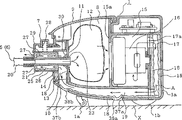
Fig. 1 is the longitudinal sectional view and the operation principle key diagram thereof of the related body of dust collector of the invention process form 1.
Fig. 2 is the amplification view and the operation principle key diagram thereof of the major part of Fig. 1.
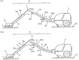
Fig. 3 is the schematic diagram of the user mode of the invention process form 1.
Fig. 4 is the amplification view and the operation principle key diagram of the major part of the invention process form 2.
Fig. 5 is the longitudinal sectional view and the operation principle key diagram thereof of the related body of dust collector of the invention process form 3.
Fig. 6 is the longitudinal sectional view and the operation principle key diagram thereof of the related body of dust collector of the invention process form 4.
Fig. 7 is longitudinal sectional view and the operation principle key diagram thereof with body of dust collector of the related come-up parts of form of implementation 4.
Fig. 8 is the longitudinal sectional view and the operation principle key diagram thereof of body of dust collector of come-up parts with other example of form of implementation 4.
Fig. 9 is the key diagram and the operation principle key diagram thereof of the related electric dust collector of the invention process form 5.
Figure 10 is the key diagram and the operation principle key diagram thereof of the related electric dust collector of the invention process form 6.
Figure 11 is the key diagram and the operation principle key diagram thereof of the related electric dust collector of the invention process form 7.
Figure 12 is the cutaway view of existing electric dust collector major part.
The specific embodiment
Form of implementation 1
Fig. 1 is the longitudinal sectional view of the related body of dust collector of the invention process form 1, and Fig. 2 is the amplification view of its major part, and Fig. 3 is the schematic diagram of the user mode of the invention process form 1.
Among the figure, the 1st, the body of electric dust collector, floor suction head 2 is attached thereto by connector 6.This connector 6 is linked the tube connector 3 that floor suction head 2 is arranged by an end, the other end of one end by handle 4 and tube connector 3 links and hose 5 formations that the other end and body 1 link, and the latch hook 7 detachable ground of the other end of connector 6 by being arranged on hose 5 are installed.
Among Fig. 1, the 8th, be formed at the dirt pocket of the place ahead one side in the body 1, top is provided with the open-close lid 9 that the top, front of body 1 can be opened.The 13rd, be formed at the exhaust cup in the place ahead of dirt pocket 8 in the body 1, be provided with in its front that the other end for the hose 5 of connector 6 inserts and its flexible pipe of supporting is inserted mouthfuls 14, be provided with the peristome 10 that is communicated with dirt pocket 8 in the back.In addition, the cardboard 11 that is made of ground paper is installed on peristome 10 detachable, this cardboard 11 have be contained in the dirt pocket 8, the dust removing body such as dust settling pocket 12 with gas permeability, by cardboard 11 with peristome 10 sealing, and with dirt pocket 8 and exhaust cup 13 the two is separated.Dust removing body 12 also can be to utilize cyclone dust collectors that centrifugal separator etc. removes dust etc., and its mode is not particularly limited.In addition, locate to be equipped with quieter material 18 in the gap of the front of exhaust cup 13 etc.
The 15th, be formed at the motor room of rear one side in the body 1 by being located at partition wall 15a in the body 1 with passage, contain electric blowing machine 16.The 17th, be formed at chamber after the exhaust at 15 rears, body built-in motor chamber 1, be provided with the intercommunicating pore 17a that is communicated with motor room 15 in its front, quieter material 18 is installed on the inner surface.19 are provided in a side of the access of the bottom in the body 1, and an end is communicated with chamber 17 after the exhaust, and the other end is communicated with exhaust cup 13, and quieter material 18 is installed on the inner surface of its underpart.1a is a front vehicle wheel, and 1b is a pair of rear wheel, and the two 1a, 1b are installed in the bottom of body 1.
The hose 5 of connector 6 as shown in Figure 3, but by the inhaling hose that soft material constituted 20 of free bend, be located at the handle 4 on the one end and the connector 21 that is located on the other end constitutes.As depicted in figs. 1 and 2, this connector 21 is made of sweep-up pipe 23, blast pipe 26 and sticking department 29, wherein, said sweep-up pipe 23 embeds and is fixed with the end of inhaling hose 20 at the flexible pipe air entry 22a place of one end, the flexible pipe exhaust outlet 22b of the other end runs through cardboard 11 and inserts in the dust removing body 12; Said blast pipe 26 is positioned at the part of exhaust cup 13 when being formed into when connector 21 being plugged on flexible pipe insertion mouth 14 always near the end that is fixed with inhaling hose 20 of the peripheral part of sweep-up pipe 23 till, have the exhaust entrance 24 that is communicated with exhaust cup 13 in the end of exhaust cup 13 1 sides, and be formed with exhaust channel 25 between the periphery wall of sweep-up pipe 23; Said sticking department 29, have by spring can free be supported in versatilely about in the of 28 blast pipe 26 top, can be with flexible pipe insertion mouth 14 latch hooks that are connected 7 of hose 5 (connector 21) detachable ground with body 1.
In addition, on inhaling hose 20 1 sides and perisporium of blast pipe 26, be provided with and make a plurality of exhaust outlets 27 that are communicated with outside exhaust channel 25 and the body 1, each exhaust outlet 27 is arranged on from the air of its discharge and does not directly blow on the position of ground X.And on the periphery of the flexible pipe exhaust outlet 22b of sweep-up pipe 23 side, be provided with seal 30 a next side and cardboard 11 Elastic Contact, that will be located at the through hole sealing on the cardboard 11, the exhaust gas filter material 31 of double as sound-absorbing material is installed on the inner surface of the exhaust channel 25 of blast pipe 26.The arrow A of Fig. 1 and Fig. 2 is illustrated in and waits the flow direction of locating air (exhaust) in the body 1.
In the form of implementation 1 that constitutes like this, when flexible pipe that the connector 21 of the hose 5 of the connector 6 that will be connected with floor suction head 2 is connected body 1 inserts on mouthfuls 14, and near handle 4 power switches (not shown) that will be located at connector 6 are connected, thereby when driving electric blowing machine 16 operations, indoor air will pass through in the connector 6 and suction body 1 that is made of tube connector 3 and hose 5 from floor suction head 2 with the dust on the X of ground, and then only dust will be collected in the dust removing body 12.At this moment, the air in dust is inhaled into body 1 (below, be called the dust suction air) enters in the electric blowing machine 16 after dust removing body 12 purifies, and electric blowing machine 16 is cooled off and becomes high-temperature exhaust air and be sent to after the exhaust in the chamber 17.Then, high-temperature exhaust air is sent to exhaust cup 13 by access 19, the exhaust channel 25 by blast pipe 26 from exhaust outlet 27 to indoor discharge.
At this moment, high-temperature exhaust air is by access 19, and particularly corresponding with dirt pocket 8 the access 19 and inner sweep-up pipe 23 that the connector 21 that the dust suction air passes through is arranged etc. carries out heat exchange, be reduced near after the temperature of room temperature to indoor discharge.In addition, the air that each set exhaust outlet 27 is positioned at discharge on the blast pipe 26 does not directly blow on the position of ground X, and therefore, the exhaust that is reduced to room temperature can not kicked up the dust on the X of ground.And, from the high speed exhaust airstream of electric blowing machine 16 by exhaust after chamber 17, access 19, exhaust cup 13 and exhaust channel 25 the noise reduction effect and slowly slow down, simultaneously, by quieter material 18 and the exhaust gas filter material of being installed among them 31, exhaust noise is reduced.
As mentioned above, because chamber 17 after in body 1, being provided with exhaust, access 19 and exhaust cup 13, and the connector 21 that floor suction head 2 is connected the hose 5 of the connector 6 on the body 1 is that double-sleeve structure forms and with one side as blast pipe 26, the air (high-temperature exhaust air) that in dust is inhaled into body 1 electric blowing machine 16 is cooled off and become high temperature is by chamber after the exhaust 17, access 19, exhaust cup 13 and blast pipe 26 (exhaust channel 25) from exhaust outlet 27 to indoor discharge, therefore, can be by access 19 and as the opposing party's of the dual pipe of connector 21, there is sweep-up pipe 23 that the dust suction air passes through etc. inside, carry out heat exchange with high-temperature exhaust air and discharge after making it to be reduced to temperature, realize the low temperatureization of delivery temperature near room temperature.Therefore, even the air of discharging blows Buddhist user's skin, can not produce uncomfortable feeling yet.
In addition, can directly not blow on the position of ground X, therefore, can prevent that the exhaust that is cooled near room temperature from kicking up the dust on the X of ground, can obtain the good electric dust collector of cleaning performance because exhaust outlet 27 is located at therefrom the air of discharging.
In addition, exhaust by exhaust after chamber 17, access 19, exhaust cup 13 and blast pipe 26 (exhaust channel 25) discharge, and sound-absorbing material 18 and exhaust gas filter material 31 are installed in them, therefore, exhaust noise can be reduced, the good electric dust collector of quietness can be obtained.
Form of implementation 2
Fig. 4 is the amplification view of the major part of the invention process form 2, this form of implementation 2 is in the connector 21 of the hose 5 of the related connector 6 of form of implementation 1, save the fixed part of fixing inhaling hose 20 ends and the end of inhaling hose 20 is fixed on interior week of flexible pipe air entry 22a one side of sweep-up pipe 23, and, periphery in the end of flexible pipe air entry 22a one side that is the blast pipe 26 that tubular forms and inhaling hose 20 is provided with length and holds both measured lengths of inhaling hose 20 for portion within it, the exhaust hose 32 that is made of the soft material of retractable in the axial direction forms.
Also can be peristome be that small mesh-shape forms for formed said exhaust mouth 36a, 36b on the exhaust hose 32.
In addition, exhaust hose 32 integral body also can be mesh-shape formation.That is, whole constitute then better with gas permeable material,, make it not have gas permeability, can prevent that the air of discharging from blowing afloat the dust on the X of ground etc. by X one side in ground being implemented processing such as coating in this occasion.In addition, also can prevent that exhaust from blowing afloat dust from ground by making the exhaust outlet 36a, the 36b that are located on the exhaust hose 32 along with near away from the position of body of dust collector 1, promptly along with increasing near handle 4 its aperture areas or quantity.Be cancellous occasion at exhaust outlet 36a, 36b, also can obtain same effect by changing its aperture area.Even as above constitute,, therefore can exert an influence to ground hardly because handle 4 is positioned on the position away from ground when using.
Also same in this form of implementation that as above constitutes with the illustrated occasion of form of implementation 1, after dust removing body 12 purifies, send into electric blowing machine 16 by the air (dust suction air) of connector 6 in dust is inhaled into body 1 from floor suction head 2, electric blowing machine 16 is cooled off and becomes and enter chamber 17 after the exhaust behind the high-temperature exhaust air.And then, the heat exchange paths 35 that high-temperature exhaust air enters exhaust hose 32 by the exhaust channel 25 of access 19, exhaust cup 13 and blast pipe 26, from exhaust outlet 36a, 36b to indoor discharge.
At this moment, high-temperature exhaust air carries out heat exchange when chamber 17, access 19, exhaust cup 13 and exhaust channel 25 and is reduced to temperature near room temperature after by exhaust, and the time by heat exchange paths 35, the inhaling hose 20 that has the dust suction air to pass through by inside carries out heat exchange, be reduced to further near after the temperature of room temperature to indoor discharge.And exhaust channel 25 that the air-suction-noise (noise) of following the dust suction air draught to produce is had exhaust to pass through and heat exchange paths 35 and exhaust airstream thereof cover and weaken.And owing to the exhaust outlet 36a on the exhaust hose 32, the air that 36b is arranged on discharge directly do not blow on the position of ground X, therefore, the exhaust that temperature is reduced near room temperature can not blow afloat the dust on the X of ground.In addition, high speed exhaust airstream from electric blowing machine 16 slowly slows down under the effect of the noise reduction effect of chamber after the exhaust 17, access 19, exhaust cup 13, exhaust channel 25 and heat exchange paths 35, simultaneously, quieter material 18 and the exhaust gas filter materials 31 that are arranged in chamber 17 after the exhaust, access 19, exhaust cup 13 and the blast pipe 26 can reduce exhaust noise.If exhaust gas filter material 31 is set, then can further improve quiet effect on the inner peripheral surface of exhaust hose 32.
As mentioned above, because chamber 17 after in body 1, being provided with exhaust, access 19 and exhaust cup 13, and on the connector 21 of the hose 5 that floor suction head 2 is connected to the connector 6 on the body 1, be provided with hold inhaling hose 20 when not using and when using with inhaling hose 20 between the exhaust hose 32 of formation heat exchange paths 35, therefore, can be by chamber after the exhaust 17, access 19, exhaust cup 13 and exhaust channel 25 carries out heat exchange with high-temperature exhaust air and makes it to be reduced to temperature near room temperature, and, can be in heat exchange paths 35, there is inhaling hose 20 that the dust suction air passes through to carry out heat exchange with being reduced near the exhaust of room temperature to a certain extent by inside, can make it temperature is reduced to more near discharging after the room temperature, in addition, by forming the longer heat exchange paths 35 that heat exchange is carried out in exhaust of length, can realize the low temperatureization of exhaust conscientiously.Therefore, can provide a kind of delivery temperature can not make the user produce the electric dust collector of uncomfortable sensation.And, when not using, inhaling hose 20 can be housed in the exhaust hose 32, therefore, realized the densification of inhaling hose 20, provide convenience for not using time collection electric dust collector.
In addition, owing on connector 21, be provided with exhaust hose 32, therefore, can form double-sleeve structure with inhaling hose 20, cover with the exhaust channel 25 of the blast pipe 26 that exhaust is arranged passes through and the heat exchange paths 35 and the exhaust airstream thereof of exhaust hose 32 following noise that the dust suction air draught produces.Like this, can reduce noise, provide a kind of quietness good electric dust collector.
And, because exhaust outlet 36a, 36b are arranged on the air of therefrom discharging and directly do not blow on ground X and the close position of end plate 34, therefore, can prevent that the exhaust that is reduced near room temperature from blowing afloat the dust on the X of ground, provides a kind of cleaning performance good electric dust collector.In addition,, reduce exhaust noise, alleviate the uncomfortable feeling that noise causes because therefore the summation of the aperture area of all exhaust outlet 36a, 36b, can reduce the speed of exhaust airstream greater than the longitudinal section aperture area of inhaling hose 20.
Form of implementation 3
Fig. 5 is the longitudinal sectional view of the related body of dust collector of the invention process form 3.The part identical with form of implementation 1,2 given identical with it numbering, and omission will be described.
Among the figure, 16a is the Air Blast fan shell of the inside Air Blast fan (not shown) that holds electric blowing machine 16, and periphery is provided with a plurality of exhaust outlet 16b, is arranged in the motor room 15 near partition wall 15a by holding components 15b.17b is arranged at the next door between the chamber 17 after motor room 15 and the exhaust, and 18a is the quieter material that fences up around the motor of electric blowing machine 16.
Base plate and the next door 19b with blow vent between the bottom that the access 19 that is arranged on body 1 bottom is set at motor room 15 are divided into access 19 and rear portion access 19a, access 19 is communicated with exhaust cup 13 by the exhaust outlet that is located on the 19c of next door, and with the exhaust outlet 16b of Air Blast fan shell 16a between be communicated with by the exhaust outlet 15c on the base plate that is located at motor room 15.
In addition, access 19a in rear portion is communicated with chamber 17 after motor room 15 and the exhaust by exhaust outlet.1d is provided in a side of the body exhaust outlet on the rear wall of body 1.
In this form of implementation that as above constitutes, the air that contains dust that sucks from floor suction head 2 is inhaled in the body 1 by connector 6, only dust is collected in the dust removing body 12.And the air in dust sucks body 1 enters in the Air Blast fan shell 16a after dust removing body 12 purifies, and its part is discharged from exhaust outlet 16b, discharges in access 19 through exhaust outlet 15c.And, enter in the heat exchange paths 35 of exhaust hose 32 via exhaust outlet, exhaust cup 13, exhaust channel 25, the exhaust outlet 27 of next door 19c, from exhaust outlet 36a, 36b to indoor discharge.
In addition, its part of air that enters in the Air Blast fan shell 16a is shunted to motor one side, motor is cooled off and become high-temperature exhaust air, flow through quieter material 18a and enter rear portion access 19a from its exhaust outlet from the exhaust outlet that is located on the base plate, via chamber after the exhaust 17 from body exhaust outlet 1d to outdoor discharge.The part of the exhaust of Air Blast fan shell 16a is from being located at blow vent on the 19b of next door to rear portion access 19a shunting, and from the high-temperature exhaust air interflow of motor room 15 and it is cooled off, realizes the low temperatureization of the air of discharging from body exhaust outlet 1a.
According to this form of implementation, exhaust from dirt pocket 8 is shunted by Air Blast fan shell 16a, therefore, the air themperature of discharging from exhaust outlet 36a, the 36b of exhaust hose 32 is not high, so can not make the user produce uncomfortable feeling, and, because until the exhaust channel till the exhaust hose 32 is done longlyer, therefore, can realize quietization.In addition, by exhaust is shunted, the capacity of discharging from exhaust hose 32 and body exhaust outlet 1a etc. is made exhaust velocity reduce by dispersion, can further reduce noise.In the above description, show fan with electric blowing machine 16 and be housed in example in the Air Blast fan shell 16a, but also can the two is provided with respectively with dust absorption fan and motor cooling fan, the effect identical can be obtained with this example.
Form of implementation 4
Fig. 6 is the longitudinal sectional view of the related body of dust collector of the invention process form 4, and Fig. 7 is longitudinal sectional view and the operation principle key diagram thereof with body of dust collector of come-up parts involved in the present invention.This form of implementation constitutes like this, promptly, in the related body 1 of form of implementation 1, on about middle part and exhaust cup 13 corresponding positions of the access 19 bottom it, be respectively equipped with and the body 1 outer peristome 37a that is communicated with, 37b, and be arranged on and said peristome 37a, 37b is corresponding locational, during unlatching access 19 is closed the part of access 19 with the external communications of body 1, and when closing with the switching valve 38a of access 19 with the connected state blocking-up of the outside of body 1,38b, and, the bottom of body 1 detachable be provided with switching valve 38a, 38b opens the come-up parts 39 that body 1 floated with the pressure at expulsion that is used in body 1.
As come-up parts 39, being shaped as and the bottom of body 1 corresponding shape substantially when its main part is overlooked, chimeric perisporium 40 below circumference is erected to be provided with sidepiece with body 1, on the inner peripheral surface of perisporium 40, be provided with and be arranged on the locking protrusion 40a that the holding section 1c of body 1 sidepiece fastens.In addition, when come-up parts 39 are installed in the bottom of body 1 its main part with switching valve 38a, on the corresponding position of 38b, be respectively equipped with switching valve 38a, 38b pushes away on access 19 1 sides separately, open peristome 37a, 37b makes it with 1 outer connection of body the protuberance 41a of 19 sealings of the access between peristome 37a and the peristome 37b, 41b, and with peristome 37a, the steam vent 42a that 37b is communicated with, 42b, be provided with the exhaust entrance 43 from the rear channeling conduct of the exhaust in the body 1 outside body 1 in the bottom of steam vent 42a, the periphery in steam vent 42b bottom is provided with and is communicated with steam vent 42b, with the tubular air exit 44 of the exhaust outside the body 1 to the soft material of exhaust cup 13 channeling conducts.In addition, the lower rim position of main part at come-up parts 39, be provided with the skirt that front vehicle wheel 1a, rear wheel 1b, exhaust entrance 43 and air exit 44 etc. is fenced up, form the soft material of outside exhaust channel 46 with the space between body 1 and the ground X and enclose 45, its length should make its skirt when the effect float downward of body 1 in pressure at expulsion enclose 45 bottom to take place lax.
In this form of implementation that as above constitutes, at first, as shown in Figure 7, come-up parts 39 are installed in the bottom of body 1, open peristome 37a, 37b to push away switching valve 38a, 38b on its protuberance 41a, the 41b.Then, drive electric blowing machine 16 operations and during the beginning dust suction, the dust of indoor air on the X of ground sucked in the bodies 1 via connector 6 from floor suction head 2, only dust is collected in the dust removing body 12.Afterwards, the dust suction air that sucks in the body 1 enters in the electric blowing machine 16 after dust removing body 12 purifies, and electric blowing machine 16 is cooled off and becomes high-temperature exhaust air and be sent to chamber 17 after the exhaust.Then, the high-temperature exhaust air of sending into access 19 enters outside exhaust channel 46 by the peristome 37a that is unlocked, steam vent 42a and exhaust entrances 43 in the middle of this access 19.At this moment, from the high-temperature exhaust air of body 1, enclose 46 discharges of the 45 outside exhaust channels that fence up and produce certain pressure to the skirt by come-up parts 39, body 1 will float.The body 1 of come-up lightens, and makes the travelling performance of electric dust collector improve.In addition, skirt encloses 45 and can also prevent that dust on the ground X that air blew afloat that outside exhaust channel 46 is discharged from enclosing outside 45 to skirt and disperse.
Secondly, the high-temperature exhaust air that enters outside exhaust channel 46 is being undertaken by outside exhaust channel 46 after heat exchange realizes low temperatureization, enter exhaust cup 13 from air exit 44 by steam vent 42b and peristome 37b, via the exhaust channel 25 of blast pipe 26 from exhaust outlet 27 to indoor discharge.At this moment, have sweep-up pipe 23 grades of the connector 21 that the dust suction air passes through further to carry out heat exchange through the exhaust of outside exhaust channel 46 low temperatureization by inside, temperature is reduced to more near room temperature to indoor discharge.
Do not installing the occasion that floating parts 39 carry out dust suction, as shown in Figure 6, with peristome 37a, 37b sealing, therefore, can obtain the effect identical substantially with form of implementation 1 by switching valve 38a, 38b.
As mentioned above, switching valve 38a, 38b opened to be used to that pressure at expulsion from body 1 in makes body 1 come-up and the come-up parts 39 of the outside exhaust channel 46 of formation between the bottom of body 1 and ground X owing to installed in the bottom of body 1, therefore, can carry out heat exchange expeditiously and make it low temperatureization with the bigger 46 pairs of high-temperature exhaust airs of outside exhaust channel in space, carry out heat exchange with sweep-up pipe 23 grades, so can discharge temperature be reduced to more exhaust near room temperature in addition.Thus, can obtain a kind of delivery temperature can not make the user produce the electric dust collector of uncomfortable sensation.In addition, can make body 1 come-up, thereby make body 1 travelling performance that lightens in use improve by means of come-up parts 39.
Fig. 8 is the longitudinal sectional view of the body of dust collector of other example of this form of implementation, has omitted front vehicle wheel and rear wheel among the figure.The part identical with form of implementation 3 (Fig. 5) and Fig. 5, Fig. 6 given identical with it numbering, and the part explanation is omitted.
Be provided with in the bottom of this routine body 1 19 that be communicated with access, realize the exhaust entrance 37c that opens and closes by switch valve 38c.
In addition, be provided with the operation projection 39a of open-close on-off valve 38c on the come-up parts 39 with on the corresponding position of exhaust entrance 37c, be provided with the oblique a plurality of static port 39b of outside square neck, and be formed with between the bottom of body 1 and all press chamber 47 in its bottom.When switch valve 38c is flat exhaust entrance 37c is closed, and after in the bottom of body 1 come-up parts 39 being installed, operation projection 39a will push away on the switch valve 38c and exhaust entrance 37c is opened.In addition, enclose 45 central part at skirt and be provided with bigger peristome 45a, its periphery is installed on the come-up parts 39, forms the space 48 of floating between come-up parts 39 and ground X.
In this example that as above constitutes, to electric blowing machine 16 carry out cooled exhaust via intercommunicating pore 17a, exhaust after chamber 17 be sent to access 19, through exhaust cup 13, exhaust channel 25, exhaust outlet 27 from exhaust outlet 36a, the 36b of exhaust hose 32 to indoor discharge.
In addition, under the effect of the pressure of electric blowing machine 16, a part of exhaust in the access 19 from exhaust entrance 37c to all pressing chamber 47 shuntings pressure equalization, become static pressure and flow in the come-up space 48 from static port 39b, pressure in the come-up space 48 risen and make body 1 come-up.So skirt 45 effects at the pressure of come-up in the space 48 of enclosing press down touches on the X of ground.
At this moment, effect is static pressure in the come-up space 48, and dust wherein etc. can not enter access 19, therefore, can not discharge dust etc. and cause filtering material to stop up from exhaust outlet 36a, the 36b of exhaust hose 32.
When dust suction finishes electric blowing machine 16 when out of service, lose exhaust in the access 19 and become passive state, therefore, the pressure at expulsion in the come-up space 48 will be discharged from exhaust outlet 36a, the 36b of exhaust hose 32 via static port 39b, exhaust entrance 37c, access 19, and body 1 descends.
And do not installing the occasion that floating parts 39 carry out dust suction, because switch valve 38c with exhaust entrance 37c sealing, therefore, can roughly similarly carry out dust suction with the occasion of form of implementation 1,2.
This example also can acquisition and the same effect of occasion of Fig. 6, Fig. 7.
Form of implementation 5
Fig. 9 is the key diagram of the related electric dust collector of the invention process form 5.The part identical with form of implementation 1~4 given identical with it numbering, and omission will be described.
Among Fig. 9,4a is the chimeric fixed part of exhaust hose 32 set on inhaling hose 20 connecting portions of handle 4 of connector 6,32a be arranged on the free end of exhaust hose 32 of retractable, detachable ground is chimeric and be fixed on fitting portion on the chimeric fixed part 4a of handle 4.On exhaust hose 32, as implement in the form 2 illustratedly, be provided with a plurality of exhaust outlet 36a, 36b, in addition, on tube connector 3, be provided with tube connector 3 mutually independently, the exhaust outlet 3a that when being attached at exhaust hose 32 on the handle 4, is communicated with its heat exchange paths 35.
As above in this form of implementation of Gou Chenging, shown in Fig. 9 (a), when near the power switch will being arranged on handle 4 under the state that shrinks at exhaust hose 32 is connected, same with occasion illustrated in the form of implementation 1,2, the air that sucks with dust via connector 6 in the body 1 from floor suction head 2 enters electric blowing machine 16 after dust removing body 12 purifies, electric blowing machine 16 is cooled off and becomes high-temperature exhaust air, be sent to chamber 17 after the exhaust.Then, high-temperature exhaust air is sent into the heat exchange paths 35 of exhaust hose 32 by the exhaust channel 25 of access 19, exhaust cup 13 and blast pipe 16, from exhaust outlet 36a, 36b to indoor discharge.
The occasion of operation principle under this occasion and effect and form of implementation 2 is roughly the same, but exhaust hose 32 is with air hose 20 whole coverings, and therefore, in the dust suction process, inhaling hose 20 is easy to bending, makes the dust suction operation become light.
Fig. 9 (b) stretches exhaust hose 32 to open and its fitting portion 32a is chimeric and be fixed on the chimeric fixed part 4a that is located on the handle 4, and inhaling hose 20 whole coverings are formed dual pipe.
Operation principle under this occasion is identical with the effect also occasion with form of implementation 2, but because exhaust hose 32 is to be attached on the handle 4 after stretching, therefore, can also discharge exhaust from the exhaust outlet 3a that is located on the tube connector 3, and, because the area of exhaust outlet 36a increases so exhaust velocity reduces, and therefore, can obtain better quietization effect.In addition, also help by heat exchange paths 35 exhaust and by carrying out heat exchange between the inspiratory airflow in the connector 6, can make that the temperature to the air of indoor discharge further reduces.If exhaust hose 32 is provided with spiral helicine piano string etc., then can stretch reliably.
Form of implementation 6
Figure 10 is the key diagram of the related electric dust collector of the invention process form 6.The part identical with form of implementation 5 given identical with it numbering, and omission will be described.
When using electric dust collector to carry out dust suction, along with the operation to floor suction head, indoor have dust to kick up and be suspended in the air, and this dust can be carried out in personnel's suction body of dust suction, therefore, does not wish to occur this situation.This form of implementation is to propose for solving such problem.
Among the figure, 3b is provided in a side of the extraneous air suction inlet of tube connector 3 peripheries, and the heat exchange paths 35 of this extraneous air suction inlet 3b and tube connector 3 and exhaust hose 32 is independently, is communicated with the peristome (not shown) of the bottom that is located at floor suction head 2.Other structure is identical with form of implementation 5.
As this form of implementation that as above constitutes, when carrying out dust suction exhaust hose 32 being taken in or stretch out the back links with handle 4, and suck and be sent to body 1 with air from ground with dust with floor suction head 2, this exhaust is identical with the occasion of form of implementation 5 to the operation principle of indoor discharge from exhaust hose 32.
In this form of implementation, this moment indoor fly upward be suspended in aerial dust under the effect of the suction of electric blowing machine 16, with extraneous air be subjected to extraneous air suction inlet 3b attraction and with the collision on the ground of the bottom of floor suction head 2, the limit is sent into body 1 with ground dust and dust in air via connector 6 with the dust on the ground extraneous air interflow that limit and floor suction head 2 attracted of kicking up.
According to this form of implementation, be suspended in aerial dust and attract indoor kicking up owing to dust suction the time, and send into body 1 with ground dust with extraneous air, therefore, can make indoorly always to keep clean, be good for one's health.
In the above description, show extraneous air suction inlet 3b with respect to heat exchange paths 35 independences of tube connector 3 and exhaust hose 32, the occasion that is communicated with floor suction head 2, but also can be arranged to not be communicated with and directly be communicated with the suction path of tube connector or handle 4 with floor suction head 2.
Form of implementation 7
Figure 11 is the key diagram of the major part of the related electric dust collector of the invention process form 7.The part identical with form of implementation 5,6 given identical with it numbering, and omission will be described.
As this form of implementation, be dust suction finish and make electric blowing machine 16 out of service before, with tube connector 3 from handle 4 pull down and with the attraction mouth 4b of handle 4 with encapsulant 50 or hand etc. with the mouth sealing.Like this, make to act on negative pressure on the inhaling hose 20 of retractable that inhaling hose 20 shrinks and is contained in the exhaust hose 32.And, shown in Figure 11 (b), be that chimeric fixed part 4a with handle 4 is entrenched on the fitting portion 32a of exhaust hose 32.Certainly, also can after electric blowing machine 16 is stopped, tube connector 3 be pulled down from handle 4, and start electric blowing machine 16 once more.
When reusing electric dust collector,, can make inhaling hose 20 under the effect of its spring force, shown in Figure 11 (a), stretch once more by with the chimeric releasing of exhaust hose 32 with handle 4.
According to this form of implementation, long inhaling hose 20 can shorten and become compact, therefore, is convenient to carry out the keeping and the collection of body 1.
More than be illustrated with regard to form of implementation of the present invention, but the present invention is not limited by this, also each form of implementation suitably can be made up and implemented.
Claims (8)
1. electric dust collector has: inside is provided with dedusting portion, electric blowing machine and the guiding body of dust collector from the access of the exhaust of this electric blowing machine; Floor suction head with the dust suction; One end is connected on the floor suction head, the other end releasably is connected the tube connector on the handle; Removably be connected the connector on the above-mentioned body of dust collector, this connector is portion's exhaust channel of having the sweep-up pipe that is communicated with dedusting portion and being formed on the periphery of this sweep-up pipe, being communicated with above-mentioned access within it; One end is fixed on the handle, the other end is fixed on the inhaling hose that is communicated with on the connector, with above-mentioned sweep-up pipe; It is characterized in that,
Comprise: be arranged on the chimeric fixed part on the above-mentioned handle, and one end have fitting portion, the other end and above-mentioned exhaust channel on the chimeric fixed part that is used for releasably being connected above-mentioned handle be fixed on communicatively above-mentioned connector, with above-mentioned inhaling hose be housed in inside, at the exhaust hose that forms heat exchange paths between itself and the inhaling hose
On above-mentioned exhaust hose, with on the position of cleaning ground subtend be not provided with the exhaust from electric blowing machine be discharged to indoor a plurality of exhaust outlets by above-mentioned heat exchange paths.
2. electric dust collector as claimed in claim 1 is characterized in that,
Inhaling hose has can be in the structure of shrinking on its long axis direction under the suction function of electric blowing machine.
3. as the electric dust collector of claim 1 or 2, it is characterized in that,
Exhaust hose has the structure that can freely stretch under external force on its long axis direction.
4. as the electric dust collector of claim 1 or 2, it is characterized in that,
Inhaling hose has the structure that can be housed in the exhaust hose when it shrinks.
5. electric dust collector as claimed in claim 3 is characterized in that, inhaling hose has the structure that can be housed in the exhaust hose when it shrinks.
6. as the electric dust collector of claim 1 or 2, it is characterized in that, indoor suspension is located on the above-mentioned tube connector with the outer aspiration inlet that outer gas sucks, can will go into dedusting portion by the outer aspiration that this outer aspiration inlet sucks by floor suction head at least.
7. electric dust collector as claimed in claim 3 is characterized in that, indoor suspension is located on the above-mentioned tube connector with the outer aspiration inlet that outer gas sucks, and can will go into dedusting portion by the outer aspiration that this outer aspiration inlet sucks by floor suction head at least.
8. electric dust collector as claimed in claim 4 is characterized in that, indoor suspension is located on the above-mentioned tube connector with the outer aspiration inlet that outer gas sucks, and can will go into dedusting portion by the outer aspiration that this outer aspiration inlet sucks by floor suction head at least.
Applications Claiming Priority (4)
| Application Number | Priority Date | Filing Date | Title |
|---|---|---|---|
| JP148107/2000 | 2000-05-19 | ||
| JP2000148107 | 2000-05-19 | ||
| JP2001049813A JP3968626B2 (en) | 2000-05-19 | 2001-02-26 | Electric vacuum cleaner |
| JP49813/2001 | 2001-02-26 |
Publications (2)
| Publication Number | Publication Date |
|---|---|
| CN1324600A CN1324600A (en) | 2001-12-05 |
| CN1168415C true CN1168415C (en) | 2004-09-29 |
Family
ID=26592226
Family Applications (1)
| Application Number | Title | Priority Date | Filing Date |
|---|---|---|---|
| CNB011171383A Expired - Fee Related CN1168415C (en) | 2000-05-19 | 2001-04-20 | Electric cleaner |
Country Status (3)
| Country | Link |
|---|---|
| JP (1) | JP3968626B2 (en) |
| KR (1) | KR100408355B1 (en) |
| CN (1) | CN1168415C (en) |
Cited By (2)
| Publication number | Priority date | Publication date | Assignee | Title |
|---|---|---|---|---|
| CN101721172B (en) * | 2008-10-22 | 2013-04-24 | 夏普株式会社 | Electric dust collector |
| CN105193349A (en) * | 2015-10-12 | 2015-12-30 | 江苏美的清洁电器股份有限公司 | Dust collector and motor assembly thereof |
Families Citing this family (6)
| Publication number | Priority date | Publication date | Assignee | Title |
|---|---|---|---|---|
| KR100930233B1 (en) * | 2003-03-10 | 2009-12-09 | 엘지전자 주식회사 | Heat dissipation structure of vacuum cleaner |
| KR101212291B1 (en) | 2005-12-30 | 2012-12-12 | 삼성전자주식회사 | Vaccum Air Cleaner |
| KR100809738B1 (en) * | 2007-03-12 | 2008-03-06 | 삼성광주전자 주식회사 | Vacuum cleaner |
| JP5329889B2 (en) * | 2008-09-26 | 2013-10-30 | 株式会社東芝 | Electric vacuum cleaner |
| JP6349072B2 (en) * | 2013-11-11 | 2018-06-27 | シャープ株式会社 | Self-propelled vacuum cleaner |
| DE102020134579A1 (en) * | 2020-12-22 | 2022-06-23 | Vorwerk & Co. Interholding Gesellschaft mit beschränkter Haftung | Household appliance with a fan and a flow duct |
Family Cites Families (5)
| Publication number | Priority date | Publication date | Assignee | Title |
|---|---|---|---|---|
| JP2941599B2 (en) * | 1993-05-26 | 1999-08-25 | シャープ株式会社 | Exhaust pressure levitation type vacuum cleaner |
| KR200144823Y1 (en) * | 1994-05-23 | 1999-06-15 | 최진호 | Body floating device of vacuum cleaner using exhaust air |
| JPH11187992A (en) * | 1997-12-26 | 1999-07-13 | Toshiba Tec Corp | Vacuum cleaner |
| KR20000001729U (en) * | 1998-06-30 | 2000-01-25 | 전주범 | Maglev vacuum cleaner |
| JP3849747B2 (en) * | 1999-12-27 | 2006-11-22 | 三菱電機株式会社 | Vacuum cleaner |
-
2001
- 2001-02-26 JP JP2001049813A patent/JP3968626B2/en not_active Expired - Fee Related
- 2001-04-17 KR KR10-2001-0020383A patent/KR100408355B1/en not_active IP Right Cessation
- 2001-04-20 CN CNB011171383A patent/CN1168415C/en not_active Expired - Fee Related
Cited By (2)
| Publication number | Priority date | Publication date | Assignee | Title |
|---|---|---|---|---|
| CN101721172B (en) * | 2008-10-22 | 2013-04-24 | 夏普株式会社 | Electric dust collector |
| CN105193349A (en) * | 2015-10-12 | 2015-12-30 | 江苏美的清洁电器股份有限公司 | Dust collector and motor assembly thereof |
Also Published As
| Publication number | Publication date |
|---|---|
| CN1324600A (en) | 2001-12-05 |
| JP2002034861A (en) | 2002-02-05 |
| KR20010106182A (en) | 2001-11-29 |
| KR100408355B1 (en) | 2003-12-06 |
| JP3968626B2 (en) | 2007-08-29 |
Similar Documents
| Publication | Publication Date | Title |
|---|---|---|
| CN2474079Y (en) | Vacuum cleaner | |
| CN1245921C (en) | Electric vacuum cleaner | |
| WO2016197546A1 (en) | Handheld dust collector having spiral two-stage tornado dust-air separation structure | |
| KR101049433B1 (en) | Air conditioner | |
| CN1018520B (en) | Vacuum cleaner having silencer mechanism | |
| CN1689500A (en) | Dust collecting unit for use in cleaner | |
| CN1821670A (en) | Ventilating apparatus | |
| CN1168415C (en) | Electric cleaner | |
| JP4099709B2 (en) | Vacuum cleaner with air purification function | |
| JP2006183996A (en) | Air conditioner | |
| CN106638415A (en) | Pneumatic system and road sweeper | |
| JP2003310502A (en) | Vacuum cleaner | |
| CN100338399C (en) | Air conditioner having indoor unit with automatic air filter-cleaning function | |
| CN1211612C (en) | Dehumidifier | |
| CN211484334U (en) | Dust suction device and dust suction equipment | |
| CN2684751Y (en) | Electric dust separator | |
| CN2724607Y (en) | Electric vacuum cleaner | |
| JP2008188422A (en) | Vacuum cleaner with air cleaning function | |
| CN110840326A (en) | Dust suction device and dust suction equipment | |
| CN1443508A (en) | Electric dust collector | |
| CN100421608C (en) | Vacuum cleaner | |
| CN220554478U (en) | Dust collector head and dust collector | |
| CN210994571U (en) | Ball-milling equipment is used in production of environmental protection brick | |
| CN218279527U (en) | A separation module and cleaning machine for cleaning machine | |
| CN108494141A (en) | Dust-proof clean type motor |
Legal Events
| Date | Code | Title | Description |
|---|---|---|---|
| C10 | Entry into substantive examination | ||
| SE01 | Entry into force of request for substantive examination | ||
| C06 | Publication | ||
| PB01 | Publication | ||
| C14 | Grant of patent or utility model | ||
| GR01 | Patent grant | ||
| C19 | Lapse of patent right due to non-payment of the annual fee | ||
| CF01 | Termination of patent right due to non-payment of annual fee |