CN1166894C - Ventilation structure for microwave oven and lamp structure - Google Patents
Ventilation structure for microwave oven and lamp structure Download PDFInfo
- Publication number
- CN1166894C CN1166894C CNB011386924A CN01138692A CN1166894C CN 1166894 C CN1166894 C CN 1166894C CN B011386924 A CNB011386924 A CN B011386924A CN 01138692 A CN01138692 A CN 01138692A CN 1166894 C CN1166894 C CN 1166894C
- Authority
- CN
- China
- Prior art keywords
- inner chamber
- air
- electric apparatus
- apparatus room
- airway
- Prior art date
- Legal status (The legal status is an assumption and is not a legal conclusion. Google has not performed a legal analysis and makes no representation as to the accuracy of the status listed.)
- Expired - Fee Related
Links
Images


Classifications
-
- H—ELECTRICITY
- H05—ELECTRIC TECHNIQUES NOT OTHERWISE PROVIDED FOR
- H05B—ELECTRIC HEATING; ELECTRIC LIGHT SOURCES NOT OTHERWISE PROVIDED FOR; CIRCUIT ARRANGEMENTS FOR ELECTRIC LIGHT SOURCES, IN GENERAL
- H05B6/00—Heating by electric, magnetic or electromagnetic fields
- H05B6/64—Heating using microwaves
- H05B6/642—Cooling of the microwave components and related air circulation systems
- H05B6/6423—Cooling of the microwave components and related air circulation systems wherein the microwave oven air circulation system is also used as air extracting hood
Landscapes
- Physics & Mathematics (AREA)
- Electromagnetism (AREA)
- Electric Ovens (AREA)
Abstract
The present invention provides a ventilation structure of a microwave oven including a cavity forming a cooking space therein having an air inlet lighting window in one side of upper surface thereof for introducing a portion of air introduced into an electric fitting room, and an air outlet in the other side of the upper surface thereof for discharging the air in the cavity to outside of the cavity, a mounting floor at a height the same with the cavity in an upper part of the electric fitting room, for fitting electric components thereon, a ventilation motor assembly fitted to one side of a part over the cavity for drawing water vapor and the like in the cavity through the air outlet and discharging to outside of the cavity, and absorbing a heat generated at the electric fittings in the electric fitting room and discharging the heat, and an air duct fitted to the part over the cavity for separating a passage of air discharged to outside of the cavity through the air outlet and drawn into the ventilation motor assembly, and a passage of air drawn into the ventilation motor assembly through the electric fitting room, and a lamp fitting structure.
Description
Technical field
The present invention relates to micro-wave oven, more particularly, relate to the aeration structure and the fitting structure thereof of micro-wave oven, this aeration structure can reduce required number of parts and improve cooling effectiveness.
Background technology
Micro-wave oven is cooking utensils, and magnetron wherein is used to produce microwave and directive culinary art thing, causes the motion of molecule in the culinary art thing, so that will cook the thing heating.Micro-wave oven of the present invention has and absorbs the exothermic function of electrical equipment in the electric apparatus room, gets rid of in the inner chamber functions such as steam, and has the exhaust hood function, so that the things such as steam that the cooking stove (as gas range) that is installed in the micro-wave oven below is emitted absorb and get rid of.The micro-wave oven aeration structure and the light fixture thereof of prior art are illustrated referring now to accompanying drawing.
Referring to Fig. 1 and 2, the micro-wave oven of prior art is separated into inner chamber 1, is used for heated food; With electric apparatus room 3, interior dress electric component.In order to allow the air that enters in the electric apparatus room 3 flow into inner chamber 1, an air inlet 1a with holes is arranged in the side of inner chamber 1.In order to discharge the air in the inner chamber 1, a gas outlet 1b with holes is arranged in the end face left-hand component of inner chamber 1.
Referring to Fig. 2, the electric component from magnetron 5, high-tension transformer 6 is arranged in the electric apparatus room 3, all be mounted in it, connect an air conduit 7 between magnetron 5 and the air inlet 1a, be used to guide the air behind the cooling magnetron to enter inner chamber 1.
Referring to Fig. 1, airway 10 is arranged on the inner chamber 1, when extraction and discharged air, be used to guide air to flow.In the airway 10 of electric apparatus room 3 tops cooling fan 15 is arranged.On the side of airway 10 lamp attachment 10a is arranged.One lamp bracket 20 is arranged below lamp attachment 10a, bulb 21 is installed among the pilot hole 20a of 20 1 sides of lamp bracket.With bulb 21 opposite sides one porous light inlet window 1c is arranged at inner chamber 1 end face.Light inlet window 1c is formed on the position of a side of inner chamber 1 near air inlet 1a, enters inner chamber 1 so that make light see through light inlet window 1c.Tape 25 on the light inlet window 1c, can stop that blowing air enters inner chamber 1 by air inlet 1a, make air flow to gas outlet 1b more smoothly, and the mist of oil that produces when preventing to cook or steam contact with bulb 21 and protects bulb.
Simultaneously, ventilating motor assembly 29 is arranged, be used for heat that steam that the cooking utensils with the micro-wave oven below rise and cigarette and electric apparatus room produce etc., extracted and be discharged to outside the micro-wave oven through fan and the inlet that is assemblied in its both sides in the end face central authorities of inner chamber 1.
The working method of the micro-wave oven aeration structure of prior art will make an explanation referring to accompanying drawing.
When cooling fan 15 rotated, air flowed into electric apparatus room 3 tops through the air grid (not shown) in micro-wave oven front, so that the electric equipment in the cooling electric apparatus room 3, as magnetron 5 and high-tension transformer 6.Because of the air that cools off magnetron 5 heating is guided by air conduit 7, the air inlet 1a on the side through being formed on inner chamber 1 enters inner chamber 1.Then, the air that flows into inner chamber 1 escapes into inner chamber 1 outside with the gas outlet 1b of process inner chamber end face left-hand components such as cigarette, steam, again by airway 10 water conservancy diversion on inner chamber 1 top, and through the air grid (not shown) discharge in micro-wave oven front.
Simultaneously, when using microwave oven cooking, the light inlet window 1c that the light of bulb 21 passes inner chamber 1 end face one side illuminates the inside of inner chamber 1.Being attached to heat resistant adhesive tape 25 on the light inlet window 1c stops the air that enters inner chamber 1 by air inlet 1a to rise to inner chamber more than 1 through light inlet window 1c in printing opacity.If heat resistant adhesive tape 25 is not attached on the light inlet window 1c, then the air that enters through air inlet 1a just can not flow to gas outlet 1b, but flows to the light inlet window 1c of air inlet 1a top.At this moment, the steam that when culinary art generated is discharged the required air-flow inequality of inner chamber 1, so form dew because of inner chamber 1 internal-external temperature difference on door.Moreover if heat resistant adhesive tape is not attached on the light inlet window 1c, then electric component at first is a bulb 21, causes short circuit or fault because of contained humidity in the air rises through light inlet window 1c easily.Therefore in the prior art micro-wave oven ventilating system heat resistant adhesive tape 25 is attached on the light inlet window 1c and is absolutely necessary.
But because of the structural restriction of ventilating system, the prior art micro-wave oven has following problem:
For air is evenly flowed to take away steam in the inner chamber 1, on light inlet window 1c, paste heat resistant adhesive tape 25.But because of heat resistant adhesive tape should good heat resistance printing opacity is good again, so price is expensive, and production cost is risen.
In prior art micro-wave oven aeration structure, because the end face of the light inlet window 1c of bulb 21 belows is hidden by heat resistant adhesive tape 25, the upper and lower in light fixture space is all sealed, and bulb 21 is installed on the lamp bracket 20 on airway 10 bottom surfaces.Therefore, the heat of bulb can not be discharged and be caused bulb overheated, has shortened the service life of bulb 21.
There is gas outlet 1b top, inner chamber 1 left side.Longer relatively to the distance of the airway 10 of electric apparatus room 3 tops from top, inner chamber 1 left side, material requested is many, impels production cost to improve, and makes product heavier.
Summary of the invention
Therefore, the present invention relates to a kind of aeration structure of micro-wave oven, can fundamentally get rid of the one or more problems that cause because of prior art limitation and shortcoming.
An object of the present invention is to provide a kind of micro-wave oven aeration structure, it can reduce product weight and production cost, prolongs bulb life.
Additional features of the present invention and advantage are listed in the explanation of back, can understand a part from explanation, also can come to understand from the present invention uses.Understanding and embodiment in the concrete structure that purpose of the present invention and other advantages can be pointed out from specification and claims and accompanying drawing.
In order to realize the advantage of these and other, and according to purpose of the present invention, as concrete and the broad sense explanation, the invention provides a kind of aeration structure of micro-wave oven, this micro-wave oven has the inner chamber and the inner electric apparatus room that electrical equipment is installed that form cooking space therein, described aeration structure comprises: the air inlet light inlet window, be formed on inner chamber end face one side, and the air and the light that a part can be entered electric apparatus room are introduced inner chamber; The gas outlet is formed on inner chamber end face opposite side, and the air in the inner chamber is discharged to outside the inner chamber; Base plate is installed, and it is formed on electric apparatus room bottom and highly identical with the top of inner chamber; Ventilating motor assembly is installed in a side of inner chamber top, is used for the steam of inner chamber etc. is extracted and is discharged to outside the inner chamber by the gas outlet, and heat absorption and discharge that electric equipment in the electric apparatus room is sent; And airway, being installed in the inner chamber top, it is separated out the air duct and the air duct by electric apparatus room suction ventilation motor sub-assembly that are discharged into the outer also suction ventilation motor sub-assembly of inner chamber by the gas outlet.
Airway is box-like, has opened upper surface.There is an outlet in its front, and the air that ventilating motor assembly is blown out is discharged through air grid.
Aeration structure also comprises training wall, is positioned at the inner chamber end face, the air that enters electric apparatus room can be told a part and guide it into air inlet light inlet window.
Training wall and airway are made an integral body, or are integrally formed on the inner chamber end face as one.
Aeration structure also comprises the bulb that is fixed between ventilating duct and the air inlet light inlet window, the inside of the inner chamber that is used to throw light on, and bulb is assembled on the lamp bracket, and lamp bracket is fixed to the airway bottom surface.
In others of the present invention, a kind of micro-wave oven with above-mentioned aeration structure is provided, it comprises: inner chamber, the inner cooking space that forms; Electric apparatus room, the inner electrical equipment of installing; The air inlet light inlet window is formed on inner chamber end face one side, is used for the portion of air and the light that enter electric apparatus room are introduced inner chamber; The gas outlet is formed on inner chamber end face opposite side, is used for the air of inner chamber is discharged to outside the inner chamber; Base plate is installed, and it is formed on electric apparatus room bottom and highly identical with the top of inner chamber; Ventilating motor assembly is installed in the side on inner chamber top, is used for the steam etc. of aspiration lumen and is discharged to outside the inner chamber, and absorb electric equipment produces in the electric apparatus room heat and with its discharge; Airway is installed to inner chamber top and separates with inner chamber, and it is separated out the air duct and the air duct by electric apparatus room suction ventilation motor sub-assembly that are discharged to the outer and suction ventilation motor sub-assembly of inner chamber by the gas outlet; Lamp bracket is installed between airway and the air inlet light inlet window, is used to adorn bulb; And bulb, install on the lamp bracket, be used for the illumination of inner chamber inside.
Lamp bracket is installed to the airway bottom surface as parts.
Therefore, unlike the prior art, reflux, saved the heat resistant adhesive tape that is attached on the air inlet light inlet window, thereby during the minimizing assembler, save production cost owing to prevented the air by the air inlet light inlet window.
And, owing to the air that enters inner chamber by the air inlet light inlet window makes the bulb cooling, so bulb life prolongs.
Distance between inner chamber top air inlet light inlet window and the gas outlet is shorter than the distance of prior art, so ventilating duct is shorter, saves material cost, alleviates product weight.
Because aeration structure of the present invention makes cavity lamp optical illumination and air enter inner chamber and all utilizes public air inlet light inlet window, so simplified manufacturing process is saved production cost.
Should be understood that above-mentioned general remark and following detailed description all are exemplary and indicative, purpose is by claims the present invention to be further explained.
Description of drawings
For the present invention there being further understanding, the included and accompanying drawing that constitute this specification part of the present invention illustrates embodiments of the invention, and is used for explaining principle of the present invention together with explanation.
In the accompanying drawing:
Fig. 1 is the exploded perspective illustration of prior art micro-wave oven, and aeration structure and fitting structure thereof are shown;
The sectional view of Fig. 2 illustrates the air-flow in the prior art micro-wave oven aeration structure;
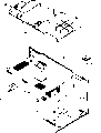
Fig. 3 is the exploded perspective illustration of first preferred embodiment of the invention micro-wave oven, and its aeration structure and fitting structure are shown;
The sectional view of Fig. 4 illustrates the air-flow of the micro-wave oven ventilating system of first preferred embodiment of the invention.
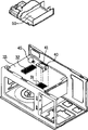
Fig. 5 is the exploded perspective illustration of the micro-wave oven of second preferred embodiment of the invention, and its aeration structure and fitting structure are shown;
Fig. 6 is the assembly drawing of the micro-wave oven among Fig. 5;
Fig. 7 is the sectional view of second preferred embodiment of the invention, and the air-flow of its aeration structure is shown.
The specific embodiment
Carefully referring to the preferred embodiments of the present invention, its example illustrates in the accompanying drawings now.Explain the aeration structure and the fitting structure thereof of first preferred embodiment of the invention referring to Fig. 3,4.The microwave oven component exploded perspective of Fig. 3 illustrates the aeration structure and the fitting structure thereof of first preferred embodiment of the invention, and the sectional view of Fig. 4 illustrates the air-flow of the micro-wave oven ventilating system of first preferred embodiment of the invention.
On inner chamber 30 end faces, therefore, the ventilating motor assembly 70 on inner chamber 30 end faces is from the place ahead suck air in the upper right corner and cool off electric apparatus room 35 applicable to the electric apparatus room 35 of micro-wave oven in the present invention.Referring to Fig. 3,4, micro-wave oven is divided into the inner chamber 30 of heated food and the electric apparatus room that electrical equipment is housed 35 on inner chamber 30.
In inner chamber 30 end face right part (see figure 3)s the air inlet light inlet window 31 of one suction air is arranged, one gas outlet 32 is arranged at the middle part of inner chamber 30 end faces.Air inlet light inlet window 31 and gas outlet 32 all are porous.The lamp bracket 40 of a shape or shape in the upper fixed of air inlet light inlet window 31.Bulb 45 installs in the pilot hole 41 that forms in lamp bracket 40 sides, and light shines the inside of inner chamber 30 by air inlet light inlet window 31.Airway 50 is arranged above the inner chamber 30, and the guiding air flows to air inlet light inlet window 31 from the top of inner chamber 30 and flows out from the gas outlet.The base plate 80 of installation is arranged in the bottom of electric apparatus room 35, and its height is high together with inner chamber 30, but the holding electrical parts, as magnetron 60 and high-tension transformer 61.Ventilating motor assembly 70 is installed to the rear portion of inner chamber 30 end face central authorities, is the major impetus that air is flowed in micro-wave oven.The two ends of ventilating motor assembly 70 are air inlet 71 and 72, can suck surrounding air and are discharged into outside the micro-wave oven, thereby form flowing of microwave furnace air.
Referring to accompanying drawing, the ventilation method of micro-wave oven aeration structure of first preferred embodiment of the invention and the illumination of fitting structure thereof are described.
Cool off electric equipment by the portion of air that the air grid (not shown) that is contained in front, micro-wave oven top enters above the electric apparatus room 35, as magnetron 60, high-tension transformer 61 etc., inspiration ventilating motor assembly right side import 71 is also discharged outside the micro-wave oven.The air inlet light inlet window 31 of remaining air through being formed on inner chamber 30 tops by air-inlet grille enters inner chamber 30.
Simultaneously, the steam that the air that enters inner chamber 30 generates in the inner chamber during with culinary art flows out from the gas outlet at inner chamber 30 tops, and is directed into left side air inlet 72 along the profile of airway 50.During microwave oven cooking, the light of bulb 45 illuminates the inside of inner chamber 30 by the air inlet light inlet window 31 of inner chamber 30 end faces.In this case, the air cooling that bulb 45 is entered inner chamber 30 among first embodiment by air inlet light inlet window 31.Moreover, in first embodiment, the steam that food sends when culinary art inner chamber 30 can not contacted with oil-containing gases with the bulb 45 that is contained in air inlet light inlet window 31 tops from air inlet light inlet window 31 defluent air.
Referring to Fig. 5 to 7, the aeration structure and the fitting structure thereof of explanation second preferred embodiment of the invention among the figure.Fig. 5 illustrates the exploded perspective illustration of micro-wave oven, and the aeration structure and the fitting structure thereof of second preferred embodiment of the invention is shown.Fig. 6 is the assembly drawing of the micro-wave oven among Fig. 5, and the sectional view of Fig. 7 illustrates the air-flow of the aeration structure of second preferred embodiment of the invention.
As shown in the figure, the ventilating motor that left and right fan 103a, 103b be housed is installed in the upper surface at ventilating duct 102 rear portions.The end face of the airway of box-like is an opening, and there is a gas outlet 102a in its front, and the air that left and right side fan 103a and 103b can be come out is discharged.A side is one to have the lamp bracket 104 of pilot hole 104a below ventilating duct 102 bottom surfaces.A bulb 106 is contained among the pilot hole 104a of lamp bracket 104.Airway 102 belows are inner chamber 112, i.e. cooking space.There is the air inlet light inlet window 112c of a porous at the inner chamber 112 end faces one side position relative with bulb 106 positions, and promptly bulb 106 emits beam and illuminates the cooking space of inner chamber 112 by air inlet light inlet window 112c.
One training wall 114 is arranged on the inner chamber of air inlet light inlet window 112c right flank.Training wall 114 guides the portion of air that is drawn into micro-wave oven air grid (not shown) front portion because of the draft of ventilating motor 103 right side fan 103a, makes it to flow to air inlet light inlet window 112c.
The gas outlet 112b that one porous is arranged on the right side part of inner chamber 112 end faces is formed directly into the end face of inner chamber 112.Air in the inner chamber 112 is discharged to outside the inner chamber 112 by gas outlet 112b, and is discharged to outside the micro-wave oven by the left fan 103b that is fixed on the ventilating motor 103 on the airway 102.
Fig. 7 is the vertical section of inner chamber, and the air-flow f when micro-wave oven of the present invention being shown ventilating shows that air enters inner chamber 112 through the air inlet light inlet window 112c of inner chamber 112 end faces well, by the cooling space in the inner chamber 112, and discharges through gas outlet 112b.
The ventilation operation of second preferred embodiment of the invention aeration structure is described now.
Air-flow when earlier running of microwave oven being described in the inner chamber.Air enters micro-wave oven from the positive right side of face of air grid (not shown) under the effect of the right side of the ventilating motor 103 that is installed in airway 102 rear portions fan 103a.Enter the diversed wall 114 of microwave furnace air separately, the diversed wall 114 guiding air inlet light inlet window 112c of portion of air, remaining air flows to electric apparatus room 113.In view of the above, enter the electric apparatus room of the air cooling of electric apparatus room at top, microwave Shanghai, the airway 102 following spatial flows that pass through that guided by training wall 114 steep to the air-cooled lamp of air inlet light inlet window 112c.Therefore, the bulb that is fixed on the lamp bracket 104 of airway 102 bottoms is fully cooled off by said flow.Air-flow can prevent downwards that from air inlet light inlet window 112c the steam etc. the inner chamber 112 from overflowing from air inlet light inlet window 112c.Take away the steam in the inner chamber 112 when on the other hand, the air that enters inner chamber 112 through the air inlet light inlet window is passing gas outlet 112b.Air-flow in the micro-wave oven aeration structure of the f1 among Fig. 7, f2, f3 explanation second preferred embodiment of the invention, wherein air is pressed direction shown in the f1 by air inlet gas production window 112c by the training wall guiding, in inner chamber 112, press shown in the f2 and flow, press shown in the f3 by the air behind the 112b of gas outlet and flow.
Simultaneously, training wall 114 can be made of one with airway 102, or is made of one with the end face of inner chamber 112, or an independent member.The lamp bracket 104 of air inlet light inlet window 112c top also can be made of one with airway 102.
First or second embodiment of micro-wave oven aeration structure of the present invention has the following advantages:
In the micro-wave oven aeration structure of the present invention, the part of air that enters micro-wave oven by air grid enters inner chamber through the air inlet light inlet window, and bulb is contained in certain position, air inlet light inlet window top.Therefore, unlike the prior art,,, when having reduced the assembler, saved production cost so can save the heat resistant adhesive tape that is attached on the air inlet light inlet window because air can not reflux by the air inlet light inlet window.
And, owing to the air that enters inner chamber through the air inlet light inlet window can cool off bulb, so bulb life prolongs.
Distance on the inner chamber between air inlet light inlet window and the gas outlet so airway is shorter, has been saved material less than this distance of the prior art, has alleviated product weight.
The aeration structure of prior art requires have an independent air inlet that air is introduced inner chamber in a side of inner chamber, but aeration structure of the present invention makes the light lumine inner chamber and makes air enter inner chamber with a public air inlet light inlet window, so simplified manufacturing process saves production cost.
Those of ordinary skill to present technique is apparent, and micro-wave oven aeration structure of the present invention can be done various modifications or change under the prerequisite that does not break away from essence of the present invention and scope.Therefore, in the scope of the appended claims of the present invention or its equivalent, make an amendment and change all and be included in the present invention.
Claims (11)
1. the aeration structure of a micro-wave oven, this micro-wave oven have the inner chamber and the inner electric apparatus room that electrical equipment is installed that form cooking space therein, and it is characterized in that described aeration structure comprises:
The air inlet light inlet window is formed on inner chamber end face one side, and the air and the light that a part can be entered electric apparatus room are introduced inner chamber;
The gas outlet is formed on inner chamber end face opposite side, and the air in the inner chamber is discharged to outside the inner chamber;
Base plate is installed, and it is formed on electric apparatus room bottom and highly identical with the top of inner chamber;
Ventilating motor assembly is installed in a side of inner chamber top, is used for the steam of inner chamber etc. is extracted and is discharged to outside the inner chamber by the gas outlet, and heat absorption and discharge that electric equipment in the electric apparatus room is sent; And
Airway is installed in the inner chamber top, and it is separated out the air duct and the air duct by electric apparatus room suction ventilation motor sub-assembly that are discharged into the outer also suction ventilation motor sub-assembly of inner chamber by the gas outlet.
2. the aeration structure in the claim 1 is characterized in that, airway is the box-like with open top face, and the front has outlet, and the air that ventilating motor assembly can be blown out is discharged by air grid.
3. the aeration structure in the claim 1 is characterized in that, also comprises the training wall that is positioned on the inner chamber end face, the air that enters electric apparatus room can be told a part and guide this part air into the air inlet light inlet window.
4. the aeration structure of claim 3 is characterized in that, training wall and airway are made of one.
5. the aeration structure of claim 3 is characterized in that, training wall is formed on the inner chamber end face, and is made of one with it.
6. the aeration structure of claim 1 is characterized in that, also is included in the bulb between airway and the air inlet light inlet window, is used for the illumination of inner chamber inside.
7. the aeration structure of claim 6 is characterized in that, bulb installs on the lamp bracket, and lamp bracket is fixed on the airway bottom.
8. the aeration structure of claim 7 is characterized in that, lamp bracket is shape or shape.
9. micro-wave oven is characterized in that it comprises:
Inner chamber, the inner cooking space that forms;
Electric apparatus room, the inner electrical equipment of installing;
The air inlet light inlet window is formed on inner chamber end face one side, is used for the portion of air and the light that enter electric apparatus room are introduced inner chamber;
The gas outlet is formed on inner chamber end face opposite side, is used for the air of inner chamber is discharged to outside the inner chamber;
Base plate is installed, and it is formed on electric apparatus room bottom and highly identical with the top of inner chamber;
Ventilating motor assembly is installed in the side on inner chamber top, is used for the steam etc. of aspiration lumen and is discharged to outside the inner chamber, and absorb electric equipment produces in the electric apparatus room heat and with its discharge;
Airway is installed to inner chamber top and separates with inner chamber, and it is separated out the air duct and the air duct by electric apparatus room suction ventilation motor sub-assembly that are discharged to the outer and suction ventilation motor sub-assembly of inner chamber by the gas outlet;
Lamp bracket is installed between airway and the air inlet light inlet window, is used to adorn bulb; And
Bulb installs on the lamp bracket, is used for the illumination of inner chamber inside.
10. the micro-wave oven of claim 9 is characterized in that, lamp bracket as an integral installation in airway bottom.
11. the micro-wave oven of claim 9 is characterized in that, lamp bracket is shape or shape.
Applications Claiming Priority (4)
| Application Number | Priority Date | Filing Date | Title |
|---|---|---|---|
| KR2020000037320U KR200232523Y1 (en) | 2000-12-30 | 2000-12-30 | Structure of ventilation of cavity for microwave oven |
| KR37324/2000 | 2000-12-30 | ||
| KR2020000037324U KR200232526Y1 (en) | 2000-12-30 | 2000-12-30 | The mounting structure of oven lamp for microwave oven |
| KR37320/2000 | 2000-12-30 |
Publications (2)
| Publication Number | Publication Date |
|---|---|
| CN1363800A CN1363800A (en) | 2002-08-14 |
| CN1166894C true CN1166894C (en) | 2004-09-15 |
Family
ID=36709996
Family Applications (1)
| Application Number | Title | Priority Date | Filing Date |
|---|---|---|---|
| CNB011386924A Expired - Fee Related CN1166894C (en) | 2000-12-30 | 2001-12-28 | Ventilation structure for microwave oven and lamp structure |
Country Status (4)
| Country | Link |
|---|---|
| US (1) | US6707019B2 (en) |
| EP (1) | EP1220575B1 (en) |
| CN (1) | CN1166894C (en) |
| DE (1) | DE60121127T2 (en) |
Families Citing this family (12)
| Publication number | Priority date | Publication date | Assignee | Title |
|---|---|---|---|---|
| US6894260B2 (en) * | 2001-12-04 | 2005-05-17 | Matsushita Electric Industrial Co., Ltd. | High frequency heating apparatus |
| KR100582306B1 (en) * | 2003-11-05 | 2006-05-22 | 엘지전자 주식회사 | Over The Range |
| KR20050053946A (en) * | 2003-12-03 | 2005-06-10 | 삼성전자주식회사 | Wall mounted type microwave oven |
| US6878915B1 (en) | 2004-03-19 | 2005-04-12 | Maytag Corporation | Air flow system for microwave cooking appliance |
| KR100609910B1 (en) | 2004-08-04 | 2006-08-09 | 삼성전자주식회사 | Microwave oven |
| FR2878536B1 (en) * | 2004-11-30 | 2007-04-06 | Analyses Mesures Pollutions A | METHOD FOR CONTINUOUS TEXTILE ENNOBLICATION AND INSTALLATION USING THE SAME |
| US8698057B2 (en) * | 2007-01-26 | 2014-04-15 | Lg Electronics Inc. | Ventilation hooded microwave oven and cooling system for the same |
| KR20090104943A (en) * | 2008-04-01 | 2009-10-07 | 엘지전자 주식회사 | Electric oven |
| WO2009145566A2 (en) * | 2008-05-29 | 2009-12-03 | 엘지전자 주식회사 | Cooker |
| CN101749749A (en) * | 2008-12-02 | 2010-06-23 | 乐金电子(天津)电器有限公司 | Hot air convection type microwave oven |
| US8375849B2 (en) | 2009-09-01 | 2013-02-19 | Manitowoc Foodservice Companies, Llc | Method and apparatus for an air inlet in a cooking device |
| CN106900099B (en) * | 2017-02-28 | 2020-10-23 | 广东美的厨房电器制造有限公司 | Cooking device |
Family Cites Families (15)
| Publication number | Priority date | Publication date | Assignee | Title |
|---|---|---|---|---|
| US3681557A (en) * | 1969-10-23 | 1972-08-01 | Mitsubishi Electric Corp | Electronic cooking apparatus |
| US4403128A (en) * | 1976-03-11 | 1983-09-06 | Sharp Kabushiki Kaisha | Microwave oven with a capability of functioning as an electric heating oven |
| JPS5421639A (en) * | 1977-07-19 | 1979-02-19 | Matsushita Electric Ind Co Ltd | High frequency heater |
| JPS54162245A (en) * | 1978-06-13 | 1979-12-22 | Matsushita Electric Ind Co Ltd | High-frequency heating device |
| US4254450A (en) * | 1978-08-21 | 1981-03-03 | General Electric Company | Lamp assembly for combination microwave oven and exhaust vent |
| JPS58203322A (en) * | 1982-05-20 | 1983-11-26 | Matsushita Electric Ind Co Ltd | High frequency heating device |
| IT209172Z2 (en) * | 1985-11-28 | 1988-09-16 | Zanussi Elettrodomestici | BUILT-IN MICROWAVE OVEN. |
| JPS63189714A (en) * | 1987-01-30 | 1988-08-05 | Matsushita Electric Ind Co Ltd | Microwave heater |
| JPS63281384A (en) * | 1987-05-14 | 1988-11-17 | Matsushita Electric Ind Co Ltd | High frequency heating device |
| JPH06101848A (en) * | 1992-09-22 | 1994-04-12 | Matsushita Electric Ind Co Ltd | High frequency heating device |
| DE4238660C2 (en) * | 1992-11-16 | 1994-09-01 | Bosch Siemens Hausgeraete | Oven, in particular with a device for pyrolytic self-cleaning |
| KR950011628B1 (en) * | 1992-11-27 | 1995-10-06 | 엘지전자주식회사 | Humidity detect device and method of range |
| KR100229138B1 (en) * | 1997-03-22 | 1999-11-01 | 윤종용 | A filter in microwave oven |
| SE518645C2 (en) * | 1997-07-17 | 2002-11-05 | Whirlpool Co | Household appliance with flow control means |
| KR100335050B1 (en) * | 1999-07-06 | 2002-05-02 | 구자홍 | multiple micro wave oven |
-
2001
- 2001-12-10 US US10/006,138 patent/US6707019B2/en not_active Expired - Fee Related
- 2001-12-19 DE DE60121127T patent/DE60121127T2/en not_active Expired - Fee Related
- 2001-12-19 EP EP01130307A patent/EP1220575B1/en not_active Expired - Lifetime
- 2001-12-28 CN CNB011386924A patent/CN1166894C/en not_active Expired - Fee Related
Also Published As
| Publication number | Publication date |
|---|---|
| EP1220575A3 (en) | 2004-03-03 |
| US6707019B2 (en) | 2004-03-16 |
| EP1220575A2 (en) | 2002-07-03 |
| DE60121127T2 (en) | 2007-02-01 |
| DE60121127D1 (en) | 2006-08-10 |
| CN1363800A (en) | 2002-08-14 |
| US20020084269A1 (en) | 2002-07-04 |
| EP1220575B1 (en) | 2006-06-28 |
Similar Documents
| Publication | Publication Date | Title |
|---|---|---|
| CN1166894C (en) | Ventilation structure for microwave oven and lamp structure | |
| CN1159548C (en) | Apparatus for cooling electrical equipment of air exhaust hood type microwave oven | |
| KR101311398B1 (en) | Lamp | |
| CN1174189C (en) | Wall microwave oven | |
| CN1159550C (en) | Microwav eoven heater system | |
| CN1102219C (en) | Microwave oven | |
| CN1459587A (en) | Wall microwave oven | |
| CN112914348A (en) | Cooking device | |
| CN1159546C (en) | Microwave oven | |
| CN1159549C (en) | Hood for microwave oven | |
| CN1531838A (en) | Built-in microwave oven | |
| CN1236235C (en) | Wall-mounted type microwave oven | |
| CN110925658A (en) | LED street lamp convenient for heat dissipation | |
| JP3737965B2 (en) | Electrical room structure of microwave oven | |
| CN1508478A (en) | Wall-type microwave oven | |
| CN1761386A (en) | Heat sink for light cluster of light-emitting diode | |
| KR200232523Y1 (en) | Structure of ventilation of cavity for microwave oven | |
| CN1474093A (en) | Microwave oven | |
| CN221005020U (en) | Stage lamp | |
| CN1891054A (en) | Electric oven discharge filter assembling structure | |
| CN1265128C (en) | Air flow system for microwave oven | |
| CN1274995C (en) | Cooling device for door of microwave oven | |
| CN210567658U (en) | Lamp set | |
| CN114484327B (en) | Household appliance | |
| CN220896870U (en) | Assembly structure of microwave oven lamp |
Legal Events
| Date | Code | Title | Description |
|---|---|---|---|
| C10 | Entry into substantive examination | ||
| SE01 | Entry into force of request for substantive examination | ||
| C06 | Publication | ||
| PB01 | Publication | ||
| C14 | Grant of patent or utility model | ||
| GR01 | Patent grant | ||
| CF01 | Termination of patent right due to non-payment of annual fee |
Granted publication date: 20040915 Termination date: 20151228 |
|
| EXPY | Termination of patent right or utility model |