CN116431110A - Method and system for generating automated engineering projects in technology installation using multidisciplinary methods - Google Patents
Method and system for generating automated engineering projects in technology installation using multidisciplinary methods Download PDFInfo
- Publication number
- CN116431110A CN116431110A CN202310023090.5A CN202310023090A CN116431110A CN 116431110 A CN116431110 A CN 116431110A CN 202310023090 A CN202310023090 A CN 202310023090A CN 116431110 A CN116431110 A CN 116431110A
- Authority
- CN
- China
- Prior art keywords
- processing unit
- automation
- engineering
- graph
- name
- Prior art date
- Legal status (The legal status is an assumption and is not a legal conclusion. Google has not performed a legal analysis and makes no representation as to the accuracy of the status listed.)
- Pending
Links
- 238000000034 method Methods 0.000 title claims abstract description 85
- 238000009434 installation Methods 0.000 title claims abstract description 55
- 238000005516 engineering process Methods 0.000 title abstract description 7
- 238000012545 processing Methods 0.000 claims abstract description 136
- 238000012986 modification Methods 0.000 claims abstract description 24
- 230000004048 modification Effects 0.000 claims abstract description 24
- 238000004458 analytical method Methods 0.000 claims abstract description 11
- 238000004088 simulation Methods 0.000 claims description 17
- 238000010586 diagram Methods 0.000 claims description 13
- 230000006870 function Effects 0.000 claims description 6
- 238000013459 approach Methods 0.000 claims description 4
- 238000004590 computer program Methods 0.000 claims description 3
- 238000013507 mapping Methods 0.000 claims description 2
- 230000010354 integration Effects 0.000 claims 1
- 230000008569 process Effects 0.000 abstract description 23
- 238000004891 communication Methods 0.000 description 10
- 230000003287 optical effect Effects 0.000 description 5
- 238000012795 verification Methods 0.000 description 4
- 238000004519 manufacturing process Methods 0.000 description 3
- 230000006399 behavior Effects 0.000 description 2
- 238000013461 design Methods 0.000 description 2
- 238000011161 development Methods 0.000 description 2
- 239000003607 modifier Substances 0.000 description 2
- 230000002093 peripheral effect Effects 0.000 description 2
- 239000004065 semiconductor Substances 0.000 description 2
- 238000012360 testing method Methods 0.000 description 2
- 230000003542 behavioural effect Effects 0.000 description 1
- 238000004422 calculation algorithm Methods 0.000 description 1
- 230000008859 change Effects 0.000 description 1
- 238000010276 construction Methods 0.000 description 1
- 238000012217 deletion Methods 0.000 description 1
- 230000037430 deletion Effects 0.000 description 1
- 238000004870 electrical engineering Methods 0.000 description 1
- 230000008676 import Effects 0.000 description 1
- 239000004973 liquid crystal related substance Substances 0.000 description 1
- 230000005055 memory storage Effects 0.000 description 1
- 238000003058 natural language processing Methods 0.000 description 1
- 238000004064 recycling Methods 0.000 description 1
- 239000007787 solid Substances 0.000 description 1
- 238000012800 visualization Methods 0.000 description 1
Images

Classifications
-
- G—PHYSICS
- G06—COMPUTING; CALCULATING OR COUNTING
- G06F—ELECTRIC DIGITAL DATA PROCESSING
- G06F8/00—Arrangements for software engineering
- G06F8/30—Creation or generation of source code
- G06F8/31—Programming languages or programming paradigms
-
- G—PHYSICS
- G06—COMPUTING; CALCULATING OR COUNTING
- G06F—ELECTRIC DIGITAL DATA PROCESSING
- G06F40/00—Handling natural language data
- G06F40/10—Text processing
- G06F40/12—Use of codes for handling textual entities
- G06F40/14—Tree-structured documents
- G06F40/143—Markup, e.g. Standard Generalized Markup Language [SGML] or Document Type Definition [DTD]
-
- G—PHYSICS
- G06—COMPUTING; CALCULATING OR COUNTING
- G06F—ELECTRIC DIGITAL DATA PROCESSING
- G06F8/00—Arrangements for software engineering
- G06F8/30—Creation or generation of source code
- G06F8/34—Graphical or visual programming
-
- G—PHYSICS
- G05—CONTROLLING; REGULATING
- G05B—CONTROL OR REGULATING SYSTEMS IN GENERAL; FUNCTIONAL ELEMENTS OF SUCH SYSTEMS; MONITORING OR TESTING ARRANGEMENTS FOR SUCH SYSTEMS OR ELEMENTS
- G05B19/00—Programme-control systems
- G05B19/02—Programme-control systems electric
- G05B19/04—Programme control other than numerical control, i.e. in sequence controllers or logic controllers
- G05B19/042—Programme control other than numerical control, i.e. in sequence controllers or logic controllers using digital processors
- G05B19/0426—Programming the control sequence
-
- G—PHYSICS
- G05—CONTROLLING; REGULATING
- G05B—CONTROL OR REGULATING SYSTEMS IN GENERAL; FUNCTIONAL ELEMENTS OF SUCH SYSTEMS; MONITORING OR TESTING ARRANGEMENTS FOR SUCH SYSTEMS OR ELEMENTS
- G05B19/00—Programme-control systems
- G05B19/02—Programme-control systems electric
- G05B19/418—Total factory control, i.e. centrally controlling a plurality of machines, e.g. direct or distributed numerical control [DNC], flexible manufacturing systems [FMS], integrated manufacturing systems [IMS] or computer integrated manufacturing [CIM]
- G05B19/4188—Total factory control, i.e. centrally controlling a plurality of machines, e.g. direct or distributed numerical control [DNC], flexible manufacturing systems [FMS], integrated manufacturing systems [IMS] or computer integrated manufacturing [CIM] characterised by CIM planning or realisation
-
- G—PHYSICS
- G06—COMPUTING; CALCULATING OR COUNTING
- G06F—ELECTRIC DIGITAL DATA PROCESSING
- G06F40/00—Handling natural language data
- G06F40/10—Text processing
- G06F40/12—Use of codes for handling textual entities
- G06F40/137—Hierarchical processing, e.g. outlines
-
- G—PHYSICS
- G06—COMPUTING; CALCULATING OR COUNTING
- G06F—ELECTRIC DIGITAL DATA PROCESSING
- G06F8/00—Arrangements for software engineering
- G06F8/20—Software design
-
- G—PHYSICS
- G06—COMPUTING; CALCULATING OR COUNTING
- G06F—ELECTRIC DIGITAL DATA PROCESSING
- G06F8/00—Arrangements for software engineering
- G06F8/40—Transformation of program code
- G06F8/41—Compilation
- G06F8/44—Encoding
- G06F8/447—Target code generation
-
- G—PHYSICS
- G06—COMPUTING; CALCULATING OR COUNTING
- G06F—ELECTRIC DIGITAL DATA PROCESSING
- G06F8/00—Arrangements for software engineering
- G06F8/60—Software deployment
- G06F8/61—Installation
-
- G—PHYSICS
- G06—COMPUTING; CALCULATING OR COUNTING
- G06F—ELECTRIC DIGITAL DATA PROCESSING
- G06F8/00—Arrangements for software engineering
- G06F8/70—Software maintenance or management
- G06F8/71—Version control; Configuration management
-
- G—PHYSICS
- G06—COMPUTING; CALCULATING OR COUNTING
- G06N—COMPUTING ARRANGEMENTS BASED ON SPECIFIC COMPUTATIONAL MODELS
- G06N5/00—Computing arrangements using knowledge-based models
- G06N5/02—Knowledge representation; Symbolic representation
-
- G—PHYSICS
- G06—COMPUTING; CALCULATING OR COUNTING
- G06Q—INFORMATION AND COMMUNICATION TECHNOLOGY [ICT] SPECIALLY ADAPTED FOR ADMINISTRATIVE, COMMERCIAL, FINANCIAL, MANAGERIAL OR SUPERVISORY PURPOSES; SYSTEMS OR METHODS SPECIALLY ADAPTED FOR ADMINISTRATIVE, COMMERCIAL, FINANCIAL, MANAGERIAL OR SUPERVISORY PURPOSES, NOT OTHERWISE PROVIDED FOR
- G06Q10/00—Administration; Management
- G06Q10/06—Resources, workflows, human or project management; Enterprise or organisation planning; Enterprise or organisation modelling
- G06Q10/063—Operations research, analysis or management
- G06Q10/0631—Resource planning, allocation, distributing or scheduling for enterprises or organisations
-
- G—PHYSICS
- G06—COMPUTING; CALCULATING OR COUNTING
- G06Q—INFORMATION AND COMMUNICATION TECHNOLOGY [ICT] SPECIALLY ADAPTED FOR ADMINISTRATIVE, COMMERCIAL, FINANCIAL, MANAGERIAL OR SUPERVISORY PURPOSES; SYSTEMS OR METHODS SPECIALLY ADAPTED FOR ADMINISTRATIVE, COMMERCIAL, FINANCIAL, MANAGERIAL OR SUPERVISORY PURPOSES, NOT OTHERWISE PROVIDED FOR
- G06Q10/00—Administration; Management
- G06Q10/06—Resources, workflows, human or project management; Enterprise or organisation planning; Enterprise or organisation modelling
- G06Q10/067—Enterprise or organisation modelling
-
- G—PHYSICS
- G06—COMPUTING; CALCULATING OR COUNTING
- G06Q—INFORMATION AND COMMUNICATION TECHNOLOGY [ICT] SPECIALLY ADAPTED FOR ADMINISTRATIVE, COMMERCIAL, FINANCIAL, MANAGERIAL OR SUPERVISORY PURPOSES; SYSTEMS OR METHODS SPECIALLY ADAPTED FOR ADMINISTRATIVE, COMMERCIAL, FINANCIAL, MANAGERIAL OR SUPERVISORY PURPOSES, NOT OTHERWISE PROVIDED FOR
- G06Q10/00—Administration; Management
- G06Q10/10—Office automation; Time management
- G06Q10/101—Collaborative creation, e.g. joint development of products or services
Landscapes
- Engineering & Computer Science (AREA)
- Theoretical Computer Science (AREA)
- General Engineering & Computer Science (AREA)
- Physics & Mathematics (AREA)
- General Physics & Mathematics (AREA)
- Software Systems (AREA)
- Business, Economics & Management (AREA)
- Human Resources & Organizations (AREA)
- Entrepreneurship & Innovation (AREA)
- Strategic Management (AREA)
- Economics (AREA)
- Computational Linguistics (AREA)
- Quality & Reliability (AREA)
- Artificial Intelligence (AREA)
- Operations Research (AREA)
- Marketing (AREA)
- Tourism & Hospitality (AREA)
- General Business, Economics & Management (AREA)
- Health & Medical Sciences (AREA)
- General Health & Medical Sciences (AREA)
- Audiology, Speech & Language Pathology (AREA)
- Data Mining & Analysis (AREA)
- Computing Systems (AREA)
- Automation & Control Theory (AREA)
- Development Economics (AREA)
- Educational Administration (AREA)
- Game Theory and Decision Science (AREA)
- Evolutionary Computation (AREA)
- Mathematical Physics (AREA)
- Computer Security & Cryptography (AREA)
- Manufacturing & Machinery (AREA)
- Stored Programmes (AREA)
- Management, Administration, Business Operations System, And Electronic Commerce (AREA)
Abstract
Methods and systems for generating automated engineering projects in technology installation using multidisciplinary methods. The present invention provides a method and system for generating automated process items in a technical installation (106). The method includes receiving, by a processing unit (202), a request to generate an automation program for a technical installation (106). The method also includes generating a first name graph based on information about a hardware configuration associated with the automation project. The method further includes generating, by the processing unit (202), a second name graph based on an analysis of one or more modifications to the hardware configuration of the technical installation (106). The method also includes generating, by the processing unit (202), an automation project from the plurality of engineering objects based on the comparison of the first name graph and the second name graph.
Description
The present invention relates to the field of computer-aided programming, and more particularly to a method and system for generating automated engineering programs in a technical installation using multidisciplinary methods.
Typically, multiple hardware devices are included in a technical installation. Examples of the plurality of hardware devices include motors, robots, logic controllers, human-machine interfaces, conveyor belts, and machine lathes. Deployment of multiple hardware devices into a technical installation requires expertise from professionals in multiple engineering disciplines. For example, in order to configure a hardware configuration associated with a hardware device, specialized knowledge of a hardware engineer is required. Similarly, in order to encode a plurality of engineering objects configured to automate a plurality of hardware devices, such as program files, open (openness) files, automated Markup Language (AML) files, memory objects, specialized knowledge of an automation engineer is required. Thus, hardware engineers and automation engineers need to work in concert with each other in order to deploy and automate multiple hardware devices in a technology installation. Therefore, a healthy exchange of technical information (regarding technical installation) between a hardware engineer and an automation engineer is of vital importance. However, automation engineers may find it difficult to understand the technical information provided by hardware engineers, especially when the technical information is provided in a data format that is not familiar to the automation engineers.
Accordingly, technical information about a plurality of hardware devices is exchanged between hardware and automation engineers using a commonly agreed format such as an Automation Markup Language (AML). In one example, the co-agreed-upon format is an information exchange format defined between an electrical engineering application and an automation application. In this case, the hardware engineer may have to manually encode technical information associated with the plurality of hardware devices into the exchange data file. The exchange data file is then imported and used by an automation engineer to generate a plurality of engineering objects.
Typically, a technical installation may have thousands of hardware devices, each having a particular hardware configuration. As the hardware configuration of each of thousands of hardware devices may have to be encoded as an exchange data file. Thus, a hardware engineer may have to manually encode thousands of lines of code to exchange technical information with an automation engineer.
In one use case, the hardware configuration of the technical installation is modified by the hardware engineer after the exchange data file is imported by the automation engineer. In this case, the hardware engineer must manually inform the automation engineer about the modified content. The hardware engineer may have to manually modify the exchange data file based on the modification notified by the hardware engineer. Exchanging data files includes a large number of data items. Thus, it is laborious for a hardware engineer to modify the exchange data file such that the integrity of the exchange data file is maintained. The automation engineer may then have to manually re-import the modified exchange data file or manually adapt the modifications in the plurality of engineering objects. An automation engineer may find it extremely difficult to modify multiple engineering objects while maintaining the integrity of the automation project.
Furthermore, exchanging data files cannot provide IT (information technology) tools that would enable IT engineers to integrate OT (operation technology) data with IT use cases. Thus, ensuring that technical information is exchanged between professionals of different engineering disciplines, and thus ensuring smooth generation of automated engineering projects, is laborious.
In view of the above, there is a need for an efficient method and system for generating automated engineering projects in a technical installation using multidisciplinary methods.
It is therefore an object of the present invention to provide a method and system for generating automated engineering items in a technical installation using a multidisciplinary approach. The object of the invention is achieved by a method for generating automated engineering projects in technical installations using multidisciplinary methods. The method includes receiving, by a processing unit, a request to generate a first automation item for a technical installation. The request includes information about hardware configurations associated with the plurality of hardware devices of the technical installation. Examples of the plurality of hardware devices include motors, robots, logic controllers, human-machine interfaces, conveyor belts, and machine lathes. Information about the hardware configuration is encoded into a first automated markup language script or the like. In one example, the hardware configuration is converted by the processing unit into a first automation markup language script. The hardware configuration includes power rating, voltage rating, durability, strength, electrical component configuration, symbol definition, voltage and wiring aspects associated with a plurality of hardware devices in a technical installation.
In a preferred embodiment, the first automated markup language script is encoded in an exchange data file for exchanging technical information between the hardware engineer and the automation engineer. The hardware configuration is encoded in a hierarchy in a first automated markup language script. The first automated markup language script includes information about interrelationships between a plurality of hardware devices and a plurality of engineering objects of the second automated project. The plurality of engineering objects includes software objects such as program files, open files, programming blocks, or memory objects. The second automation project is an existing project configured to control and automate a plurality of hardware devices in the technical installation. In one example, the second automation project is configured to automate a plurality of engineering objects.
In a preferred embodiment, the method further comprises analyzing, by the processing unit, the first automated markup language script to detect a plurality of nodes in the first automated markup language script. The method also includes converting, by the processing unit, each of the plurality of nodes into one or more knowledge graph triples (triples). Thus, hierarchical relationships within the first automated markup language script are converted into semantic representations of one or more knowledge graph triples. The method also includes generating, by the processing unit, a first name graph from the one or more knowledge graph triples. The first name graph includes a knowledge graph-based semantic representation of a hierarchical relationship between each of a plurality of nodes in the first automated markup language script.
The first name graph includes information regarding relationships between hardware configurations of a plurality of hardware devices and a plurality of engineering objects associated with an automation project. The method also includes receiving, by the processing unit, information from the user regarding one or more modifications in the hardware configuration of the plurality of hardware devices. In one example, a user may modify a hardware configuration of a plurality of hardware devices using an electrical designer application. In another example, a user may rearrange a plurality of hardware devices and rewire interconnections between the plurality of hardware devices to modify the hardware configuration of the plurality of hardware devices. In this case, the modification in the arrangement of the plurality of hardware devices is encoded as a second automated markup language script. The second automated markup language script includes information about a hierarchical relationship between the plurality of hardware devices after modifying the hardware configuration of the plurality of hardware devices.
In a preferred embodiment, the method further comprises analyzing, by the processing unit, the first name graph and one or more modifications in the hardware configuration of the plurality of hardware devices. The method further includes generating, by the processing unit, a second name graph based on an analysis of one or more modifications to the technically installed hardware configuration. The second name graph includes information regarding relationships between modified hardware configurations of the technical installation and the plurality of engineering objects.
The method also includes determining, by the processing unit, a first hierarchical path between at least two nodes of the first name graph and a second hierarchical path between corresponding nodes of the second name graph. The method also includes comparing, by the processing unit, the determined first tier path and the second tier path.
In a preferred embodiment, the method further comprises determining, by the processing unit, a plurality of differences between the first name graph and the second name graph based on the comparison. In one example, the plurality of differences are determined by the processing unit using a knowledge graph query process. The method also includes mapping, by the processing unit, the determined plurality of differences to one or more of the plurality of engineering objects. The method also includes modifying, by the processing unit, one or more of the plurality of engineering objects based on the second name graph. The method also includes generating, by the processing unit, an automation project from a plurality of engineering objects including one or more modified engineering objects.
In a preferred embodiment, the method further comprises analyzing, by the processing unit, the second name graph to generate one or more user suggestions for modifying the automated process. The method also includes displaying, by the processing unit, the one or more user suggestions to the one or more users.
In a preferred embodiment, the method includes generating, by a processing unit, a simulation instance for an industrial environment. The method also includes simulating, by the processing unit, deployment of the generated first automation project in the industrial environment by executing one or more functionalities of the first automation project on the generated simulation instance.
In a preferred embodiment, the method further comprises determining, by the processing unit, whether the generated first automation item is valid based on a result of the simulated execution of the generated first automation item. The method also includes deploying, by the processing unit, the first automation project in real-time onto the industrial environment based on the generated determination that the first automation project is valid. The method further includes displaying, by the processing unit, the automation item on one of the display devices.
The object of the invention is also achieved by an engineering system for generating automation engineering items in technical installations. An engineering system includes one or more processing units and a memory coupled to the processing units. The memory includes an automation module stored in the form of machine-readable instructions executable by the processing unit. The automation module is configured to perform the method as described above.
The object of the invention is also achieved by an industrial environment. The industrial environment includes an engineering system, a technical installation including one or more physical components, and one or more client devices communicatively coupled to the engineering system and the technical installation. The engineering system is configured to perform the above-described method steps.
The object of the invention is also achieved by a computer program product having stored therein machine-readable instructions which, when executed by one or more processing units, cause the one or more processing units to perform the method steps as described above.
The above and other features of the present invention will now be described with reference to the accompanying drawings. The illustrated embodiments are intended to illustrate, but not to limit the invention.
The invention will be further described with reference to the illustrated embodiments shown in the drawings, in which:
FIG. 1 is a block diagram of an industrial environment capable of generating automation items in a technical installation using a multidisciplinary approach in accordance with an embodiment of the present invention;
FIG. 2 is a block diagram of an engineering system such as that shown in FIG. 1, in which embodiments of the present invention may be implemented;
FIG. 3 is a block diagram of an automation module, such as that shown in FIG. 2, in which embodiments of the present invention may be implemented;
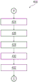
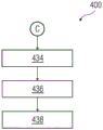
FIGS. 4A-D are process flow diagrams illustrating an exemplary method of generating an automated process according to embodiments of the invention; and
FIG. 5 is a process flow diagram illustrating an exemplary method of generating an automated process in accordance with an embodiment of the present invention.
Various embodiments are described with reference to the drawings, wherein like reference numerals are used to refer to like elements throughout. In the following description, for purposes of explanation, numerous specific details are set forth in order to provide a thorough understanding of one or more embodiments. It may be evident that such embodiment(s) may be practiced without these specific details.
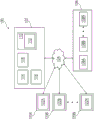
FIG. 1 is a block diagram of an industrial environment 100 capable of generating automation engineering projects in a technical installation 106, according to an embodiment of the invention. In FIG. 1, an industrial environment 100 includes an engineering system 102 that is controllable by one of a first automation project, a second automation project, and one or more client devices 120A-N. As used herein, an "industrial environment" refers to a processing environment that includes configurable computing physical and logical resources, such as networks, servers, storage, applications, services, etc., as well as data distributed across platforms such as cloud computing platforms. The first automation project and the second automation project are a collection of program, software configuration, hardware configuration, and wiring related documents that enable automation of the plurality of hardware devices 108A-N of the technical installation 106. Examples of the plurality of hardware devices 108A0N include servers, robots, switches, automation devices, programmable Logic Controllers (PLCs), human-machine interfaces (HMI), motors, valves, pumps, actuators, sensors, and other hardware device(s). The industrial environment 100 provides on-demand network access to a shared pool of configurable computing physical and logical resources. Engineering system 102 is communicatively connected to a plurality of hardware devices 108A-N of technical installation 106 via network 104, such as a Local Area Network (LAN), wide Area Network (WAN), wi-Fi, the Internet, any short-range or long-range communication. Engineering system 102 is also connected to one or more client devices 120A-N via network 104.
The first automation project and the second automation project include a plurality of project objects. Each of the plurality of engineering objects includes design information and source code associated with a particular aspect of the plurality of hardware devices 108A-N of the technical installation 106 or a particular industrial process. Examples of the plurality of engineering objects include design files, program logic controller blocks, tag tables, alarm objects, factory automation objects, program files, open files, automated Markup Language (AML) files, memory objects, and piping and instrumentation diagrams of technical installation 106. Each of the plurality of engineering objects may have a different specification of the plurality of specifications. The specification of the engineering object defines the purpose of the engineering object. The specifications include coding language, coding conventions, software configurations, processing speed limits, memory limits, and key process indicators associated with engineering objects. Each of the one or more engineering objects includes information and source code required to control a particular hardware device of the plurality of hardware devices 108A-N of the technical installation 106.
The plurality of engineering objects may also include source code associated with a hardware configuration of each of the plurality of hardware devices 108A-N of the technical installation 106. The plurality of hardware devices 108A-N may be connected to each other or to several other components (not shown in FIG. 1) via physical connections. The physical connection may be through wiring (cabling) between the plurality of hardware devices 108A-N. Alternatively, the plurality of hardware devices 108A-N may also be connected via non-physical connections, such as an Internet of things (IOT), and a 5G network. However, FIG. 1 shows engineering system 102 connected to a plurality of hardware devices 108A-N. It will be appreciated by those skilled in the art that the first and second automation items may be stored in a memory storage device of the engineering system 102 or in one or more servers located in different geographic locations.
The client devices 120A-N may access the engineering system 102 to automatically generate engineering projects. Client devices 120A-N may access a cloud application (such as providing a performance visualization of one or more engineering objects via a web browser). Throughout the specification, the terms "client device" and "user device" are used interchangeably.
FIG. 2 is a block diagram of engineering system 102, such as those shown in FIG. 1, in which embodiments of the present invention may be implemented. In FIG. 2, engineering system 102 includes a processing unit 202, an accessible memory 204, a storage unit 206, a communication interface 208, an input output unit 210, a network interface 212, and a bus 214.
As used herein, processing unit 202 represents any type of computational circuitry, such as, but not limited to, a micro-processing unit, a microcontroller, a complex instruction set computing micro-processing unit, a reduced instruction set computing micro-processing unit, a very long instruction word micro-processing unit, an explicit parallel instruction computing micro-processing unit, a graphics processing unit, a digital signal processing unit, or any other type of processing circuitry. The processing unit 202 may also include an embedded controller, such as a general purpose or programmable logic device or array, an application specific integrated circuit, a single chip computer, and the like.
The storage unit 206 may be a non-transitory storage medium configured to store a database (such as database 118) that includes server versions of one or more engineering objects 108A-N associated with an automation project.
The communication interface 208 is configured to establish a communication session between one or more client devices 120A-N and the engineering system 102. The communication interface 208 allows one or more engineering applications running on the client devices 120A-N to import/export engineering project files into the engineering system 102. In an embodiment, the communication interface 208 interacts with interfaces at one or more client devices 120A-N for allowing engineers to access automation engineering items associated with automation engineering item files and perform one or more actions on automation engineering items stored in the engineering system 102.
The input output unit 210 may include an input device capable of receiving one or more input signals, such as user commands to process an engineering project file, a keyboard, a touch-sensitive display, a camera (such as a camera that receives gesture-based inputs), and so forth. Furthermore, the input output unit 210 may be a display unit for displaying a graphical user interface that visualizes the behavioral model associated with the modified engineering project and also displays status information associated with each set of actions performed on the graphical user interface. The set of actions may include performing predefined tests, downloading, compiling, and deploying a graphics program. Bus 214 serves as an interconnect between processing unit 202, memory 204, and input-output unit 210.
The network interface 212 may be configured to handle network connectivity, bandwidth, and network traffic between the engineering system 102, the client devices 120A-N, and the automation projects.
Those of ordinary skill in the art will appreciate that the hardware depicted in FIG. 2 may vary depending on the particular implementation. For example, other peripheral devices, such as optical disk drives and the like, local Area Networks (LANs), wide Area Networks (WANs), wireless (e.g., wi-Fi) adapters, graphics adapters, disk controllers, input/output (I/O) adapters, in addition to or in place of the hardware depicted. The depicted examples are provided for purposes of explanation only and are not meant to imply architectural limitations with respect to the present disclosure.
Those skilled in the art will recognize that for simplicity and clarity, not all of the structure and operation of all data processing systems suitable for use with the present disclosure have been depicted or described herein. Instead, only as much of the engineering system 102 is depicted and described as is unique to the present disclosure or necessary for an understanding of the present disclosure. The remainder of the construction and operation of engineering system 102 may conform to any of the various current implementations and practices known in the art.
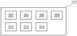
FIG. 3 is a block diagram of an automation module 112, such as those shown in FIG. 2, in which embodiments of the present invention may be implemented. In fig. 3, the automation module 112 includes a request processor module 302, an ontology generator module 304, an analysis module 306, a modifier module 308, an automation project database 310, a verification module 312, and a deployment module 314. Fig. 3 is explained in conjunction with fig. 1 and 2.
The request processor module 302 is configured to receive a request to generate an automated process. For example, a request is received from one of one or more users external to the industrial environment 100 via a network. In an alternative embodiment, the request is received from one or more client devices 120A-N via a network.
The ontology generator module 304 is configured to generate a name graph from hardware configuration files associated with the plurality of hardware devices 108A-N. In an embodiment, ontology generator module 304 is configured to generate a knowledge graph from a hardware configuration file. The hardware configuration file is encoded as an automated markup language script. The ontology generator module 304 is configured to analyze the automated markup language script to detect a plurality of nodes in the first automated markup language script. The ontology generator module 304 is configured to convert each of the plurality of nodes into one or more knowledge graph triples. The ontology generator module 304 is configured to generate a first name graph from one or more knowledge graph triples. The first name graph includes a knowledge graph-based semantic representation of hierarchical relationships between each of a plurality of nodes in an automated markup language script. In one example, the ontology generator module 304 is configured to analyze an automated markup language script by applying natural language processing algorithms on a hardware configuration.
The analysis module 306 is configured to analyze the name graph generated by the ontology generator module 304. In particular, the analysis module 306 is configured to map a plurality of nodes of the name graph to a plurality of hardware devices 108A-N of the technical installation 106. Furthermore, the analysis module 306 is configured to analyze the behavior of the plurality of hardware devices 108A-N based on the generated name graph.
The modifier module 308 is configured to modify one or more engineering objects based on the analysis of the name graph. One or more engineering objects are modified based on the analysis of the name graph. Modifications include any change, such as addition, deletion, update, replacement, or revision, of one or more variables, code lines, classes, functions, or annotations in one or more engineering objects. Thus, one or more engineering objects are modified based on relationships between sets of variables corresponding to a plurality of key process indicators associated with a plurality of industrial processes and automation projects. Thus, a plurality of engineering projects are generated based on relationships between a set of variables corresponding to each logical block in one or more engineering objects, a set of key process indicators associated with the one or more engineering objects, and an engineering domain of the automation engineering project.
The automation project database 310 is configured to store an automation project library comprising a plurality of project projects and a generated name graph. The automation project database 310 is configured to continuously update the automation project library with updated versions of the optimized project. In addition, the automation project database 310 is configured to maintain an automation project library in the generated name graph.
The verification module 312 is configured to generate a simulation instance for the industrial environment 100. In one example, the simulation instance is a digital twin of a plurality of hardware devices 108A-N operating in a technical installation 106 of the industrial environment 100. The verification module 312 is configured to simulate execution of the first automated engineering project on the plurality of hardware devices 108A-N in the simulation environment by executing the generated first engineering object on the generated simulation instance.
The deployment module 314 is configured to deploy the optimized engineering project onto the industrial environment 100 based on the verification. Advantageously, the optimized project is deployed only after it is determined that the optimized project is valid.
The automation module 112 causes the processing unit 202 to receive a request to generate a first automation item for a technical installation. The request includes information regarding hardware configurations associated with the plurality of hardware devices 108A-N of the technical installation 106.
Information about the hardware configuration is encoded as a first automated markup language script or the like. In one example, the hardware configuration is converted to a first automated markup language script by the processing unit 202. The hardware configuration includes power ratings, voltage ratings, durability, strength, electrical component configuration, symbol definition, voltage, and wiring aspects associated with the plurality of hardware devices 108A-N in the technical installation 106.
The first automated markup language script is encoded in an exchange data file for exchanging technical information between the hardware engineer and the automation engineer. The hardware configuration is encoded in a hierarchy in a first automated markup language script. The first automated markup language script includes information regarding interrelationships between the plurality of hardware devices 108A-N and a plurality of engineering objects of a second automated project stored in the database 114. The plurality of engineering objects includes software objects such as program files, open files, programming blocks, or memory objects. The second automation engineering project is an existing engineering project configured to control and automate the plurality of hardware devices 108A-N in the technical installation 106.
The automation module 112 also causes the processing unit 202 to analyze the first automated markup language script to detect a plurality of nodes in the first automated markup language script.
The automation module 112 also causes the processing unit 202 to convert each of the plurality of nodes into one or more knowledge graph triples. Thus, hierarchical relationships within the first automated markup language script are converted into semantic representations of one or more knowledge graph triples. The automation module 112 also causes the processing unit 202 to generate a first name graph from the one or more knowledge graph triples. The first name graph includes a knowledge graph-based semantic representation of a hierarchical relationship between each of a plurality of nodes in the first automated markup language script.
The first name graph includes information regarding relationships between hardware configurations of the plurality of hardware devices 108A-N and a plurality of engineering objects associated with the second automation project. The automation module 112 also causes the processing unit 202 to receive information from a user regarding one or more modifications in the hardware configuration of the plurality of hardware devices 108A-N via the processing unit. In one example, a user may modify the hardware configuration of the plurality of hardware devices 108A-N using an electrical designer application. In another example, a user may rearrange the plurality of hardware devices 108A-N and rewire interconnections between the plurality of hardware devices 108A-N to modify the hardware configuration of the plurality of hardware devices 108A-N. In this case, the modifications in the arrangement of the plurality of hardware devices 108A-N are encoded as a second automated markup language script. The second automated markup language script includes information about the hardware configuration of the plurality of hardware devices 108A-N after modifying the hardware configuration of the plurality of hardware devices 108A-N.
The automation module 112 also causes the processing unit 202 to analyze the first name graph and one or more modifications in the hardware configuration of the plurality of hardware devices. The automation module 112 also causes the processing unit 202 to generate a second name graph based on an analysis of one or more modifications to the technically installed hardware configuration. The second name graph includes information regarding relationships between modified hardware configurations of the technical installation and the plurality of engineering objects.
The automation module 112 also causes the processing unit 202 to determine a first hierarchical path between at least two nodes of the first name graph and a second hierarchical path between corresponding nodes of the second name graph. The automation module 112 also causes the processing unit 202 to compare the determined first tier path to the second tier path.
The automation module 112 also causes the processing unit 202 to determine a plurality of differences between the first name graph and the second name graph based on the comparison. In one example, the plurality of differences are determined by the processing unit using a knowledge graph query process. The automation module 112 also causes the processing unit 202 to map the determined plurality of differences to one or more of the plurality of engineering objects.
The automation module 112 also causes the processing unit 202 to modify one or more of the plurality of engineering objects based on the second name graph. The automation module 112 also causes the processing unit 202 to generate a first automation item from a plurality of engineering objects including one or more modified engineering objects.
The automation module 112 also causes the processing unit 202 to analyze the second name graph to generate one or more user suggestions for modifying the first automated process. The automation module 112 also causes the processing unit 202 to display one or more user suggestions to one or more users.
The automation module 112 also causes the processing unit 202 to generate a simulation instance of the industrial environment 100. The automation module 112 also causes the processing unit 202 to simulate the deployment of the generated first automation item in the industrial environment 100 by executing one or more functions of the first automation item on the generated simulation instance.
The automation module 112 also causes the processing unit 202 to determine whether the generated first automation item is valid based on a result of the simulated execution of the generated first automation item. The automation module 112 also causes the processing unit 202 to deploy the first automation project onto the industrial environment 100 in real-time based on the generated determination that the first automation project is valid. The method further includes displaying, by the processing unit, the first automation item on one of the display devices.
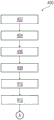
Fig. 4A-D are process flow diagrams illustrating an exemplary method 400 of generating an automated process in the engineering system 102 using a multidisciplinary approach in accordance with embodiments of the present invention.
At step 402, a request is received to generate a first automation item for a technical installation 106. The request includes information regarding hardware configurations associated with the plurality of hardware devices 108A-N of the technical installation 106. Information about the hardware configuration is encoded as a first automated markup language script or the like. In one example, the hardware configuration is converted to a first automated markup language script by the processing unit 202. The hardware configuration includes power ratings, voltage ratings, durability, strength, electrical component configuration, symbol definition, voltage, and wiring aspects associated with the plurality of hardware devices 108A-N in the technical installation 106.
The first automated markup language script is encoded in an exchange data file for exchanging technical information between the hardware engineer and the automation engineer. The hardware configuration is encoded in a hierarchy in a first automated markup language script. The first automated markup language script includes information regarding interrelationships between the plurality of hardware devices 108A-N and a plurality of engineering objects of a second automated project stored in the database 114. The plurality of engineering objects includes software objects such as program files, open files, programming blocks, or memory objects. The second automation engineering project is an existing engineering project configured to control and automate the plurality of hardware devices 108A-N in the technical installation 106.
At step 404, the processing unit 202 analyzes the first automated markup language script to detect a plurality of nodes in the first automated markup language script.
At step 406, each of the plurality of nodes is converted into one or more knowledge graph triples by the processing unit 202. Thus, hierarchical relationships within the first automated markup language script are converted into semantic representations of one or more knowledge graph triples.
At step 408, a first name graph is generated by processing unit 202 from the one or more knowledge graph triples. The first name graph includes a knowledge graph-based semantic representation of a hierarchical relationship between each of a plurality of nodes in the first automated markup language script. The first name graph includes information regarding relationships between hardware configurations of the plurality of hardware devices 108A-N and a plurality of engineering objects associated with the second automation project.
At step 410, the processing unit 202 receives information regarding one or more modifications in the hardware configuration of the plurality of hardware devices 108A-N. In one example, a user may modify the hardware configuration of the plurality of hardware devices 108A-N using an electrical designer application. In another example, a user may rearrange the plurality of hardware devices 108A-N and rewire the interconnections between the plurality of hardware devices 108A-N to modify the hardware configuration of the plurality of hardware devices 108A-N. In this case, the modification of the arrangement of the plurality of hardware devices 108A-N is encoded as a second automated markup language script. The second automated markup language script includes information about the hardware configuration of the plurality of hardware devices 108A-N after modifying the hardware configuration of the plurality of hardware devices 108A-N.
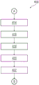
At step 412, the first name graph and one or more modifications in the hardware configuration of the plurality of hardware devices are analyzed by the processing unit 202.
At step 414, a second name graph is generated by the processing unit 202 based on an analysis of one or more modifications to the technically installed hardware configuration. The second name graph includes information regarding relationships between modified hardware configurations of the technical installation and the plurality of engineering objects.
At step 416, a first hierarchical path between at least two nodes of the first name graph and a second hierarchical path between corresponding nodes of the second name graph are determined by the processing unit 202.
At step 418, processing unit 202 compares the determined first tier path and second tier path.
At step 420, based on the comparison, a plurality of differences between the first name graph and the second name graph are determined by the processing unit 202. In one example, the plurality of differences are determined by the processing unit using a knowledge graph query process.
At step 422, the determined plurality of differences are mapped by the processing unit 202 to one or more of the plurality of engineering objects.
At step 424, one or more of the plurality of engineering objects is modified by the processing unit 202 based on the second name graph.
At step 426, a first automation item is generated by the processing unit 202 from a plurality of engineering objects including one or more modified engineering objects.
At step 428, the processing unit 202 analyzes the second name graph to generate one or more user suggestions for modifying the first automated process.
At step 430, one or more user suggestions are displayed to one or more users by the processing unit 202 via a display device, such as a Liquid Crystal Display (LCD) panel.
At step 432, a simulation instance for the industrial environment 100 is generated by the processing unit 202.
At step 434, the deployment of the generated first automation project in the industrial environment 100 is simulated by the processing unit 202 by executing one or more functions of the first automation project on the generated simulation instance.
At step 436, it is determined by the processing unit 202 whether the generated first automated process item is valid based on the results of the simulated execution of the generated first automated process item.
At step 438, the first automation item is deployed by the processing unit 202 onto the industrial environment 100 in real-time based on the determination that the generated first automation item is valid. The method further includes displaying, by the processing unit, the first automation item on one of the display devices.
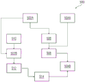
FIG. 5 is a process flow diagram 500 illustrating an exemplary method of generating an automated process in accordance with an embodiment of the present invention. Fig. 5 is explained in connection with fig. 1, 2, 3 and 4A-D.
The process flow diagram 500 shows a first hardware configuration file 502A and a first automation item 504A. The first automation item 504A includes a plurality of engineering objects configured to control a plurality of hardware devices 108A-N in the technical installation 106. The first hardware configuration file 502A includes information about the hardware configuration of each of the plurality of hardware devices 108A-N in the technical installation 106, such as wiring aspects, power ratings, voltage ratings, and the like. The first automation item 504B includes a plurality of engineering objects configured to control a plurality of hardware devices 108A-N. The plurality of engineering objects includes programming blocks, source code, program files, and the like.
The first hardware configuration file 502A is converted by the processing unit 202 into a first automation markup language script 506. The processing unit 202 is further configured to generate a first name graph 508 from the first engineering program and the first automated markup language script 506.
In one example, user 510 may introduce one or more modifications 502B to first hardware configuration file 502A. The processing unit 202 is further configured to convert the one or more modifications 502B into a second automation markup language script 512. The second automated markup language script is further converted by the processing unit 202 into a second name graph 514. The processing unit 202 is further configured to generate a second automation item 504B based on the plurality of differences between the first name graph 508 and the second name graph 514.
The invention can take the form of a computer program product comprising program modules accessible from a computer-usable or computer-readable medium storing program code for use by or in connection with one or more computers, processing units, or instruction execution systems. For the purposes of this description, a computer-usable or computer readable medium can be any apparatus that can contain, store, communicate, propagate, or transport the program for use by or in connection with the instruction execution system, apparatus, or device. The medium may be an electronic, magnetic, optical, electromagnetic, infrared, or semiconductor system (or apparatus or device) or a propagation medium in its own right, as the signal carrier is not included in the definition of physical computer-readable medium, including semiconductor or solid state memory, magnetic tape, a removable computer diskette, a Random Access Memory (RAM), a read-only memory (ROM), a rigid magnetic disk and an optical disk such as compact disk read-only memory (CD-ROM), optical disk read/write and DVD. As will be appreciated by those skilled in the art, both the processing unit and the program code for implementing each aspect of the present technology may be centralized or distributed (or a combination thereof).
While the invention has been described in detail with reference to certain embodiments, it should be understood that the invention is not limited to those embodiments. Many modifications and variations of this disclosure will be apparent to those skilled in the art without departing from the scope of the various embodiments of the invention as described herein. The scope of the invention is, therefore, indicated by the appended claims rather than by the foregoing description. All changes, modifications and variations that come within the meaning and range of equivalency of the claims are to be embraced within their scope. All advantageous embodiments claimed in the method claims can also be applied to the system/device claims.
Claims (13)
1. A method for generating an automation project in a technical installation (106) using a multidisciplinary approach, the method comprising:
receiving, by a processing unit (202), a request to generate a first automation item (504B) for a technical installation (106), wherein the request includes information (502A) of a hardware configuration associated with a plurality of hardware devices (108A-N) in the technical installation (106);
generating, by the processing unit (202), a first name graph (508) based on the information (502A) of the hardware configuration of the plurality of hardware devices (108A-N) and a second automation item (504A), wherein
The second automation project (504A) is configured to automate a plurality of engineering objects, and
the first name graph (508) includes information regarding a hardware configuration of the plurality of hardware devices (108A-N) and a relationship between the plurality of engineering objects associated with the second automation item (504A);
-receiving, by the processing unit (202), information from a user (510) regarding one or more modifications (502B) in the hardware configuration of a plurality of hardware devices (108A-N);
analyzing, by the processing unit (202), the first name graph (508) and the one or more modifications (502B) in the hardware configuration of the plurality of hardware devices (108A-N);
generating, by the processing unit (202), a second name graph (514) based on an analysis of the one or more modifications (502B) of the hardware configuration of the technical installation (106), wherein the second name graph (514) comprises information about a relationship between the modified hardware configuration of the technical installation (106) and the plurality of engineering objects;
generating, by the processing unit (202), the first automation item (504B) from the plurality of engineering objects based on a comparison of the first name graph (508) and the second name graph (514);
Generating, by the processing unit (202), a simulation instance for an industrial environment (100); and
simulating, by the processing unit (202), deployment of the generated first automation item in the industrial environment (100) by executing one or more functions of the first automation item on the generated simulation instance.
2. The method of claim 1, wherein the information (502A) about the hardware configuration is encoded as a first automation markup language script (506).
3. The method of claim 2, wherein generating the first name graph comprises:
analyzing, by the processing unit (202), the first automated markup language script (506) to detect a plurality of nodes in the first automated markup language script;
converting, by the processing unit (202), each node of the plurality of nodes into one or more knowledge graph triples; and
generating, by the processing unit (202), the first name graph (508) from the one or more knowledge graph triples, wherein the first name graph (508) includes a semantic representation of a hierarchical relationship between each of the plurality of nodes in the first automated markup language script (506).
4. A method according to claims 1 to 3, wherein generating the second name graph comprises:
converting, by the processing unit (202), the one or more modifications (502B) in the hardware configuration of the plurality of hardware devices (108A-N) into a second automated markup language script (512);
generating, by the processing unit (202), the second automated markup language script (512) as a knowledge graph instance;
integrating, by the processing unit (202), the knowledge graph instance into the first name graph (508); and
the second name graph (514) is generated by the processing unit (202) based on an integration of the knowledge graph instance into the first name graph.
5. A method according to claims 1 to 3, wherein generating the automation project comprises:
determining, by the processing unit (202), a plurality of differences between the first name graph (508) and the second name graph (514);
mapping, by the processing unit (202), the determined plurality of differences to one or more of the plurality of engineering objects;
modifying, by the processing unit (202), the one or more of the plurality of engineering objects based on the determined plurality of differences; and
The first automation item (504B) is generated by the processing unit (202) from the one or more modified engineering objects of the plurality of engineering objects.
6. The method of claim 4, wherein determining the plurality of differences between the first name graph (508) and the second name graph (514) comprises:
determining, by the processing unit (202), a first hierarchical path between at least two nodes of the first name graph and a second hierarchical path between corresponding nodes of the second name graph;
comparing, by the processing unit (202), the determined first hierarchical path and the second hierarchical path; and
the plurality of differences between the first name graph (508) and the second name graph (514) are determined by the processing unit (202) based on the comparison.
7. The method of claims 1 to 6, further comprising:
analyzing, by the processing unit (202), the second name graph to determine one or more user suggestions for modifying the first automation item (504B); and
the one or more user suggestions are displayed to one or more users by the processing unit (202).
8. The method of claims 1 to 7, wherein the one or more engineering objects (108A-N) are one of program files, open files, automated Markup Language (AML) files, memory objects, physical engineering devices, and pipe and instrumentation diagrams.
9. The method of claims 1 to 7, further comprising:
generating, by the processing unit (202), a simulation instance for an industrial environment (100); and
simulating, by the processing unit (202), deployment of the generated first automation item in the industrial environment (100) by executing one or more functions of the first automation item on the generated simulation instance.
10. The method of claim 9, further comprising:
determining, by the processing unit (202), whether the generated first automation item (504B) is valid based on a result of a simulation execution of the generated first automation item (504B);
deploying, by a processing unit (202), the first automation item onto the industrial environment (100) in real time based on determining that the generated first automation item is valid; and
-displaying, by the processing unit (202), the first automation item (504B) on one of the display devices (120 a-n).
11. An engineering system for generating automation engineering projects in a technical installation (106), wherein the engineering system comprises:
one or more processing units (202); and
A memory (204) coupled to the one or more processing units, wherein the memory comprises an automation module stored in the form of machine readable instructions executable by the one or more processing units, wherein the automation module (112) is capable of performing the method according to any one of claims 1-10.
12. An industrial environment (100), comprising:
the engineering system (102) of claim 11;
technical installation comprising one or more physical components; and
one or more client devices (120A-N) communicatively coupled to the engineering system (102) via a network (104), wherein the engineering system (102) is configured to perform the method of any one of claims 1 to 10.
13. A computer program product having machine-readable instructions stored therein, which when executed by a processing unit (202) cause the processing unit to perform the method according to any of claims 1-10.
Applications Claiming Priority (2)
| Application Number | Priority Date | Filing Date | Title |
|---|---|---|---|
| EP22150953.2 | 2022-01-11 | ||
| EP22150953.2A EP4209893A1 (en) | 2022-01-11 | 2022-01-11 | Method and system for generating an automation engineering project in a technical installation using multidisciplinary approach |
Publications (1)
| Publication Number | Publication Date |
|---|---|
| CN116431110A true CN116431110A (en) | 2023-07-14 |
Family
ID=80119261
Family Applications (1)
| Application Number | Title | Priority Date | Filing Date |
|---|---|---|---|
| CN202310023090.5A Pending CN116431110A (en) | 2022-01-11 | 2023-01-06 | Method and system for generating automated engineering projects in technology installation using multidisciplinary methods |
Country Status (3)
| Country | Link |
|---|---|
| US (1) | US20230237249A1 (en) |
| EP (1) | EP4209893A1 (en) |
| CN (1) | CN116431110A (en) |
Family Cites Families (1)
| Publication number | Priority date | Publication date | Assignee | Title |
|---|---|---|---|---|
| EP3848866A1 (en) * | 2020-01-09 | 2021-07-14 | Siemens Aktiengesellschaft | Method and system for managing engineering workflow in a cloud computing environment |
-
2022
- 2022-01-11 EP EP22150953.2A patent/EP4209893A1/en active Pending
-
2023
- 2023-01-05 US US18/150,227 patent/US20230237249A1/en active Pending
- 2023-01-06 CN CN202310023090.5A patent/CN116431110A/en active Pending
Also Published As
| Publication number | Publication date |
|---|---|
| EP4209893A1 (en) | 2023-07-12 |
| US20230237249A1 (en) | 2023-07-27 |
Similar Documents
| Publication | Publication Date | Title |
|---|---|---|
| Lee et al. | Survey on the virtual commissioning of manufacturing systems | |
| Park et al. | Plant model generation for PLC simulation | |
| US20140019112A1 (en) | Synthesis of simulation models from systems engineering data | |
| US20160275219A1 (en) | Simulating an industrial system | |
| EP4073626B1 (en) | Method and system for generating engineering diagrams in an engineering system | |
| EP3848866A1 (en) | Method and system for managing engineering workflow in a cloud computing environment | |
| EP3734379A1 (en) | Method and system for generating control programs in a cloud computing environment | |
| EP4148584A1 (en) | Method and system for generating and optimizing test cases for an engineering program | |
| EP4328683A1 (en) | Method and system for generating user recommendations to aid generation of an engineering project | |
| US20230237249A1 (en) | Method and system for generating an automation engineering project in a technical installation using multidisciplinary approach | |
| EP3999917B1 (en) | Method and system for generating a digital representation of asset information in a cloud computing environment | |
| EP4113282A1 (en) | Method and system for generating programs for an automation system by code-similarity based approach | |
| EP4156050A1 (en) | Method and system for optimizing an engineering project in a technical installation | |
| EP4167079A1 (en) | Method and system for generating and optimizing engineering programs for a technical installation | |
| EP4227824A1 (en) | Method and system for generating metadata tags for a plurality of engineering objects | |
| EP4141648A1 (en) | Method and system for generating automation domain objects using knowledge from another automation domain object | |
| EP4141653A1 (en) | Method and system for generating engineering programs which are compatible with a specific engineering environment | |
| EP4075213A1 (en) | Method and system for generating engineering programs for an industrial domain | |
| EP3905027A1 (en) | Method and system for generating engineering designs in an engineering system | |
| EP4254200A1 (en) | Method and system for eradicating programmatical errors from engineering programs in a technical installation | |
| EP4369187A1 (en) | Method and system for implementing a virtual assistant for automatic configuration of engineering objects | |
| EP4287027A1 (en) | Method and system for generating test cases for an engineering program | |
| EP4270121A1 (en) | Method and system for seamless transition of runtime system from controller device to digitalization platform | |
| EP4345677A1 (en) | System and method for managing simulation artifacts | |
| CN117916675A (en) | Method and system for generating user-specific engineering programs in a multi-user engineering environment |
Legal Events
| Date | Code | Title | Description |
|---|---|---|---|
| PB01 | Publication | ||
| PB01 | Publication | ||
| SE01 | Entry into force of request for substantive examination | ||
| SE01 | Entry into force of request for substantive examination |