CN116420003A - Furniture driving device - Google Patents
Furniture driving device Download PDFInfo
- Publication number
- CN116420003A CN116420003A CN202180070842.2A CN202180070842A CN116420003A CN 116420003 A CN116420003 A CN 116420003A CN 202180070842 A CN202180070842 A CN 202180070842A CN 116420003 A CN116420003 A CN 116420003A
- Authority
- CN
- China
- Prior art keywords
- furniture
- furniture drive
- tooth
- actuator arm
- drive
- Prior art date
- Legal status (The legal status is an assumption and is not a legal conclusion. Google has not performed a legal analysis and makes no representation as to the accuracy of the status listed.)
- Pending
Links
- 230000001360 synchronised effect Effects 0.000 claims abstract description 10
- 230000008878 coupling Effects 0.000 claims description 14
- 238000010168 coupling process Methods 0.000 claims description 14
- 238000005859 coupling reaction Methods 0.000 claims description 14
- 239000000463 material Substances 0.000 claims description 10
- 230000005540 biological transmission Effects 0.000 claims description 9
- 229910000831 Steel Inorganic materials 0.000 claims description 3
- 239000010959 steel Substances 0.000 claims description 3
- 238000010276 construction Methods 0.000 description 2
- 238000003780 insertion Methods 0.000 description 2
- 230000037431 insertion Effects 0.000 description 2
- 230000001419 dependent effect Effects 0.000 description 1
- 230000000007 visual effect Effects 0.000 description 1
Images


Classifications
-
- E—FIXED CONSTRUCTIONS
- E05—LOCKS; KEYS; WINDOW OR DOOR FITTINGS; SAFES
- E05D—HINGES OR SUSPENSION DEVICES FOR DOORS, WINDOWS OR WINGS
- E05D15/00—Suspension arrangements for wings
- E05D15/40—Suspension arrangements for wings supported on arms movable in vertical planes
- E05D15/46—Suspension arrangements for wings supported on arms movable in vertical planes with two pairs of pivoted arms
- E05D15/463—Suspension arrangements for wings supported on arms movable in vertical planes with two pairs of pivoted arms specially adapted for overhead wings
-
- E—FIXED CONSTRUCTIONS
- E05—LOCKS; KEYS; WINDOW OR DOOR FITTINGS; SAFES
- E05D—HINGES OR SUSPENSION DEVICES FOR DOORS, WINDOWS OR WINGS
- E05D3/00—Hinges with pins
- E05D3/06—Hinges with pins with two or more pins
-
- E—FIXED CONSTRUCTIONS
- E05—LOCKS; KEYS; WINDOW OR DOOR FITTINGS; SAFES
- E05D—HINGES OR SUSPENSION DEVICES FOR DOORS, WINDOWS OR WINGS
- E05D13/00—Accessories for sliding or lifting wings, e.g. pulleys, safety catches
- E05D13/10—Counterbalance devices
- E05D13/12—Counterbalance devices with springs
-
- E—FIXED CONSTRUCTIONS
- E05—LOCKS; KEYS; WINDOW OR DOOR FITTINGS; SAFES
- E05D—HINGES OR SUSPENSION DEVICES FOR DOORS, WINDOWS OR WINGS
- E05D15/00—Suspension arrangements for wings
- E05D15/40—Suspension arrangements for wings supported on arms movable in vertical planes
- E05D15/46—Suspension arrangements for wings supported on arms movable in vertical planes with two pairs of pivoted arms
-
- E—FIXED CONSTRUCTIONS
- E05—LOCKS; KEYS; WINDOW OR DOOR FITTINGS; SAFES
- E05F—DEVICES FOR MOVING WINGS INTO OPEN OR CLOSED POSITION; CHECKS FOR WINGS; WING FITTINGS NOT OTHERWISE PROVIDED FOR, CONCERNED WITH THE FUNCTIONING OF THE WING
- E05F1/00—Closers or openers for wings, not otherwise provided for in this subclass
- E05F1/08—Closers or openers for wings, not otherwise provided for in this subclass spring-actuated, e.g. for horizontally sliding wings
- E05F1/10—Closers or openers for wings, not otherwise provided for in this subclass spring-actuated, e.g. for horizontally sliding wings for swinging wings, e.g. counterbalance
- E05F1/1041—Closers or openers for wings, not otherwise provided for in this subclass spring-actuated, e.g. for horizontally sliding wings for swinging wings, e.g. counterbalance with a coil spring perpendicular to the pivot axis
- E05F1/105—Closers or openers for wings, not otherwise provided for in this subclass spring-actuated, e.g. for horizontally sliding wings for swinging wings, e.g. counterbalance with a coil spring perpendicular to the pivot axis with a compression spring
- E05F1/1058—Closers or openers for wings, not otherwise provided for in this subclass spring-actuated, e.g. for horizontally sliding wings for swinging wings, e.g. counterbalance with a coil spring perpendicular to the pivot axis with a compression spring for counterbalancing
-
- E—FIXED CONSTRUCTIONS
- E05—LOCKS; KEYS; WINDOW OR DOOR FITTINGS; SAFES
- E05Y—INDEXING SCHEME ASSOCIATED WITH SUBCLASSES E05D AND E05F, RELATING TO CONSTRUCTION ELEMENTS, ELECTRIC CONTROL, POWER SUPPLY, POWER SIGNAL OR TRANSMISSION, USER INTERFACES, MOUNTING OR COUPLING, DETAILS, ACCESSORIES, AUXILIARY OPERATIONS NOT OTHERWISE PROVIDED FOR, APPLICATION THEREOF
- E05Y2201/00—Constructional elements; Accessories therefor
- E05Y2201/60—Suspension or transmission members; Accessories therefor
- E05Y2201/604—Transmission members
-
- E—FIXED CONSTRUCTIONS
- E05—LOCKS; KEYS; WINDOW OR DOOR FITTINGS; SAFES
- E05Y—INDEXING SCHEME ASSOCIATED WITH SUBCLASSES E05D AND E05F, RELATING TO CONSTRUCTION ELEMENTS, ELECTRIC CONTROL, POWER SUPPLY, POWER SIGNAL OR TRANSMISSION, USER INTERFACES, MOUNTING OR COUPLING, DETAILS, ACCESSORIES, AUXILIARY OPERATIONS NOT OTHERWISE PROVIDED FOR, APPLICATION THEREOF
- E05Y2201/00—Constructional elements; Accessories therefor
- E05Y2201/60—Suspension or transmission members; Accessories therefor
- E05Y2201/606—Accessories therefor
- E05Y2201/62—Synchronisation of suspension or transmission members
-
- E—FIXED CONSTRUCTIONS
- E05—LOCKS; KEYS; WINDOW OR DOOR FITTINGS; SAFES
- E05Y—INDEXING SCHEME ASSOCIATED WITH SUBCLASSES E05D AND E05F, RELATING TO CONSTRUCTION ELEMENTS, ELECTRIC CONTROL, POWER SUPPLY, POWER SIGNAL OR TRANSMISSION, USER INTERFACES, MOUNTING OR COUPLING, DETAILS, ACCESSORIES, AUXILIARY OPERATIONS NOT OTHERWISE PROVIDED FOR, APPLICATION THEREOF
- E05Y2201/00—Constructional elements; Accessories therefor
- E05Y2201/60—Suspension or transmission members; Accessories therefor
- E05Y2201/622—Suspension or transmission members elements
- E05Y2201/624—Arms
-
- E—FIXED CONSTRUCTIONS
- E05—LOCKS; KEYS; WINDOW OR DOOR FITTINGS; SAFES
- E05Y—INDEXING SCHEME ASSOCIATED WITH SUBCLASSES E05D AND E05F, RELATING TO CONSTRUCTION ELEMENTS, ELECTRIC CONTROL, POWER SUPPLY, POWER SIGNAL OR TRANSMISSION, USER INTERFACES, MOUNTING OR COUPLING, DETAILS, ACCESSORIES, AUXILIARY OPERATIONS NOT OTHERWISE PROVIDED FOR, APPLICATION THEREOF
- E05Y2201/00—Constructional elements; Accessories therefor
- E05Y2201/60—Suspension or transmission members; Accessories therefor
- E05Y2201/622—Suspension or transmission members elements
- E05Y2201/71—Toothed gearing
- E05Y2201/712—Toothed gearing with incomplete toothing
-
- E—FIXED CONSTRUCTIONS
- E05—LOCKS; KEYS; WINDOW OR DOOR FITTINGS; SAFES
- E05Y—INDEXING SCHEME ASSOCIATED WITH SUBCLASSES E05D AND E05F, RELATING TO CONSTRUCTION ELEMENTS, ELECTRIC CONTROL, POWER SUPPLY, POWER SIGNAL OR TRANSMISSION, USER INTERFACES, MOUNTING OR COUPLING, DETAILS, ACCESSORIES, AUXILIARY OPERATIONS NOT OTHERWISE PROVIDED FOR, APPLICATION THEREOF
- E05Y2900/00—Application of doors, windows, wings or fittings thereof
- E05Y2900/20—Application of doors, windows, wings or fittings thereof for furniture, e.g. cabinets
Landscapes
- Engineering & Computer Science (AREA)
- Mechanical Engineering (AREA)
- Closing And Opening Devices For Wings, And Checks For Wings (AREA)
- Hinges (AREA)
Abstract
The invention relates to a furniture drive (4) for moving a movably mounted furniture part (3), comprising: a bracket (9) for fastening to the furniture body (2); at least one actuating arm (5) which can be rotated about at least one first rotation axis (7 a) for moving the movably mounted furniture part (3) relative to the support (9); interface (21) for fastening a synchronization shaft (6), wherein a rotational movement of the at least one actuator arm (5) can be synchronized with a rotational movement of the at least one actuator arm (5) of at least one further furniture drive (4) by means of the synchronization shaft (6), wherein the interface (21) has at least one component (11) rotatable about a second rotational axis (7 b), which is arranged laterally offset relative to a first rotational axis (7 a) of the actuator arm (5), and wherein the support (9) has at least one upper side (31) which, in the assembled state of the furniture drive (4) on the furniture body (4), faces the top (2 a) of the furniture body (2), wherein the first rotational axis (7 a) has a greater vertical distance from the at least one upper side (31) than the second rotational axis (7 b).
Description
Technical Field
The invention relates to a furniture drive for moving a movably supported furniture part, comprising:
a bracket for fastening to a furniture body,
at least one actuating arm rotatable about at least one first rotational axis for moving the movably supported furniture part relative to the support,
an interface for fastening a synchronization shaft, wherein by means of the synchronization shaft the rotational movement of the at least one actuator arm can be synchronized with the rotational movement of at least one actuator arm of at least one further furniture drive,
the interface has at least one component that can rotate about a second axis of rotation, wherein the second axis of rotation is arranged laterally offset relative to the first axis of rotation of the actuator arm.
The invention further relates to an arrangement comprising two furniture drives of the type to be described, wherein a first furniture drive is fastened to a first side wall of a furniture body and a second furniture drive is fastened to a second side wall of the furniture body opposite the first side wall, wherein a rotational movement of the at least one actuating arm of the first furniture drive can be synchronized with a rotational movement of the at least one actuating arm of the second furniture drive by means of the synchronization shaft.
Background
WO 2006/113953 A1 shows a piece of furniture comprising a furniture body, wherein two furniture drives are fastened to opposite side walls of the furniture body. The furniture drives each have a rotatable part which is connected to the actuating arm in a movable coupling manner for moving the furniture flap. By means of the synchronizing lever, the rotational movements of the rotatable parts of the furniture drives can be synchronized with one another, so that the furniture flap can be lifted and lowered uniformly and without tilting by the two furniture drives. The synchronizing lever can also be connected to the rotatable part here when the two furniture drives have been preassembled on the furniture body. The disadvantage of this construction is that the synchronization bar can prevent the storage item from being stored in the furniture body and removed from the furniture body in the assembled state. Furthermore, the synchronization lever is adjacent to the end face of the furniture body in the assembled state, which also acts in a disturbing manner for visual reasons.
In CN 106639718A, a piece of furniture is shown comprising a furniture flap which can be driven relative to a furniture body by means of two furniture drives arranged on the furniture body. The furniture drives each have a pivotable actuating arm for moving the furniture flap. For the synchronization of the pivoting movements of the two actuating arms, synchronization levers are provided, which in the assembled state are each connected to a rotatable synchronization element of the furniture drive. The rotation axis of the synchronizing lever is laterally offset with respect to the rotation axis of the actuator arm. The disadvantage of this construction is that the synchronization bar, in the assembled state, considerably prevents the storage item from being stored in the furniture body or from being removed from the furniture body.
Disclosure of Invention
The object of the present invention is to provide a furniture drive of the type mentioned at the outset, while avoiding the disadvantages discussed above.
This is solved according to the invention by the features of claim 1. Further advantageous embodiments of the invention are defined in the dependent claims.
According to the invention, the support has at least one upper side which, in the mounted state of the furniture drive on the furniture body, faces the top of the furniture body, the first axis of rotation being at a greater vertical distance from the at least one upper side than the second axis of rotation.
In other words, the first rotation axis of the actuator arm and the second rotation axis of the rotatable member to be connected to the synchronization shaft are disposed offset from each other.
In this way, some structural advantages result. The rotatable component can be arranged at a position as high as possible in the furniture body in the assembled state of the furniture drive on the furniture body, and the synchronous shaft coupled with the rotatable component hardly hinders the storage and the taking-out of the stored articles.
It can be provided that the support has at least one end face from which at least one actuating arm protrudes at least in sections at least in the relative position corresponding to the open position of the movable furniture part, the first axis of rotation having a smaller vertical distance from the at least one end face than the second axis of rotation.
Furthermore, it can be provided that the rotatable component is arranged in the assembled state of the furniture drive on the furniture body at a position as deep as possible in the direction of the depth of the furniture body, the synchronization shaft coupled to the rotatable component being virtually invisible from the perspective of view, also due to shadows caused by the furniture body.
According to one embodiment, it may be provided that at least one coupling device is provided, by means of which a rotational movement of the at least one actuator arm can be coupled with a rotational movement of the at least one component of the interface. The coupling device may have, for example, co-acting teeth and/or at least one rope drive.
The at least one coupling device may have at least one tooth, wherein the at least one tooth has at least one tooth sector.
Drawings
Further details and advantages of the invention result from the following description of the drawings.
Fig. 1a, 1b show a piece of furniture comprising a movable furniture part and two furniture drives for moving the furniture part, and a piece of furniture with the furniture part removed;
figures 2a-2c show the assembly of the synchronizing shaft on a rotatable member of the furniture drive;
fig. 3a, 3b show the synchronization shaft in an exploded view and in an assembled state;
fig. 4a, 4b show a side view of the furniture drive and an enlarged detail view thereof;
fig. 5a, 5b show perspective views of rotatable components of the interface and exploded views of the co-acting teeth;
fig. 6a, 6b show the actuator arm to be connected to the bracket in the disconnected state and in the connected state to the bracket.
Detailed Description
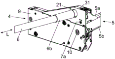
Fig. 1a shows a piece of furniture 1 comprising a furniture body 2 and a movable furniture part 3 in the form of a furniture flap 3a which is liftable relative to the furniture body 2. A furniture drive 4 for moving the movable furniture part 3 is fastened to the opposite side walls of the furniture carcass 2. The furniture drive 4 has in each case one actuating arm 5 which is rotatably mounted, wherein the rotational movements of the two actuating arms 5 of the furniture drive 4 can be synchronized with one another by a synchronization shaft 6.
Fig. 1b shows the piece of furniture 1 according to fig. 1a with the furniture part 3 removed. The two furniture drives 4 can be configured identically, so that the explanations listed here apply to the two furniture drives 4 in each case.
The furniture drive 4 has a preferably substantially right-angled hexagonal support 9 to be fastened to the furniture body 2, on which support at least one lever 5a of the actuating arm 5 is pivotally mounted about a first rotational axis 7 a. While the synchronizing shaft 6 is rotatably supported about a second rotation axis 7b, wherein the first rotation axis 7a of the lever 5a and the second rotation axis 7b of the synchronizing shaft 6 are laterally offset from each other, preferably spaced apart parallel to each other.
The offset arrangement between the first rotation axis 7a of the lever 5a of the actuating arm 5 and the second rotation axis 7b of the synchronization shaft 6 has the special advantage that the synchronization shaft 6 can be arranged, for example, at a high position in the furniture carcass 2, i.e. close to the top 2a of the furniture carcass 2.
Furthermore, it can be provided that the second rotary shaft 7b can be arranged deeper in the depth direction of the furniture carcass 2 in the assembled state of the furniture carcass 4 than in the case of the coaxial arrangement between the first rotary shaft 7a and the second rotary shaft 7b known from the prior art.
The lever 5a of the actuating arm 5 has a fitting 8 which can be detachably connected to a fitting body (not shown) to be fastened to the furniture part 3. The fitting 8 can be connected to the lever 5a of the actuating arm 5 in an articulated manner and can be designed such that the fitting 8 can be connected to the fitting body to be fastened to the furniture part 3 in a tool-free manner.
Fig. 2a-2c show the assembly of the synchronization shaft 6 on the furniture drive 4. The actuator arm 5 may have a plurality of mutually articulated bars 5a, 5b, preferably:
at least two of the provided levers 5a, 5b of the actuator arm 5 are arranged nested within one another in at least one, preferably in each, rotational position of the actuator arm 5, such that the two levers 5a, 5b are configured essentially without play from one another in a top view from the side, and/or
At least one rod 5b is formed in a U-shape in cross section and the other rod 5a is arranged or can be arranged at least partially between the vertical sections of the U-shape, and/or
The actuator arm 5 is designed symmetrically about an imaginary central plane, and/or
At least one, preferably at least two, of the levers 5a, 5b of the actuator arm 5 can be detachably connected to a bracket 9 of the furniture drive 4.
In the embodiment shown, the first lever 5a is pivotally supported about a first rotation axis 7a and the other lever 5b is pivotally supported about another rotation axis 10.
The support 9 has at least one upper side 31 which, in the mounted state of the furniture drive 4 on the furniture body 4, faces the top 2a of the furniture body 2, wherein the first rotation axis 7a has a greater vertical distance from the at least one upper side 31 than the second rotation axis 7b (fig. 1 b).
The furniture drive 4 comprises an interface 21 for fastening a synchronizing shaft 6, by means of which the rotational movement of the at least one actuator arm 5 can be synchronized with the rotational movement of the at least one actuator arm 5 of the at least one further furniture drive 4.
The interface 21 comprises a member 11 rotatably supported about the second rotation axis 7b, which member can be detachably connected with the synchronization shaft 6. It can be seen that the first rotation axis 7a of the rod 5a and the second rotation axis 7b of the member 11 are spaced apart parallel to each other.
The member 11 rotatable about the second rotation axis 7b has receiving means 11a for receiving the synchronizing shaft 6. Preferably, the receiving means 11a have a non-circular cross section for receiving the synchronization shaft 6. In a particularly preferred manner, the synchronization shaft 6 is connectable to the receiving device 11a only in a single rotational position within a rotational angle range of 360 °.
The synchronizing shaft 6 has a journal 6a, the outer contour of which essentially corresponds to the inner contour of the receiving means 11a. In this way, a positive-locking connection for transmitting torque between the rotatable component 11 and the synchronization shaft 6 can be established.
Starting from fig. 2a, the journal 6a of the synchronization shaft 6 is introduced into a receptacle 11a of the rotatable component 11 (fig. 2 b). The cover part 6b, which is movable in the direction of the longitudinal axis (L), is then pushed into the receiving device 11a, wherein the shaft journal 6a can be covered (fig. 2 c).
The first furniture drive 4 is fastened to a first side wall of the furniture body 2 and the second furniture drive 4 is fastened to a second side wall of the furniture body 2 opposite the first side wall.
The synchronizing shaft 6 is connected in an assembled state to two rotatably mounted components 11 of the furniture drive 4 in a rotationally fixed manner, wherein a rotational movement of the at least one actuating arm 5 of the first furniture drive 4 and a rotational movement of the at least one actuating arm 5 of the second furniture drive 4 can be synchronized by the synchronizing shaft 6.
Fig. 3a shows an exploded view of the synchronization shaft 6. The synchronizing shaft 6 comprises an intermediate shaft member 6g, which may have a non-rotationally symmetrical cross section.
The connecting piece 6f is connectable to a first end region of the shaft element 6g, wherein the connecting piece 6f is designed to receive a spring element 6d. The pin 6a is formed on a part 6c that can be acted upon by a spring element 6d, wherein the pin 6a is pressed against the rotatable component 11 by the spring element 6d in the assembled state of the synchronization shaft 6.
The portion 6c is blocked by the limiting element 6e and is disengaged from the connection piece 6 f. At least the axle journal 6a can be covered by a preferably sleeve-shaped cover part 6 b.
The spring element 6d is preferably absent at the second end region of the synchronization shaft 6. In this case, a form-locking connection and a movable cover part 6i for the non-rotatable connection of the synchronization shaft 6 to the rotatable component 11 of the opposite furniture drive 4 are present on the connection piece 6 h.
Fig. 3b shows the synchronization shaft 6 in the assembled state.
Fig. 4a shows a side view of the furniture drive 4. The furniture drive 4 has at least one energy store 12, preferably mounted on a carrier 9, which preferably comprises at least one spring element 12a, by means of which the actuator arm 5 (not shown here) can be acted upon with a force in order to compensate for the weight of the furniture part 3 to be fastened to the actuator arm 5.
The force storable in the energy store 12 can be transmitted to the actuator arm 5 by means of a transmission mechanism 17, preferably the transmission mechanism 17 comprises
At least one intermediate lever 13 pivotable about a rotation axis 13a, preferably the at least one energy store 12 being connected to the at least one intermediate lever 13 via a preferably adjustable application point 14, and/or
At least one pressure piece 15, preferably a rotatable pressure roller, and at least one adjustment contour 16, on which the at least one pressure piece 15 is movably supportable upon movement of the actuator arm 5, preferably the at least one pressure piece 15 is or can be provided on at least one intermediate lever 13 of the transmission mechanism 17 and the at least one adjustment contour 16 is or can be provided on the actuator arm 5, or vice versa.
The interface 21 has the member 11 rotatable about the rotation axis 7b, which member is provided with receiving means 11a for releasably receiving the synchronizing shaft 6.
The furniture drive 4 has at least one coupling device 18, by means of which a rotational movement of the at least one actuator arm 5 can be coupled with a rotational movement of the at least one component 11 of the interface 21. It can be seen that the rotation axis 7a of the actuator arm 5 and the rotation axis 7b of the rotatable member 11 are arranged offset from each other.
According to one embodiment, it can be provided that the at least one coupling device 18 has a non-circular transmission.
The coupling device 18 may have at least one tooth 19, 20, preferably the at least one tooth 19, 20 has at least one tooth sector 19a, 20a (fig. 5a, 5 b).
Fig. 4b shows an enlarged view of the area enclosed in fig. 4a, in which the coupling means 18 for coupling between the actuator arm 5 and the rotatable member 11 are shown in more detail.
Fig. 5a shows an interface 21 for releasably fastening the synchronization shaft 6.
According to one embodiment, it can be provided that the at least one tooth 19, 20 has at least two tooth sectors 19a, 20a, wherein
One of the two sectors 19a is connected or connectable with the at least one actuator arm 5, and the other of the two sectors 20a is connected or connectable with the interface 21, and/or
At least two toothed sectors 19a, 20a are arranged in layers against each other in the direction of the first or second rotation axis 7a, 7 b.
The at least two toothed segments 19a, 20a are arranged in the illustrated illustration in a layered manner against one another in the direction of the first or second rotational axis 7a, 7b, wherein one of the at least two toothed segments 19a, 20a is made of a first material and the other of the toothed segments 19a, 20a is made of a second material, which has a lower hardness than the first material, preferably the first material is steel and/or the second material is plastic.
According to a preferred embodiment of the invention, at least two tooth segments 20a, 20b can be arranged in layers against one another in the direction of the first or second rotational axis 7a, 7b, wherein one tooth segment of the at least two tooth segments 20a, 20b protrudes beyond the other tooth segment 20a of the tooth segments in the radial direction with respect to the first or second rotational axis 7a, 7 b.
In other words, in fig. 5a, at least one preferably elastic plastic middle toothed segment 20a is received between two preferably steel outer toothed segments 20a, wherein the middle toothed segment 20a protrudes beyond the two outer toothed segments 20a in the radial direction. In this way, the play occurring between the teeth 19, 20 of the coupling device 18 can be reduced and the synchronization between the two rotatable components 11 of the furniture drive 4 can be significantly improved.
Fig. 5b shows an exploded view of the teeth 19, 20 that interact with each other.
The teeth 20 are arranged on the rotation shaft 7b of the rotatable member 11 and have a plurality of teeth sectors 20a which abut each other. The toothed segment 20a is of substantially disk-shaped design and is supported by a distance piece 22 on the rotary shaft 7b of the component 11.
And the other tooth 19 is provided on the first rotation shaft 7a of the actuator arm 5.
According to one exemplary embodiment, it can be provided that the at least one tooth 19 has at least one tooth segment 19a, wherein at least one pretensioning element 23 is provided, by means of which the at least one tooth segment 19a can be pressed in a radial direction with respect to the first or second rotational axis 7a, 7b, preferably
The at least one pretensioning element 23 can be configured elastically telescopically or as a mechanical spring element, and/or
The at least one pretensioning element 23 is essentially ring-shaped and/or
The at least one pretensioning element 23 is supported on the first or second rotation shaft 7a, 7b, and/or
At least one guide 26 is provided, wherein the at least one toothed segment 19a is mounted along the guide 26 in a movable, preferably linearly movable manner.
In other words, in fig. 5b, at least one intermediate tooth segment 19a or a plurality of intermediate tooth segments 19a is received between two outer tooth segments 19a, wherein the intermediate tooth segments 19a are pressed radially outwards by the pretensioning element 23, so that the intermediate tooth segments 19a protrude slightly beyond the two outer tooth segments 19a in the radial direction. In this way, the play occurring between the teeth 19, 20 of the coupling device 18 can be reduced and the synchronization between the two rotatable components 11 of the two furniture drives 4 can be improved.
At least one tooth 19a of the outer tooth segment may have a guide 26 for movably supporting the middle tooth segment 19 a.
For example, it can be provided that the at least one middle tooth flank 19a, 20a protrudes beyond the two outer tooth flanks 19a, 20a by between 0.01mm and 0.1mm, preferably between 0.03mm and 0.07 mm.
At least one tooth 19, 20 may have a connection means 27 for releasably connecting the bars 5a, 5b of the actuator arm 5. The connecting device 27 may, for example, have at least one recess 27a for receiving the rod 5a, 5b of the actuator arm 5 locally.
By means of the unlocking element 24, which is prestressed by the spring 25, one lever 5a, 5b of the actuating arm 5 can be unlocked starting from the state of connection to the support 9, preferably from the state of connection to the teeth 19, 20. In this way, the actuator arm 5 can be separated from the bracket 9. By actuating the unlocking element 24 against the force of the spring 25, the locking between the actuating arm 5 and the teeth 19, 20 can be released.
Fig. 6a shows the lever 5a of the actuator arm 5 to be connected to the bracket 9. The tooth 19, preferably the tooth sector 19a, has at least one preferably funnel-shaped recess 27a for receiving the rod 5a in places. It can be seen that the contour of the recess 27a is adapted at least in sections to the contour of the rod 5a, wherein the rod 5a engages in a form-locking manner in the recess 27a in the connected state.
The lever 5a is suspended by a first recess 28a from a first locking element provided on the first rotary shaft 7 a. When the rod 5a is pushed into the recess 27a, the second locking element 29 moves along the guide track 30 counter to the force of the spring 25 by co-action with the rod 5a. A locking element 29a, for example a pin protruding laterally from the lever 5a, is provided on the lever 5a, wherein the locking element 29a engages in a further recess 29b in the connected state of the lever 5a. The locking of the lever 5a is established by a locking element 29 which can be locked into a second recess 28b of the lever 5a by the force of a spring 25 (fig. 6 b).
A particularly rotationally locked connection of the lever 5a with respect to the support 9 can be established by means of a three-point locking (recess 28a on the rotary shaft 7a, locking element 29a in recess 27b, locking element 29 in recess 28 b).
The recess 27a of the tooth 19 can form an insertion funnel for insertion into the rod 5a of the actuator arm 5, whereby the rod 5a can be centered in the direction of the rotation axis 7a during assembly.
In order to release the locking between the lever 5a and the support 9, the unlocking element 24 is moved against the force of the spring 25 until the second locking element 29 can be unlocked from the second recess 28b of the lever 5a.
Claims (16)
1. Furniture drive (4) for moving a movably supported furniture part (3), comprising:
a bracket (9) for fastening to the furniture body (2),
at least one actuating arm (5) which can be rotated about at least one first rotation axis (7 a) for moving the movably supported furniture part (3) relative to the support (9),
an interface (21) for fastening a synchronization shaft (6), wherein the rotational movement of the at least one actuator arm (5) can be synchronized with the rotational movement of the at least one actuator arm (5) of the at least one further furniture drive (4) by means of the synchronization shaft (6),
the interface (21) has at least one component (11) which can rotate about a second axis of rotation (7 b), the second axis of rotation (7 b) being arranged laterally offset with respect to the first axis of rotation (7 a) of the actuator arm (5),
characterized in that the support (9) has at least one upper side (31) which, in the assembled state of the furniture drive (4) on the furniture body (4), faces the top (2 a) of the furniture body (2), the first rotation axis (7 a) being at a greater vertical distance from the at least one upper side (31) than the second rotation axis (7 b).
2. Furniture drive (4) according to claim 1, characterized in that the bracket (9) has at least one end side through which the at least one actuating arm (5) passes at least in sections at least in a relative position corresponding to the open position of the movable furniture part (3), wherein the first rotation axis (7 a) has a smaller vertical distance from the at least one end side than the second rotation axis (7 b).
3. Furniture drive (4) according to claim 1 or 2, characterized in that at least one coupling device (18) is provided, by means of which a rotational movement of the at least one actuator arm (5) can be coupled with a rotational movement of the at least one component (11) of the interface (21).
4. A furniture drive (4) according to claim 3, characterized in that the at least one coupling means (18) has a non-circular transmission.
5. Furniture drive (4) according to claim 3 or 4, characterized in that the at least one coupling device (18) has at least one tooth (19, 20), preferably the at least one tooth (19, 20) has at least one tooth segment (19 a, 20 a).
6. Furniture drive (4) according to claim 5, characterized in that the at least one tooth (19, 20) has at least one tooth segment (19 a, 20 a), wherein the tooth segment (19 a, 20 a) has a connecting means (27) for releasably connecting the lever (5 a, 5 b) of the actuating arm (5), preferably the connecting means (27) has at least one recess (27 a) for locally receiving the lever (5 a, 5 b) of the actuating arm (5).
7. Furniture drive (4) according to claim 5 or 6, wherein the at least one tooth (19, 20) has at least two tooth sectors (19 a, 20 a), wherein
-one of the two sectors (19 a, 20 a) is connected or connectable with the at least one actuator arm (5), and the other of the two sectors (19 a, 20 a) is connected or connectable with the interface (21), and/or
-at least two tooth sectors (19 a, 20 a) are arranged layer-wise against each other in the direction of the first or second rotation axis (7 a, 7 b).
8. Furniture drive (4) according to one of the claims 5 to 7, characterized in that the at least one tooth (19, 20) has at least one tooth segment (19 a, 20 a), wherein at least one pretensioning element (23) is provided, by means of which the at least one tooth segment (19 a, 20 a) can be pressed in a radial direction with respect to the first or second rotational axis (7 a, 7 b), preferably
-the at least one pretensioning element (23) is configured as a spring element that is elastically stretchable or mechanically, and/or
-said at least one pretensioning element (23) is essentially annular in shape, and/or
-said at least one pretensioning element (23) is supported on the first or second rotation shaft (7 a, 7 b), and/or
-at least one guide (26) is provided, wherein the at least one toothed segment (19 a, 20 a) is mounted so as to be movable, preferably linearly movable, along the guide (26).
9. Furniture drive (4) according to claim 7 or 8, characterized in that at least two tooth segments (19 a, 20 a) are arranged layer by layer against each other in the direction of the first or second rotational axis (7 a, 7 b), wherein one of the at least two tooth segments (19 a, 20 a) is made of a first material and the other tooth segment (19 a, 20 a) is made of a second material, which has a lower hardness than the first material, preferably the first material is steel and/or the second material is plastic.
10. Furniture drive (4) according to one of the claims 7 to 9, characterized in that at least two tooth sectors (19 a, 20 a) are arranged in layers against each other in the direction of the first or second rotational axis (7 a, 7 b), wherein one tooth sector of the at least two tooth sectors (19 a, 20 a) protrudes in the radial direction from the other tooth sector of the tooth sectors (19 a, 20 a) with respect to the first or second rotational axis (7 a, 7 b).
11. Furniture drive (4) according to one of claims 1 to 10, characterized in that the member (11) rotatable about the second rotational axis (7 b) has a receiving means (11 a) for receiving the synchronization shaft (6), preferably the receiving means (11 a) has a non-circular cross section for receiving the synchronization shaft (6), particularly preferably the synchronization shaft (6) can be connected to the receiving means (11 a) only in a single rotational position within a rotational angle range of 360 °.
12. Furniture drive (4) according to one of claims 1 to 11, characterized in that the actuating arm (5) has a plurality of mutually articulated rods (5 a, 5 b), preferably
-at least two of the provided bars (5 a, 5 b) of the actuator arm (5) are provided nested within each other in at least one, preferably each, rotational position of the actuator arm (5) such that the two bars (5 a, 5 b) are configured substantially without gaps from each other in a top view seen from the side, and/or
-at least one rod (5 b) is U-shaped in cross section and the other rod (5 a) is at least partially arranged or can be arranged between the vertical segments of the U-shape, and/or
-the actuator arm (5) is symmetrically configured with respect to an imaginary central plane, and/or
-at least one, preferably at least two, of the levers (5 a, 5 b) of the actuator arm (5) can be detachably connected with a bracket (9) of a furniture drive (4).
13. Furniture drive (4) according to one of claims 1 to 12, wherein the furniture drive (4) has at least one energy store (12), preferably supported on a carrier (9), which preferably comprises at least one spring element (12 a), by means of which the actuating arm (5) can be acted upon in order to compensate for the weight of the furniture part (3) to be fastened to the actuating arm (5).
14. Furniture drive (4) according to claim 13, wherein a transmission mechanism (17) is provided, with which force storable in the at least one energy store (12) can be transmitted to the actuator arm (5), preferably the transmission mechanism (17)
-comprising at least one intermediate lever (13) pivotable about a rotation axis (13 a), preferably the at least one accumulator (12) being connected to the at least one intermediate lever (13) by means of a preferably adjustable action site (14), and/or
-comprising at least one pressure piece (15), preferably a rotatable pressure roller, and at least one adjustment contour (16), on which the at least one pressure piece (15) can be movably supported when the actuator arm (5) is moved, preferably the at least one pressure piece (15) is arranged or can be arranged on at least one intermediate lever (13) of the transmission mechanism (17) and the at least one adjustment contour (16) is arranged or can be arranged on the actuator arm (5), or the at least one adjustment contour is arranged or can be arranged on at least one intermediate lever of the transmission mechanism and the at least one pressure piece is arranged or can be arranged on the actuator arm.
15. Arrangement comprising a first furniture drive (4) according to one of claims 1 to 14, a second furniture drive (4) according to one of claims 1 to 14, and a synchronization shaft (6), wherein the first furniture drive (4) can be fastened to a first side wall of the furniture body (2) and the second furniture drive (4) can be fastened to a second side wall of the furniture body (2) opposite the first side wall, wherein the synchronization shaft (6) is connected in an assembled state in a rotationally fixed manner to two rotatably mounted components (11) of the furniture drive (4), and a rotational movement of the at least one actuating arm (5) of the first furniture drive (4) can be synchronized with a rotational movement of the at least one actuating arm (5) of the second furniture drive (4) by means of the synchronization shaft (6).
16. Arrangement according to claim 15, characterized in that the synchronization shaft (6) has a spring-loaded part (6 c) on at least one end region, which can be brought into abutment against a rotatably mounted component (11) of the furniture drive (4).
Applications Claiming Priority (3)
| Application Number | Priority Date | Filing Date | Title |
|---|---|---|---|
| ATA50912/2020A AT524338B1 (en) | 2020-10-22 | 2020-10-22 | furniture drive |
| ATA50912/2020 | 2020-10-22 | ||
| PCT/AT2021/060380 WO2022082237A1 (en) | 2020-10-22 | 2021-10-15 | Furniture drive |
Publications (1)
| Publication Number | Publication Date |
|---|---|
| CN116420003A true CN116420003A (en) | 2023-07-11 |
Family
ID=78463313
Family Applications (1)
| Application Number | Title | Priority Date | Filing Date |
|---|---|---|---|
| CN202180070842.2A Pending CN116420003A (en) | 2020-10-22 | 2021-10-15 | Furniture driving device |
Country Status (6)
| Country | Link |
|---|---|
| US (1) | US20230340818A1 (en) |
| EP (1) | EP4232673A1 (en) |
| JP (1) | JP2023547147A (en) |
| CN (1) | CN116420003A (en) |
| AT (1) | AT524338B1 (en) |
| WO (1) | WO2022082237A1 (en) |
Families Citing this family (1)
| Publication number | Priority date | Publication date | Assignee | Title |
|---|---|---|---|---|
| AT17927U1 (en) * | 2022-05-13 | 2023-08-15 | Blum Gmbh Julius | Synchronization device for moving a movable furniture part |
Family Cites Families (7)
| Publication number | Priority date | Publication date | Assignee | Title |
|---|---|---|---|---|
| AT502937B1 (en) | 2005-04-28 | 2013-06-15 | Blum Gmbh Julius | CABINET FURNITURE |
| AT506642B1 (en) * | 2008-03-17 | 2014-03-15 | Blum Gmbh Julius | STAGE ASSEMBLY WITH TWO ADJUSTING DEVICES |
| AT508959B1 (en) * | 2009-10-23 | 2012-06-15 | Blum Gmbh Julius | SYNCHRONIZATION DEVICE FOR SYNCHRONIZING TWO ACTUATORS FOR MOVING A MOVABLE FURNITURE PART |
| JP5415491B2 (en) * | 2011-07-29 | 2014-02-12 | スガツネ工業株式会社 | Door opening / closing device unit and method of mounting the door opening / closing device unit |
| AT511335B1 (en) * | 2011-09-20 | 2012-11-15 | Blum Gmbh Julius | SYNCHRONIZATION DEVICE FOR MOVING FURNITURE PARTS |
| AT516783B1 (en) * | 2015-02-13 | 2017-05-15 | Blum Gmbh Julius | Support device for a furniture flap |
| CN106639718B (en) * | 2017-01-11 | 2018-04-06 | 伍志勇 | A kind of synchronous upset mechanism for opening/closing for furniture |
-
2020
- 2020-10-22 AT ATA50912/2020A patent/AT524338B1/en active
-
2021
- 2021-10-15 US US18/027,542 patent/US20230340818A1/en active Pending
- 2021-10-15 WO PCT/AT2021/060380 patent/WO2022082237A1/en active Application Filing
- 2021-10-15 CN CN202180070842.2A patent/CN116420003A/en active Pending
- 2021-10-15 JP JP2023524696A patent/JP2023547147A/en active Pending
- 2021-10-15 EP EP21800987.6A patent/EP4232673A1/en active Pending
Also Published As
| Publication number | Publication date |
|---|---|
| JP2023547147A (en) | 2023-11-09 |
| EP4232673A1 (en) | 2023-08-30 |
| AT524338B1 (en) | 2023-08-15 |
| US20230340818A1 (en) | 2023-10-26 |
| WO2022082237A1 (en) | 2022-04-28 |
| AT524338A1 (en) | 2022-05-15 |
Similar Documents
| Publication | Publication Date | Title |
|---|---|---|
| CN116420003A (en) | Furniture driving device | |
| KR101860621B1 (en) | Drive device for a movable furniture part | |
| ITAL990009A1 (en) | ARTICULATED ACTUATOR FOR GATES, DOORS AND SIMILAR. | |
| CA2745609C (en) | Furniture hinge with rotation damper | |
| CN102858205B (en) | Locking accessory | |
| JP6611828B2 (en) | Furniture hinges | |
| RU2531879C2 (en) | Actuator drive for mobile part of furniture | |
| JP2021042667A (en) | Operation arm driving device | |
| US9543804B2 (en) | Electric linear drive, in particular for adjusting furniture used for sitting or lying down | |
| US9303739B2 (en) | Linear drive for furniture | |
| EP2017127A1 (en) | Device to adjust the orientation of a mirror of a motorcar | |
| JP2014501591A (en) | Drawer coupling device | |
| MX2011002901A (en) | Motor vehicle lock. | |
| CN204608575U (en) | Vibrator | |
| CN102573743A (en) | Patient lift and coupling therefor | |
| RU2505655C2 (en) | Fittings with drive | |
| CN110114544A (en) | Assembly for moving one or more coplanar doors of a piece of furniture and piece of furniture comprising such an assembly | |
| EP2196835B1 (en) | Load suspension stand and microscopy system | |
| JP2020534095A (en) | Drive device for movable furniture parts | |
| JP2023547143A (en) | furniture drive | |
| CN106460432B (en) | Bearing assembly for door | |
| EP0814226A1 (en) | Device for the adjustable connection of a sliding door wing to a furniture piece | |
| CN208993518U (en) | A kind of locking system that precision is controllable | |
| CN102844514B (en) | Hinge | |
| EP1579786A1 (en) | Arrangement for adjusting a back rest |
Legal Events
| Date | Code | Title | Description |
|---|---|---|---|
| PB01 | Publication | ||
| PB01 | Publication | ||
| SE01 | Entry into force of request for substantive examination | ||
| SE01 | Entry into force of request for substantive examination |