CN116326184A - Method and apparatus for performing DRX operation for each power saving mode in NR V2X - Google Patents
Method and apparatus for performing DRX operation for each power saving mode in NR V2X Download PDFInfo
- Publication number
- CN116326184A CN116326184A CN202180059594.1A CN202180059594A CN116326184A CN 116326184 A CN116326184 A CN 116326184A CN 202180059594 A CN202180059594 A CN 202180059594A CN 116326184 A CN116326184 A CN 116326184A
- Authority
- CN
- China
- Prior art keywords
- side link
- drx
- configuration information
- drx configuration
- link
- Prior art date
- Legal status (The legal status is an assumption and is not a legal conclusion. Google has not performed a legal analysis and makes no representation as to the accuracy of the status listed.)
- Pending
Links
- 238000000034 method Methods 0.000 title claims abstract description 107
- 238000004891 communication Methods 0.000 claims abstract description 141
- 230000015654 memory Effects 0.000 claims description 52
- 230000007704 transition Effects 0.000 claims description 26
- 239000010410 layer Substances 0.000 description 62
- 230000005540 biological transmission Effects 0.000 description 36
- 230000006870 function Effects 0.000 description 23
- 238000005516 engineering process Methods 0.000 description 19
- 230000008569 process Effects 0.000 description 16
- 238000012545 processing Methods 0.000 description 14
- 238000013468 resource allocation Methods 0.000 description 9
- 238000013473 artificial intelligence Methods 0.000 description 5
- 238000013507 mapping Methods 0.000 description 5
- 230000011664 signaling Effects 0.000 description 4
- 238000012546 transfer Methods 0.000 description 4
- 125000004122 cyclic group Chemical group 0.000 description 3
- 238000001514 detection method Methods 0.000 description 3
- 230000000737 periodic effect Effects 0.000 description 3
- 238000012384 transportation and delivery Methods 0.000 description 3
- 230000006978 adaptation Effects 0.000 description 2
- 230000003190 augmentative effect Effects 0.000 description 2
- 230000008859 change Effects 0.000 description 2
- 238000010586 diagram Methods 0.000 description 2
- 230000000694 effects Effects 0.000 description 2
- 230000000977 initiatory effect Effects 0.000 description 2
- 230000007774 longterm Effects 0.000 description 2
- 238000010295 mobile communication Methods 0.000 description 2
- 239000004984 smart glass Substances 0.000 description 2
- 230000027311 M phase Effects 0.000 description 1
- 230000003044 adaptive effect Effects 0.000 description 1
- 238000003491 array Methods 0.000 description 1
- 230000015572 biosynthetic process Effects 0.000 description 1
- 230000001413 cellular effect Effects 0.000 description 1
- 230000006835 compression Effects 0.000 description 1
- 238000007906 compression Methods 0.000 description 1
- 239000000470 constituent Substances 0.000 description 1
- 238000012937 correction Methods 0.000 description 1
- 239000000446 fuel Substances 0.000 description 1
- GVVPGTZRZFNKDS-JXMROGBWSA-N geranyl diphosphate Chemical compound CC(C)=CCC\C(C)=C\CO[P@](O)(=O)OP(O)(O)=O GVVPGTZRZFNKDS-JXMROGBWSA-N 0.000 description 1
- PCHJSUWPFVWCPO-UHFFFAOYSA-N gold Chemical group [Au] PCHJSUWPFVWCPO-UHFFFAOYSA-N 0.000 description 1
- 238000005286 illumination Methods 0.000 description 1
- 230000010354 integration Effects 0.000 description 1
- 239000002346 layers by function Substances 0.000 description 1
- 238000007726 management method Methods 0.000 description 1
- 239000011159 matrix material Substances 0.000 description 1
- 238000005259 measurement Methods 0.000 description 1
- 230000010363 phase shift Effects 0.000 description 1
- 230000004044 response Effects 0.000 description 1
- 230000000630 rising effect Effects 0.000 description 1
- 230000011218 segmentation Effects 0.000 description 1
- 238000010187 selection method Methods 0.000 description 1
- 230000008054 signal transmission Effects 0.000 description 1
- 230000004617 sleep duration Effects 0.000 description 1
- 230000004622 sleep time Effects 0.000 description 1
- 238000001228 spectrum Methods 0.000 description 1
- 238000005406 washing Methods 0.000 description 1
Images


Classifications
-
- H—ELECTRICITY
- H04—ELECTRIC COMMUNICATION TECHNIQUE
- H04W—WIRELESS COMMUNICATION NETWORKS
- H04W4/00—Services specially adapted for wireless communication networks; Facilities therefor
- H04W4/30—Services specially adapted for particular environments, situations or purposes
- H04W4/40—Services specially adapted for particular environments, situations or purposes for vehicles, e.g. vehicle-to-pedestrians [V2P]
-
- H—ELECTRICITY
- H04—ELECTRIC COMMUNICATION TECHNIQUE
- H04W—WIRELESS COMMUNICATION NETWORKS
- H04W4/00—Services specially adapted for wireless communication networks; Facilities therefor
- H04W4/70—Services for machine-to-machine communication [M2M] or machine type communication [MTC]
-
- H—ELECTRICITY
- H04—ELECTRIC COMMUNICATION TECHNIQUE
- H04W—WIRELESS COMMUNICATION NETWORKS
- H04W52/00—Power management, e.g. TPC [Transmission Power Control], power saving or power classes
- H04W52/02—Power saving arrangements
- H04W52/0209—Power saving arrangements in terminal devices
- H04W52/0212—Power saving arrangements in terminal devices managed by the network, e.g. network or access point is master and terminal is slave
- H04W52/0216—Power saving arrangements in terminal devices managed by the network, e.g. network or access point is master and terminal is slave using a pre-established activity schedule, e.g. traffic indication frame
-
- H—ELECTRICITY
- H04—ELECTRIC COMMUNICATION TECHNIQUE
- H04W—WIRELESS COMMUNICATION NETWORKS
- H04W52/00—Power management, e.g. TPC [Transmission Power Control], power saving or power classes
- H04W52/02—Power saving arrangements
- H04W52/0209—Power saving arrangements in terminal devices
- H04W52/0225—Power saving arrangements in terminal devices using monitoring of external events, e.g. the presence of a signal
- H04W52/0229—Power saving arrangements in terminal devices using monitoring of external events, e.g. the presence of a signal where the received signal is a wanted signal
-
- H—ELECTRICITY
- H04—ELECTRIC COMMUNICATION TECHNIQUE
- H04W—WIRELESS COMMUNICATION NETWORKS
- H04W52/00—Power management, e.g. TPC [Transmission Power Control], power saving or power classes
- H04W52/02—Power saving arrangements
- H04W52/0209—Power saving arrangements in terminal devices
- H04W52/0251—Power saving arrangements in terminal devices using monitoring of local events, e.g. events related to user activity
-
- H—ELECTRICITY
- H04—ELECTRIC COMMUNICATION TECHNIQUE
- H04W—WIRELESS COMMUNICATION NETWORKS
- H04W72/00—Local resource management
- H04W72/20—Control channels or signalling for resource management
- H04W72/25—Control channels or signalling for resource management between terminals via a wireless link, e.g. sidelink
-
- H—ELECTRICITY
- H04—ELECTRIC COMMUNICATION TECHNIQUE
- H04W—WIRELESS COMMUNICATION NETWORKS
- H04W76/00—Connection management
- H04W76/10—Connection setup
- H04W76/14—Direct-mode setup
-
- H—ELECTRICITY
- H04—ELECTRIC COMMUNICATION TECHNIQUE
- H04W—WIRELESS COMMUNICATION NETWORKS
- H04W76/00—Connection management
- H04W76/20—Manipulation of established connections
- H04W76/28—Discontinuous transmission [DTX]; Discontinuous reception [DRX]
-
- H—ELECTRICITY
- H04—ELECTRIC COMMUNICATION TECHNIQUE
- H04W—WIRELESS COMMUNICATION NETWORKS
- H04W92/00—Interfaces specially adapted for wireless communication networks
- H04W92/16—Interfaces between hierarchically similar devices
- H04W92/18—Interfaces between hierarchically similar devices between terminal devices
-
- H—ELECTRICITY
- H04—ELECTRIC COMMUNICATION TECHNIQUE
- H04W—WIRELESS COMMUNICATION NETWORKS
- H04W76/00—Connection management
- H04W76/20—Manipulation of established connections
- H04W76/27—Transitions between radio resource control [RRC] states
-
- Y—GENERAL TAGGING OF NEW TECHNOLOGICAL DEVELOPMENTS; GENERAL TAGGING OF CROSS-SECTIONAL TECHNOLOGIES SPANNING OVER SEVERAL SECTIONS OF THE IPC; TECHNICAL SUBJECTS COVERED BY FORMER USPC CROSS-REFERENCE ART COLLECTIONS [XRACs] AND DIGESTS
- Y02—TECHNOLOGIES OR APPLICATIONS FOR MITIGATION OR ADAPTATION AGAINST CLIMATE CHANGE
- Y02D—CLIMATE CHANGE MITIGATION TECHNOLOGIES IN INFORMATION AND COMMUNICATION TECHNOLOGIES [ICT], I.E. INFORMATION AND COMMUNICATION TECHNOLOGIES AIMING AT THE REDUCTION OF THEIR OWN ENERGY USE
- Y02D30/00—Reducing energy consumption in communication networks
- Y02D30/70—Reducing energy consumption in communication networks in wireless communication networks
Abstract
A method of operation of a first device (100) in a wireless communication system is presented. The method may comprise the steps of: establishing a Side Link (SL) unicast link with the second device (200); transmitting first SL Discontinuous Reception (DRX) configuration information related to the SL unicast link to the second device (200); transmitting a physical side link control channel (PSCCH) to the second device (200) in an on-duration interval included in the first SL DRX configuration information; and transmitting a physical side link shared channel (PSSCH) to the second device (200) based on the PSCCH in the on duration interval.
Description
Technical Field
The present disclosure relates to wireless communication systems.
Background
Side Link (SL) communication is a communication scheme in which a direct link is established between User Equipments (UEs) and the UEs exchange voice and data directly with each other without intervention of an evolved node B (eNB). SL communication is being considered as a solution for eNB overhead due to the rapid growth of data traffic. V2X (vehicle to everything) refers to a communication technology in which vehicles are used to exchange information with other vehicles, pedestrians, objects equipped with infrastructure, and the like. V2X can be classified into four types such as V2V (vehicle-to-vehicle), V2I (vehicle-to-infrastructure), V2N (vehicle-to-network), and V2P (vehicle-to-pedestrian). V2X communication may be provided through a PC5 interface and/or Uu interface.
Furthermore, as more and more communication devices require larger communication capacity, the need for enhanced mobile broadband communication relative to conventional Radio Access Technologies (RATs) is rising. Thus, communication system designs for UEs or services that are sensitive to reliability and delay have also been discussed. Also, next generation radio access technologies based on enhanced mobile broadband communication, large-scale Machine Type Communication (MTC), ultra-reliable low latency communication (URLLC), etc. may be referred to as new RATs (radio access technologies) or NR (new radios). Herein, NR may also support vehicle-to-everything (V2X) communication.
Fig. 1 is a diagram for describing NR based V2X communication compared to V2X communication based on RAT used before NR. The embodiment of fig. 1 may be combined with various embodiments of the present disclosure.
Regarding V2X communication, when discussing RATs used before NR, a scheme of providing security services based on V2X messages such as BSM (basic security message), CAM (cooperative awareness message), and DENM (distributed environment notification message) is focused. The V2X message may include location information, dynamic information, attribute information, and the like. For example, the UE may send a periodic message type CAM and/or an event trigger message type denom to another UE.
Thereafter, regarding V2X communication, various V2X scenes are proposed in NR. For example, such various V2X scenarios may include vehicle formation, advanced driving, extension sensors, remote driving, and the like.
Disclosure of Invention
Technical proposal
In one embodiment, a method of operating a first device 100 in a wireless communication system is presented. The method may include: establishing a Side Link (SL) unicast link with the second device 200; transmitting first SL Discontinuous Reception (DRX) configuration information related to the SL unicast link to the second device 200; transmitting a physical side link control channel (PSCCH) to the second device 200 in an on duration interval included in the first SL DRX configuration information; in the on duration interval, a physical side link shared channel (PSSCH) is transmitted to the second device 200 based on the PSCCH.
Advantageous effects
A User Equipment (UE) can efficiently perform SL communication.
Drawings
Fig. 1 is a diagram for describing NR based V2X communication compared to V2X communication based on RAT used before NR.
Fig. 2 shows a structure of an NR system according to an embodiment of the present disclosure.
Fig. 3 illustrates a radio protocol architecture according to an embodiment of the present disclosure.
Fig. 4 shows a structure of a radio frame of NR according to an embodiment of the present disclosure.
Fig. 5 illustrates a structure of a slot of an NR frame according to an embodiment of the present disclosure.
Fig. 6 illustrates an example of BWP according to an embodiment of the present disclosure.
Fig. 7 illustrates a UE performing V2X or SL communication according to an embodiment of the present disclosure.
Fig. 8 illustrates a process of performing V2X or SL communication by a UE based on a transmission mode according to an embodiment of the present disclosure.
Fig. 9 illustrates three broadcast types according to an embodiment of the present disclosure.
Fig. 10 illustrates a procedure in which UE 1 and UE 2 perform a side link DRX operation in a PC5 idle mode according to an embodiment of the present disclosure.
Fig. 11 illustrates a procedure in which UE 1 and UE 2 perform a side link DRX operation in a PC5 active mode according to an embodiment of the present disclosure.
Fig. 12 illustrates a process in which UE 1 and UE 2 switch power save modes from PC5 active mode to PC5 idle mode in accordance with an embodiment of the present disclosure.
Fig. 13 illustrates a process of performing wireless communication by a first device according to an embodiment of the present disclosure.
Fig. 14 illustrates a process in which a second device performs wireless communication according to an embodiment of the present disclosure.
Fig. 15 shows a communication system 1 according to an embodiment of the present disclosure.
Fig. 16 illustrates a wireless device in accordance with an embodiment of the present disclosure.
Fig. 17 illustrates a signal processing circuit for transmitting a signal according to an embodiment of the present disclosure.
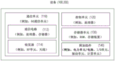
Fig. 18 illustrates another example of a wireless device in accordance with an embodiment of the present disclosure.
Fig. 19 illustrates a handheld device in accordance with an embodiment of the present disclosure.
Fig. 20 illustrates a vehicle or autonomous vehicle in accordance with an embodiment of the present disclosure.
Detailed Description
In this disclosure, "a or B" may mean "a only", "B only" or "both a and B". In other words, in the present disclosure, "a or B" may be interpreted as "a and/or B". For example, in this disclosure, "A, B or C" may mean any combination of "a only", "B only", "C only" or "A, B, C".
A slash (/) or comma as used in this disclosure may mean "and/or". For example, "A/B" may mean "A and/or B". Thus, "a/B" may mean "a only", "B only" or "both a and B". For example, "A, B, C" may mean "A, B or C".
In the present disclosure, "at least one of a and B" may mean "a only", "B only", or "both a and B". In addition, in the present disclosure, the expression "at least one of a or B" or "at least one of a and/or B" may be interpreted as "at least one of a and B".
In addition, in the present disclosure, "at least one of A, B and C" may mean "a only", "B only", "C only", or "A, B and C in any combination. In addition, "at least one of A, B or C" or "at least one of A, B and/or C" may mean "at least one of A, B and C".
In addition, brackets used in this disclosure may mean "for example". Specifically, when indicated as "control information (PDCCH)", this may mean that "PDCCH" is proposed as an example of "control information". In other words, the "control information" of the present disclosure is not limited to "PDCCH", and "PDCCH" may be proposed as an example of the "control information". Specifically, when indicated as "control information (i.e., PDCCH)", this may also mean that "PDCCH" is proposed as an example of "control information".
The technical features respectively described in a drawing in the present disclosure may be implemented separately or may be implemented simultaneously.
The techniques described below may be used in various wireless communication systems such as Code Division Multiple Access (CDMA), frequency Division Multiple Access (FDMA), time Division Multiple Access (TDMA), orthogonal Frequency Division Multiple Access (OFDMA), single carrier frequency division multiple access (SC-FDMA), etc. CDMA may be implemented using a radio technology such as Universal Terrestrial Radio Access (UTRA) or CDMA-2000. TDMA may be implemented using radio technologies such as global system for mobile communications (GSM)/General Packet Radio Service (GPRS)/enhanced data rates for GSM evolution (EDGE). OFDMA may be implemented using radio technologies such as Institute of Electrical and Electronics Engineers (IEEE) 802.11 (Wi-Fi), IEEE 802.16 (WiMAX), IEEE 802.20, evolved UTRA (E-UTRA), and so on. IEEE 802.16m is an evolving version of IEEE 802.16e and provides backward compatibility for IEEE 802.16 e-based systems. UTRA is part of Universal Mobile Telecommunications System (UMTS). The third generation partnership project (3 GPP) Long Term Evolution (LTE) is part of evolved UMTS (E-UMTS) that uses E-UTRA. The 3GPP LTE uses OFDMA in the downlink and SC-FDMA in the uplink. LTE-advanced (LTE-a) is an evolution of LTE.
The 5G NR is an LTE-a successor technology corresponding to a novel completely new mobile communication system having characteristics of high performance, low latency, high availability, and the like. The 5G NR may use resources including all available frequency spectrums of a low frequency band less than 1GHz, an intermediate frequency band from 1GHz to 10GHz, and a high frequency (millimeter wave) of 24GHz or more, and the like.
For clarity of description, the following description will focus mainly on LTE-a or 5G NR. However, technical features according to embodiments of the present disclosure will not be limited thereto.
Fig. 2 shows a structure of an NR system according to an embodiment of the present disclosure. The embodiment of fig. 2 may be combined with various embodiments of the present disclosure.
Referring to fig. 2, a next generation radio access network (NG-RAN) may include a BS 20 providing user plane and control plane protocol releases to a UE 10. For example, the BS 20 may include a next generation node B (gNB) and/or an evolved node B (eNB). For example, the UE 10 may be fixed or mobile and may be referred to as other terminology such as a Mobile Station (MS), a User Terminal (UT), a Subscriber Station (SS), a Mobile Terminal (MT), a wireless device, etc. For example, a BS may be referred to as a fixed station that communicates with the UEs 10 and may be referred to as other terminology such as a Base Transceiver System (BTS), an Access Point (AP), and the like.
The embodiment of fig. 2 illustrates a case where only the gNB is included. BS 20 may be interconnected via an Xn interface. The BS 20 may be interconnected via a fifth generation (5G) core network (5 GC) and NG interface. More specifically, the BS 20 may be connected to an access and mobility management function (AMF) 30 via an NG-C interface, and may be connected to a User Plane Function (UPF) 30 via an NG-U interface.
The radio interface protocol layers between the UE and the network may be classified into a first layer (L1), a second layer (L2), and a third layer (L3) based on the lower three layers of the Open System Interconnection (OSI) model well known in communication systems. Wherein a Physical (PHY) layer belonging to the first layer provides an information transfer service using a physical channel, and a Radio Resource Control (RRC) layer located at the third layer controls radio resources between the UE and the network. For this, the RRC layer exchanges RRC messages between the UE and the BS layer.
Fig. 3 illustrates a radio protocol architecture in accordance with an embodiment of the present disclosure. The embodiment of fig. 3 may be combined with various embodiments of the present disclosure. Specifically, (a) in fig. 3 shows a radio protocol stack of a user plane for Uu communication, and (b) in fig. 3 shows a radio protocol stack of a control plane for Uu communication. Fig. 3 (c) shows a radio protocol stack of a user plane for SL communication, and fig. 3 (d) shows a radio protocol stack of a control plane for SL communication.
Referring to fig. 3, a physical layer provides an information transfer service to an upper layer through a physical channel. The physical layer is connected to a Medium Access Control (MAC) layer, which is an upper layer of the physical layer, through a transport channel. Data is transferred between the MAC layer and the physical layer through a transfer channel. The transport channels are classified according to how data is transmitted over the radio interface and what characteristics the data is transmitted.
Data is transferred through a physical channel between different physical layers, i.e., a PHY layer of a transmitter and a PHY layer of a receiver. The physical channel may be modulated using an Orthogonal Frequency Division Multiplexing (OFDM) scheme, and uses time and frequency as radio resources.
The MAC layer provides services to a Radio Link Control (RLC) layer, which is a higher layer of the MAC layer, via a logical channel. The MAC layer provides a function of mapping a plurality of logical channels to a plurality of transport channels. The MAC layer also provides a function of logical channel multiplexing by mapping a plurality of logical channels to a single transport channel. The MAC layer provides a data transfer service through a logical channel.
The RLC layer performs concatenation, segmentation and reassembly of radio link control service data units (RLC SDUs). In order to ensure different quality of service (QoS) required for Radio Bearers (RBs), the RLC layer provides three types of operation modes, namely a Transparent Mode (TM), a non-acknowledged mode (UM), and an Acknowledged Mode (AM). AM RLC provides error correction through automatic repeat request (ARQ).
The Radio Resource Control (RRC) layer is defined only in the control plane. The RRC layer serves to control logical channels, transport channels, and physical channels associated with configuration, reconfiguration, and release of RBs. The RB is a logical path for data delivery between the UE and the network provided by the first layer (i.e., physical layer or PHY layer) and the second layer (i.e., MAC layer, RLC layer, packet Data Convergence Protocol (PDCP) layer, and Service Data Adaptation Protocol (SDAP) layer).
The functions of Packet Data Convergence Protocol (PDCP) in the user plane include delivery of user data, header compression, and ciphering. The functions of the Packet Data Convergence Protocol (PDCP) in the control plane include delivery of control plane data and ciphering/integrity protection.
The Service Data Adaptation Protocol (SDAP) layer is defined only in the user plane. The SDAP layer performs a mapping between quality of service (QoS) flows and Data Radio Bearers (DRBs) and QoS Flow ID (QFI) flags in both DL packets and UL packets.
Configuration of the RB means a process for designating a radio protocol layer and channel properties to provide a specific service and for determining corresponding detailed parameters and operation methods. RBs may then be classified into two types, namely, signaling Radio Bearers (SRBs) and Data Radio Bearers (DRBs). The SRB is used as a path for transmitting RRC messages in the control plane, and the DRB is used as a path for transmitting user data in the user plane.
When an RRC connection is established between the RRC layer of the UE and the RRC layer of the E-UTRAN, the UE is in an RRC CONNECTED (rrc_connected) state, otherwise the UE may be in an RRC IDLE (rrc_idle) state. In the case of NR, an RRC inactive (RRC INACTIVE) state is additionally defined, and a UE in RRC INACTIVE state may maintain a connection with the core network and release its connection with the BS.
Downlink transport channels for transmitting (or transmitting) data from a network to a UE include a Broadcast Channel (BCH) for transmitting system information and a downlink Shared Channel (SCH) for transmitting other user traffic or control messages. Traffic or control messages of a downlink multicast or broadcast service may be transmitted via a downlink SCH or may be transmitted via a separate downlink Multicast Channel (MCH). In addition, uplink transport channels for transmitting (or transmitting) data from the UE to the network include a Random Access Channel (RACH) for transmitting an initial control message and an uplink Shared Channel (SCH) for transmitting other user traffic or control messages.
Examples of logical channels belonging to a higher layer of a transport channel and mapped to the transport channel may include a Broadcast Control Channel (BCCH), a Paging Control Channel (PCCH), a Common Control Channel (CCCH), a Multicast Control Channel (MCCH), a Multicast Traffic Channel (MTCH), and the like.
Fig. 4 shows a structure of a radio frame of NR according to an embodiment of the present disclosure. The embodiment of fig. 4 may be combined with various embodiments of the present disclosure.
Referring to fig. 4, in NR, a radio frame may be used to perform uplink and downlink transmission. The radio frame is 10ms in length and may be defined as being made up of two fields (HF). A field may include five 1ms Subframes (SFs). A Subframe (SF) may be divided into one or more slots, and the number of slots within the subframe may be determined according to a subcarrier spacing (SCS). Each slot may include 12 or 14 OFDM (a) symbols according to a Cyclic Prefix (CP).
In case of using the normal CP, each slot may include 14 symbols. In case of using the extended CP, each slot may include 12 symbols. Herein, the symbols may include OFDM symbols (or CP-OFDM symbols) and single carrier-FDMA (SC-FDMA) symbols (or discrete fourier transform spread OFDM (DFT-s-OFDM) symbols).
Table 1 shown below shows the number of symbols (N) per slot according to SCS configuration (u) in case of employing normal CP slot symb ) Number of slots per frame (N frame,u slot ) And the number of slots per subframe (N subframe,u slot )。
TABLE 1
| SCS(15*2 u ) | N slot symb | N frame,u slot | N subframe,u slot |
| 15KHz(u=0) | 14 | 10 | 1 |
| 30KHz(u=1) | 14 | 20 | 2 |
| 60KHz(u=2) | 14 | 40 | 4 |
| 120KHz(u=3) | 14 | 80 | 8 |
| 240KHz(u=4) | 14 | 160 | 16 |
Table 2 shows examples of the number of symbols per slot, the number of slots per frame, and the number of slots per subframe according to SCS in case of using the extended CP.
TABLE 2
| SCS(15*2 u ) | N slot symb | N frame,u slot | N subframe,u slot |
| 60KHz(u=2) | 12 | 40 | 4 |
In an NR system, OFDM (a) parameter sets (e.g., SCS, CP length, etc.) between a plurality of cells integrated into one UE may be configured differently. Thus, the (absolute time) duration (or interval) of a time resource (e.g., a subframe, a slot, or a TTI) consisting of the same number of symbols, collectively referred to as a Time Unit (TU) for simplicity, may be configured differently in the integrated cell.
In the NR, a plurality of parameter sets or SCSs for supporting various 5G services may be supported. For example, in the case of an SCS of 15kHz, a wide range of conventional cellular bands can be supported, and in the case of an SCS of 30kHz/60kHz, dense cities, lower latency, wider carrier bandwidths can be supported. In the case where the SCS is 60kHz or more, in order to overcome the phase noise, a bandwidth of more than 24.25GHz can be used.
The NR frequency bands can be defined as two different types of frequency ranges. Two different types of frequency ranges may be FR1 and FR2. The values of the frequency ranges may be changed (or varied), for example, two different types of frequency ranges may be as shown in table 3 below. Among frequency ranges used in NR systems, FR1 may mean "a range below 6 GHz", and FR2 may mean "a range above 6 GHz", and may also be referred to as millimeter wave (mmW).
TABLE 3
| Frequency range assignment | Corresponding frequency range | Subcarrier spacing (SCS) |
| FR1 | 450MHz–6000MHz | 15、30、60kHz |
| FR2 | 24250MHz–52600MHz | 60、120、240kHz |
As described above, the value of the frequency range in the NR system may be changed (or varied). For example, as shown in table 4 below, FR1 may include a bandwidth in the range of 410MHz to 7125 MHz. More specifically, FR1 may include frequency bands of 6GHz (or 5850, 5900, 5925MHz, etc.) and higher. For example, the frequency bands of 6GHz (or 5850, 5900, 5925MHz, etc.) and higher included in FR1 may include unlicensed frequency bands. The unlicensed frequency band may be used for various purposes, such as for vehicle-specific communications (e.g., autopilot).
TABLE 4
| Frequency range assignment | Corresponding frequency range | Subcarrier spacing (SCS) |
| FR1 | 410MHz–7125MHz | 15、30、60kHz |
| FR2 | 24250MHz–52600MHz | 60、120、240kHz |
Fig. 5 shows a structure of a slot of an NR frame according to an embodiment of the present disclosure. The embodiment of fig. 5 may be combined with various embodiments of the present disclosure.
Referring to fig. 5, a slot includes a plurality of symbols in a time domain. For example, in the case of a normal CP, one slot may include 14 symbols. For example, in the case of the extended CP, one slot may include 12 symbols. Alternatively, in case of the normal CP, one slot may include 7 symbols. However, in the case of the extended CP, one slot may include 6 symbols.
The carrier comprises a plurality of subcarriers in the frequency domain. A Resource Block (RB) may be defined as a plurality of consecutive subcarriers (e.g., 12 subcarriers) in the frequency domain. A bandwidth part (BWP) may be defined as a plurality of consecutive (physical) resource blocks ((P) RBs) in the frequency domain, and the BWP may correspond to one parameter set (e.g., SCS, CP length, etc.). The carrier may include up to N BWP (e.g., 5 BWP). The data communication may be performed via an activated BWP. Each element may be referred to as a Resource Element (RE) in the resource grid, and one complex symbol may be mapped to each element.
Hereinafter, a bandwidth part (BWP) and a carrier will be described in detail.
BWP may be a contiguous set of Physical Resource Blocks (PRBs) within a given parameter set. The PRBs may be selected from a contiguous set of portions of a Common Resource Block (CRB) for a given set of parameters on a given carrier.
For example, the BWP may be at least any one of an active BWP, an initial BWP, and/or a default BWP. For example, the UE may not monitor downlink radio link quality in DL BWP other than active DL BWP on the primary cell (PCell). For example, the UE may not receive a PDCCH, a Physical Downlink Shared Channel (PDSCH), or a channel state information-reference signal (CSI-RS) (excluding RRM) other than the active DL BWP. For example, the UE may not trigger a Channel State Information (CSI) report for the inactive DL BWP. For example, the UE may not transmit a Physical Uplink Control Channel (PUCCH) or a Physical Uplink Shared Channel (PUSCH) outside the active UL BWP. For example, in the downlink case, the initial BWP may be given as a continuous set of RBs (configured by a Physical Broadcast Channel (PBCH)) for a Remaining Minimum System Information (RMSI) control resource set (CORESET). For example, in the case of uplink, the initial BWP may be given by a System Information Block (SIB) for a random access procedure. For example, the default BWP may be configured by a higher layer. For example, the initial value of the default BWP may be the initial DL BWP. To save power, if the UE cannot detect Downlink Control Information (DCI) during a specified period, the UE may switch the active BWP of the UE to a default BWP.
Furthermore, BWP may be defined for SL. The same SL BWP may be used in transmission and reception. For example, the transmitting UE may transmit a SL channel or SL signal on a specific BWP, and the receiving UE may receive the SL channel or SL signal on the specific BWP. In the licensed carrier, the SL BWP may be defined separately from the Uu BWP, and the SL BWP may have configuration signaling separate from the Uu BWP. For example, the UE may receive a configuration for SL BWP from the BS/network. For example, the UE may receive a configuration for Uu BWP from the BS/network. SL BWP is (pre) configured in the carrier for out-of-coverage NR V2X UEs and rrc_idle UEs. For UEs in rrc_connected mode, at least one SL BWP may be activated in the carrier.
Fig. 6 illustrates an example of BWP according to an embodiment of the present disclosure. The embodiment of fig. 6 may be combined with various embodiments of the present disclosure. It is assumed that in the embodiment of fig. 6, the number of BWP is 3.
Referring to fig. 6, a Common Resource Block (CRB) may be a carrier resource block numbered from one end of a carrier band to the other end thereof. In addition, PRBs may be resource blocks numbered within each BWP. Point a may indicate a common reference point for the resource block grid.
Can be defined by point A, offset (N start BWP ) Sum bandwidth (N) size BWP ) To configure BWP. For example, point a may be an external reference point of the PRBs of the carrier, with subcarrier 0 of all parameter sets (e.g., all parameter sets supported by the network on the corresponding carrier) aligned in point a. For example, the offset may be the PRB distance between the lowest subcarrier within a given parameter set and point a. For example, the bandwidth may be the number of PRBs within a given parameter set.
Hereinafter, V2X or SL communication will be described.
The Side Link Synchronization Signal (SLSS) may include a primary side link synchronization signal (PSSS) and a secondary side link synchronization signal (SSSS) as SL specific sequences. The PSSS may be referred to as a side link primary synchronization signal (S-PSS), and the SSSS may be referred to as a side link secondary synchronization signal (S-SSS). For example, an M sequence of length 127 may be used for S-PSS, and a Golde (Gold) sequence of length 127 may be used for S-SSS. For example, the UE may use the S-PSS for initial signal detection and synchronization acquisition. For example, the UE may use the S-PSS and S-SSS for acquisition of detailed synchronization and for detection of synchronization signal IDs.
The physical side link broadcast channel (PSBCH) may be a (broadcast) channel for transmitting default (system) information that the UE must first know before SL signal transmission/reception. For example, the default information may be information related to SLSS, duplex Mode (DM), time Division Duplex (TDD) uplink/downlink (UL/DL) configuration, information related to resource pool, type of application related to SLSS, subframe offset, broadcast information, etc. For example, to evaluate PSBCH performance, in NR V2X, the payload size of PSBCH may be 56 bits, including 24-bit Cyclic Redundancy Check (CRC).
The S-PSS, S-SSS, and PSBCH may be included in a block format supporting periodic transmission, e.g., a SL Synchronization Signal (SS)/PSBCH block, hereinafter, a side link synchronization signal block (S-SSB). The S-SSB may have the same parameter set (i.e., SCS and CP length) as the physical side link control channel (PSCCH)/physical side link shared channel (PSSCH) in the carrier, and the transmission bandwidth may exist within a (pre) configured Side Link (SL) BWP. For example, the S-SSB may have a bandwidth of 11 resource blocks (SB). For example, the PSBCH may exist across 11 RBs. In addition, the frequency location of the S-SSB may be (pre) configured. Thus, the UE does not have to perform hypothesis detection at the frequency to find the S-SSB in the carrier.
Fig. 7 illustrates a UE performing V2X or SL communication according to an embodiment of the present disclosure. The embodiment of fig. 7 may be combined with various embodiments of the present disclosure.
Referring to fig. 7, in V2X or SL communications, the term "UE" may generally refer to a user's UE. However, if a network device such as a BS transmits/receives signals according to a communication scheme between UEs, the BS may also be regarded as a kind of UE. For example, UE 1 may be the first apparatus 100 and UE 2 may be the second apparatus 200.
For example, UE 1 may select a resource unit corresponding to a particular resource in a resource pool meaning a set of resource series. In addition, UE 1 may transmit the SL signal by using the resource unit. For example, a resource pool in which UE 1 can transmit a signal may be configured to UE 2 as a receiving UE, and the signal of UE 1 may be detected in the resource pool.
Herein, if UE1 is within the connection range of the BS, the BS may inform the UE1 of the resource pool. Otherwise, if UE1 is out of the connection range of the BS, another UE may inform UE1 of the resource pool, or UE1 may use a preconfigured resource pool.
In general, a resource pool may be configured in units of a plurality of resources, and each UE may select a unit of one or more resources to use in its SL signaling.
Hereinafter, resource allocation in SL will be described.
Fig. 8 illustrates a process of performing V2X or SL communication by a UE based on a transmission mode according to an embodiment of the present disclosure. The embodiment of fig. 8 may be combined with various embodiments of the present disclosure. In various embodiments of the present disclosure, the transmission mode may be referred to as a mode or a resource allocation mode. Hereinafter, for convenience of explanation, in LTE, a transmission mode may be referred to as an LTE transmission mode. In NR, the transmission mode may be referred to as an NR resource allocation mode.
For example, (a) in fig. 8 shows UE operation related to LTE transmission mode 1 or LTE transmission mode 3. Alternatively, for example, (a) in fig. 8 shows UE operation related to NR resource allocation pattern 1. For example, LTE transmission mode 1 may be applied to public SL communication, and LTE transmission mode 3 may be applied to V2X communication.
For example, (b) in fig. 8 shows UE operation related to LTE transmission mode 2 or LTE transmission mode 4. Alternatively, for example, (b) in fig. 8 shows UE operation in relation to NR resource allocation pattern 2.
Referring to (a) in fig. 8, in LTE transmission mode 1, LTE transmission mode 3, or NR resource allocation mode 1, the BS may schedule SL resources to be used by the UE for SL transmission. For example, the BS may perform resource scheduling on UE 1 through PDCCH (e.g., downlink Control Information (DCI)) or RRC signaling (e.g., configuration grant type 1 or configuration grant type 2), and UE 1 may perform V2X or SL communication for UE 2 according to the resource scheduling. For example, UE 1 may transmit side link control information (SCI) to UE 2 over a physical side link control channel (PSCCH), and thereafter transmit SCI-based data to UE 2 over a physical side link shared channel (PSSCH).
Referring to (b) of fig. 8, in LTE transmission mode 2, LTE transmission mode 4, or NR resource allocation mode 2, the UE may determine SL transmission resources within SL resources configured by the BS/network or preconfigured SL resources. For example, the configured SL resources or pre-configured SL resources may be a pool of resources. For example, the UE may autonomously select or schedule resources for SL transmission. For example, the UE may perform SL communication by autonomously selecting resources in the configured resource pool. For example, the UE may autonomously select resources within the selection window by performing sensing and resource (re) selection procedures. For example, sensing may be performed in units of subchannels. In addition, UE 1, which has autonomously selected resources in the resource pool, may transmit SCI to UE 2 through the PSCCH, and thereafter, SCI-based data may be transmitted to UE 2 through the PSSCH.
Fig. 9 illustrates three broadcast types according to an embodiment of the present disclosure. The embodiment of fig. 9 may be combined with various embodiments of the present disclosure. Specifically, (a) in fig. 9 shows broadcast-type SL communication, (b) in fig. 9 shows unicast-type SL communication, and (c) in fig. 9 shows multicast-type SL communication. In the case of unicast-type SL communication, a UE may perform one-to-one communication for another UE. In the case of multicast type SL transmission, the UE may perform SL communication for one or more UEs in a group to which the UE belongs. In various embodiments of the present disclosure, SL multicast communications may be replaced with SL multicast communications, SL one-to-many communications, and the like.
Meanwhile, in the NR V2X of release 16, the power saving operation of the UE is not supported, and the power saving operation of the UE is supported from the release 17NR V2X.
Further, in NR V2X, unicast link configuration between UEs is supported. For example, a PC5 unicast link may be established for side link transmission/reception between ue#a and ue#b, and when the PC5 unicast link is established, ue#a and ue#b may exchange PC5 RRC messages. Further, for example, ue#a and ue#b may establish a PC5 RRC connection to exchange UE capability information and side link radio bearer information.
For example, in order to save power of the UE, a power saving operation in a state where the PC5 unicast link is established and a state where the PC5 unicast link is not established may be differently defined. That is, when side link communication between UEs is continuously performed, since message transmission/reception between UEs frequently occurs, when configuring a side link Discontinuous Reception (DRX) configuration, it may be necessary to configure the side link DRX configuration so that the UEs can wake up frequently. For example, a short side link DRX configuration may be set so that the UE may wake up frequently. The short side link DRX configuration may include a short side link DRX cycle (cycle) and a short sleep duration. In contrast, for example, when side link communication between UEs is rarely performed, since message transmission/reception between UEs does not frequently occur, the side link DRX configuration may be configured to wake up once in a long period when the side link DRX configuration is configured. For example, the long side link DRX configuration may be set so that the UE wakes up once for a long period of time. For example, the long side link DRX configuration may include a long side link DRX cycle and a long sleep time. Thus, it is necessary to maximize the power saving effect of the UE.
Accordingly, in the present disclosure, a method for allowing a UE supporting a power saving operation (e.g., side link DRX) to perform the power saving operation differently according to whether the UE continuously performs side link communication between UEs is proposed.
In the present disclosure, two types of power saving modes are proposed by proposals 1 and 2, and also the operation of the UE in each of the proposed power saving modes is proposed.
According to an embodiment of the present disclosure, a power saving mode PC5 idle mode is newly defined, and a side link DRX operation procedure in the PC5 idle mode is also defined as follows.
PC5 idle mode
According to embodiments of the present disclosure, the state in which a PC5 unicast link (and/or a PC5 RRC connection) for side-link communication between UEs is not established is defined as a PC5 idle mode. That is, the PC5 idle mode may be a state in which there is no side link data to be continuously (or periodically) transmitted/received between UEs. Accordingly, power consumption may be reduced by allowing a UE supporting power saving operation (e.g., side link DRX) in PC5 idle mode to periodically wake up and monitor whether there is side link signal (e.g., PSCCH) or side link data (e.g., PSBCH, PSSCH) sent to it by neighboring UEs. Thus, in the present disclosure, a PC5 idle mode-specific side link DRX configuration used by a UE to perform side link DRX operation in PC5 idle mode is defined as follows. For example, the side link DRX operation may include: the UE wakes up in the side link DRX on duration interval and receives side link signals or side link data from neighboring UEs; and an operation in which the UE transitions from the side-link DRX off duration to a sleep mode to reduce power consumption.
In the present disclosure, the power saving mode of a UE that does not establish a PC5 unicast link (and/or a PC5 RRC connection) is mainly defined as a PC5 idle mode and described, but the PC5 idle mode described in the present disclosure may be extended and applied to the power saving mode of a UE that has established a PC5 unicast link (and/or a PC5 RRC connection). That is, even UEs that have established a PC5 unicast link (and/or a PC5 RRC connection) may perform side link DRX operation using a PC5 idle mode specific side link DRX configuration for the PC5 idle mode. That is, for example, even when the PC5 unicast link is established, the power saving mode may be started up as the PC5 idle mode, or when the power saving mode is operated in the PC5 active mode, the operation of switching to the PC5 idle mode may be achieved without disconnecting the PC5 unicast link. For example, the above feature may refer to the SidelinkRXRXReconfiguration message of proposal 2.
Side link DRX configuration specific to PC5 idle mode
According to embodiments of the present disclosure, side link on-duration wakeup in PC5 idle mode and side link DRX operation to receive side link signals according to a side link DRX configuration specific to PC5 idle mode may be applied only when there is no side link data to be continuously (or periodically) received. That is, the side link on duration operation in the PC5 idle mode may be a side link DRX operation, the purpose of which is to check whether there is a side link signal transmitted by the neighboring UE to itself. Thus, for example, the period of the side link DRX on duration used by the UE in PC5 idle mode may be set to be (relatively) long. That is, the side link DRX configuration used by the UE in the PC5 idle mode may be configured as a long side link DRX configuration. For example, in a long side link DRX configuration, the period of the DRX on duration (e.g., awake mode) interval is set long, and the long side link DRX configuration may include a configuration in which the DRX off duration (e.g., sleep mode) interval existing until the next DRX on duration is set long.
On the other hand, for example, the side link DRX configuration used by the UE in PC5 idle mode may be configured as a short side link DRX configuration in another method. For example, the short side link DRX configuration may include a configuration in which a DRX on duration interval is set short and a DRX off duration interval existing until the next DRX on duration is set short.
According to embodiments of the present disclosure, features are presented that map side-link DRX configurations used by a UE in PC5 idle mode to a specific region in which the UE is located. That is, for example, the side link DRX configuration may be mapped for each region, and the UE may cache the side link DRX configuration information mapped for each region ID. Thus, if the UE knows only the zone ID of the zone in which it is located, it can infer the side link DRX configuration mapped with the zone ID. For example, UEs in PC5 idle mode (TX UE or RX UE) may default to using a side link DRX configuration mapped with their own region ID.
For example, the region-based side link DRX configuration presented in this disclosure is just one embodiment of a side link DRX configuration used by a UE in PC5 idle mode, and a variety of other methods may be provided for long side link DRX configurations used in PC5 idle mode. For example, the base station may transmit a PC5 idle mode specific side link DRX configuration to the UE in PC5 idle mode through the SIB. For example, a PC5 idle mode specific side link DRX configuration may include a long side link DRX cycle, a side link on duration interval, a side link on duration start offset, and so on.
According to embodiments of the present disclosure, a zone-based common side link DRX configuration is defined that may be used by UEs in PC5 idle mode. For example, in a zone-based side link DRX configuration, the UE itself may infer a side link DRX configuration that matches its own zone ID. On the other hand, if not, i.e. if the UE has not preconfigured a side link DRX configuration, the UE may obtain a PC5 idle mode specific side link DRX configuration from the base station, for example. For example, the UE may obtain a PC5 idle mode specific side link DRX configuration through a dedicated RRC message or SIB.
According to embodiments of the present disclosure, a default/common side link DRX configuration is defined that can be commonly used by PC5 idle mode UEs without a PC5 unicast link. For example, the default/common side link DRX configuration may include a side link DRX cycle, a duration of a side link on duration, a starting offset of the side link DRX on duration, and a side link DRX operation timer. For example, the default/common side link DRX configuration may be configured based on service or QoS information of the UE from the base station and transmitted to the UE. The default/common side link DRX configuration may be delivered to the UE through SIB and/or dedicated RRC messages. In addition, the UE may send a default/common side link DRX configuration to neighboring UEs through a PC5 RRC message. For example, a PC5 idle mode UE that does not establish a PC5 unicast link may perform a side link DRX operation based on a default/common side link DRX configuration. For example, the side link DRX operation may include: the on duration operation: side link data receiving/transmitting; closing duration operation: sleep mode operation after expiration of the on duration.
Side link DRX operation
In accordance with embodiments of the present disclosure, side link DRX operation of a UE in PC5 idle mode may be defined as follows.
According to embodiments of the present disclosure, a PC5 idle UE having the capability of side link communication and side link DRX operation and having not yet established a PC5 unicast link or a PC5 RRC connection with a peer UE may use the above-described PC5 idle mode-specific side link DRX configuration for side link DRX operation. That is, a UE in PC5 idle mode may check for a side link DRX configuration specific to PC5 idle mode and may monitor side link signals of neighboring UEs at the beginning of a side link DRX on duration interval. Further, the UE may reduce power consumption by operating in sleep mode during periods other than the side link DRX on duration interval (e.g., side link DRX off duration). Thereafter, the UE wakes up in the DRX on duration interval of the next sidelink DRX cycle and may monitor sidelink signals of neighboring UEs. For example, when a UE in the PC5 idle mode receives a side link signal from a neighboring UE in a side link DRX on duration specific to the PC5 idle mode and needs to continuously transmit/receive side link messages, UEs in the PC5 idle mode may establish a PC5 unicast link (and/or a PC5 RRC connection) with each other. For example, a UE in PC5 idle mode may transition to PC5 active mode and negotiate a sidelink DRX configuration specific to PC5 active mode when exchanging PC5 RRC messages (sidekrxreconfiguration message, sidekrxreconfiguration complete message) of proposal 2. Thereafter, the UE in the PC5 idle mode may transition to the PC5 active mode, and may perform a side link DRX operation using a side link DRX configuration specific to the PC5 active mode.
Fig. 10 illustrates a procedure in which UE 1 and UE 2 perform a side link DRX operation in a PC5 idle mode according to an embodiment of the present disclosure. The embodiment of fig. 10 may be combined with various embodiments of the present disclosure.
For example, fig. 10 may illustrate an embodiment of side link operation of a UE in PC5 idle mode. Referring to fig. 10, for example, UE 1 and/or UE 2 may support side link communication and support side link DRX operation. For example, the default operating mode for side link communication for UE 1 and/or UE 2 may be PC5 idle mode. For example, in the present embodiment, UE 1 and/or UE 2 may be started in PC5 idle mode. For example, in the present embodiment, UE 1 and/or UE 2 do not have traffic for side link communication with neighboring UEs, or even if there is traffic for side link communication in UE 1 and/or UE 2, only side link traffic related to multicast/broadcast may exist. For example, the multicast/broadcast may be a communication that is transmitted/received/broadcast infrequently. That is, for example, UE 1 and/or UE 2 may not establish a PC5 unicast link or a PC5 RRC connection with other UEs. For example, the counterpart UE may be a peer UE. Further, for example, there may be no unicast side link data related to side link communication with neighboring UEs.
In step S1010, if UE 1 and/or UE 2 are interested in the transmission/reception side link data, they may include information related to the side link in the sidelink information message and deliver it to the base station. For example, the side link related information may include frequency information on which side link communication is performed, qoS information of side link data when side link traffic exists, side link DRX configuration generated by the UE 1 itself, and/or side link capability information. For example, the side link DRX configuration may include a PC5 idle mode-specific side link DRX configuration generated in the V2X layer and delivered to the AS layer and/or a PC5 idle mode-specific side link DRX configuration based on region matching (or mapping). For example, the side link capability information may include whether side link DRX operation is supported and/or whether side link HARQ operation is supported.
In step S1020, the base station may deliver side link DRX configuration information specific to the PC5 idle mode to the UE 1 and/or UE 2 with reference to side link related information of the UE 1 and/or UE 2 included in the sidelink UE information message received from the UE 1 and/or UE 2. For example, the side-link DRX configuration information specific to the PC5 idle mode may be delivered through SIB and/or dedicated RRC messages. For example, the side link DRX configuration information specific to the PC5 idle mode may be different from the side link DRX configuration generated by UE 1 and/or UE 2 itself. For example, when UE 1 and/or UE 2 does not receive PC5 idle mode-specific side link DRX configuration information from the base station, UE 1 and/or UE 2 may use the PC5 idle mode-specific side link DRX configuration generated by itself.
In step S1030, UE 1 and/or UE 2 may perform a side link DRX operation in the PC5 idle mode using side link DRX configuration information specific to the PC5 idle mode configured by the base station or configured by itself.
According to an embodiment of the present disclosure, a PC5 active mode as a power saving mode is newly defined, and a side link DRX operation procedure in the PC5 active mode is also defined as follows.
PC5 active mode
In the present disclosure, a power saving mode in which a UE establishes a PC5 unicast link and a PC5 RRC connection with another UE and performs formal side link transmission/reception is defined as a PC5 active mode.
Side link DRX configuration specific to PC5 active mode
For example, when an RX UE receives something from another UE in a sidelink DRX on duration interval and performs formal transmission and reception, the sidelink DRX configuration of the RX UE may need to be reconfigured specifically for the RX UE or may need to be reconfigured specifically for the QoS requirements of the sidelink data (or sidelink service). For example, the QoS requirements of the side link data may include a packet delay budget or delay requirement.
For example, while the PC5 idle-specific sidelink DRX configuration used by UEs in the PC5 idle mode is a long sidelink DRX configuration that is commonly used by all UEs supporting sidelink communications to monitor sidelink signals of neighboring UEs, the PC5 active-mode-specific sidelink DRX configuration may be a sidelink DRX configuration set to meet QoS requirements of sidelink data (or sidelink services) to support continuous sidelink transmission/reception between TX UEs and RX UEs. For example, the QoS requirements of the side link data may include PC5 5QI (PQI) or PC5QoS flow identifier (PFI). For example, qoS requirements may include packet delay budgets and/or delay requirements between PQI items. For example, a side link DRX configuration specific to the PC5 active mode may be configured as a short side link DRX configuration with a shorter period than a side link DRX configuration specific to the PC5 idle mode. For example, the short side link DRX configuration may include a short side link DRX cycle, a duration of a side link on duration, a starting offset of the side link DRX on duration, and so on.
According to embodiments of the present disclosure, a PC5 active mode-specific side link DRX configuration may be configured as a long side link DRX configuration having a longer period than a PC5 idle mode-specific side link DRX configuration. For example, the long side link DRX configuration may include a long side link DRX cycle, a duration of a long side link on duration, a starting offset of the side link DRX on duration, and so on. That is, the PC5 active mode-specific side link DRX configuration may be configured such that the DRX on duration (e.g., awake mode) interval is long and the DRX off duration (e.g., sleep mode) interval until the next DRX on duration exists is long.
According to embodiments of the present disclosure, PC5 RRC messages are presented for the purpose of exchanging and negotiating configuration parameters required for a UE supporting side link power save operation to perform power save mode operation.
SidelinkRXRReconfiguration message
According to an embodiment of the present disclosure, a method is newly proposed in which a SidelinkRXRXReconfiguration message is used for the purpose of exchanging/configuring configuration parameters required to perform power saving mode operation between UEs.
Furthermore, in the present disclosure, a method is presented in which a UE in a PC5 idle mode uses a sidelink DRX reconfiguration message as a PC5 RRC message for the purpose of initiating PC5 active mode specific sidelink DRX configuration negotiation by transitioning to the PC5 active mode. For example, the SidelinkRXRXReconfiguration message may include a side link DRX configuration specific to the PC5 active mode generated by the UE initiating the negotiation, or a side link DRX configuration specific to the PC5 active mode that the UE previously obtained from the base station. For example, a SidelinkRXRXReconfiguration message may be generated in the V2X layer of the UE. Further, for example, the SidelinkRXRXReconfiguration message may also include identifier (e.g., PQI or PFI) information indicating QoS requirements (QoS parameters) for the side link data (or side link services).
According to an embodiment of the present disclosure, a method is presented for enabling a UE in a PC5 active mode to send a sidelinkd rxreconfigurationmessage to a peer UE upon transitioning to a PC5 idle mode. In this case, i.e. when the UE transitions from the PC5 active mode to the PC5 idle mode, the UE that has initiated the transition from the PC5 active mode to the PC5 idle mode may include a side-link DRX configuration specific to the PC5 idle mode in the sidelink DRX configuration message and send it to the peer UE. For example, peer UEs may include UEs that have established a PC5 unicast link with a UE that has initiated a transition from a PC5 active mode to a PC5 idle mode and is performing side link DRX operation using a side link DRX configuration specific to the PC5 active mode.
According to embodiments of the present disclosure, the proposed message (the sidelinkd rxreconfiguration message) may also be used for the purpose of exchanging power saving mode operation parameters between UEs in the same power saving mode. For example, the power saving mode operating parameters may include a side link DRX configuration.
According to embodiments of the present disclosure, the SidelinkRXRXReconfiguration message may include elements described below.
For example, the SidelinkRXRXReconfiguration message may include the start of a power saving mode. That is, the SidelinkRXRXReconfiguration message may indicate the start of the power saving mode initial operation. For example, if the start of the power saving mode is 0, it may mean the start of the PC5 idle mode. For example, if the start of the power saving mode is 1, this may mean the start of the PC5 active mode.
For example, the SidelinkRXRXReconfiguration message may include a side link DRX configuration. For example, the SidelinkRXRXReconfiguration message may include side link DRX operation configuration information for each power saving mode. For example, the side link DRX operation configuration information for each power saving mode may include a side link DRX configuration specific to the PC5 idle mode and/or a side link DRX configuration specific to the PC5 active mode.
For example, the SidelinkRXRXReconfiguration message may include a "power saving mode switch" indication. For example, the SidelinkRXRXReconfiguration message may indicate to switch (or reconfigure) the current power saving mode operation. For example, when the power saving mode is switched to 0, it may mean switching from the PC5 idle mode to the PC5 active mode. For example, when the power saving mode is switched to 1, it may mean switching from the PC5 active mode to the PC5 idle mode.
For example, the SidelinkRXRXReconfiguration message may include a "side link DRX reconfiguration" indication. For example, the SidelinkRXRXReconfiguration message may indicate that the side link DRX configuration information is to be reconfigured or maintained (i.e., the current configuration is to be maintained). For example, if the side link DRX reconfiguration indication is 0, it may mean that there is no change, i.e., the current configuration is maintained. For example, when the side link DRX reconfiguration indication is 1, then it may mean a reconfiguration of the side link DRX configuration.
For example, the SidelinkRXRXReconfiguration message includes an indication of "PC5 unicast link (and/or PC5 RRC connection)". For example, the SidelinkRXRXReconfiguration message may indicate establishment of a PC5 unicast link (and/or PC5 RRC connection) and release of the PC5 unicast link (and/or PC5 RRC connection). For example, if the indication of the PC5 unicast link is 0, this may mean the establishment of the PC5 unicast link (and/or PC5 RRC connection). For example, when the indication of the PC5 unicast link is 1, it may mean release of the PC5 unicast link (and/or PC5 RRC connection).
SidelinkRXRReconfigurationComplete message
According to an embodiment of the present disclosure, a SidelinkRXRReconfiguration complete message is defined as a response message to the SidelinkRXRReconfiguration message. For example, a UE receiving the sideskrxreconfiguration message may determine whether to allow power saving mode operation (e.g., side link DRX operation) using a power saving mode operation indication and setting parameters for each power saving mode included in the sideskrxreconfiguration message.
For example, if the UE that has received the sideskrxreconfigurationmessage accepts the power saving mode operation indication and the setting parameters included in the sideskrxreconfigurationmessage, the UE may respond by including an "accept" to the event (cause) of the sideskrxreconfigurationcomplete message. For example, if not, i.e., if the UE does not allow the power saving mode operation indication and configuration parameters included in the sidekrxreconfigurationcomplete message, it may forward the sidekrxreconfigurationcomplete message to the peer UE by including a "reject" in the event.
According to an embodiment of the present disclosure, a method of transmitting a sidekd rxreconfiguration message to a peer UE when a UE in a PC5 active mode transitions to a PC5 idle mode has been proposed. For example, upon receiving a SidelinkRXRXReconfiguration message sent by a UE that has initiated a transition from PC5 active mode to PC5 idle mode, the UE may respond with a SidelinkRXRReconfiguration complete message and then transition to PC5 idle mode. In addition, the UE that has transitioned to the PC5 idle mode releases the PC5 unicast link and the PC5 RRC connection, and it may perform a side link DRX operation in the PC5 idle mode using a side link DRX configuration specific to the PC5 idle mode included in the received sidekd rxreconfiguration message.
According to embodiments of the present disclosure, the proposed message (the SidelinkRXReconfigurationComplete message) may be used for the purpose of exchanging power saving mode operation parameters (e.g., side link DRX configuration) between UEs in the same power saving mode.
According to embodiments of the present disclosure, the SidelinkRXRXReconfigurationComplete message may contain elements described below.
For example, the SidelinkRXRXReconfigurationComplete message may include a case (cause). For example, when the cause is Accept, this may mean that the UE receiving the sidekd rxreconfiguration message accepts to use the indication and configuration information included in the message. For example, if the cause is Reject, this may mean that the UE that received the sidekd rxreconfiguration message refuses to use the indication and configuration information included in the message.
According to embodiments of the present disclosure, in parallel with a PC5 active mode terminal (e.g., a terminal configured for a PC5 unicast link and/or a PC5 RRC connection) performing a side link DRX operation by applying a PC5 active mode specific side link DRX configuration, a method of performing a side link DRX operation by applying a default/common side link DRX configuration (used by a UE in a PC5 idle mode) is proposed.
For example, the side link DRX operation may include: the on duration operation: side link data receiving/transmitting; closing duration operation: sleep mode operation after expiration of the on duration. For example, it may be desirable for a PC5 active mode UE to receive a signal from a UE that is not configuring a PC5 unicast link and/or a PC5 RRC connection with the PC5 active mode UE itself while performing side link communications with a terminal that has established the PC5 unicast link and/or the PC5 RRC connection. Thus, a PC5 active mode UE may need to perform side link DRX operation using a default/common side link DRX configuration (configured for PC5 idle mode UEs). That is, according to an embodiment of the present disclosure, a method of performing a side link DRX operation by simultaneously applying a PC5 active mode specific side link DRX configuration and a default/common side link DRX configuration for a PC5 idle mode UE by a PC5 active mode UE is proposed.
According to an embodiment of the present disclosure, a method is presented wherein the PC5 active mode-specific side link DRX on duration for a PC5 active mode terminal comprises a PC5 idle mode-specific side link DRX on duration (or a default/common side link on duration included in a default/common side link DRX configuration) for a PC5 idle mode terminal.
Side link DRX operation
According to an embodiment of the present disclosure, side link DRX operation of a UE in PC5 active mode is defined as follows.
For example, a UE that includes capabilities for side link communication and side link DRX operation and that has a PC5 unicast link and a PC5 RRC connection with a peer UE may be configured for side link DRX operation using PC5 active mode specific side link DRX as set forth in the present disclosure. That is, a UE in the PC5 active mode may check for a side link DRX configuration specific to the PC5 active mode and monitor side link signals of neighboring UEs at the beginning of the side link DRX on duration interval.
For example, during periods other than the side link DRX on duration interval (e.g., side link DRX off duration), a UE in the PC5 active mode may operate in a sleep mode, thereby reducing power consumption. In addition, the UE in the PC5 active mode wakes up in the DRX on duration interval of the next side link DRX cycle, and can monitor side link signals of neighboring UEs.
For example, when a UE in the PC5 active mode receives a side link signal from a neighboring UE at a side link DRX on duration specific to the PC5 active mode and determines that continuous side link message transmission/reception is no longer required, the UEs in the PC5 active mode may exchange the PC5 RRC messages described in proposal 2 with each other, release the PC5 unicast link (and/or PC5 RRC connection), and transition to the PC5 idle mode. Further, for example, a UE that has transitioned to PC5 idle mode may perform side link DRX operation using a PC5 idle mode specific side link DRX configuration included in the sidelinkd rxreconfiguration message. For example, the PC5 RRC message described in proposal 2 may include a SidelinkRXRecnfiguration message and/or a SidelinkRXReconfiguration complete message.
Fig. 11 illustrates a procedure in which UE 1 and UE 2 perform a side link DRX operation in a PC5 active mode according to an embodiment of the present disclosure. The embodiment of fig. 11 may be combined with various embodiments of the present disclosure.
For example, fig. 11 may illustrate an embodiment of side link operation of a UE in PC5 active mode. Referring to fig. 11, for example, UE 1 and/or UE 2 may support side link communication and side link DRX operation. For example, the default operating mode for side link communication for UE 1 and/or UE 2 may be PC5 idle mode. For example, in the present embodiment, UE 1 and/or UE 2 may be started in PC5 idle mode. Further, for example, UE 1 and/or UE 2 may perform side link DRX operation in PC5 idle mode using a side link DRX configuration specific to PC5 idle mode.
In step S1110, side link traffic may occur in UE 1 performing side link DRX operation in PC5 idle mode. For example, the side link traffic may be side link traffic related to formal side link communication to be performed between UE 1 and UE 2. For example, after side link traffic, side link data may continue to appear that requires unicast side link transmission.
In step S1120, UE 1 may establish a PC5 unicast link and a PC5 RRC connection with UE 2 in order to continuously transmit unicast side link data to UE 2.
In step S1130, the UE 1 includes the information related to the side link in the sidelink information message and transmits it to the base station. For example, the side link related information may include frequency information on which side link communication is performed, qoS information of unicast side link data, side link capability information, and the like. For example, the side link capability information may include whether side link DRX operation is supported and/or whether side link HARQ operation is supported. For example, if there is a side link DRX configuration created by UE 1 itself, UE 1 may include the side link DRX configuration specific to the PC5 active mode in a sidelink UE information message and send it to the base station. For example, the sidelink DRX configuration generated by the UE 1 itself may be a PC5 active mode-specific sidelink DRX configuration generated based on QoS of unicast sidelink data in the V2X layer.
In step S1140, the base station may transmit side link DRX configuration information specific to the PC5 active mode to UE 1 based on side link information of UE 1 included in the sidelink information message received from UE 1. For example, the side link DRX configuration information specific to the PC5 active mode, which the base station transmits to UE 1, may be different from the side link DRX configuration information specific to the PC5 active mode, which UE 1 itself generates. For example, when UE 1 does not receive the side link DRX configuration information specific to the PC5 active mode from the base station, UE 1 may use the side link DRX configuration specific to the PC5 active mode generated by UE 1 itself. For example, the base station may transmit side link DRX configuration information specific to the PC5 active mode through a dedicated RRC message or SIB.
For example, UE 1 may perform side link DRX operation in PC5 active mode using side link DRX configuration information specific to PC5 active mode set by a base station or configured by itself. In step S1150, UE 1 may transmit the side link DRX configuration information specific to the PC5 active mode received from the base station to UE 2 in a sidelink DRX reconfiguration message.
In step S1160, UE 2 may receive an indication to transition to the PC5 active mode via a sidekd rxreconfigurationmessage from UE 1. Further, UE 2 may receive a side link DRX configuration specific to the PC5 active mode from UE 1 for use in the PC5 active mode. For another example, after UE 2 receives the sideskrxreconfiguration message, when UE 2 accepts the PC5 active mode operation indication included in the sideskrxreconfiguration message and the use of a PC5 active mode specific sidelink DRX configuration, UE 2 may respond to UE 1 by including an "accept" in the outcome of the sideskrxreconfiguration complete message. Alternatively, after the UE 2 receives the bideskrxreconfiguration message, if the UE 2 does not accept the use of the PC5 active mode operation indication and the PC5 active mode-specific side link DRX configuration included in the bideskrxreconfiguration message (i.e., if the PC5 active mode operation is not allowed and the PC5 active mode-specific side link DRX configuration is not allowed to be used), the UE 2 may transmit the bideskrxreconfiguration message to the UE 1 by including "reject" in the event.
In step S1170, UE 1 and/or UE 2 may perform a side link DRX operation using a side link DRX configuration specific to the PC5 active mode by transitioning the power saving mode from the PC5 idle mode to the PC5 active mode. In the above embodiments, it has been described that the power saving mode may be transitioned from the PC5 idle mode to the PC5 active mode after the UE 1 and/or UE 2 exchange of the sidekrxreconfigurationmessage and the sidekrxreconfigurationcomplete message. On the other hand, for example, in other embodiments, a method may be supported in which, immediately after UE 1 and/or UE 2 establishes a PC5 unicast link and a PC5RRC connection, transition to a PC5 active mode, a sidekd rxreconfiguration message and a sidekd rxreconfigurationcomplete message are exchanged with each other, and a PC5 active mode-specific side link DRX operation is performed by applying a PC5 active mode-specific side link DRX configuration.
Proposal 3
According to an embodiment of the present disclosure, a method for performing a transition operation between a PC5 idle mode and a PC5 active mode by a UE supporting a power saving mode operation is presented.
According to an embodiment of the present disclosure, a handover operation of a power saving mode between UEs is also proposed. In proposal 2 of the present disclosure, a power saving mode switching operation between UEs from a PC5 idle mode to a PC5 active mode is proposed.
Fig. 12 illustrates a procedure in which UE 1 and UE 2 switch a power saving mode from a PC5 active mode to a PC5 idle mode according to an embodiment of the present disclosure. The embodiment of fig. 12 may be combined with various embodiments of the present disclosure.
For example, fig. 12 may illustrate a power saving mode switching operation from the PC5 active mode to the PC5 idle mode. Referring to fig. 12, UE 1 and UE 2 may perform a side link DRX operation by applying a side link DRX configuration specific to the PC5 active mode in the PC5 active mode. For example, there may be no unicast side link data between UE 1 and a peer UE (e.g., UE 2) that has established a PC5 unicast link with UE 1. At this time, UE 1 may initiate a power saving mode transition to PC5 idle mode.
In step S1210, UE 1 may include a power saving mode switch indication in the sidekd rxreconfigurationmessage and transmit it to UE 2. For example, the power saving mode switch may be from a PC5 active mode to a PC5 idle mode. For example, side link DRX configuration information specific to PC5 idle mode may be included in the sidelink DRX reconfiguration message. For example, the PC5 idle mode-specific side link DRX configuration information may include a PC5 idle mode-specific side link DRX configuration generated by the V2X layer of the UE or a PC5 idle mode-specific side link DRX configuration previously received and maintained by the UE 1 from the base station.
For example, UE 2 receiving an indication to transition to PC5 idle mode by receiving a sidechain DRX configuration message from UE 1 may receive a sidechain DRX configuration specific to PC5 idle mode from UE 1 for PC5 idle mode. In step S1220, after receiving the sideskrxreconfiguration message, when UE 2 accepts the PC5 idle mode operation indication included in the sideskrxreconfiguration message and the use of the PC5 idle mode-specific sidelink DRX configuration, UE 2 may respond to UE 1 by including an "accept" in the instance of the sideskrxreconfiguration complete message. On the other hand, if, for example, UE 2 does not allow the PC5 idle mode operation indication and the use of PC5 idle mode specific side link DRX configuration included in the sidekrxreconfiguration message, UE 2 may send the sidekrxreconfigurationcomplete message to UE 1 by including "reject" in the event.
In step S1240, UE 1 and/or UE 2 may release the PC5 unicast link (and PC5 RRC connection) and transition the power saving mode to the PC5 idle mode. According to another embodiment, UE 1 and/or UE 2 may release the PC5 unicast link (and the PC5 RRC connection) after transitioning to the PC5 idle mode.
In step S1250, UE 1 and/or UE 2 may perform a side link DRX operation by applying a side link DRX configuration specific to the PC5 idle mode after transitioning the power saving mode from the PC5 active mode to the PC5 idle mode.
In step S1260, the UE 1 may include the change of the power saving mode in the sidelinkiueinformation message and transmit the information to the base station. For example, the SidelinkUEInformation message may also include identifier information (layer 2 ID) of a previous PC5 unicast peer UE (e.g., UE 2). For example, peer UEs may include peer UEs operating in a PC5 active mode by establishing a PC5 unicast link with UE 1 prior to transitioning to a PC5 idle mode.
For example, the on-duration terminology mentioned in the proposals of the present disclosure may be extended and interpreted as an active time interval. For example, the active time may include a period of time during which a radio signal is received/transmitted in an awake state (i.e., the RF module is "on"). Further, whether to apply (part of) the proposed methods/rules and/or related parameters (e.g., thresholds) of the present disclosure may be specifically (or differently or independently) configured based on resource pools, congestion levels, service priorities, service types, service requirements, and/or side-chain transmission resource allocation patterns (e.g., pattern 1, pattern 2), etc. For example, service requirements may include latency, reliability, and traffic type (e.g., (non) periodic generation).
According to various embodiments of the present disclosure, a power saving operation of a UE supporting side link communication has been proposed, and power consumption of the UE during side link communication can be reduced based on the power saving operation.
Fig. 13 illustrates a process of performing wireless communication by a first device according to an embodiment of the present disclosure. The embodiment of fig. 13 may be combined with various embodiments of the present disclosure.
Referring to fig. 13, in step S1310, a first device may establish a Side Link (SL) unicast link with a second device. In step S1320, the first device may transmit first SL Discontinuous Reception (DRX) configuration information related to the SL unicast link to the second device. In step S1330, the first device may transmit a physical side link control channel (PSCCH) to the second device in an on duration interval included in the first SL DRX configuration information. In step S1340, the first device may transmit a physical side link shared channel (PSSCH) to the second device based on the PSCCH in an on duration interval. For example, the first SL DRX configuration information is configured for each SL unicast link.
For example, in addition, the first device may send SL UE information to the base station.
For example, the SL UE information may include second SL DRX configuration information configured from the first device.
For example, in addition, the first device may receive first SL DRX configuration information from the base station. For example, the first SL DRX configuration information may be configured based on the SL UE information.
For example, the first SL DRX configuration information may be the same as the second SL DRX configuration information based on the first device failing to receive the first SL DRX configuration information from the base station.
For example, the SL UE information may include at least one of frequency related to the SL unicast link, quality of service (QoS) information related to the PSSCH, information related to whether SL DRX operation is supported, or information related to whether SL hybrid automatic repeat request (HARQ) operation is supported.
For example, the DRX operation performed from the second device may be performed based on the first SL DRX configuration information.
For example, DRX operation may be performed based on the second device in the PC5 active mode.
For example, in addition, the first device may indicate to the second device to transition to the PC5 active mode via a SL DRX reconfiguration message. For example, the first device and the second device transition to a PC5 active mode based on the SL DRX reconfiguration message.
For example, based on the establishment of the SL unicast link, the first device and the second device may transition to the PC5 active mode.
For example, in addition, the first device may receive second SL DRX configuration information from the second device; and performing a DRX operation based on the second SL DRX configuration information.
For example, the first SL DRX configuration information may be sent to the second device via an SL DRX reconfiguration message.
For example, the PSCCH and PSSCH may be transmitted based on the first device in the PC5 active mode.
The above-described embodiments can be applied to various devices described below. For example, the processor 102 of the first device 100 may establish a Side Link (SL) unicast link with the second device 200. And, the processor 102 of the first device 100 may control the transceiver 106 to transmit first SL Discontinuous Reception (DRX) configuration information related to the SL unicast link to the second device 200. And, the processor 102 of the first device 100 may control the transceiver 106 to transmit a physical side link control channel (PSCCH) to the second device 200 in an on-duration interval included in the first SL DRX configuration information. And, the processor 102 of the first device 100 may control the transceiver 106 to transmit a physical side link shared channel (PSSCH) to the second device 200 based on the PSCCH during the on duration interval. For example, the first SL DRX configuration information is configured for each SL unicast link.
According to an embodiment of the present disclosure, a first device for performing wireless communication may be proposed. For example, the first device may include: one or more memories storing instructions; one or more transceivers; and one or more processors coupled to the one or more memories and the one or more transceivers. For example, one or more processors may execute instructions to: establishing a Side Link (SL) unicast link with the second device; transmitting first SL Discontinuous Reception (DRX) configuration information associated with the SL unicast link to the second device; transmitting a physical side link control channel (PSCCH) to the second device in an on duration interval included in the first SL DRX configuration information; and transmitting a physical side link shared channel (PSSCH) to the second device based on the PSCCH in an on-duration interval, wherein the first SL DRX configuration information may be configured for each SL unicast link.
According to an embodiment of the present disclosure, an apparatus adapted to control a first User Equipment (UE) may be presented. For example, the device may include: one or more processors; and one or more memories operatively connected to the one or more processors and storing instructions. For example, one or more processors may execute instructions to: establishing a Side Link (SL) unicast link with the second UE; transmitting first SL Discontinuous Reception (DRX) configuration information related to the SL unicast link to the second UE; transmitting a physical side link control channel (PSCCH) to the second UE in an on duration interval included in the first SL DRX configuration information; and transmitting a physical side link shared channel (PSSCH) to the second UE based on the PSCCH in an on-duration interval, wherein the first SL DRX configuration information may be configured for each SL unicast link.
According to an embodiment of the present disclosure, a non-transitory computer-readable storage medium storing instructions may be presented. For example, the instructions, when executed, may cause the first device to: establishing a Side Link (SL) unicast link with the second device; transmitting first SL Discontinuous Reception (DRX) configuration information associated with the SL unicast link to the second device; transmitting a physical side link control channel (PSCCH) to the second device in an on duration interval included in the first SL DRX configuration information; in the on-duration interval, a physical side link shared channel (PSSCH) is transmitted to the second device based on the PSCCH, wherein the first SL DRX configuration information may be configured for each SL unicast link.
Fig. 14 illustrates a process in which a second device performs wireless communication according to an embodiment of the present disclosure. The embodiment of fig. 14 may be combined with various embodiments of the present disclosure.
Referring to fig. 14, in step S1410, the second device may establish a Side Link (SL) unicast link with the first device. In step S1420, the second device may receive SL Discontinuous Reception (DRX) configuration information related to the SL unicast link from the first device. In step S1430, the second device may receive a physical side link control channel (PSCCH) from the first device in an on duration interval included in the SL DRX configuration information. In step S1440, the second device may receive a physical side link shared channel (PSSCH) from the first device based on the PSCCH in an on-duration interval, wherein SL DRX configuration information may be configured for each SL unicast link.
For example, in addition, the second device may receive a SL DRX reconfiguration message from the first device; and transitions to the PC5 active mode according to the SL DRX reconfiguration message. For example, SL DRX configuration information may be received via a SL DRX reconfiguration message and PSCCH and PSSCH may be received based on the second device in PC5 active mode.
The above-described embodiments can be applied to various devices described below. For example, the processor 202 of the second device 200 may establish a Side Link (SL) unicast link with the first device 100. And, the processor 202 of the second device 200 may control the transceiver 206 to receive SL Discontinuous Reception (DRX) configuration information related to the SL unicast link from the first device 100. And, the processor 202 of the second device 200 may control the transceiver 206 to receive a physical side link control channel (PSCCH) from the first device 100 in an on-duration interval included in the SL DRX configuration information. And, the processor 202 of the second device 200 may control the transceiver 206 to receive a physical side link shared channel (PSSCH) from the first device 100 based on the PSCCH in an on-duration interval, wherein SL DRX configuration information may be configured for each SL unicast link.
According to an embodiment of the present disclosure, a second device for performing wireless communication may be proposed. For example, the second device may include: one or more memories storing instructions; one or more transceivers; one or more processors coupled to the one or more memories and the one or more transceivers. For example, one or more processors may execute instructions to: establishing a Side Link (SL) unicast link with the first device; receiving, from a first device, SL Discontinuous Reception (DRX) configuration information related to a SL unicast link; receiving a physical side link control channel (PSCCH) from a first device in an on-duration interval included in SL DRX configuration information; in the on-duration interval, a physical side link shared channel (PSSCH) is received from the first device based on the PSCCH, wherein SL DRX configuration information may be configured for each SL unicast link.
For example, in addition, one or more processors may execute instructions to: receiving a SL DRX reconfiguration message from the first device; and transitions to the PC5 active mode according to the SL DRX reconfiguration message. For example, SL DRX configuration information may be received via a SL DRX reconfiguration message and PSCCH and PSSCH may be received based on the second device in PC5 active mode.
The various embodiments of the present disclosure may be combined with each other.
Hereinafter, an apparatus to which the respective embodiments of the present disclosure may be applied will be described.
The various descriptions, functions, procedures, suggestions, methods and/or operational flows of the present disclosure described in this document may be applied to, but are not limited to, various fields requiring wireless communication/connection (e.g., 5G) between devices.
Hereinafter, a description will be given in more detail with reference to the accompanying drawings. In the following figures/description, like reference numerals may refer to like or corresponding hardware, software, or functional blocks unless otherwise specified.
Fig. 15 shows a communication system 1 according to an embodiment of the present disclosure. The embodiment of fig. 15 may be combined with various embodiments of the present disclosure.
Referring to fig. 15, a communication system (1) to which various embodiments of the present disclosure are applied includes a wireless device, a Base Station (BS), and a network. Herein, a wireless device refers to a device that performs communication using a Radio Access Technology (RAT) (e.g., 5G New RAT (NR) or Long Term Evolution (LTE)) and may be referred to as a communication/radio/5G device. Wireless devices may include, but are not limited to, robots (100 a), vehicles (100 b-1, 100 b-2), augmented reality (XR) devices (100 c), handheld devices (100 d), home appliances (100 e), internet of things (IoT) devices (100 f), and Artificial Intelligence (AI) devices/servers (400). For example, the vehicles may include vehicles having wireless communication functions, autonomous vehicles, and vehicles capable of performing inter-vehicle communication. Herein, a vehicle may include an Unmanned Aerial Vehicle (UAV) (e.g., an unmanned aerial vehicle). The XR device may include an Augmented Reality (AR)/Virtual Reality (VR)/Mixed Reality (MR) device and may be implemented in the form of a head-mounted device (HMD), head-up display (HUD) mounted in a vehicle, television, smart phone, computer, wearable device, home appliance device, digital signage, vehicle, robot, or the like. Handheld devices may include smartphones, smartpads, wearable devices (e.g., smartwatches or smart glasses), and computers (e.g., notebooks). Home appliances may include TVs, refrigerators, and washing machines. IoT devices may include sensors and smart meters. For example, the BS and network may be implemented as wireless devices, and a particular wireless device (200 a) may operate as a BS/network node relative to other wireless devices.
Here, the wireless communication technology implemented in the wireless devices 100a to 100f of the present disclosure may include a narrowband internet of things for low power communication in addition to LTE, NR, and 6G. In this case, for example, the NB-IoT technology may be an example of Low Power Wide Area Network (LPWAN) technology and may be implemented as standards such as LTE Cat NB1 and/or LTE Cat NB2, not limited to the names described above. Additionally or alternatively, wireless communication techniques implemented in the wireless devices 100 a-100 f of the present disclosure may perform communications based on LTE-M techniques. In this case, as an example, the LTE-M technology may be an example of an LPWAN, and may be referred to as various names including enhanced machine type communication (eMTC), and the like. For example, LTE-M technology may be implemented as at least any of various standards such as, but not limited to, 1) LTE CAT 0, 2) LTE CAT M1, 3) LTE CAT M2, 4) LTE non-bandwidth limited (non-BL), 5) LTE-MTC, 6) LTE machine type communications, and/or 7) LTE M. Additionally or alternatively, the wireless communication technology implemented in the wireless devices 100a to 100f of the present disclosure may include at least one of bluetooth, a Low Power Wide Area Network (LPWAN), and ZigBee in view of low power communication, and is not limited to the above names. As an example, the ZigBee technology may generate a Personal Area Network (PAN) related to small/low power digital communication based on various standards including IEEE 802.15.4 and the like, and may be referred to as various names.
The wireless devices 100a to 100f may connect to the network 300 via the BS 200. AI technology may be applied to the wireless devices 100a to 100f, and the wireless devices 100a to 100f may be connected to the AI server 400 via the network 300. The network 300 may be configured using a 3G network, a 4G (e.g., LTE) network, or a 5G (e.g., NR) network. Although the wireless devices 100a to 100f may communicate with each other through the BS 200/network 300, the wireless devices 100a to 100f may perform direct communication (e.g., side-link communication) with each other without passing through the BS/network. For example, the vehicles 100b-1 and 100b-2 may perform direct communications (e.g., vehicle-to-vehicle (V2V)/vehicle-to-everything (V2X) communications). An IoT device (e.g., a sensor) may perform direct communication with other IoT devices (e.g., sensors) or other wireless devices 100 a-100 f.
Wireless communication/ connection 150a, 150b, or 150c may be established between wireless devices 100a through 100f/BS 200 or BS 200/BS 200. Here, the wireless communication/connection may be established through various RATs (e.g., 5G NR) such as uplink/downlink communication 150a, side link communication 150b (or D2D communication), or inter-BS communication (e.g., relay, access backhaul Integration (IAB)). The wireless device and BS/wireless device may transmit/receive radio signals to/from each other over wireless communication/ connections 150a and 150 b. For example, the wireless communication/ connections 150a and 150b may transmit/receive signals over various physical channels. To this end, at least a part of various configuration information configuration procedures for transmitting/receiving radio signals, various signal processing procedures (e.g., channel coding/decoding, modulation/demodulation, and resource mapping/demapping), and resource allocation procedures may be performed based on various proposals of the present disclosure.
Fig. 16 illustrates a wireless device according to an embodiment of the present disclosure.
Referring to fig. 16, the first wireless device (100) and the second wireless device (200) may transmit radio signals through various RATs (e.g., LTE and NR). Herein, { the first wireless device (100) and the second wireless device (200) } may correspond to { wireless device (100 x) and BS (200) } and/or { wireless device (100 x) and wireless device (100 x) } in fig. 15.
The first wireless device 100 may include one or more processors 102 and one or more memories 104, and may additionally further include one or more transceivers 106 and/or one or more antennas 108. The processor(s) 102 may control the memory(s) 104 and/or transceiver(s) 106 and may be configured to implement the descriptions, functions, processes, proposals, methods and/or operational flows disclosed herein. For example, the processor(s) 102 may process the information in the memory(s) 104 to generate first information/signals and then transmit radio signals including the first information/signals through the transceiver(s) 106. The processor(s) 102 may receive radio signals including the second information/signals through the transceiver 106 and then store information resulting from processing the second information/signals in the memory(s) 104. The memory(s) 104 may be connected to the processor(s) 102 and may store various information related to the operation of the processor(s) 102. For example, the memory(s) 104 may store software code including instructions for performing part or all of the processing controlled by the processor(s) 102 or for performing the descriptions, functions, procedures, suggestions, methods, and/or operational flows disclosed herein. Here, the processor(s) 102 and the memory(s) 104 may be part of a communication modem/circuit/chip designed to implement a RAT (e.g., LTE or NR). The transceiver(s) 106 may be connected to the processor(s) 102 and transmit and/or receive radio signals through the antenna(s) 108. Each transceiver 106 may include a transmitter and/or a receiver. The transceiver(s) 106 may be used interchangeably with Radio Frequency (RF) unit(s). In this disclosure, a wireless device may represent a communication modem/circuit/chip.
The second wireless device 200 may include one or more processors 202 and one or more memories 204, and may additionally further include one or more transceivers 206 and/or one or more antennas 208. The processor(s) 202 may control the memory(s) 204 and/or transceiver(s) 206 and may be configured to implement the descriptions, functions, processes, proposals, methods and/or operational flows disclosed herein. For example, the processor(s) 202 may process the information in the memory(s) 204 to generate third information/signals and then transmit radio signals including the third information/signals through the transceiver(s) 206. The processor(s) 202 may receive radio signals including fourth information/signals through the transceiver(s) 106 and then store information resulting from processing the fourth information/signals in the memory(s) 204. The memory(s) 204 may be connected to the processor(s) 202 and may store various information related to the operation of the processor(s) 202. For example, memory(s) 204 may store software code including instructions for performing part or all of the processing controlled by processor(s) 202 or for performing the descriptions, functions, procedures, suggestions, methods, and/or operational flows disclosed herein. Here, the processor(s) 202 and the memory(s) 204 may be part of a communication modem/circuit/chip designed to implement a RAT (e.g., LTE or NR). The transceiver(s) 206 may be connected to the processor(s) 202 and transmit and/or receive radio signals through the antenna(s) 208. Each transceiver 206 can include a transmitter and/or a receiver. The transceiver(s) 206 may be used interchangeably with RF unit(s). In this disclosure, a wireless device may represent a communication modem/circuit/chip.
The hardware elements of wireless devices 100 and 200 will be described in more detail below. One or more protocol layers may be implemented by, but are not limited to, one or more processors 102 and 202. For example, one or more of processors 102 and 202 may implement one or more layers (e.g., functional layers such as PHY, MAC, RLC, PDCP, RRC and SDAP). The one or more processors 102 and 202 may generate one or more Protocol Data Units (PDUs) and/or one or more Service Data Units (SDUs) according to the descriptions, functions, procedures, proposals, methods and/or operational flows disclosed herein. One or more processors 102 and 202 may generate messages, control information, data, or information in accordance with the descriptions, functions, procedures, suggestions, methods, and/or operational flows disclosed herein. The one or more processors 102 and 202 may generate signals (e.g., baseband signals) including PDUs, SDUs, messages, control information, data, or information according to the descriptions, functions, procedures, proposals, methods, and/or operational procedures disclosed herein and provide the generated signals to the one or more transceivers 106 and 206. The one or more processors 102 and 202 may receive signals (e.g., baseband signals) from the one or more transceivers 106 and 206 and obtain PDUs, SDUs, messages, control information, data, or information according to the descriptions, functions, procedures, proposals, methods, and/or operational procedures disclosed herein.
The one or more processors 102 and 202 may be referred to as a controller, microcontroller, microprocessor, or microcomputer. One or more of processors 102 and 202 may be implemented in hardware, firmware, software, or a combination thereof. For example, one or more Application Specific Integrated Circuits (ASICs), one or more Digital Signal Processors (DSPs), one or more Digital Signal Processing Devices (DSPDs), one or more Programmable Logic Devices (PLDs), or one or more Field Programmable Gate Arrays (FPGAs) may be included in the one or more processors 102 and 202. The descriptions, functions, procedures, suggestions, methods and/or operational flows disclosed in this document may be implemented using firmware or software, and the firmware or software may be configured to include modules, procedures or functions. Firmware or software configured to perform the descriptions, functions, procedures, suggestions, methods, and/or operational flows disclosed in this document may be included in one or more processors 102 and 202 or stored in one or more memories 104 and 204, driven by one or more processors 102 and 202. The descriptions, functions, procedures, suggestions, methods and/or operational flows disclosed in this document may be implemented using software or firmware in the form of codes, commands and/or command sets.
The one or more memories 104 and 204 may be coupled to the one or more processors 102 and 202 and may store various types of data, signals, messages, information, programs, code, instructions, and/or commands. One or more of the memories 104 and 204 may be comprised of read-only memory (ROM), random-access memory (RAM), electrically erasable programmable read-only memory (EPROM), flash memory, hard drives, registers, cash memory, a computer-readable storage medium, and/or combinations thereof. The one or more memories 104 and 204 may be located internal and/or external to the one or more processors 102 and 202. The one or more memories 104 and 204 may be connected to the one or more processors 102 and 202 by various techniques such as a wired or wireless connection.
One or more transceivers 106 and 206 may transmit the user data, control information, and/or radio signals/channels referred to in the methods and/or operational flows of this document to one or more other devices. One or more transceivers 106 and 206 may receive the user data, control information, and/or radio signals/channels mentioned in the descriptions, functions, procedures, proposals, methods, and/or operational flows disclosed herein from one or more other devices. For example, one or more transceivers 106 and 206 may be coupled to one or more processors 102 and 202 and may transmit and receive radio signals. For example, the one or more processors 102 and 202 may perform control such that the one or more transceivers 106 and 206 may transmit user data, control information, or radio signals to one or more other devices. The one or more processors 102 and 202 may perform control such that the one or more transceivers 106 and 206 may receive user data, control information, or radio signals from one or more other devices. One or more transceivers 106 and 206 may be connected to one or more antennas 108 and 208, and one or more transceivers 106 and 206 may be configured to transmit and receive the user data, control information, and/or radio signals/channels mentioned in the descriptions, functions, procedures, proposals, methods, and/or operational flows disclosed herein through one or more antennas 108 and 208. In this document, the one or more antennas may be multiple physical antennas or multiple logical antennas (e.g., antenna ports). The one or more transceivers 106 and 206 may convert received radio signals/channels, etc., from RF band signals to baseband signals to process the received user data, control information, radio signals/channels, etc., using the one or more processors 102 and 202. The one or more transceivers 106 and 206 may convert user data, control information, radio signals/channels, etc., processed using the one or more processors 102 and 202 from baseband signals to RF band signals. To this end, one or more of the transceivers 106 and 206 may comprise (analog) oscillators and/or filters.
Fig. 17 shows a signal processing circuit for transmitting a signal according to an embodiment of the present disclosure.
Referring to fig. 17, the signal processing circuit (1000) may include a scrambler (1010), a modulator (1020), a layer mapper (1030), a precoder (1040), a resource mapper (1050), and a signal generator (1060). The operations/functions of fig. 17 may be performed without limitation to the processor (102, 202) and/or transceiver (106, 206) of fig. 16. The hardware elements of fig. 17 may be implemented by the processor (102, 202) and/or the transceiver (106, 206) of fig. 16. Blocks 1010 through 1060 may be implemented, for example, by the processor (102, 202) of fig. 16. Alternatively, blocks 1010 through 1050 may be implemented by the processor (102, 202) of fig. 16, and block 1060 may be implemented by the transceiver (106, 206) of fig. 16.
The codeword may be converted into a radio signal via the signal processing circuit (1000) of fig. 17. Herein, a codeword is a coded bit sequence of an information block. The information blocks may include transport blocks (e.g., UL-SCH transport blocks, DL-SCH transport blocks). The radio signal may be transmitted through various physical channels (e.g., PUSCH and PDSCH).
In particular, the codeword may be converted into a scrambled bit sequence by the scrambler 1010. The scrambling sequence used for scrambling may be generated based on an initial value, and the initial value may include ID information of the wireless device. The scrambled bit sequence may be modulated into a modulation symbol sequence by modulator 1020. The modulation scheme may include pi/2-binary phase shift keying (pi/2-BPSK), m-phase shift keying (m-PSK), and m-quadrature amplitude modulation (m-QAM). The complex modulation symbol sequence may be mapped to one or more transport layers by layer mapper 1030. The modulation symbols for each transport layer may be mapped (precoded) to the corresponding antenna port(s) by precoder 1040. The output z of the precoder 1040 may be derived by multiplying the output y of the layer mapper 1030 by an N x M precoding matrix W. Here, N is the number of antenna ports and M is the number of transmission layers. The precoder 1040 may perform precoding after performing transform precoding (e.g., DFT) on the complex modulation symbols. Alternatively, the precoder 1040 may perform precoding without performing transform precoding.
The resource mapper 1050 may map the modulation symbols for each antenna port to time-frequency resources. The time-frequency resources may include a plurality of symbols in the time domain (e.g., CP-OFDMA symbols and DFT-s-OFDMA symbols) and a plurality of subcarriers in the frequency domain. The signal generator 1060 may generate a radio signal from the mapped modulation symbols, and the generated radio signal may be transmitted to other devices through each antenna. To this end, the signal generator 1060 may include an Inverse Fast Fourier Transform (IFFT) module, a Cyclic Prefix (CP) inserter, a digital-to-analog converter (DAC), and an up-converter.
The signal processing for the signals received in the wireless device may be configured in a manner that is inverse to the signal processing (1010-1060) of fig. 17. For example, a wireless device (e.g., 100, 200 of fig. 16) may receive radio signals from outside through an antenna port/transceiver. The received radio signal may be converted into a baseband signal by a signal restorer. To this end, the signal restorer may include a frequency downlink converter, an analog-to-digital converter (ADC), a CP remover, and a Fast Fourier Transform (FFT) module. The baseband signal may then be recovered into codewords by a resource demapping process, a post-coding process, a demodulation processor, and a descrambling process. The codeword may be restored to the original information block by decoding. Accordingly, a signal processing circuit (not illustrated) for receiving a signal may include a signal restorer, a resource demapper, a post encoder, a demodulator, a descrambler, and a decoder.
Fig. 18 illustrates another example of a wireless device according to an embodiment of the present disclosure. The wireless device may be implemented in various forms according to use cases/services (refer to fig. 15).
Referring to fig. 18, a wireless device (100, 200) may correspond to the wireless device (100, 200) of fig. 16 and may be configured by various elements, components, units/portions and/or modules. For example, each of the wireless devices (100, 200) may include a communication unit (110), a control unit (120), a memory unit (130), and an additional component (140). The communication unit may include a communication circuit (112) and a transceiver(s) (114). For example, the communication circuit (112) may include one or more processors (102, 202) and/or one or more memories (104, 204) of fig. 16. For example, the transceiver(s) (114) may include one or more transceivers (106, 206) and/or one or more antennas (108, 208) of fig. 16. The control unit (120) is electrically connected to the communication unit (110), the memory (130) and the additional components (140) and controls the overall operation of the wireless device. For example, the control unit (120) may control the electrical/mechanical operation of the wireless device based on programs/code/commands/information stored in the memory unit (130). The control unit (120) may transmit information stored in the memory unit (130) to the outside (e.g., other communication device) via the communication unit (110) through a wireless/wired interface, or store information received from the outside (e.g., other communication device) via the communication unit (110) through a wireless/wired interface in the memory unit (130).
The add-on component (140) may be variously configured according to the type of wireless device. For example, the additional component (140) may include at least one of a power unit/battery, an input/output (I/O) unit, a driving unit, and a computing unit. The wireless device may be implemented in, but is not limited to, the following form: robot (100 a of fig. 15), vehicle (100 b-1 and 100b-2 of fig. 15), XR device (100 c of fig. 15), handheld device (100 d of fig. 1546), home appliance (100 e of fig. 15), ioT device (100 f of fig. 15), digital broadcast terminal, hologram device, public safety device, MTC device, medical device, financial science and technology device (or financial device), security device, climate/environment device, AI server/device (400 of fig. 15), BS (200 of fig. 15), network node, etc. Depending on the use case/service, the wireless device may be used in a mobile or stationary location.
In fig. 18, various elements, components, units/portions and/or modules in the wireless device (100, 200) may all be connected to each other through a wired interface, or at least portions thereof may be connected wirelessly through the communication unit (110). For example, in each of the wireless devices (100, 200), the control unit (120) and the communication unit (110) may be connected by wire, and the control unit (120) and the first unit (e.g., 130, 140) may be connected wirelessly by the communication unit (110). Each element, component, unit/section and/or module within the wireless device (100, 200) may also include one or more elements. For example, the control unit (120) may be constructed by a set of one or more processors. As an example, the control unit (120) may be constructed by a set of a communication control processor, an application processor, an Electronic Control Unit (ECU), a graphics processing unit, and a memory control processor. As another example, the memory (130) may be constructed from Random Access Memory (RAM), dynamic RAM (DRAM), read Only Memory (ROM), flash memory, volatile memory, non-volatile memory, and/or combinations thereof.
Hereinafter, an example of implementing fig. 18 will be described in detail with reference to the accompanying drawings.
Fig. 19 illustrates a handheld device according to an embodiment of the present disclosure. The handheld device may include a smart phone, a smart pad, a wearable device (e.g., a smart watch or smart glasses), or a portable computer (e.g., a notebook). The handheld device may be referred to as a Mobile Station (MS), a User Terminal (UT), a mobile subscriber station (MSs), a Subscriber Station (SS), an Advanced Mobile Station (AMS), or a Wireless Terminal (WT).
Referring to fig. 19, the handheld device (100) may include an antenna unit (108), a communication unit (110), a control unit (120), a memory unit (130), a power supply unit (140 a), an interface unit (140 b), and an I/O unit (140 c). The antenna unit (108) may be configured as part of a communication unit (110). Blocks 110 through 130/140a through 140c correspond to blocks 110 through 130/140, respectively, of fig. 18.
The communication unit 110 may transmit and receive signals (e.g., data signals and control signals) to and from other wireless devices or BSs. The control unit 120 may perform various operations by controlling constituent elements of the handheld device 100. The control unit 120 may include an Application Processor (AP). The memory unit 130 may store data/parameters/programs/codes/commands required to drive the handheld device 100. The memory unit 130 may store input/output data/information. The power supply unit 140a may supply power to the handheld device 100 and include wired/wireless charging circuits, batteries, and the like. The interface unit 140b may support connection of the handheld device 100 to other external devices. The interface unit 140b may include various ports (e.g., an audio I/O port and a video I/O port) for connection with external devices. The I/O unit 140c may input or output video information/signals, audio information/signals, data, and/or information input by a user. The I/O unit 140c may include a camera, a microphone, a user input unit, a display unit 140d, a speaker, and/or a haptic module.
For example, in the case of data communication, the I/O unit 140c may acquire information/signals (e.g., touch, text, voice, image, or video) input by the user, and the acquired information/signals may be stored in the memory unit 130. The communication unit 110 may convert information/signals stored in the memory into radio signals and transmit the converted radio signals directly to other wireless devices or to the BS. The communication unit 110 may receive radio signals from other wireless devices or BSs and then restore the received radio signals to original information/signals. The recovered information/signals may be stored in the memory unit 130 and may be output as various types (e.g., text, voice, image, video, or haptic) through the I/O unit 140.
Fig. 20 illustrates a vehicle or autonomous vehicle according to an embodiment of the present disclosure. The vehicle or autonomous vehicle may be implemented by a mobile robot, a car, a train, a manned/unmanned Aircraft (AV), a ship, or the like.
Referring to fig. 20, a vehicle or autonomous vehicle (100) may include an antenna unit (108), a communication unit (110), a control unit (120), a driving unit (140 a), a power supply unit (140 b), a sensor unit (140 c), and an autonomous driving unit (140 d). The antenna unit (108) may be configured as part of a communication unit (110). Blocks 110/130/140a through 140d correspond to blocks 110/130/140, respectively, of FIG. 18.
The communication unit 110 may transmit and receive signals (e.g., data signals and control signals) to and from external devices such as other vehicles, BSs (e.g., gnbs and roadside units), and servers. The control unit 120 may perform various operations by controlling elements of the vehicle or the autonomously driven vehicle 100. The control unit 120 may include an Electronic Control Unit (ECU). The drive unit 140a may cause the vehicle or the autonomous driving vehicle 100 to travel on the road. The drive unit 140a may include an engine, motor, transmission, wheels, brakes, steering devices, etc. The power supply unit 140b may supply power to the vehicle or the autonomous driving vehicle 100, and may include a wired/wireless charging circuit, a battery, and the like. The sensor unit 140c may acquire a vehicle state, external environment information, user information, and the like. The sensor unit 140c may include an Inertial Measurement Unit (IMU) sensor, a collision sensor, a wheel sensor, a speed sensor, a gradient sensor, a weight sensor, a heading sensor, a position module, a vehicle forward/backward sensor, a battery sensor, a fuel sensor, a tire sensor, a steering sensor, a temperature sensor, a humidity sensor, an ultrasonic sensor, an illumination sensor, a pedal position sensor, and the like. The autonomous driving unit 140d may implement a technique for keeping a lane in which the vehicle is traveling, a technique for automatically adjusting a speed (e.g., adaptive cruise control), a technique for autonomously driving along a determined path, a technique for driving by automatically setting a path in the case where a destination is set, and the like.
For example, the communication unit 110 may receive map data, traffic information data, and the like from an external server. The autonomous driving unit 140d may generate an autonomous driving path and a driving plan from the acquired data. The control unit 120 may control the drive unit 140a such that the vehicle or the autonomous driving vehicle 100 may move along the autonomous driving path according to a driving plan (e.g., speed/direction control). In the middle of autonomous driving, the communication unit 110 may aperiodically/periodically acquire the latest traffic information data from an external server and acquire surrounding traffic information data from neighboring vehicles. In between autonomous driving, the sensor unit 140c may acquire vehicle state and/or ambient information. The autonomous driving unit 140d may update the autonomous driving path and the driving plan based on the newly acquired data/information. The communication unit 110 may transmit information about the vehicle position, the autonomous driving path, and/or the driving plan to an external server. The external server may predict traffic information data using AI technology or the like based on information collected from the vehicle or the autonomous driving vehicle, and provide the predicted traffic information data to the vehicle or the autonomous driving vehicle.
The claims in this specification may be combined in various ways. For example, the technical features in the method claims of the present specification may be combined to be implemented or performed in an apparatus, and the technical features in the apparatus claims may be combined to be implemented or performed in a method. In addition, the technical features in the method claim(s) and the apparatus claim(s) may be combined to be implemented or performed in the apparatus. In addition, technical features in the method claim(s) and the apparatus claim(s) may be combined to be implemented or performed in the method.
Claims (20)
1. A method of performing wireless communication by a first device, the method comprising:
establishing a Side Link (SL) unicast link with the second device;
transmitting first SL Discontinuous Reception (DRX) configuration information associated with the SL unicast link to the second device;
transmitting a physical side link control channel (PSCCH) to the second device in an on duration interval included in the first SL DRX configuration information; and
transmitting a physical side link shared channel (PSSCH) to the second device based on the PSCCH in the on duration interval,
Wherein the first SL DRX configuration information is configured for each SL unicast link.
2. The method of claim 1, further comprising:
and sending the SL UE information to the base station.
3. The method of claim 2, wherein the SL UE information comprises second SL DRX configuration information configured from the first device.
4. A method according to claim 3, further comprising:
receiving the first SL DRX configuration information from the base station,
wherein the first SL DRX configuration information is configured based on the SL UE information.
5. The method of claim 3, wherein the first SL DRX configuration information is the same as the second SL DRX configuration information based on the first device failing to receive the first SL DRX configuration information from the base station.
6. The method of claim 2, wherein the SL UE information comprises at least one of frequency related to the SL unicast link, quality of service (QoS) information related to the PSSCH, information related to whether SL DRX operation is supported, or information related to whether SL hybrid automatic repeat request (HARQ) operation is supported.
7. The method of claim 1, wherein the DRX operation performed from the second device is performed based on the first SL DRX configuration information.
8. The method of claim 7, wherein the DRX operation is performed based on the second device in a PC5 active mode.
9. The method of claim 8, further comprising:
indicating to the second device to transition to the PC5 active mode via a SL DRX reconfiguration message,
wherein the first device and the second device transition to the PC5 active mode based on the SL DRX reconfiguration message.
10. The method of claim 8, wherein the first device and the second device transition to the PC5 active mode based on the establishment of the SL unicast link.
11. The method of claim 1, further comprising:
receiving second SL DRX configuration information from the second device; and
and executing DRX operation based on the second SL DRX configuration information.
12. The method of claim 1, wherein the first SL DRX configuration information is sent to the second device via an SL DRX reconfiguration message.
13. The method of claim 1, wherein the PSCCH and the PSSCH are transmitted based on the first device in a PC5 active mode.
14. A first device for performing wireless communications, the first device comprising:
One or more memories storing instructions;
one or more transceivers; and
one or more processors coupled to the one or more memories and the one or more transceivers, wherein the one or more processors execute the instructions to:
establishing a Side Link (SL) unicast link with the second device;
transmitting first SL Discontinuous Reception (DRX) configuration information associated with the SL unicast link to the second device;
transmitting a physical side link control channel (PSCCH) to the second device in an on duration interval included in the first SL DRX configuration information; and
transmitting a physical side link shared channel (PSSCH) to the second device based on the PSCCH in the on duration interval,
wherein the first SL DRX configuration information is configured for each SL unicast link.
15. An apparatus adapted to control a first User Equipment (UE), the apparatus comprising:
one or more processors; and
one or more memories operably connected to the one or more processors and storing instructions, wherein the one or more processors execute the instructions to:
Establishing a Side Link (SL) unicast link with the second UE;
transmitting first SL Discontinuous Reception (DRX) configuration information related to the SL unicast link to the second UE;
transmitting a physical side link control channel (PSCCH) to the second UE in an on duration interval included in the first SL DRX configuration information; and
transmitting a physical side link shared channel (PSSCH) to the second UE based on the PSCCH in the on duration interval,
wherein the first SL DRX configuration information is configured for each SL unicast link.
16. A non-transitory computer-readable storage medium storing instructions that, when executed, cause a first device to:
establishing a Side Link (SL) unicast link with the second device;
transmitting first SL Discontinuous Reception (DRX) configuration information associated with the SL unicast link to the second device;
transmitting a physical side link control channel (PSCCH) to the second device in an on duration interval included in the first SL DRX configuration information; and
transmitting a physical side link shared channel (PSSCH) to the second device based on the PSCCH in the on duration interval,
wherein the first SL DRX configuration information is configured for each SL unicast link.
17. A method for performing wireless communication by a second device, the method comprising:
establishing a Side Link (SL) unicast link with the first device;
receiving, from the first device, SL Discontinuous Reception (DRX) configuration information related to the SL unicast link;
receiving a physical side link control channel (PSCCH) from the first device in an on duration interval included in the SL DRX configuration information; and
in the on-duration interval, receiving a physical side link shared channel (PSSCH) from the first device based on the PSCCH,
wherein the SL DRX configuration information is configured for each SL unicast link.
18. The method of claim 17, further comprising:
receiving a SL DRX reconfiguration message from the first device; and
based on the SL DRX reconfiguration message, transition to PC5 active mode,
wherein the SL DRX configuration information is received via the SL DRX reconfiguration message, an
Wherein the PSCCH and the PSSCH are received based on the second device in the PC5 active mode.
19. A second device for performing wireless communications, the second device comprising:
One or more memories storing instructions;
one or more transceivers; and
one or more processors coupled to the one or more memories and the one or more transceivers, wherein the one or more processors execute the instructions to:
establishing a Side Link (SL) unicast link with the first device;
receiving, from the first device, SL Discontinuous Reception (DRX) configuration information related to the SL unicast link;
receiving a physical side link control channel (PSCCH) from the first device in an on duration interval included in the SL DRX configuration information; and
in the on-duration interval, receiving a physical side link shared channel (PSSCH) from the first device based on the PSCCH,
wherein the SL DRX configuration information is configured for each SL unicast link.
20. The second device of claim 19, wherein the one or more processors execute the instructions to:
receiving a SL DRX reconfiguration message from the first device; and
based on the SL DRX reconfiguration message, transition to PC5 active mode,
Wherein the SL DRX configuration information is received via the SL DRX reconfiguration message, an
Wherein the PSCCH and the PSSCH are received based on the second device in the PC5 active mode.
Applications Claiming Priority (7)
| Application Number | Priority Date | Filing Date | Title |
|---|---|---|---|
| US202063058474P | 2020-07-29 | 2020-07-29 | |
| US63/058,474 | 2020-07-29 | ||
| KR10-2020-0096806 | 2020-08-03 | ||
| KR20200096806 | 2020-08-03 | ||
| KR10-2020-0133614 | 2020-10-15 | ||
| KR20200133614 | 2020-10-15 | ||
| PCT/KR2021/009923 WO2022025682A1 (en) | 2020-07-29 | 2021-07-29 | Method and device for performing drx operation for each power-save mode in nr v2x |
Publications (1)
| Publication Number | Publication Date |
|---|---|
| CN116326184A true CN116326184A (en) | 2023-06-23 |
Family
ID=80035884
Family Applications (1)
| Application Number | Title | Priority Date | Filing Date |
|---|---|---|---|
| CN202180059594.1A Pending CN116326184A (en) | 2020-07-29 | 2021-07-29 | Method and apparatus for performing DRX operation for each power saving mode in NR V2X |
Country Status (6)
| Country | Link |
|---|---|
| US (1) | US20230180343A1 (en) |
| EP (1) | EP4175369A4 (en) |
| JP (1) | JP2023536419A (en) |
| KR (1) | KR102588016B1 (en) |
| CN (1) | CN116326184A (en) |
| WO (1) | WO2022025682A1 (en) |
Families Citing this family (4)
| Publication number | Priority date | Publication date | Assignee | Title |
|---|---|---|---|---|
| US11877338B2 (en) * | 2020-10-22 | 2024-01-16 | Lg Electronics Inc. | Method and apparatus for handling link failure in wireless communication system |
| US20240057209A1 (en) * | 2021-01-13 | 2024-02-15 | Telefonaktiebolaget Lm Ericsson (Publ) | Methods and Devices for Sidelink Transmissions |
| WO2023187173A1 (en) * | 2022-03-31 | 2023-10-05 | Telefonaktiebolaget Lm Ericsson (Publ) | Sidelink communication technique |
| WO2024048803A1 (en) * | 2022-08-29 | 2024-03-07 | 엘지전자 주식회사 | Device and method for configuring parameters related to discontinuous reception operation in wireless communication system |
Family Cites Families (10)
| Publication number | Priority date | Publication date | Assignee | Title |
|---|---|---|---|---|
| WO2017078783A1 (en) * | 2015-11-06 | 2017-05-11 | Intel Corporation | Methods and devices for communication via sidelink |
| CN109479189B (en) * | 2016-07-21 | 2022-04-05 | 三星电子株式会社 | System and method for discovering User Equipment (UE) through sidelink in device-to-device (D2D) communication |
| CN108307486A (en) * | 2016-08-11 | 2018-07-20 | 索尼公司 | Electronic equipment and method for network-control end and network node |
| CN108307489A (en) * | 2016-08-11 | 2018-07-20 | 中兴通讯股份有限公司 | Information processing method, device, user equipment and base station |
| CN115428583A (en) * | 2019-12-13 | 2022-12-02 | 交互数字专利控股公司 | Nr sidelink discontinuous reception |
| US11924906B2 (en) * | 2020-01-15 | 2024-03-05 | Qualcomm Incorporated | Aligning DRX cycles using system level configuration |
| KR102436322B1 (en) * | 2020-01-21 | 2022-08-25 | 아서스테크 컴퓨터 인코포레이션 | Method and apparatus for configuring sidelink discontinuous reception in a wireless communication system |
| CN113382379A (en) * | 2020-03-10 | 2021-09-10 | 华为技术有限公司 | Wireless communication method and communication device |
| JP2023523224A (en) * | 2020-04-29 | 2023-06-02 | ホアウェイ・テクノロジーズ・カンパニー・リミテッド | Method and device for discontinuous reception operation in sidelink communication channel |
| KR20220014763A (en) * | 2020-07-29 | 2022-02-07 | 삼성전자주식회사 | A method and an apparatus for supporting sidelink discontinuous reception in wireless communication system |
-
2021
- 2021-07-29 EP EP21850169.0A patent/EP4175369A4/en active Pending
- 2021-07-29 WO PCT/KR2021/009923 patent/WO2022025682A1/en unknown
- 2021-07-29 KR KR1020237000995A patent/KR102588016B1/en active IP Right Grant
- 2021-07-29 CN CN202180059594.1A patent/CN116326184A/en active Pending
- 2021-07-29 JP JP2023504553A patent/JP2023536419A/en active Pending
-
2023
- 2023-01-13 US US18/096,753 patent/US20230180343A1/en active Pending
Also Published As
| Publication number | Publication date |
|---|---|
| EP4175369A1 (en) | 2023-05-03 |
| JP2023536419A (en) | 2023-08-25 |
| WO2022025682A1 (en) | 2022-02-03 |
| KR102588016B1 (en) | 2023-10-16 |
| US20230180343A1 (en) | 2023-06-08 |
| EP4175369A4 (en) | 2023-12-27 |
| KR20230026394A (en) | 2023-02-24 |
Similar Documents
| Publication | Publication Date | Title |
|---|---|---|
| CN111727575B (en) | Transmission of NR V2X sidelink control information | |
| CN111727651B (en) | 2-step SCI transmission of NR V2X | |
| EP4033826A1 (en) | Method and device for reselecting sidelink resources in nr v2x | |
| CN113574926A (en) | SL CSI reporting | |
| KR102588016B1 (en) | Method and device for performing DRX operation for each power saving mode in NR V2X | |
| KR20210109036A (en) | Method and apparatus for performing LTE SL communication based on DCI | |
| EP4221386A1 (en) | Operation method and device using non-activation period of sl drx configuration in nr v2x | |
| CN114402638A (en) | Method and apparatus for signaling information related to TDD time slot configuration in NR V2X | |
| CN113491168A (en) | Sidelink resource information transmission for NR V2X | |
| US20220272507A1 (en) | Method and apparatus for configuring sl drx pattern to solve the half-duplex problem in nr v2x | |
| CN111684758A (en) | Method and apparatus for performing BWP-based communication in NR V2X | |
| CN113475148A (en) | DCI for controlling LTE sidelink communications | |
| EP4216637A1 (en) | Method and device for synchronizing drx between terminals in nr v2x | |
| KR20230091098A (en) | Method and device for configuring SL DRX settings per SL LCH in NR V2X | |
| EP4024978A1 (en) | Method and device for selecting resource related to sidelink in nr v2x | |
| EP4221387A1 (en) | Method and device for channel sensing and resource allocation for sl drx | |
| CN117203927A (en) | Method and apparatus for setting SL HARQ RTT timer in NR V2X | |
| CN117796139A (en) | Method and apparatus for performing SL DRX operation in NR V2X | |
| EP4040879A1 (en) | Method and apparatus for performing sensing for sidelink communication in nr v2x | |
| EP3996429A1 (en) | Method and apparatus for transmitting s-ssb in nr v2x | |
| EP4224968A1 (en) | Method and device for reducing interference between uu communication and sl communication during sl drx operation in nr v2x | |
| EP4228362A1 (en) | Method and device for priority comparison-based sl drx operation in nr v2x | |
| US20240089993A1 (en) | Method for selecting resource in consideration of active time related to sl drx in nr v2x | |
| CN113491163B (en) | Device capability reporting for devices performing sidelink communications | |
| EP4325961A1 (en) | Method and device for operating sl drx timer in nr v2x |
Legal Events
| Date | Code | Title | Description |
|---|---|---|---|
| PB01 | Publication | ||
| PB01 | Publication | ||
| SE01 | Entry into force of request for substantive examination | ||
| SE01 | Entry into force of request for substantive examination |