CN116324399A - golf ball screening device - Google Patents
golf ball screening device Download PDFInfo
- Publication number
- CN116324399A CN116324399A CN202280006154.4A CN202280006154A CN116324399A CN 116324399 A CN116324399 A CN 116324399A CN 202280006154 A CN202280006154 A CN 202280006154A CN 116324399 A CN116324399 A CN 116324399A
- Authority
- CN
- China
- Prior art keywords
- golf ball
- screening device
- electromagnetic wave
- antenna
- support
- Prior art date
- Legal status (The legal status is an assumption and is not a legal conclusion. Google has not performed a legal analysis and makes no representation as to the accuracy of the status listed.)
- Granted
Links
Images


Classifications
-
- A—HUMAN NECESSITIES
- A63—SPORTS; GAMES; AMUSEMENTS
- A63B—APPARATUS FOR PHYSICAL TRAINING, GYMNASTICS, SWIMMING, CLIMBING, OR FENCING; BALL GAMES; TRAINING EQUIPMENT
- A63B47/00—Devices for handling or treating balls, e.g. for holding or carrying balls
- A63B47/008—Devices for measuring or verifying ball characteristics
-
- G—PHYSICS
- G01—MEASURING; TESTING
- G01B—MEASURING LENGTH, THICKNESS OR SIMILAR LINEAR DIMENSIONS; MEASURING ANGLES; MEASURING AREAS; MEASURING IRREGULARITIES OF SURFACES OR CONTOURS
- G01B5/00—Measuring arrangements characterised by the use of mechanical techniques
- G01B5/0023—Measuring of sport goods, e.g. bowling accessories, golfclubs, game balls
-
- G—PHYSICS
- G01—MEASURING; TESTING
- G01N—INVESTIGATING OR ANALYSING MATERIALS BY DETERMINING THEIR CHEMICAL OR PHYSICAL PROPERTIES
- G01N22/00—Investigating or analysing materials by the use of microwaves or radio waves, i.e. electromagnetic waves with a wavelength of one millimetre or more
- G01N22/02—Investigating the presence of flaws
-
- G—PHYSICS
- G01—MEASURING; TESTING
- G01N—INVESTIGATING OR ANALYSING MATERIALS BY DETERMINING THEIR CHEMICAL OR PHYSICAL PROPERTIES
- G01N33/00—Investigating or analysing materials by specific methods not covered by groups G01N1/00 - G01N31/00
- G01N33/0078—Testing material properties on manufactured objects
- G01N33/008—Sport articles, e.g. balls, skis or rackets
-
- G—PHYSICS
- G01—MEASURING; TESTING
- G01S—RADIO DIRECTION-FINDING; RADIO NAVIGATION; DETERMINING DISTANCE OR VELOCITY BY USE OF RADIO WAVES; LOCATING OR PRESENCE-DETECTING BY USE OF THE REFLECTION OR RERADIATION OF RADIO WAVES; ANALOGOUS ARRANGEMENTS USING OTHER WAVES
- G01S13/00—Systems using the reflection or reradiation of radio waves, e.g. radar systems; Analogous systems using reflection or reradiation of waves whose nature or wavelength is irrelevant or unspecified
- G01S13/88—Radar or analogous systems specially adapted for specific applications
- G01S13/89—Radar or analogous systems specially adapted for specific applications for mapping or imaging
-
- G—PHYSICS
- G01—MEASURING; TESTING
- G01S—RADIO DIRECTION-FINDING; RADIO NAVIGATION; DETERMINING DISTANCE OR VELOCITY BY USE OF RADIO WAVES; LOCATING OR PRESENCE-DETECTING BY USE OF THE REFLECTION OR RERADIATION OF RADIO WAVES; ANALOGOUS ARRANGEMENTS USING OTHER WAVES
- G01S7/00—Details of systems according to groups G01S13/00, G01S15/00, G01S17/00
- G01S7/02—Details of systems according to groups G01S13/00, G01S15/00, G01S17/00 of systems according to group G01S13/00
- G01S7/41—Details of systems according to groups G01S13/00, G01S15/00, G01S17/00 of systems according to group G01S13/00 using analysis of echo signal for target characterisation; Target signature; Target cross-section
- G01S7/411—Identification of targets based on measurements of radar reflectivity
- G01S7/412—Identification of targets based on measurements of radar reflectivity based on a comparison between measured values and known or stored values
-
- G—PHYSICS
- G01—MEASURING; TESTING
- G01S—RADIO DIRECTION-FINDING; RADIO NAVIGATION; DETERMINING DISTANCE OR VELOCITY BY USE OF RADIO WAVES; LOCATING OR PRESENCE-DETECTING BY USE OF THE REFLECTION OR RERADIATION OF RADIO WAVES; ANALOGOUS ARRANGEMENTS USING OTHER WAVES
- G01S7/00—Details of systems according to groups G01S13/00, G01S15/00, G01S17/00
- G01S7/02—Details of systems according to groups G01S13/00, G01S15/00, G01S17/00 of systems according to group G01S13/00
- G01S7/41—Details of systems according to groups G01S13/00, G01S15/00, G01S17/00 of systems according to group G01S13/00 using analysis of echo signal for target characterisation; Target signature; Target cross-section
- G01S7/417—Details of systems according to groups G01S13/00, G01S15/00, G01S17/00 of systems according to group G01S13/00 using analysis of echo signal for target characterisation; Target signature; Target cross-section involving the use of neural networks
-
- G—PHYSICS
- G01—MEASURING; TESTING
- G01V—GEOPHYSICS; GRAVITATIONAL MEASUREMENTS; DETECTING MASSES OR OBJECTS; TAGS
- G01V3/00—Electric or magnetic prospecting or detecting; Measuring magnetic field characteristics of the earth, e.g. declination, deviation
- G01V3/12—Electric or magnetic prospecting or detecting; Measuring magnetic field characteristics of the earth, e.g. declination, deviation operating with electromagnetic waves
-
- A—HUMAN NECESSITIES
- A63—SPORTS; GAMES; AMUSEMENTS
- A63B—APPARATUS FOR PHYSICAL TRAINING, GYMNASTICS, SWIMMING, CLIMBING, OR FENCING; BALL GAMES; TRAINING EQUIPMENT
- A63B2102/00—Application of clubs, bats, rackets or the like to the sporting activity ; particular sports involving the use of balls and clubs, bats, rackets, or the like
- A63B2102/32—Golf
-
- A—HUMAN NECESSITIES
- A63—SPORTS; GAMES; AMUSEMENTS
- A63B—APPARATUS FOR PHYSICAL TRAINING, GYMNASTICS, SWIMMING, CLIMBING, OR FENCING; BALL GAMES; TRAINING EQUIPMENT
- A63B2220/00—Measuring of physical parameters relating to sporting activity
- A63B2220/10—Positions
- A63B2220/13—Relative positions
-
- A—HUMAN NECESSITIES
- A63—SPORTS; GAMES; AMUSEMENTS
- A63B—APPARATUS FOR PHYSICAL TRAINING, GYMNASTICS, SWIMMING, CLIMBING, OR FENCING; BALL GAMES; TRAINING EQUIPMENT
- A63B2220/00—Measuring of physical parameters relating to sporting activity
- A63B2220/80—Special sensors, transducers or devices therefor
- A63B2220/83—Special sensors, transducers or devices therefor characterised by the position of the sensor
- A63B2220/833—Sensors arranged on the exercise apparatus or sports implement
-
- A—HUMAN NECESSITIES
- A63—SPORTS; GAMES; AMUSEMENTS
- A63B—APPARATUS FOR PHYSICAL TRAINING, GYMNASTICS, SWIMMING, CLIMBING, OR FENCING; BALL GAMES; TRAINING EQUIPMENT
- A63B2220/00—Measuring of physical parameters relating to sporting activity
- A63B2220/80—Special sensors, transducers or devices therefor
- A63B2220/89—Field sensors, e.g. radar systems
-
- A—HUMAN NECESSITIES
- A63—SPORTS; GAMES; AMUSEMENTS
- A63B—APPARATUS FOR PHYSICAL TRAINING, GYMNASTICS, SWIMMING, CLIMBING, OR FENCING; BALL GAMES; TRAINING EQUIPMENT
- A63B2225/00—Miscellaneous features of sport apparatus, devices or equipment
- A63B2225/09—Adjustable dimensions
-
- A—HUMAN NECESSITIES
- A63—SPORTS; GAMES; AMUSEMENTS
- A63B—APPARATUS FOR PHYSICAL TRAINING, GYMNASTICS, SWIMMING, CLIMBING, OR FENCING; BALL GAMES; TRAINING EQUIPMENT
- A63B24/00—Electric or electronic controls for exercising apparatus of preceding groups; Controlling or monitoring of exercises, sportive games, training or athletic performances
-
- A—HUMAN NECESSITIES
- A63—SPORTS; GAMES; AMUSEMENTS
- A63B—APPARATUS FOR PHYSICAL TRAINING, GYMNASTICS, SWIMMING, CLIMBING, OR FENCING; BALL GAMES; TRAINING EQUIPMENT
- A63B37/00—Solid balls; Rigid hollow balls; Marbles
- A63B37/0003—Golf balls
- A63B37/007—Characteristics of the ball as a whole
- A63B37/0072—Characteristics of the ball as a whole with a specified number of layers
- A63B37/0076—Multi-piece balls, i.e. having two or more intermediate layers
-
- G—PHYSICS
- G01—MEASURING; TESTING
- G01B—MEASURING LENGTH, THICKNESS OR SIMILAR LINEAR DIMENSIONS; MEASURING ANGLES; MEASURING AREAS; MEASURING IRREGULARITIES OF SURFACES OR CONTOURS
- G01B11/00—Measuring arrangements characterised by the use of optical techniques
- G01B11/24—Measuring arrangements characterised by the use of optical techniques for measuring contours or curvatures
- G01B11/2408—Measuring arrangements characterised by the use of optical techniques for measuring contours or curvatures for measuring roundness
-
- G—PHYSICS
- G01—MEASURING; TESTING
- G01N—INVESTIGATING OR ANALYSING MATERIALS BY DETERMINING THEIR CHEMICAL OR PHYSICAL PROPERTIES
- G01N21/00—Investigating or analysing materials by the use of optical means, i.e. using sub-millimetre waves, infrared, visible or ultraviolet light
- G01N21/84—Systems specially adapted for particular applications
- G01N21/88—Investigating the presence of flaws or contamination
- G01N21/95—Investigating the presence of flaws or contamination characterised by the material or shape of the object to be examined
- G01N21/951—Balls
-
- G—PHYSICS
- G01—MEASURING; TESTING
- G01S—RADIO DIRECTION-FINDING; RADIO NAVIGATION; DETERMINING DISTANCE OR VELOCITY BY USE OF RADIO WAVES; LOCATING OR PRESENCE-DETECTING BY USE OF THE REFLECTION OR RERADIATION OF RADIO WAVES; ANALOGOUS ARRANGEMENTS USING OTHER WAVES
- G01S13/00—Systems using the reflection or reradiation of radio waves, e.g. radar systems; Analogous systems using reflection or reradiation of waves whose nature or wavelength is irrelevant or unspecified
- G01S13/003—Bistatic radar systems; Multistatic radar systems
-
- Y—GENERAL TAGGING OF NEW TECHNOLOGICAL DEVELOPMENTS; GENERAL TAGGING OF CROSS-SECTIONAL TECHNOLOGIES SPANNING OVER SEVERAL SECTIONS OF THE IPC; TECHNICAL SUBJECTS COVERED BY FORMER USPC CROSS-REFERENCE ART COLLECTIONS [XRACs] AND DIGESTS
- Y02—TECHNOLOGIES OR APPLICATIONS FOR MITIGATION OR ADAPTATION AGAINST CLIMATE CHANGE
- Y02W—CLIMATE CHANGE MITIGATION TECHNOLOGIES RELATED TO WASTEWATER TREATMENT OR WASTE MANAGEMENT
- Y02W30/00—Technologies for solid waste management
- Y02W30/50—Reuse, recycling or recovery technologies
- Y02W30/62—Plastics recycling; Rubber recycling
Landscapes
- Engineering & Computer Science (AREA)
- Physics & Mathematics (AREA)
- Remote Sensing (AREA)
- General Physics & Mathematics (AREA)
- Radar, Positioning & Navigation (AREA)
- Life Sciences & Earth Sciences (AREA)
- Health & Medical Sciences (AREA)
- General Health & Medical Sciences (AREA)
- Electromagnetism (AREA)
- Chemical & Material Sciences (AREA)
- Computer Networks & Wireless Communication (AREA)
- Pathology (AREA)
- Immunology (AREA)
- Biochemistry (AREA)
- Analytical Chemistry (AREA)
- Physical Education & Sports Medicine (AREA)
- Biophysics (AREA)
- Evolutionary Computation (AREA)
- Artificial Intelligence (AREA)
- Environmental & Geological Engineering (AREA)
- Geology (AREA)
- General Life Sciences & Earth Sciences (AREA)
- Geophysics (AREA)
- Food Science & Technology (AREA)
- Medicinal Chemistry (AREA)
- Radar Systems Or Details Thereof (AREA)
- Geophysics And Detection Of Objects (AREA)
Abstract
Description
技术领域technical field
本发明涉及一种高尔夫球筛选装置,更为详细地涉及一种可利用电磁波信号对由球核、内皮及外皮构成的高尔夫球筛选出内外部均匀且接近于对称的质量较好的球的高尔夫球筛选装置。The present invention relates to a golf ball screening device, in particular to a golf ball which can use electromagnetic wave signals to screen a golf ball composed of a core, an inner skin and an outer skin to select a golf ball with a uniform inner and outer surface and a quality ball close to symmetry. Ball screening device.
背景技术Background technique
高尔夫球由球核及壳体构成,根据高尔夫球的层结构分为二层、三层及四层等。最近随着制造技术的发展,不仅巡回赛职业选手,还有业余高尔夫选手主要使用由球核、内皮及外皮构成的三层或由双核、内皮及外皮构成的四层高尔夫球。The golf ball is composed of a core and a shell, and is divided into two layers, three layers, four layers, etc. according to the layer structure of the golf ball. Recently, with the development of manufacturing technology, not only tour professionals but also amateur golfers mainly use a three-layer golf ball consisting of a core, an inner cover and a cover or a four-layer golf ball consisting of a dual core, an inner cover and a cover.
这种高尔夫球每年大约生产4,000万打(dozen)左右,在生产过程中频繁出现球核偏斜(2.78%)、内部介质不均衡(11.11%)或外皮受损(2.78%)等的问题,这会阻碍一致性的击球。About 40 million dozen (dozen) of this kind of golf balls are produced every year. During the production process, core deflection (2.78%), internal media imbalance (11.11%), or skin damage (2.78%) frequently occur. This hinders consistent hitting.
因外皮损伤引起的不良可通过人的直接视觉或触觉检测,或者拍摄影像后通过影像分析来检测。而关于可确认因球核偏斜的不良或因内部介质不均衡引起的不良的方法来讲,以往有将高尔夫球浮在将盐水和界面活性剂混合而成的液体中的方法,但筛选时间较长,不适合应用于生产工艺。因此,目前还不存在能够检测这种高尔夫球内部介质不均衡的合适的方法。Defects caused by skin damage can be detected by direct visual or tactile detection by humans, or by image analysis after taking images. As for the method of confirming defects caused by core deflection or internal medium imbalance, there has been a method of floating golf balls in a liquid mixed with salt water and surfactants, but the screening time Long, not suitable for production process. Therefore, currently there is no suitable method capable of detecting such golf ball internal media imbalances.
发明内容Contents of the invention
技术课题technical issues
本发明是为了解决这种以往问题而提出的,其目的是提供一种高尔夫球筛选装置,该高尔夫球筛选装置可向高尔夫球发送电磁波信号并接收透射高尔夫球或从高尔夫球反射的电磁波信号后对其进行分析,从而筛选出内部均匀且接近于对称的质量较好的高尔夫球。The present invention is made to solve such conventional problems, and its object is to provide a golf ball screening device that can transmit electromagnetic wave signals to golf balls and receive electromagnetic wave signals transmitted or reflected from the golf balls. It is analyzed to screen out better quality golf balls with a uniform interior and close to symmetry.
本发明所要解决的问题并不局限于以上所提及的问题,关于没有提及的问题,本领域的技术人员从下面的记载中应能清楚地理解。The problems to be solved by the present invention are not limited to the problems mentioned above, and those skilled in the art should clearly understand the problems not mentioned from the following descriptions.
解决课题的手段means of solving problems
所述目的可通过本发明的高尔夫球筛选装置来实现,该高尔夫球筛选装置的特征在于,包括:测量部,用于向高尔夫球发送信号,并接收从所述高尔夫球反射的信号或透射所述高尔夫球的信号;及分析部,用于对接收的所述信号进行分析,并筛选高尔夫球。The object can be achieved by the golf ball screening device of the present invention, which is characterized in that it includes: a measuring part for sending a signal to the golf ball and receiving a signal reflected from the golf ball or transmitted. a signal of the golf ball; and an analyzing unit, configured to analyze the received signal and screen the golf ball.
在此,所述测量部可包括:旋转支撑部,用于能够旋转地支撑所述高尔夫球;电磁波发送天线,配置在所述高尔夫球的一侧,用于向所述高尔夫球发送电磁波;及电磁波接收天线,配置在所述高尔夫球的另一侧,用于接收从所述电磁波发送天线发送的电磁波。Here, the measurement unit may include: a rotating support unit for rotatably supporting the golf ball; an electromagnetic wave transmitting antenna disposed on one side of the golf ball for transmitting electromagnetic waves to the golf ball; and The electromagnetic wave receiving antenna is arranged on the other side of the golf ball and is used to receive the electromagnetic wave transmitted from the electromagnetic wave transmitting antenna.
在此,所述测量部可包括:旋转支撑部,用于能够旋转地支撑所述高尔夫球;及电磁波收发天线,配置在所述高尔夫球的一侧,用于向所述高尔夫球发送电磁波,并接收反射的电磁波。Here, the measuring unit may include: a rotating support unit for rotatably supporting the golf ball; and an electromagnetic wave transmitting and receiving antenna disposed on one side of the golf ball for transmitting electromagnetic waves to the golf ball, And receive reflected electromagnetic waves.
在此,所述旋转支撑部可包括:高尔夫球支撑体,用于将所述高尔夫球从地面竖直隔开来支撑;旋转机构,用于使所述高尔夫球支撑体以其竖直的轴为中心进行旋转,所述高尔夫球筛选装置可包括:第一天线支撑体及第二天线支撑体,与所述高尔夫球支撑体隔开,用于将所述电磁波发送天线和所述电磁波接收天线分别支撑在与由所述高尔夫球支撑体支撑的高尔夫球水平的面上。Here, the rotating support part may include: a golf ball supporting body for supporting the golf ball vertically separated from the ground; a rotating mechanism for making the golf ball supporting body rotate with its vertical axis Rotating around the center, the golf ball screening device may include: a first antenna support and a second antenna support, separated from the golf support, for connecting the electromagnetic wave transmitting antenna and the electromagnetic wave receiving antenna They are respectively supported on a surface level with the golf ball supported by the golf ball support body.
在此,所述旋转支撑部可包括:高尔夫球支撑体,用于将所述高尔夫球从地面竖直隔开来支撑;及旋转机构,用于使所述高尔夫球支撑体以其竖直的轴为中心进行旋转,所述高尔夫球筛选装置可包括:天线支撑体,与所述高尔夫球支撑体隔开,用于将所述电磁波收发天线支撑在与由所述高尔夫球支撑体支撑的高尔夫球水平的面上。Here, the rotating support part may include: a golf ball supporting body for supporting the golf ball vertically spaced from the ground; and a rotating mechanism for making the golf ball supporting body rotate with its vertical The golf ball screening device may rotate around an axis, and the golf ball screening device may include: an antenna support body, spaced from the golf ball support body, and used to support the electromagnetic wave transmitting and receiving antenna on the golf ball supported by the golf ball support body. on the horizontal surface of the ball.
在此,可进一步包括:基座,用于在一面上支撑所述高尔夫球支撑体及所述天线支撑体,所述基座包括粘贴或涂覆在所述一面上且用于吸收散射的电磁波的吸收体。Here, it may further include: a base for supporting the golf ball support body and the antenna support body on one side, and the base includes a base that is pasted or coated on the one side and used to absorb scattered electromagnetic waves. the absorber.
在此,所述天线支撑体可在与所述高尔夫球支撑体之间通过滑动来调节隔开距离。Here, the distance between the antenna support body and the golf ball support body can be adjusted by sliding.
在此,所述旋转支撑部可包括:第一旋转支撑板,利用侧面支撑所述高尔夫球的第一位置,并通过电机旋转;及第二旋转支撑板,利用侧面支撑所述高尔夫球的第二位置,并通过电机旋转。Here, the rotation support part may include: a first rotation support plate that supports the first position of the golf ball by the side and is rotated by a motor; and a second rotation support plate that supports the first position of the golf ball by the side. Two positions, and rotated by a motor.
在此,优选所述第一位置和所述第二位置为以所述高尔夫球的中心为基准正交的两个位置。Here, it is preferable that the first position and the second position are two positions perpendicular to the center of the golf ball.
在此,所述旋转支撑部可进一步包括:旋转杆,利用两侧自由旋转的杆支撑所述高尔夫球的第三位置。Here, the rotation support part may further include: a rotation rod, and a third position of the golf ball is supported by a rod freely rotating at both sides.
在此,所述信号可为RF电磁波信号。Here, the signal may be an RF electromagnetic wave signal.
在此,所述信号可为电磁波,所述高尔夫球筛选装置可进一步包括:检测仪,用于产生并收发电磁波,并且输出及检测接收的电磁波的大小及相位。Here, the signal may be electromagnetic waves, and the golf ball screening device may further include: a detector for generating and sending and receiving electromagnetic waves, and outputting and detecting the magnitude and phase of the received electromagnetic waves.
在此,所述检测仪可由发送电路和接收电路构成,或由网络分析仪构成,或由信号发生器和光谱分析仪构成。Here, the detector can be composed of a sending circuit and a receiving circuit, or a network analyzer, or a signal generator and a spectrum analyzer.
在此,所述分析部可以在使所述高尔夫球进行旋转的同时对多个测量面接收的信号的均匀度为基准,筛选出内部均匀且接近于对称的高尔夫球。Here, the analysis unit may select a golf ball with a uniform inside and close to symmetry based on uniformity of signals received by a plurality of measurement surfaces while rotating the golf ball.
在此,所述分析部可以对多个测量面接收的信号的大小及相位的均匀度为基准,筛选出内部均匀且接近于对称的高尔夫球。Here, the analysis unit may use the magnitude and phase uniformity of the signals received by the plurality of measurement surfaces as a reference to filter out golf balls that are internally uniform and close to symmetry.
在此,所述分析部可以深度学习为基础,基于对多个测量面接收的信号的大小及相位,筛选出内部均匀且接近于对称的高尔夫球。Here, the analysis unit may filter out golf balls that are internally uniform and close to symmetry based on deep learning based on magnitudes and phases of signals received from a plurality of measurement surfaces.
发明的效果The effect of the invention
根据如上所述的本发明的高尔夫球筛选装置,具有可利用电磁波信号容易且快速地筛选出内部均匀且接近于对称的质量较好的高尔夫球的优点。According to the golf ball sorting device of the present invention as described above, it has the advantage of being able to easily and quickly sort out golf balls with a uniform interior and close to symmetry and good quality by using electromagnetic wave signals.
附图说明Description of drawings
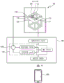
图1是简要地说明根据本发明一实施例的高尔夫球筛选装置结构的方框图。FIG. 1 is a block diagram briefly illustrating the structure of a golf ball screening device according to an embodiment of the present invention.
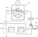
图2是根据本发明一实施例的高尔夫球筛选装置的立体图及侧视图。2 is a perspective view and a side view of a golf ball screening device according to an embodiment of the present invention.
图3是图2的变形例。FIG. 3 is a modified example of FIG. 2 .
图4是表示根据本发明另一实施例的高尔夫球筛选装置的图。FIG. 4 is a diagram showing a golf ball screening device according to another embodiment of the present invention.
图5是详细地表示图4的旋转支撑部的立体图。FIG. 5 is a perspective view illustrating in detail the rotation support portion of FIG. 4 .
图6及图7是分别表示图4的检测仪的变形例的图。6 and 7 are diagrams each showing a modified example of the detector shown in FIG. 4 .
图8是图4的变形例。FIG. 8 is a modified example of FIG. 4 .
图9及图10是分别表示图8的检测仪的变形例的图。9 and 10 are diagrams showing modification examples of the detector shown in FIG. 8 , respectively.
图11是表示电磁波信号对内外部对称的高尔夫球(a)、内部球核发生偏心的高尔夫球(b)、内部球核发生非对称不均衡的高尔夫球(c)、外壳发生损伤的高尔夫球(d)的透射及反射信号的图。Fig. 11 shows a golf ball (a) with internal and external symmetry of electromagnetic wave signals, a golf ball with eccentric inner core (b), asymmetrical and unbalanced inner core (c), and a golf ball with damaged shell (d) Plot of transmitted and reflected signals.
图12是用于说明高尔夫球的偏心率的高尔夫球的立体图。Fig. 12 is a perspective view of a golf ball for explaining the eccentricity of the golf ball.
图13及图14是表示利用根据本发明的高尔夫球筛选装置测量电磁波透射特性的结果的图表。13 and 14 are graphs showing the results of measuring electromagnetic wave transmission characteristics using the golf ball sorting device according to the present invention.
图15是表示针对在图14的(a)中筛选的球和在(b)中筛选的球进行115mph挥杆速度的木杆击球的结果的图表。FIG. 15 is a graph showing results of wood shots at a swing speed of 115 mph for the balls screened in (a) and (b) of FIG. 14 .
图16是表示针对在图14(a)中筛选的球和在(b)中筛选的球进行95mph挥杆速度的木杆击球的结果的图表。FIG. 16 is a graph showing the results of wood shots at a swing speed of 95 mph for the ball screened in FIG. 14( a ) and the ball screened in ( b ).
图17是表示针对在图14(a)中筛选的球和在(b)中筛选的球进行85mph挥杆速度的7号铁杆击球的结果的图表。FIG. 17 is a graph showing the results of a 7-iron shot at a swing speed of 85 mph for the ball screened in FIG. 14( a ) and the ball screened in ( b ).
图18是表示针对在图14(a)中筛选的球和在(b)中筛选的球进行75mph挥杆速度的劈起杆击球的结果的图表。FIG. 18 is a graph showing the results of pitching shots at a swing speed of 75 mph for the ball screened in FIG. 14( a ) and the ball screened in ( b ).
具体实施方式Detailed ways
在具体实施方式及附图中包括实施例的具体内容。The specific content of the embodiments is included in the detailed description and drawings.
若参照附图和详细后述的实施例,应能清楚地理解本发明的优点和特征、以及用于达到这些优点和特征的方法。但是,本发明并不局限于以下公开的实施例,可由各种不同的形式实现。本实施例只是用于完整地公开本发明,且为了向本发明所属技术领域的技术人员完整地告知发明的范畴而提供的,本发明只由权利要求的范畴来定义。在整个说明书中相同的附图标记表示相同的结构要素。Advantages and features of the present invention, and means for achieving the advantages and features will be clearly understood by referring to the accompanying drawings and embodiments described in detail later. However, the present invention is not limited to the embodiments disclosed below, and can be implemented in various forms. The present embodiment is provided only for completely disclosing the present invention and for fully informing the scope of the invention to those skilled in the art to which the present invention pertains, and the present invention is defined only by the scope of the claims. The same reference numerals denote the same structural elements throughout the specification.
下面,通过本发明的实施例,并参照用于说明高尔夫球筛选装置的附图,对本发明进行说明。Hereinafter, the present invention will be described through embodiments of the present invention with reference to the accompanying drawings for explaining the golf ball screening device.
图1是简要地说明根据本发明一实施例的高尔夫球筛选装置的结构的方框图。FIG. 1 is a block diagram briefly illustrating the structure of a golf ball screening device according to an embodiment of the present invention.
根据本发明一实施例的高尔夫球筛选装置可被构造为包括测量部100及分析部200。A golf ball screening device according to an embodiment of the present invention may be configured to include a measuring
测量部100可向被测对象高尔夫球发送信号,并接收从高尔夫球反射的信号或透射高尔夫球的信号。此时,可对高尔夫球的多个测量面收发信号。在此,测量面可以是与发送的信号的方向垂直的面。所述信号可为电磁波,作为一例可为RF(射频,RadioFrequency)电磁波信号,但并不局限于此。The
在测量部100中为了确认对被测对象高尔夫球的多个测量面反射或透射的电磁波的响应,接收在使被测对象高尔夫球旋转任一角度后反射或透射的第一电磁波,并且接收在使被测对象高尔夫球进一步旋转任一角度后反射或透射的第二电磁波。如此,通过使高尔夫球进行旋转并收发电磁波的方法,可对多个测量面反复进行测量。In the
此时,测量部100可被构造为包括:能够旋转地支撑被测对象高尔夫球的旋转支撑部;配置在高尔夫球的一侧且用于向高尔夫球发送电磁波的电磁波发送天线110;及配置在高尔夫球的另一侧且用于接收从电磁波发送天线发送的电磁波的电磁波接收天线120。即,可由高尔夫球另一侧的电磁波接收天线120来接收在高尔夫球一侧从电磁波发送天线110发送的电磁波信号,由此接收透射高尔夫球的电磁波信号。At this time, the
或者,测量部100可被构造为包括:能够旋转地支撑被测对象高尔夫球的旋转支撑部;及配置在高尔夫球的一侧且用于向高尔夫球发送电磁波并接收从高尔夫球反射的电磁波的电磁波收发天线1120。即,由配置在高尔夫球一侧的电磁波收发天线1120收发从高尔夫球反射的电磁波信号。Alternatively, the measuring
关于测量部100的详细结构,将在后面说明。The detailed configuration of the
分析部200对在使高尔夫球进行旋转的同时对多个测量面接收的信号进行分析来筛选高尔夫球。例如,当高尔夫球为内部球核的形状均匀的球状,且内部球核、内皮及外皮的结构左右对称的高尔夫球时,使高尔夫球进行旋转的同时接收的信号的均匀度应该较高。即,对多个测量面反射或透射的电磁波的大小及相位的相似度应该较高。可以推定对各测量面反射或透射的电磁波的大小及相位的差异越大,高尔夫球内部的不均匀性就越大。因此,在本发明中分析部200以通过旋转支撑部使高尔夫球进行旋转的同时接收的信号的均匀度为基础,筛选出内部介质均匀且接近于对称的高尔夫球。The
分析部200可由安装在包括计算装置及存储装置的计算机、或如智能电话的智能设备上的软件构成。The
在一实施例中,分析部200可使用深度学习技术来推定高尔夫球内部介质的偏心率或不均衡性。分析部200可使用深度学习技术来分类高尔夫球的偏心率或不均衡性的等级,或根据已设定的标准来判断不良。In one embodiment, the
图2是根据本发明一实施例的高尔夫球筛选装置的立体图及侧视图,图3是图2的变形例。FIG. 2 is a perspective view and a side view of a golf ball screening device according to an embodiment of the present invention, and FIG. 3 is a modified example of FIG. 2 .
参照图2,根据本实施例的高尔夫球筛选装置的测量部100可被构造为包括旋转支撑部及两个天线110、120。Referring to FIG. 2 , the measuring
旋转支撑部可被构造为包括高尔夫球支撑体130及旋转机构135。高尔夫球支撑体130将被测对象高尔夫球从地面竖直隔开来支撑。如图所示,高尔夫球支撑体130可形成为从地面朝向竖直上方延伸的杆状,在其上端可放置高尔夫球。旋转机构135用于使高尔夫球支撑体130以其竖直的轴为中心进行旋转。随着高尔夫球支撑体130通过旋转机构135旋转,可改变针对从电磁波发送天线110发送的信号的高尔夫球的测量面。此时,旋转机构135可使高尔夫球按任一角度进行旋转。所述旋转机构135可包括用于使高尔夫球支撑体130进行旋转的电机。The rotation support part may be configured to include the golf
此外,图2的测量部100可进一步包括天线支撑体115、125。天线支撑体115、125可包括:第一天线支撑体115及第二天线支撑体125,与高尔夫球支撑体130隔开,用于将电磁波发送天线110及电磁波接收天线120分别支撑,使之位于与由高尔夫球支撑体130支撑的高尔夫球水平的面上。In addition, the
进而,图2的测量部100可进一步包括在一面上支撑高尔夫球支撑体130及天线支撑体115、125的基座160。此时,在基座160的一面上的天线支撑体115、125和高尔夫球支撑体130之间设置有滑动孔(未图示),从而天线支撑体115、125可以能够滑动地结合在滑动孔中。因此,可调节天线支撑体115、125与高尔夫球支撑体130之间的隔开距离。Furthermore, the measuring
高尔夫球支撑体130和天线支撑体115、125分别以能够竖直延伸的方式设置,从而能够调节从基座160到支撑对象的竖直距离。The golf
在基座160的一面上可粘贴或涂覆有用于吸收电磁波的吸收体162。吸收体162可为铁氧体,但并不局限于此。吸收体162可吸收从电磁波发送天线110发送并被高尔夫球支撑体130或天线支撑体115、125散射的电磁波,从而防止电磁波接收天线120接收噪音。如图所示,吸收体162也可粘贴或涂覆在天线支撑体115、125上。An
电磁波发送天线110和电磁波接收天线120可与检测仪140连接。检测仪140用于产生电磁波并通过电磁波发送天线110和电磁波接收天线120收发电磁波,并输出及检测接收的电磁波的大小及相位。The electromagnetic
在本发明中,检测仪140可由多种形式形成。检测仪140可由发送电路1413和接收电路1414构成,或由网络分析仪1420构成,或由信号发生器1430和光谱分析仪1432构成,但并不局限于此。In the present invention, the
当检测仪140为网络分析仪1420时,在网络分析仪1420的电磁波发送侧和电磁波接收侧上连接电磁波发送天线110和电磁波接收天线120。当检测仪140由信号发生器1430和光谱分析仪1432构成时,在信号发生器1430上连接电磁波发送天线110,在光谱分析仪1432上连接电磁波接收天线120。When the
检测仪140与分析部200连接,从而能够传输检测的电磁波的大小及相位。The
图3表示图2所示测量部100的变形例。在以下说明中以与前述实施例的不同点为中心进行说明。FIG. 3 shows a modified example of the measuring
参照图3,在本实施例中配置有由电磁波发送天线110和电磁波接收天线120一体形成的电磁波收发天线1120。Referring to FIG. 3 , in this embodiment, an electromagnetic wave transmitting and receiving
由高尔夫球支撑体130及旋转机构135构成的旋转支撑部的结构与前述的结构相同。The structure of the rotation support part comprised by the golf
天线支撑体1125用于支撑电磁波收发天线1120。天线支撑体1125与高尔夫球支撑体130隔开,用于将电磁波收发天线1120支撑在与由高尔夫球支撑体130支撑的被测对象高尔夫球水平的面上。The
与图2的实施例同样地,天线支撑体1125在与高尔夫球支撑体130之间能够滑动地配置,从而能够调节与高尔夫球支撑体130的隔开距离。2 , the
与图2比较,电磁波收发天线1120与检测仪140连接,可以仅接收从被测对象高尔夫球的多个测量面反射的电磁波。Compared with FIG. 2 , the electromagnetic wave transmitting and receiving
检测仪140与电磁波收发天线1120连接,用于收发电磁波,并检测接收的电磁波的大小及相位,并将检测结果传输给分析部200。The
图4是表示根据本发明另一实施例的高尔夫球筛选装置的图,图5是详细地表示图4的旋转支撑部的立体图,图6及图7是分别表示图4的检测仪的变形例的图,图8是图4的变形例,图9及图10分别是表示图8的检测仪的变形例的图。4 is a diagram showing a golf ball sorting device according to another embodiment of the present invention, FIG. 5 is a perspective view showing in detail the rotating support part of FIG. 8 is a modified example of FIG. 4, and FIGS. 9 and 10 are diagrams showing modified examples of the detector in FIG. 8, respectively.
在本实施例中,测量部100可由旋转支撑部、电磁波发送天线110及电磁波接收天线120构成。In this embodiment, the measuring
图5所示的旋转支撑部用于支撑高尔夫球,并使高尔夫球旋转来改变其姿势。旋转支撑部可被构造为包括第一旋转支撑板170、用于使第一旋转支撑板170旋转的第一电机171、第二旋转支撑板172、用于使第二旋转支撑板172旋转的第二电机173。此外,旋转支撑部可进一步包括旋转杆174。The rotation support part shown in FIG. 5 supports a golf ball and rotates the golf ball to change its posture. The rotation support part may be configured to include a first
如图所示,第一旋转支撑板170和第一电机171可被支撑并固定在六面体结构的框架180中。第一旋转支撑板170为圆板或圆柱状并被配置为其轴向与地面平行,如图所示,第一旋转支撑板170可利用侧面支撑作为高尔夫球的横侧面的第一位置。在第一旋转支撑板170的中心轴上连接有第一电机171的电机轴,可通过第一电机171的驱动,使第一旋转支撑板170进行旋转。因此,可通过第一旋转支撑板170的旋转,使在第一位置上受到支撑的高尔夫球进行旋转来改变高尔夫球的姿势。As shown, the first
第二旋转支撑板172及第二电机173与第一旋转支撑板170及第一电机171为相同的形状,其可支撑作为高尔夫球的横侧面的第二位置。此时,优选第一旋转支撑板170和第二旋转支撑板172配置为在彼此正交的方向上分别支撑高尔夫球的左右中心,从而使支撑高尔夫球的第一位置和第二位置成为以高尔夫球中心为基准正交的两个位置。The second
可通过第一电机171使第一旋转支撑板170旋转或通过第二电机173使第二旋转支撑板172旋转来使高尔夫球在正交的两个方向上进行旋转。因此,可将高尔夫球的姿势改变为多种形式,从而能够使高尔夫球的全部面积位于朝向固定配置的电磁波发送天线110或电磁波接收天线120的位置。The golf ball can be rotated in two orthogonal directions by rotating the first
旋转杆174为两侧自由旋转的杆,杆的中央外侧面支撑高尔夫球的第三位置。此时,如图所示,从上侧向下观察时,以高尔夫球中央为中心,第三位置优选可位于第一位置和第二位置的相反侧的中央,从侧面观察时,第三位置优选支撑高尔夫球的下侧部。为了能够支撑旋转杆174,一对固定杆175从框架180向内侧延伸,旋转杆174的两端可分别能够自由旋转地固定在固定杆175的两端。The
因此,通过第一旋转支撑板170、第二旋转支撑板172及旋转杆174支撑高尔夫球的下侧部的三个位置,当第一旋转支撑板170或第二旋转支撑板172在电机的驱动下进行旋转时,旋转杆174自由旋转,从而能够将高尔夫球稳定地支撑的同时使之旋转。Therefore, through the three positions of the lower side of the golf ball supported by the first
电磁波发送天线110可配置在高尔夫球的一侧,用于向高尔夫球发送信号。在框架180的上端面上可形成有固定槽182,以便能够易于固定电磁波发送天线110。The electromagnetic
电磁波接收天线120可配置在高尔夫球的另一侧,用于接收从电磁波发送天线110向高尔夫球发送且透射高尔夫球的信号。The electromagnetic
如图4所示,在作为规定的电路板的控制板190上可形成有MCU(Micro ControllerUnit,微型控制装置)1411、用于控制第一电机171或第二电机173的驱动的电机控制部1412及检测仪140。As shown in FIG. 4 , an MCU (Micro Controller Unit, micro control device) 1411, a
检测仪140可包括:用于产生待从电磁波发送天线110发送的信号并将其传输给电磁波发送天线110的发送电路1413;和用于接收从电磁波接收天线120接收的信号并处理与信号的大小及相位相关的信息的接收电路1414。通信部1415可将由接收电路1414处理后的信号传输到作为外部设备的由如智能手机和智能平板的终端或PC等构成的分析部200。所述通信部1415可通过有线或无线方式发送数据,在图4中示出利用BLE信号向如智能手机的终端传送在接收电路1414中处理后的信号的结构。在接收所述信号的分析部200中可以分析所接收的信号并判断高尔夫球的均匀度特性后在显示屏上显示筛选结果。The
图6表示图4的检测仪140的变形例,在本实施例中,网络分析仪1420执行前述收发电路的功能,其用于产生待从电磁波发送天线110发送的信号并传输给电磁波发送天线110,接收从电磁波接收天线120接收的信号并进行处理。此时,与在网络分析仪1420中处理后的信号的大小和相位相关的信息可实时传输到分析部200,在本实施例中示出分析部200由PC构成的模样。用于驱动第一电机171或第二电机173的电机控制部1412的操作可通过PC的控制命令来控制。Fig. 6 shows the modified example of the
图7表示图4的检测仪的另一变形例,在本实施例中,由用于产生待从电磁波发送天线110发送的信号并传输给电磁波发送天线110的信号发生器1430及用于接收从电磁波接收天线120接收的信号并进行处理的光谱分析仪1432执行收发电路的功能。此时,与在光谱分析仪1432中处理后的信号的大小和相位相关的信息可实时传输到分析部200,在本实施例中也示出分析部200由PC构成的模样。Fig. 7 represents another modified example of the detector of Fig. 4, in this embodiment, by the
在本实施例中,用于驱动第一电机171或第二电机173的电机驱动部1412的操作也可通过PC的控制命令来控制。In this embodiment, the operation of the
图8表示图4所示测量部100的变形例。在以下说明中以与前述实施例的不同点为中心进行说明。FIG. 8 shows a modified example of the measuring
参照图8,在本实施例中配置有由电磁波发送天线110和电磁波接收天线120一体形成的电磁波收发天线1120。Referring to FIG. 8 , in this embodiment, an electromagnetic wave transmitting and receiving
根据本实施例的高尔夫球筛选装置可被构造为包括旋转支撑部、电磁波收发天线1120及分析部200。The golf ball screening device according to the present embodiment may be configured to include a rotating support part, an electromagnetic wave transmitting and receiving
在前面参照图4进行说明的实施例中使用配置在高尔夫球一侧的电磁波发送天线110和配置在高尔夫球另一侧的电磁波接收天线120,具体由电磁波接收天线120接收从电磁波发送天线110发送并透射高尔夫球的信号并以接收的信号为基础筛选高尔夫球。而在本实施例中,可由配置在高尔夫球的一侧且用于向高尔夫球发送信号并接收从高尔夫球反射的信号的电磁波收发天线1120来形成。In the embodiment described above with reference to FIG. 4 , the electromagnetic
如图8所示,在本实施例中也与图4的实施例同样地,在控制板190上可形成有MCU1411、用于控制电机的驱动的电机控制部1412、用于产生待从电磁波收发天线1120发送的信号并传输的发送电路1413、用于处理从电磁波收发天线1120接收的信号的接收电路1414及用于将由接收电路1414处理后的信号传送到外部的由终端或PC构成的分析部200的通信部1415。As shown in Figure 8, in this embodiment, like the embodiment of Figure 4, an
此外,如图9所示,与图6的实施例同样地,可由网络分析仪1420执行收发电路的功能,其用于产生待从电磁波收发天线1120发送的信号并传输给电磁波收发天线1120,接收从电磁波收发天线1120接收的信号并进行处理。此时,与由网络分析仪1420处理后的信号的大小和相位相关的信息可实时传输到分析部200,并将筛选的结果显示在显示器上。In addition, as shown in Figure 9, similar to the embodiment of Figure 6, the function of the transceiver circuit can be performed by the
此时,用于驱动第一电机171或第二电机173的电机控制部1412的操作可通过PC的控制命令来控制。At this time, the operation of the
此外,如图10所示,与图7的实施例同样地,可由用于产生待从电磁波收发天线1120发送的信号并传输给电磁波收发天线1120的信号发生器1430及用于接收从电磁波收发天线1120接收的信号并进行处理的光谱分析仪1432执行收发电路的功能。此时,与由光谱分析仪1432处理后的信号的大小和相位相关的信息可实时传输到分析部200,并将分析部200中筛选的结果显示在显示器上。In addition, as shown in FIG. 10 , similar to the embodiment of FIG. 7 , a
在本实施例中,用于驱动第一电机171或第二电机173的电机控制部1412的操作也可通过PC的控制命令来控制。In this embodiment, the operation of the
另外,在图8至图10的实施例中,检测仪140可进一步配置有用于在信号的传输过程中区分收发信号的环形器(circulator)1440。In addition, in the embodiments shown in FIG. 8 to FIG. 10 , the
在以下说明中,对根据本发明的高尔夫球的筛选原理及关于筛选效果的实验结果进行说明。In the following description, the screening principle of the golf ball according to the present invention and the experimental results on the screening effect will be described.
图11是表示电磁波信号对内外部对称的高尔夫球(a)、内部球核偏心的高尔夫球(b)、内部球核非对称不均匀的高尔夫球(c)、外部壳体发生损伤的高尔夫球(d)的透射及反射的图,图12是用于说明高尔夫球的偏心率的高尔夫球的立体图。Fig. 11 shows that the electromagnetic wave signal damages a golf ball with internal and external symmetry (a), a golf ball with an eccentric inner core (b), a golf ball with an asymmetric and uneven inner core (c), and a golf ball with an outer shell (d) In the diagram of transmission and reflection, FIG. 12 is a perspective view of a golf ball for explaining the eccentricity of the golf ball.
高尔夫球的球核、内皮及外皮可由彼此不同的材质构成。例如,高尔夫球可由橡胶材质的球核;塑料材质的内皮层;热固性聚氨酯、热塑性聚氨酯、离聚物塑料(IonomerPlastic)材质的外皮层构成。此外,为了增大高尔夫球的飞行距离,开发出多种材料并应用于高尔夫球,各制造商还将复合材料混合应用于高尔夫球上。The core, the inner cover, and the outer cover of the golf ball may be made of different materials. For example, the golf ball can be composed of a core made of rubber; an inner skin layer made of plastic; and an outer skin layer made of thermosetting polyurethane, thermoplastic polyurethane, or ionomer plastic. In addition, in order to increase the flight distance of golf balls, various materials have been developed and applied to golf balls, and various manufacturers have also mixed composite materials and applied them to golf balls.
当从电磁波发送天线110或电磁波收发天线1120发送的电磁波入射到高尔夫球时,在构成高尔夫球的不同材质的边界面上会产生入射波的散射及透射。此时,反射波可再次传输到电磁波收发天线1120,透射的波可被相反侧的电磁波接收天线120接收。电磁波的反射及透射特性对介质的介电常数非常敏感,因此根据高尔夫球内部的介质均匀度,反射或透射的电磁波的大小及相位特性有可能不同。When the electromagnetic wave transmitted from the electromagnetic
如图11的(a)所示,当所制造的高尔夫球的内部在结构/物理性质上对称及均匀时,在使高尔夫球旋转的同时测量的反射或透射特性将是均匀的。此时,高尔夫球的球核及外皮具有彼此不同的物理性质,且高尔夫球的直径为约42mm。优选选择在这种高尔夫球的球核及外皮的物理性质上表现出良好反应性的频率来进行测量。As shown in (a) of FIG. 11 , when the inside of the manufactured golf ball is symmetrical and uniform in structure/physical properties, the reflection or transmission characteristics measured while rotating the golf ball will be uniform. At this time, the core and the cover of the golf ball have physical properties different from each other, and the diameter of the golf ball is about 42 mm. It is preferable to select a frequency that exhibits good reactivity in the physical properties of the core and cover of such a golf ball for measurement.
相反,当如图11的(b)所示那样内部的球核层向特定方向偏心,或如图11的(c)所述那样内部的球核层的介质不对称时,在每个测量面上反射或透射的电磁波的特性会彼此不同。Conversely, when the inner core layer is eccentric in a specific direction as shown in (b) of FIG. 11, or the medium of the inner core layer is asymmetrical as shown in FIG. 11 (c), each measurement surface The characteristics of the reflected or transmitted electromagnetic waves will differ from each other.
此外,在如图11的(d)所示那样在外壳上发生非对称损伤时,在每个测量面上测量的反射或透射特性也有可能不同。外部瑕疵与高尔夫球的大小相比相对很小,因此优选以与检测高尔夫球内部的均匀性及偏心时相比更高的频率来进行测量。In addition, when asymmetrical damage occurs on the housing as shown in (d) of FIG. 11 , there is a possibility that the measured reflection or transmission characteristics may be different for each measurement surface. External blemishes are relatively small compared to the size of the golf ball, so it is preferable to measure them at a higher frequency than when detecting the uniformity and decentration inside the golf ball.
因此,在本发明中可以在通过旋转支撑部使高尔夫球旋转的同时测量的电磁波的特性(反射或透射的信号的大小及相位的均匀度)为基准,将高尔夫球的内部均匀度定量化来评价。Therefore, in the present invention, the internal uniformity of the golf ball can be quantified based on the characteristics of electromagnetic waves (the magnitude and phase uniformity of the reflected or transmitted signal) measured while the golf ball is rotated by the rotating support. evaluate.
参照图12,如数学式1所示,偏心率可由高尔夫球的中心P1到球核中心P2的距离r与高尔夫球的半径之比来表示。Referring to FIG. 12 , as shown in
[数学式1][mathematical formula 1]
偏心率(ε)=r(高尔夫球的中心到球核中心的距离)/R(高尔夫球的半径)Eccentricity (ε) = r (the distance from the center of the golf ball to the center of the core) / R (the radius of the golf ball)
通过数学式1可知,当球核准确地位于高尔夫球的中心,从而高尔夫球的中心和球核的中心重合时,从高尔夫球的中心到球核中心的距离r为0,因此偏心率也为0。此外,从高尔夫球的中心到球核中心的距离越远,r就越大,因此偏心率ε也会变大。It can be known from
图13及图14是表示利用根据本发明的高尔夫球筛选装置测量电磁波透射特性的结果的图表,图15是表示对在图14的(a)中筛选的球和在(b)中筛选的球进行115mph挥杆速度的木杆击球的结果的图表,图16是表示对在图14的(a)中筛选的球和在(b)中筛选的球进行95mph挥杆速度的木杆击球的结果的图表,图17是表示对在图14的(a)中筛选的球和在(b)中筛选的球进行85mph挥杆速度的7号铁杆击球的结果的图表,图18是表示对在图14的(a)中筛选的球和在(b)中筛选的球进行75mph挥杆速度的劈起杆击球的结果的图表。13 and FIG. 14 are graphs showing the results of measuring electromagnetic wave transmission characteristics using a golf ball sorting device according to the present invention, and FIG. 15 shows a comparison between the balls sorted in (a) and the balls sorted in (b) of FIG. 14 . 16 is a graph showing the results of a wood shot with a swing speed of 115 mph, and FIG. 16 shows a wood shot with a swing speed of 95 mph for the ball screened in (a) and the ball screened in (b) of FIG. 14 Figure 17 is a graph showing the results of a 7-iron shot at a swing speed of 85 mph for the ball screened in (a) of Figure 14 and the ball screened in (b), and Figure 18 is a graph showing Graph of the results of pitching shots with a swing speed of 75 mph for the balls screened in (a) and (b) of FIG. 14 .
图13的(a)表示的是在不同的不良高尔夫球偏心率下所接收的电磁波相对于频率的大小,图13的(b)表示的是在不同的不良高尔夫球偏心率下所接收的电磁波相对于频率的相位。参照图13可知,当偏心率不同时,电磁波的透射大小和位置均不同。可知当偏心率从0增加到0.2时,在低于F3频率的频率下透射大小逐渐增加,在高于F3频率的频率下随着偏心率的增加,透射大小逐渐减小。Figure 13(a) shows the magnitude of the received electromagnetic waves relative to the frequency under different bad golf ball eccentricities, and Figure 13(b) shows the received electromagnetic waves under different bad golf ball eccentricities Phase with respect to frequency. Referring to FIG. 13, it can be seen that when the eccentricity is different, the transmission size and position of the electromagnetic wave are different. It can be seen that when the eccentricity increases from 0 to 0.2, the transmission size gradually increases at frequencies lower than the F3 frequency, and the transmission size gradually decreases with the increase of the eccentricity at frequencies higher than the F3 frequency.
尤其,在相位特性上,根据偏心程度在特定频率F2~F5之间表现出大小及相位敏感地变化的情况。因此,可基于电磁波的透射及反射特性推定包括高尔夫球内部的偏心在内的对称性的不均衡程度。In particular, in terms of the phase characteristics, the magnitude and phase sensitively change between the specific frequencies F2 to F5 according to the degree of eccentricity. Therefore, the degree of imbalance in symmetry including the eccentricity inside the golf ball can be estimated based on the transmission and reflection characteristics of electromagnetic waves.
尤其,可将偏心率、透射及反射特性的数据集应用到深度学习技术来定量化偏心率及均衡性,并由此实现不良高尔夫球的自动筛选。In particular, the data sets of eccentricity, transmission and reflection characteristics can be applied to deep learning technology to quantify eccentricity and balance, and thus realize automatic screening of bad golf balls.
图14是利用根据本发明高尔夫球筛选装置测量市售的特定品牌高尔夫球的电磁波透射特性的结果。在使同一个包装箱内的高尔夫球进行旋转的同时测量透射系数,并筛选透射系数的最大值和最小值之间的差值(SOD:Sum of Deviation,偏差和)最小的高尔夫球(球-A)(图14的(a))和差值最大的高尔夫球(球-B)(图14的(b))。FIG. 14 is the result of measuring the electromagnetic wave transmission characteristics of commercially available golf balls of a specific brand using the golf ball screening device according to the present invention. Measure the transmittance while rotating the golf balls in the same box, and select the golf ball (ball- A) ((a) of FIG. 14 ) and the golf ball (Ball-B) with the largest difference ((b) of FIG. 14 ).
通过图14的测量结果可知,球-A和球-B的最大透射系数值基本相同,但是对最小透射系数来讲,球-B比球-A在所有测量频率中低1dB左右。From the measurement results in Figure 14, it can be seen that the maximum transmission coefficient values of ball-A and ball-B are basically the same, but for the minimum transmission coefficient, ball-B is about 1dB lower than ball-A in all measurement frequencies.
为了验证在用高尔夫球杆击打实际球时,被筛选的球-A和球-B在飞行特性(飞行距离及左右偏差)上的区别有多大,利用KIGOS(Korea Institute of Golf and Sports,韩国高尔夫体育研究院)的挥杆机器人进行测试。与人的挥杆不同,机器人可以相同的速度和机制反复进行高尔夫挥杆,因此每次挥杆时都能击打球杆面的相同位置。利用Foresight的GC Quad launch monitor,GC Quad挥杆监视器)分析高尔夫球的飞行轨迹。GC Quadlaunch monitor排除风或湿度等影响高尔夫球飞行的外部因素,因此可提供仅根据高尔夫球特性的严格的飞行轨迹结果。In order to verify the difference between the screened ball-A and ball-B in flight characteristics (flight distance and left-right deviation) when hitting an actual ball with a golf club, KIGOS (Korea Institute of Golf and Sports, Korea Institute of Golf and Sports, Korea Institute of Golf and Sports, Korea Golf Sports Research Institute) swing robot for testing. Unlike a human swing, a robot can repeat a golf swing with the same speed and mechanics, so it hits the same spot on the clubface every time. Use Foresight's GC Quad launch monitor, GC Quad swing monitor) to analyze the flight trajectory of the golf ball. The GC Quadlaunch monitor excludes external factors such as wind or humidity that affect the flight of the golf ball, thus providing stringent flight trajectory results based only on the characteristics of the golf ball.
木杆击球使用95mph和115mph(中速及快速)这两种挥杆速度进行测试。将安装有65克普通硬度杆身和75克超硬度杆身的泰特利斯TSi2木杆分别用于95英里及115英里挥杆。此外,使用Fourteen TC-544锻造铁杆对7号铁杆(85mph)和劈起杆(75mph)进行同样的测试。Woods were tested using two swing speeds of 95mph and 115mph (medium and fast). Titlis TSi2 woods with 65-gram regular-stiff shafts and 75-gram extra-stiff shafts were used for the 95-mile and 115-mile swings, respectively. Additionally, the same test was performed on a 7 iron (85mph) and a pitching wedge (75mph) using Fourteen TC-544 forged irons.
此外,在每个高尔夫球的表面上标注数字“1”到“14”,使得测试球杆能够击打球的14个不同位置,按每个高尔夫球测量14次击球的距离及左右偏移偏差。In addition, the numbers "1" to "14" are marked on the surface of each golf ball, so that the test club can hit 14 different positions of the ball, and the distance and left-right deviation of 14 hits are measured for each golf ball .
115mph及95mph挥杆速度的木杆击球测试结果清楚地表示球-A和球-B的区别(图15及图16)。SOD较低的球飞行距离偏差更小,尤其需要注意的是球-A的左右偏移偏差远远优于球-B。具有较高SOD的球-B的偏移偏差比球-A大2.4倍以上。对7号铁杆和劈起杆击球的测试结果也可在图17和图18中确认,且可确认到与木杆击球结果同样地,SOD较低的球-A比球-B表现出更优异的一致性。The wood hit test results at 115mph and 95mph swing speeds clearly show the difference between Ball-A and Ball-B (Figures 15 and 16). Balls with a lower SOD have smaller flying distance deviations, and it is especially important to note that the left and right deviations of ball-A are much better than ball-B. Ball-B with a higher SOD has more than 2.4 times greater offset deviation than Ball-A. The test results of the 7-iron and pitching shots can also be confirmed in Figures 17 and 18, and it can be confirmed that, similar to the results of shots with woods, Ball-A with a lower SOD exhibited Better consistency.
本发明的权利范围并不限于上述实施例,在所附的权利要求书的范围内可由多种形式的实施例实现。在不脱离权利要求书中所要求保护的本发明精神的范围内,本发明所属技术领域的技术人员均能变形的各种范围也属于本发明的权利要求书中记载的范围内。The scope of rights of the present invention is not limited to the above-described embodiments, and various forms of embodiments can be realized within the scope of the appended claims. Various ranges that can be modified by those skilled in the art to which the present invention pertains also fall within the scope described in the claims of the present invention without departing from the spirit of the present invention claimed in the claims.
Claims (16)
Applications Claiming Priority (5)
| Application Number | Priority Date | Filing Date | Title |
|---|---|---|---|
| KR1020210082339A KR102569745B1 (en) | 2021-06-24 | 2021-06-24 | Golf ball balance analysis apparatus |
| KR10-2021-0082339 | 2021-06-24 | ||
| KR1020210128704A KR102706945B1 (en) | 2021-09-29 | 2021-09-29 | Apparatus for selecting high-quality golf ball |
| KR10-2021-0128704 | 2021-09-29 | ||
| PCT/KR2022/008762 WO2022270864A1 (en) | 2021-06-24 | 2022-06-21 | Golf ball sorting device |
Publications (2)
| Publication Number | Publication Date |
|---|---|
| CN116324399A true CN116324399A (en) | 2023-06-23 |
| CN116324399B CN116324399B (en) | 2026-04-10 |
Family
ID=84545573
Family Applications (1)
| Application Number | Title | Priority Date | Filing Date |
|---|---|---|---|
| CN202280006154.4A Active CN116324399B (en) | 2021-06-24 | 2022-06-21 | Golf ball screening device |
Country Status (5)
| Country | Link |
|---|---|
| US (1) | US12296231B2 (en) |
| EP (1) | EP4335521B1 (en) |
| JP (1) | JP7505828B2 (en) |
| CN (1) | CN116324399B (en) |
| WO (1) | WO2022270864A1 (en) |
Families Citing this family (2)
| Publication number | Priority date | Publication date | Assignee | Title |
|---|---|---|---|---|
| WO2022270864A1 (en) * | 2021-06-24 | 2022-12-29 | (주)엠텔리 | Golf ball sorting device |
| KR102660995B1 (en) * | 2023-09-25 | 2024-04-25 | (주)엠텔리 | Golf ball inspection device |
Citations (7)
| Publication number | Priority date | Publication date | Assignee | Title |
|---|---|---|---|---|
| JPH04364402A (en) * | 1991-06-11 | 1992-12-16 | Toshiba Corp | Eccentricity inspection method |
| JPH08229810A (en) * | 1995-02-24 | 1996-09-10 | Hinode Eng Kk | Attitude correcting device for golf ball having burr, and deburring machine using it |
| JPH08271446A (en) * | 1995-03-30 | 1996-10-18 | Ntn Corp | Method and apparatus for inspecting appearance of spherical body |
| US20040042586A1 (en) * | 2002-08-28 | 2004-03-04 | Furze Paul A. | Golf ball inspection using metal markers |
| JP2015087378A (en) * | 2013-09-25 | 2015-05-07 | 株式会社東芝 | Inspection device and inspection system |
| KR20170136906A (en) * | 2016-06-02 | 2017-12-12 | 고성우 | Method And Device for Inspecting the Crack of Sphere |
| JP2018072252A (en) * | 2016-11-01 | 2018-05-10 | 倉敷紡績株式会社 | Inspection device and inspection method for surface of spherical object |
Family Cites Families (22)
| Publication number | Priority date | Publication date | Assignee | Title |
|---|---|---|---|---|
| JPS5563758A (en) * | 1978-11-08 | 1980-05-14 | Sumitomo Rubber Ind Ltd | Method of discriminating type of golf ball |
| DE3926684A1 (en) * | 1989-08-12 | 1991-02-14 | Guenter Prof Dr Hermann | Golf ball locating device - analyses electromagnetic locating beam reflected from or transmitted from specially prepared golf ball |
| JPH06126015A (en) * | 1992-01-04 | 1994-05-10 | Hiroshi Imanishi | Golf ball position searching system |
| JPH06237090A (en) | 1993-02-08 | 1994-08-23 | Hitachi Eng Co Ltd | Anechoic chamber |
| FR2708472A1 (en) * | 1993-05-03 | 1995-02-10 | Veillerot Christiane | Additional electronic and electromagnetic device added to golf balls in order to locate and identify them |
| KR0176661B1 (en) * | 1995-12-28 | 1999-05-15 | 김광호 | Inspecting method & apparatus of soldering section |
| JPH1137881A (en) * | 1997-07-17 | 1999-02-12 | Sumitomo Rubber Ind Ltd | Apparatus and method for detecting eccentricity |
| SE518997C2 (en) * | 2001-04-02 | 2002-12-17 | Impressonic Ab | Method and apparatus for detecting damage in materials or articles |
| US7116413B2 (en) | 2002-09-13 | 2006-10-03 | Kla-Tencor Corporation | Inspection system for integrated applications |
| JP2004230325A (en) * | 2003-01-31 | 2004-08-19 | Kazuya Shiraiwa | Golf ball sorting method and apparatus |
| JP2005205091A (en) * | 2004-01-26 | 2005-08-04 | Bridgestone Sports Co Ltd | Golf ball |
| JP5917218B2 (en) * | 2012-03-19 | 2016-05-11 | 八光オートメーション株式会社 | Internal defect inspection apparatus and internal defect inspection method |
| KR101358177B1 (en) | 2012-04-03 | 2014-02-07 | 양서일 | Golf ball test device |
| WO2013172015A1 (en) * | 2012-05-16 | 2013-11-21 | 横浜ゴム株式会社 | Ball for ball game |
| KR102012601B1 (en) | 2018-11-22 | 2019-08-20 | 주식회사 담스테크 | Analyzer for analyzing biological effects of electromagnetic waves |
| US11752396B1 (en) * | 2020-02-19 | 2023-09-12 | Topgolf Callaway Brands Corp. | Method and system utilizing imaging analysis for golf balls |
| US11058924B1 (en) | 2020-02-19 | 2021-07-13 | Callaway Golf Company | Method and system utilizing imaging analysis for golf balls |
| US20220184463A1 (en) * | 2020-12-10 | 2022-06-16 | Michael Ganson | Sports ball system for monitoring ball characteristics and method therefor |
| WO2022270864A1 (en) * | 2021-06-24 | 2022-12-29 | (주)엠텔리 | Golf ball sorting device |
| US11543241B1 (en) * | 2021-07-07 | 2023-01-03 | Acushnet Company | Multi-energy x-ray system and method for golf ball inspection |
| US11668560B1 (en) * | 2021-07-19 | 2023-06-06 | Acushnet Company | X-ray system and method for golf ball inspection |
| JP2025063758A (en) * | 2023-10-04 | 2025-04-16 | 株式会社デンソー | Spark plugs for internal combustion engines |
-
2022
- 2022-06-21 WO PCT/KR2022/008762 patent/WO2022270864A1/en not_active Ceased
- 2022-06-21 EP EP22828711.6A patent/EP4335521B1/en active Active
- 2022-06-21 JP JP2023506290A patent/JP7505828B2/en active Active
- 2022-06-21 CN CN202280006154.4A patent/CN116324399B/en active Active
- 2022-06-21 US US17/907,609 patent/US12296231B2/en active Active
Patent Citations (7)
| Publication number | Priority date | Publication date | Assignee | Title |
|---|---|---|---|---|
| JPH04364402A (en) * | 1991-06-11 | 1992-12-16 | Toshiba Corp | Eccentricity inspection method |
| JPH08229810A (en) * | 1995-02-24 | 1996-09-10 | Hinode Eng Kk | Attitude correcting device for golf ball having burr, and deburring machine using it |
| JPH08271446A (en) * | 1995-03-30 | 1996-10-18 | Ntn Corp | Method and apparatus for inspecting appearance of spherical body |
| US20040042586A1 (en) * | 2002-08-28 | 2004-03-04 | Furze Paul A. | Golf ball inspection using metal markers |
| JP2015087378A (en) * | 2013-09-25 | 2015-05-07 | 株式会社東芝 | Inspection device and inspection system |
| KR20170136906A (en) * | 2016-06-02 | 2017-12-12 | 고성우 | Method And Device for Inspecting the Crack of Sphere |
| JP2018072252A (en) * | 2016-11-01 | 2018-05-10 | 倉敷紡績株式会社 | Inspection device and inspection method for surface of spherical object |
Also Published As
| Publication number | Publication date |
|---|---|
| CN116324399B (en) | 2026-04-10 |
| JP2023536867A (en) | 2023-08-30 |
| WO2022270864A1 (en) | 2022-12-29 |
| EP4335521A1 (en) | 2024-03-13 |
| US12296231B2 (en) | 2025-05-13 |
| EP4335521B1 (en) | 2025-12-10 |
| US20240207693A1 (en) | 2024-06-27 |
| EP4335521A4 (en) | 2024-10-23 |
| JP7505828B2 (en) | 2024-06-25 |
Similar Documents
| Publication | Publication Date | Title |
|---|---|---|
| KR102636526B1 (en) | System and method for determining spin measurements using ball marking | |
| CN116324399A (en) | golf ball screening device | |
| JP4865735B2 (en) | Determination of sports ball rotation parameters | |
| JP6422485B2 (en) | Dynamic sampling in sports equipment | |
| US8251841B2 (en) | Method and apparatus for analyzing a golf swing | |
| EP2973503B1 (en) | Impact and sound analysis for golf equipment | |
| US20070105637A1 (en) | Golf ball performance evaluation system | |
| EP2973504B1 (en) | Impact and sound analysis for golf equipment | |
| US9245457B2 (en) | Impact and sound analysis for golf equipment | |
| JP2011200641A (en) | Golf ball with piezoelectric material | |
| KR102569745B1 (en) | Golf ball balance analysis apparatus | |
| KR101772521B1 (en) | Ball for ball games | |
| US11040244B2 (en) | Impact and sound analysis for golf equipment | |
| KR102706945B1 (en) | Apparatus for selecting high-quality golf ball | |
| WO2013014932A1 (en) | Sports ball | |
| Shannon et al. | On the acoustic signature of golf ball impact | |
| US11731007B2 (en) | Wireless billiard ball device |
Legal Events
| Date | Code | Title | Description |
|---|---|---|---|
| PB01 | Publication | ||
| PB01 | Publication | ||
| SE01 | Entry into force of request for substantive examination | ||
| SE01 | Entry into force of request for substantive examination | ||
| GR01 | Patent grant | ||
| GR01 | Patent grant |