CN116324329A - System for detecting changes in physical properties of elastomeric materials - Google Patents
System for detecting changes in physical properties of elastomeric materials Download PDFInfo
- Publication number
- CN116324329A CN116324329A CN202180069064.5A CN202180069064A CN116324329A CN 116324329 A CN116324329 A CN 116324329A CN 202180069064 A CN202180069064 A CN 202180069064A CN 116324329 A CN116324329 A CN 116324329A
- Authority
- CN
- China
- Prior art keywords
- srr
- tire
- carbon
- frequency
- vehicle
- Prior art date
- Legal status (The legal status is an assumption and is not a legal conclusion. Google has not performed a legal analysis and makes no representation as to the accuracy of the status listed.)
- Pending
Links
Images


Classifications
-
- B—PERFORMING OPERATIONS; TRANSPORTING
- B60—VEHICLES IN GENERAL
- B60C—VEHICLE TYRES; TYRE INFLATION; TYRE CHANGING; CONNECTING VALVES TO INFLATABLE ELASTIC BODIES IN GENERAL; DEVICES OR ARRANGEMENTS RELATED TO TYRES
- B60C11/00—Tyre tread bands; Tread patterns; Anti-skid inserts
- B60C11/24—Wear-indicating arrangements
- B60C11/243—Tread wear sensors, e.g. electronic sensors
-
- B—PERFORMING OPERATIONS; TRANSPORTING
- B60—VEHICLES IN GENERAL
- B60C—VEHICLE TYRES; TYRE INFLATION; TYRE CHANGING; CONNECTING VALVES TO INFLATABLE ELASTIC BODIES IN GENERAL; DEVICES OR ARRANGEMENTS RELATED TO TYRES
- B60C19/00—Tyre parts or constructions not otherwise provided for
-
- B—PERFORMING OPERATIONS; TRANSPORTING
- B60—VEHICLES IN GENERAL
- B60C—VEHICLE TYRES; TYRE INFLATION; TYRE CHANGING; CONNECTING VALVES TO INFLATABLE ELASTIC BODIES IN GENERAL; DEVICES OR ARRANGEMENTS RELATED TO TYRES
- B60C23/00—Devices for measuring, signalling, controlling, or distributing tyre pressure or temperature, specially adapted for mounting on vehicles; Arrangement of tyre inflating devices on vehicles, e.g. of pumps or of tanks; Tyre cooling arrangements
- B60C23/02—Signalling devices actuated by tyre pressure
- B60C23/04—Signalling devices actuated by tyre pressure mounted on the wheel or tyre
- B60C23/0408—Signalling devices actuated by tyre pressure mounted on the wheel or tyre transmitting the signals by non-mechanical means from the wheel or tyre to a vehicle body mounted receiver
- B60C23/0422—Signalling devices actuated by tyre pressure mounted on the wheel or tyre transmitting the signals by non-mechanical means from the wheel or tyre to a vehicle body mounted receiver characterised by the type of signal transmission means
- B60C23/0433—Radio signals
- B60C23/0447—Wheel or tyre mounted circuits
- B60C23/0452—Antenna structure, control or arrangement
-
- G—PHYSICS
- G01—MEASURING; TESTING
- G01B—MEASURING LENGTH, THICKNESS OR SIMILAR LINEAR DIMENSIONS; MEASURING ANGLES; MEASURING AREAS; MEASURING IRREGULARITIES OF SURFACES OR CONTOURS
- G01B7/00—Measuring arrangements characterised by the use of electric or magnetic techniques
- G01B7/16—Measuring arrangements characterised by the use of electric or magnetic techniques for measuring the deformation in a solid, e.g. by resistance strain gauge
-
- G—PHYSICS
- G06—COMPUTING OR CALCULATING; COUNTING
- G06K—GRAPHICAL DATA READING; PRESENTATION OF DATA; RECORD CARRIERS; HANDLING RECORD CARRIERS
- G06K19/00—Record carriers for use with machines and with at least a part designed to carry digital markings
- G06K19/06—Record carriers for use with machines and with at least a part designed to carry digital markings characterised by the kind of the digital marking, e.g. shape, nature, code
- G06K19/067—Record carriers with conductive marks, printed circuits or semiconductor circuit elements, e.g. credit or identity cards also with resonating or responding marks without active components
- G06K19/0672—Record carriers with conductive marks, printed circuits or semiconductor circuit elements, e.g. credit or identity cards also with resonating or responding marks without active components with resonating marks
-
- G—PHYSICS
- G06—COMPUTING OR CALCULATING; COUNTING
- G06K—GRAPHICAL DATA READING; PRESENTATION OF DATA; RECORD CARRIERS; HANDLING RECORD CARRIERS
- G06K19/00—Record carriers for use with machines and with at least a part designed to carry digital markings
- G06K19/06—Record carriers for use with machines and with at least a part designed to carry digital markings characterised by the kind of the digital marking, e.g. shape, nature, code
- G06K19/067—Record carriers with conductive marks, printed circuits or semiconductor circuit elements, e.g. credit or identity cards also with resonating or responding marks without active components
- G06K19/07—Record carriers with conductive marks, printed circuits or semiconductor circuit elements, e.g. credit or identity cards also with resonating or responding marks without active components with integrated circuit chips
- G06K19/077—Constructional details, e.g. mounting of circuits in the carrier
- G06K19/07749—Constructional details, e.g. mounting of circuits in the carrier the record carrier being capable of non-contact communication, e.g. constructional details of the antenna of a non-contact smart card
- G06K19/07758—Constructional details, e.g. mounting of circuits in the carrier the record carrier being capable of non-contact communication, e.g. constructional details of the antenna of a non-contact smart card arrangements for adhering the record carrier to further objects or living beings, functioning as an identification tag
- G06K19/07764—Constructional details, e.g. mounting of circuits in the carrier the record carrier being capable of non-contact communication, e.g. constructional details of the antenna of a non-contact smart card arrangements for adhering the record carrier to further objects or living beings, functioning as an identification tag the adhering arrangement making the record carrier attachable to a tyre
-
- B—PERFORMING OPERATIONS; TRANSPORTING
- B60—VEHICLES IN GENERAL
- B60C—VEHICLE TYRES; TYRE INFLATION; TYRE CHANGING; CONNECTING VALVES TO INFLATABLE ELASTIC BODIES IN GENERAL; DEVICES OR ARRANGEMENTS RELATED TO TYRES
- B60C19/00—Tyre parts or constructions not otherwise provided for
- B60C2019/004—Tyre sensors other than for detecting tyre pressure
-
- B—PERFORMING OPERATIONS; TRANSPORTING
- B60—VEHICLES IN GENERAL
- B60C—VEHICLE TYRES; TYRE INFLATION; TYRE CHANGING; CONNECTING VALVES TO INFLATABLE ELASTIC BODIES IN GENERAL; DEVICES OR ARRANGEMENTS RELATED TO TYRES
- B60C5/00—Inflatable pneumatic tyres or inner tubes
- B60C5/12—Inflatable pneumatic tyres or inner tubes without separate inflatable inserts, e.g. tubeless tyres with transverse section open to the rim
- B60C5/14—Inflatable pneumatic tyres or inner tubes without separate inflatable inserts, e.g. tubeless tyres with transverse section open to the rim with impervious liner or coating on the inner wall of the tyre
-
- B—PERFORMING OPERATIONS; TRANSPORTING
- B60—VEHICLES IN GENERAL
- B60C—VEHICLE TYRES; TYRE INFLATION; TYRE CHANGING; CONNECTING VALVES TO INFLATABLE ELASTIC BODIES IN GENERAL; DEVICES OR ARRANGEMENTS RELATED TO TYRES
- B60C9/00—Reinforcements or ply arrangement of pneumatic tyres
- B60C9/18—Structure or arrangement of belts or breakers, crown-reinforcing or cushioning layers
Landscapes
- Engineering & Computer Science (AREA)
- Mechanical Engineering (AREA)
- Physics & Mathematics (AREA)
- General Physics & Mathematics (AREA)
- Theoretical Computer Science (AREA)
- Computer Hardware Design (AREA)
- Microelectronics & Electronic Packaging (AREA)
- Tires In General (AREA)
- Measurement Of Length, Angles, Or The Like Using Electric Or Magnetic Means (AREA)
Abstract
Description
技术领域technical field
本公开总体上涉及传感器,并且更明确地说,涉及可以检测车辆轮胎的各种性质的开口环谐振器。The present disclosure relates generally to sensors, and more particularly, to split ring resonators that can sense various properties of vehicle tires.
背景技术Background technique
车辆动力类型(包括混合和纯电系统)的发展已经为进一步技术整合创造了机会。这在现代车辆过渡到完全自动驾驶和导航时尤其如此,其中技术(而不是经过培训和有能力的人)必须定期监测车辆部件性能和可靠性,从而一直确保车辆乘员的安全性和舒适性。传统系统,诸如胎压监测系统(TPMS),可能无法提供高技能(诸如赛车)或完全自动驾驶应用所需的高保真度。此类应用可能会带来独特的挑战,诸如在苛刻的驾驶或赛车中遇到的快速车辆部件(诸如轮胎)磨损,或在车辆操作期间没有能够检查轮胎性能的人类驾驶员在场。Developments in vehicle powertrain types, including hybrid and pure electric systems, have created opportunities for further technology integration. This is especially true as modern vehicles transition to fully autonomous driving and navigation, where technology (rather than trained and capable humans) must regularly monitor vehicle component performance and reliability to ensure the safety and comfort of vehicle occupants at all times. Traditional systems, such as tire pressure monitoring systems (TPMS), may not be able to provide the high fidelity required for highly skilled (such as racing) or fully autonomous driving applications. Such applications may present unique challenges, such as rapid vehicle component (such as tire) wear encountered in demanding driving or racing, or the absence of a human driver capable of checking tire performance during vehicle operation.
发明内容Contents of the invention
提供本发明内容以按简化形式介绍下文在具体实施方式中进一步描述的一些概念。本发明内容并不意欲识别所主张的主题的关键特征或基本特征,也不意欲限制所主张的主题的范围。此外,本公开的系统、方法和装置各自具有若干新颖方面,所述新颖方面中无单一者单独负责本文中公开的所要属性。This Summary is provided to introduce a selection of concepts in a simplified form that are further described below in the Detailed Description. This Summary is not intended to identify key features or essential features of the claimed subject matter, nor is it intended to limit the scope of the claimed subject matter. Furthermore, the systems, methods, and devices of the present disclosure each have several novel aspects, no single one of which is solely responsible for the desirable attributes disclosed herein.
本公开中描述的主题的一个新颖方面可在被配置为检测车辆中的轮胎应变的系统中实施。在一些实现方式中,包括安置在车辆之上或之内的天线以及包括由一个或多个轮胎帘布层形成的主体的轮胎。所述天线被配置为发射电磁声脉冲(ping)。所述轮胎帘布层中的至少一者包括多个开口环谐振器(SRR),所述开口环谐振器具有对所述至少一个轮胎帘布层的弹性体性质变化作出响应的固有谐振频率,所述弹性体性质包括可逆变形、应力或应变中的一者或多者。在一些实现方式中,所述多个SRR还包括第一SRR,所述第一SRR包括多个第一碳粒子,所述第一碳粒子被配置为至少部分地基于所述第一SRR内的第一碳粒子的浓度水平响应于所述电磁声脉冲而独特地谐振。另外地或另选地,所述多个SRR还包括第二SRR,所述第二SRR与所述第一SRR相邻并且包括多个第二碳粒子,所述第二碳粒子被配置为至少部分地基于所述第二SRR内的第二碳粒子的浓度水平响应于所述电磁声脉冲而独特地谐振。在一些方面中,所述第一碳粒子包括形成第一多孔结构的第一聚集体,并且所述第二碳粒子包括形成第二多孔结构的第二聚集体。所述第一多孔结构和所述第二多孔结构可包括中尺度结构。One novel aspect of the subject matter described in this disclosure can be implemented in a system configured to detect tire strain in a vehicle. In some implementations, include an antenna disposed on or within a vehicle and a tire including a body formed from one or more tire plies. The antenna is configured to transmit electromagnetic acoustic pulses (pings). At least one of the tire plies includes a plurality of split ring resonators (SRRs) having a natural resonant frequency responsive to changes in elastomeric properties of the at least one tire ply, the Elastomeric properties include one or more of reversible deformation, stress or strain. In some implementations, the plurality of SRRs further includes a first SRR including a plurality of first carbon particles configured to be based at least in part on the The concentration level of the first carbon particles is uniquely resonant in response to the electromagnetic acoustic pulse. Additionally or alternatively, the plurality of SRRs further includes a second SRR adjacent to the first SRR and including a plurality of second carbon particles configured to at least Uniquely resonant in response to the electromagnetic acoustic pulse based in part on a concentration level of second carbon particles within the second SRR. In some aspects, the first carbon particles include first aggregates forming a first porous structure, and the second carbon particles include second aggregates forming a second porous structure. The first porous structure and the second porous structure may include mesoscale structures.
所述第一SRR和所述第二SRR中的每一者包括印刷到所述轮胎帘布层的表面上的三维(3D)层。在一些方面中,所述第一SRR被配置为响应于所述电磁声脉冲而在第一频率下谐振,并且所述第二SRR被配置为响应于所述电磁声脉冲而在第二频率下谐振,所述第一频率与所述第二频率不同。所述第一频率和所述第二频率中的每一者可能与编码序列号相关联。在一些情况下,所述第一SRR或所述第二SRR的谐振振幅指示轮胎帘布层的磨损程度。Each of the first SRR and the second SRR includes a three-dimensional (3D) layer printed onto a surface of the tire ply. In some aspects, the first SRR is configured to resonate at a first frequency in response to the electromagnetic acoustic pulses, and the second SRR is configured to resonate at a second frequency in response to the electromagnetic acoustic pulses Resonant, the first frequency is different from the second frequency. Each of the first frequency and the second frequency may be associated with an encoded serial number. In some cases, the resonant amplitude of the first SRR or the second SRR is indicative of tire ply wear.
在其他实现方式中,由电磁声脉冲引起的所述SRR的固有谐振频率的变化的量或大小指示轮胎帘布层的变形量。在一些方面中,所述第一SRR和所述第二SRR中的每一者具有与对电磁声脉冲的频率响应相关联的衰减点。In other implementations, the amount or magnitude of the change in the natural resonant frequency of the SRR caused by the electromagnetic acoustic pulse is indicative of the amount of deformation of the tire ply. In some aspects, each of the first SRR and the second SRR has a decay point associated with a frequency response to an electromagnetic acoustic pulse.
在各种实现方式中,所述第一碳粒子和所述第二碳粒子中的每一者与轮胎帘布层化学键合。在一些方面中,所述第一SRR和所述第二SRR中的每一者具有与电磁声脉冲的S参数或频率中的一者或多者相关联的主要尺寸。所述第一SRR或所述第二SRR中的至少一者具有卵形形状、椭圆形形状、矩形形状、正方形形状、圆形形状或曲线中的一者。In various implementations, each of the first carbon particles and the second carbon particles are chemically bonded to the tire ply. In some aspects, each of the first SRR and the second SRR has a principal dimension associated with one or more of an S-parameter or a frequency of an electromagnetic acoustic pulse. At least one of the first SRR or the second SRR has one of an oval shape, an elliptical shape, a rectangular shape, a square shape, a circular shape, or a curve.
在一些情况下,所述第一SRR或所述第二SRR中的一者或多者包括圆柱形SRR。在其他情况下,所述第一SRR位于所述第二SRR外部。在一些其他情况下,所述第一SRR和所述第二SRR安置在轮胎的内衬层内。在一些其他方面中,所述第一SRR和所述第二SRR中的每一者具有负有效磁导率。In some cases, one or more of the first SRR or the second SRR includes a cylindrical SRR. In other cases, the first SRR is external to the second SRR. In some other cases, the first SRR and the second SRR are disposed within an innerliner of a tire. In some other aspects, each of the first SRR and the second SRR has a negative effective permeability.
本公开中描述的主题的另一个新颖方面可在轮胎中实施。所述轮胎包括由一个或多个轮胎帘布层形成的主体,所述轮胎帘布层中的任何一者或多者包括一个或多个SRR,所述SRR中的每一者与固有谐振频率相关联,所述固有谐振频率被配置为响应于相应的一个或多个轮胎帘布层的弹性体性质变化而偏移,所述弹性体性质包括可逆变形、应力或应变中的一者或多者。Another novel aspect of the subject matter described in this disclosure can be implemented in tires. The tire includes a body formed from one or more tire plies, any one or more of which includes one or more SRRs, each of the SRRs being associated with a natural resonant frequency , the natural resonant frequency is configured to shift in response to changes in elastomeric properties of the corresponding one or more tire plies, the elastomeric properties including one or more of reversible deformation, stress, or strain.
在一些实现方式中,所述一个或多个SRR还包括第一SRR,所述第一SRR包括多个第一碳粒子,所述第一碳粒子被配置为至少部分地基于所述第一SRR内的第一碳粒子的浓度水平响应于电磁声脉冲而独特地谐振。另外地或另选地,所述一个或多个SRR还包括第二SRR,所述第二SRR与所述第一SRR相邻并且包括多个第二碳粒子,所述第二碳粒子被配置为至少部分地基于所述第二SRR内的第二碳粒子的浓度水平响应于所述电磁声脉冲而独特地谐振。In some implementations, the one or more SRRs further include a first SRR including a plurality of first carbon particles configured to be based at least in part on the first SRR The concentration level of the first carbon particles within is uniquely resonant in response to the electromagnetic acoustic pulse. Additionally or alternatively, the one or more SRRs further include a second SRR adjacent to the first SRR and including a plurality of second carbon particles configured is uniquely resonant in response to the electromagnetic acoustic pulse based at least in part on a concentration level of second carbon particles within the second SRR.
在一些实现方式中,所述第一碳粒子包括形成第一多孔结构的第一聚集体,并且所述第二碳粒子包括形成第二多孔结构的第二聚集体。在一些方面中,所述第一多孔结构和所述第二多孔结构包括中尺度结构。在其他方面中,所述第一SRR和所述第二SRR中的每一者包括印刷到所述轮胎帘布层的表面上的3D层。所述第一SRR和所述第二SRR中的每一者可具有衰减点。在一些方面中,所述第一SRR和所述第二SRR各自的衰减点与对电磁声脉冲的频率响应相关联。在一个实现方式中,所述第一SRR和所述第二SRR中的每一者包括印刷到所述轮胎帘布层的表面上的3D层。In some implementations, the first carbon particles include first aggregates forming a first porous structure, and the second carbon particles include second aggregates forming a second porous structure. In some aspects, the first porous structure and the second porous structure comprise mesoscale structures. In other aspects, each of the first SRR and the second SRR includes a 3D layer printed onto the surface of the tire ply. Each of the first SRR and the second SRR may have a decay point. In some aspects, the first SRR and the second SRR each have an attenuation point associated with a frequency response to an electromagnetic acoustic pulse. In one implementation, each of the first SRR and the second SRR includes a 3D layer printed onto the surface of the tire ply.
所述第一SRR可被配置为响应于所述电磁声脉冲而在第一频率下谐振,并且所述第二SRR被配置为响应于所述电磁声脉冲而在第二频率下谐振,所述第一频率与所述第二频率不同。所述第一频率和所述第二频率中的每一者可能与编码序列号相关联。在一些方面中,所述第一碳粒子和所述第二碳粒子中的每一者与轮胎帘布层化学键合。在其他方面中,所述第一SRR和所述第二SRR中的每一者具有与电磁声脉冲的S参数或频率中的一者或多者相关联的主要尺寸。在一些情况下,所述第一SRR或所述第二SRR的谐振振幅指示轮胎帘布层的磨损程度。The first SRR may be configured to resonate at a first frequency in response to the electromagnetic acoustic pulses, and the second SRR may be configured to resonate at a second frequency in response to the electromagnetic acoustic pulses, the The first frequency is different from the second frequency. Each of the first frequency and the second frequency may be associated with an encoded serial number. In some aspects, each of the first carbon particles and the second carbon particles are chemically bonded to the tire ply. In other aspects, each of the first SRR and the second SRR has a principal dimension associated with one or more of an S-parameter or a frequency of an electromagnetic acoustic pulse. In some cases, the resonant amplitude of the first SRR or the second SRR is indicative of tire ply wear.
在其他实现方式中,由电磁声脉冲导致的所述SRR的固有谐振频率变化的量或大小指示轮胎帘布层的变形量。在一些方面中,所述第一SRR和所述第二SRR中的每一者具有衰减点。所述第一SRR和所述第二SRR中的每一者的衰减点与对电磁声脉冲的频率响应相关联。In other implementations, the amount or magnitude of the change in the natural resonant frequency of the SRR caused by the electromagnetic acoustic pulse is indicative of the amount of deformation of the tire ply. In some aspects, each of the first SRR and the second SRR has a decay point. An attenuation point of each of the first SRR and the second SRR is associated with a frequency response to an electromagnetic acoustic pulse.
在各种实现方式中,所述第一碳粒子和所述第二碳粒子中的每一者与轮胎帘布层化学键合。在一些方面中,所述第一SRR和所述第二SRR中的每一者具有与电磁声脉冲的S参数或频率中的一者或多者相关联的主要尺寸。所述第一SRR或所述第二SRR中的至少一者具有卵形形状、椭圆形形状、矩形形状、正方形形状、圆形形状或曲线中的一者。In various implementations, each of the first carbon particles and the second carbon particles are chemically bonded to the tire ply. In some aspects, each of the first SRR and the second SRR has a principal dimension associated with one or more of an S-parameter or a frequency of an electromagnetic acoustic pulse. At least one of the first SRR or the second SRR has one of an oval shape, an elliptical shape, a rectangular shape, a square shape, a circular shape, or a curve.
在一些情况下,所述第一SRR或所述第二SRR中的一者或多者包括圆柱形SRR。在其他情况下,所述第一SRR位于所述第二SRR外部。在一些其他情况下,所述第一SRR和所述第二SRR安置在轮胎的内衬层内。在一些其他方面中,所述第一SRR和所述第二SRR中的每一者具有负有效磁导率。In some cases, one or more of the first SRR or the second SRR includes a cylindrical SRR. In other cases, the first SRR is external to the second SRR. In some other cases, the first SRR and the second SRR are disposed within an innerliner of a tire. In some other aspects, each of the first SRR and the second SRR has a negative effective permeability.
本公开中描述的主题的另一个新颖方面可在轮胎中实施。所述轮胎包括由一个或多个轮胎帘布层形成的轮胎主体,所述轮胎帘布层中的任何一者或多者包括被配置为检测相应轮胎帘布层的温度的温度传感器。在一些实现方式中,所述温度传感器包括:陶瓷材料,所述陶瓷材料被组织为矩阵;一个或多个SRR,每一SRR具有固有谐振频率,所述固有谐振频率被配置为响应于相应的一个或多个轮胎帘布层的弹性体性质变化或温度变化中的一者或多者而偏移;以及导电层,所述导电层与相应的一个或多个SRR介电分离。Another novel aspect of the subject matter described in this disclosure can be implemented in tires. The tire includes a tire body formed from one or more tire plies, any one or more of which includes a temperature sensor configured to detect a temperature of the respective tire ply. In some implementations, the temperature sensor includes: a ceramic material organized into a matrix; one or more SRRs, each SRR having a natural resonant frequency configured to respond to a corresponding one or more of the tire plies shifted by one or more of a change in elastomeric properties or a change in temperature; and a conductive layer dielectrically separated from the corresponding one or more SRRs.
在一些实现方式中,所述一个或多个SRR还包括第一SRR,所述第一SRR包括多个第一碳粒子,所述第一碳粒子被配置为至少部分地基于所述第一SRR内的第一碳粒子的浓度水平响应于电磁声脉冲而独特地谐振。另外地或另选地,所述一个或多个SRR还包括第二SRR,所述第二SRR与所述第一SRR相邻并且包括多个第二碳粒子,所述第二碳粒子被配置为至少部分地基于所述第二SRR内的第二碳粒子的浓度水平响应于所述电磁声脉冲而独特地谐振。In some implementations, the one or more SRRs further include a first SRR including a plurality of first carbon particles configured to be based at least in part on the first SRR The concentration level of the first carbon particles within is uniquely resonant in response to the electromagnetic acoustic pulse. Additionally or alternatively, the one or more SRRs further include a second SRR adjacent to the first SRR and including a plurality of second carbon particles configured is uniquely resonant in response to the electromagnetic acoustic pulse based at least in part on a concentration level of second carbon particles within the second SRR.
在一些实现方式中,所述第一碳粒子包括形成第一多孔结构的第一聚集体,并且所述第二碳粒子包括形成第二多孔结构的第二聚集体。在一些方面中,所述第一多孔结构和所述第二多孔结构包括中尺度结构。在其他方面中,所述第一SRR和所述第二SRR中的每一者包括印刷到所述轮胎帘布层的表面上的3D层。所述第一SRR和所述第二SRR中的每一者可具有衰减点。在一些方面中,所述第一SRR和所述第二SRR各自的衰减点与对电磁声脉冲的频率响应相关联。在一个实现方式中,所述第一SRR和所述第二SRR中的每一者包括印刷到所述轮胎帘布层的表面上的3D层。In some implementations, the first carbon particles include first aggregates forming a first porous structure, and the second carbon particles include second aggregates forming a second porous structure. In some aspects, the first porous structure and the second porous structure comprise mesoscale structures. In other aspects, each of the first SRR and the second SRR includes a 3D layer printed onto the surface of the tire ply. Each of the first SRR and the second SRR may have a decay point. In some aspects, the first SRR and the second SRR each have an attenuation point associated with a frequency response to an electromagnetic acoustic pulse. In one implementation, each of the first SRR and the second SRR includes a 3D layer printed onto the surface of the tire ply.
所述第一SRR可被配置为响应于所述电磁声脉冲而在第一频率下谐振,并且所述第二SRR被配置为响应于所述电磁声脉冲而在第二频率下谐振,所述第一频率与所述第二频率不同。所述第一频率和所述第二频率中的每一者可能与编码序列号相关联。在一些方面中,所述第一碳粒子和所述第二碳粒子中的每一者与轮胎帘布层化学键合。在其他方面中,所述第一SRR和所述第二SRR中的每一者具有与电磁声脉冲的S参数或频率中的一者或多者相关联的主要尺寸。在一些情况下,所述第一SRR或所述第二SRR的谐振振幅指示轮胎帘布层的磨损程度。The first SRR may be configured to resonate at a first frequency in response to the electromagnetic acoustic pulses, and the second SRR may be configured to resonate at a second frequency in response to the electromagnetic acoustic pulses, the The first frequency is different from the second frequency. Each of the first frequency and the second frequency may be associated with an encoded serial number. In some aspects, each of the first carbon particles and the second carbon particles are chemically bonded to the tire ply. In other aspects, each of the first SRR and the second SRR has a principal dimension associated with one or more of an S-parameter or a frequency of an electromagnetic acoustic pulse. In some cases, the resonant amplitude of the first SRR or the second SRR is indicative of tire ply wear.
在其他实现方式中,由电磁声脉冲导致的所述SRR的固有谐振频率变化的量或大小指示轮胎帘布层的变形量。在一些方面中,所述第一SRR和所述第二SRR中的每一者具有衰减点。所述第一SRR和所述第二SRR中的每一者的衰减点与对电磁声脉冲的频率响应相关联。In other implementations, the amount or magnitude of the change in the natural resonant frequency of the SRR caused by the electromagnetic acoustic pulse is indicative of the amount of deformation of the tire ply. In some aspects, each of the first SRR and the second SRR has a decay point. An attenuation point of each of the first SRR and the second SRR is associated with a frequency response to an electromagnetic acoustic pulse.
在各种实现方式中,所述第一碳粒子和所述第二碳粒子中的每一者与轮胎帘布层化学键合。在一些方面中,所述第一SRR和所述第二SRR中的每一者具有与电磁声脉冲的S参数或频率中的一者或多者相关联的主要尺寸。所述第一SRR或所述第二SRR中的至少一者具有卵形形状、椭圆形形状、矩形形状、正方形形状、圆形形状或曲线中的一者。In various implementations, each of the first carbon particles and the second carbon particles are chemically bonded to the tire ply. In some aspects, each of the first SRR and the second SRR has a principal dimension associated with one or more of an S-parameter or a frequency of an electromagnetic acoustic pulse. At least one of the first SRR or the second SRR has one of an oval shape, an elliptical shape, a rectangular shape, a square shape, a circular shape, or a curve.
在一些情况下,所述第一SRR或所述第二SRR中的一者或多者包括圆柱形SRR。在其他情况下,所述第一SRR位于所述第二SRR外部。在一些其他情况下,所述第一SRR和所述第二SRR安置在轮胎的内衬层内。在一些其他方面中,所述第一SRR和所述第二SRR中的每一者具有负有效磁导率。In some cases, one or more of the first SRR or the second SRR includes a cylindrical SRR. In other cases, the first SRR is external to the second SRR. In some other cases, the first SRR and the second SRR are disposed within an innerliner of a tire. In some other aspects, each of the first SRR and the second SRR has a negative effective permeability.
附图说明Description of drawings
在附图和以下描述中陈述了本公开描述的主题的一个或多个实现方式的细节。其他特征、方面和优点将从说明书、图式和权利要求书中变得显而易见。请注意,以下图式的相对尺寸可能不按比例绘制。The details of one or more implementations of the subject matter described in this disclosure are set forth in the accompanying drawings and the description below. Other features, aspects, and advantages will be apparent from the description, drawings, and claims. Please note that relative dimensions in the following drawings may not be drawn to scale.
图1呈现包括各种传感器的现场车辆控制系统。Figure 1 presents a field vehicle control system including various sensors.
图2描绘根据一些实现方式的信号处理系统,所述信号处理系统分析通过由含碳调谐RF谐振材料形成的传感器频移和/或衰减的RF信号。2 depicts a signal processing system that analyzes an RF signal frequency shifted and/or attenuated by a sensor formed from a carbon-containing tuning RF resonant material, according to some implementations.
图3示出根据一些实现方式的签名分类系统。Figure 3 illustrates a signature classification system, according to some implementations.
图4描绘根据一些实现方式的根据含碳调谐RF谐振材料的各种层的RF谐振变化感测到的一系列轮胎条件参数。4 depicts a series of tire condition parameters sensed as a function of changes in RF resonance of various layers of carbon-containing tuning RF resonant material, according to some implementations.
图5描绘根据一些实现方式的用于调谐轮胎的多个帘布层的设备的示意图。5 depicts a schematic diagram of an apparatus for tuning multiple plies of a tire, according to some implementations.
图6和图7描绘根据一些实现方式的可从由含碳调谐RF谐振材料层形成的新轮胎发射的多组示例条件签名。6 and 7 depict example sets of condition signatures that may be transmitted from a new tire formed from a layer of carbon-containing tuning RF resonant material, according to some implementations.
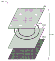
图8描绘根据一些实现方式的包括两个同心SRR的示例开口环谐振器(SRR)配置的自上而下示意图。8 depicts a top-down schematic diagram of an example split ring resonator (SRR) configuration including two concentric SRRs, according to some implementations.
图9描绘根据一些实现方式的示出用于通过基于阻抗的光谱法进行轮胎磨损感测的完整轮胎诊断系统和设备的示意图。9 depicts a schematic diagram illustrating a complete tire diagnostic system and apparatus for tire wear sensing by impedance-based spectroscopy, according to some implementations.
图10和图11描绘根据一些实现方式的与经由遥测传送到导航系统的轮胎信息以及用于制造印刷碳基材料的设备有关的示意图。10 and 11 depict schematic diagrams related to tire information communicated via telemetry to a navigation system and equipment for manufacturing printed carbon-based materials, according to some implementations.
图12描绘根据一些实现方式的通过轮胎胎面层和/或轮胎主体帘布层印刷编码对车辆轮胎的基于谐振序列号的数字编码。12 depicts resonant serial number-based digital encoding of a vehicle tire via tire tread and/or tire body ply printed encoding, according to some implementations.
图13示出根据一些实现方式的促成由不同的近端存在谐振器类型引起的集合现象的谐振机制。13 illustrates resonance mechanisms that contribute to the aggregation phenomenon caused by different proximal presence resonator types, according to some implementations.
图14是根据一些实现方式的包括一个或多个目前公开的SRR的示例温度传感器。14 is an example temperature sensor including one or more of the presently disclosed SRRs, according to some implementations.
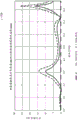
图15是根据一些实现方式的测量谐振签名信号强度(以分贝dB为单位)相对于轮胎胎面层损失的高度(以毫米mm为单位)的曲线图。15 is a graph of measured resonance signature signal strength (in decibels dB) versus height of tire tread layer loss (in millimeters mm), according to some implementations.
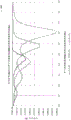
图16是根据一些实现方式的测量谐振签名信号强度(以分贝dB为单位)相对于SRR的固有谐振频率的曲线图,示出了与轮胎帘布层变形成比例的谐振响应位移。16 is a graph of measured resonance signature signal strength (in decibels in dB) versus natural resonance frequency of an SRR showing resonance response displacement proportional to tire ply deformation, according to some implementations.
图17是根据一些实现方式的可对应于编码序列号而谐振的SRR的信号强度相对于线性调频信号频率的曲线图。17 is a graph of signal strength versus chirp frequency for an SRR that may resonate corresponding to an encoded serial number, according to some implementations.
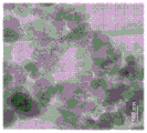
图18A至图18Y描绘根据一些实现方式的用作用于生产任何目前公开的谐振器(例如SRR)的成形材料的碳质材料。18A-18Y depict carbonaceous materials used as forming materials for producing any of the presently disclosed resonators, such as SRRs, according to some implementations.
各种图式中的类似附图标记和名称指示类似元件。Similar reference numbers and names in the various drawings indicate similar elements.
具体实施方式Detailed ways
本文公开的主题的各种实现方式总体上涉及部署由碳质微观结构制成的耐用传感器(例如,开口环谐振器SRR)。所述传感器可以结合到车辆部件内,例如,在常规的目前可市售的气动(指空气、氮气或其他充气)轮胎、下一代无空气实心轮胎的主体的帘布层内,以及在其他位置,例如在车辆车身内。所述传感器可以嵌入在轮胎帘布层和/或轮胎胎面的多个部分内,例如,与路面或地面接触的橡胶。常规轮胎使用会导致接触表面的劣化,最终导致光面(无胎面花纹)轮胎无法充分地粘附到道路表面,尤其在恶劣天气条件(例如,下雪、大雨等)下。含有传感器的轮胎帘布层的劣化产生传感器响应行为的对应的可检测变化,例如,相对于侧向轮胎滑动例如“漂移”(这是一些狂热爱好者团体中的常见操作)中遇到的向前旋转和轮胎应变二者。这样,两种常规(例如,向前旋转)轮胎劣化可通过观测预期传感器谐振响应行为的偏移(例如,如通过下文进一步解释的概念频移-键控来完成)通过预期传感器谐振响应行为的改变和轮胎粘滞力的失去(例如,在漂移操作期间)来检测。如通常所理解,粘滞力可意指为了使接触的静止物体能够发生相对运动而需要克服的静摩擦,例如在涉及侧向移动(诸如漂移)的技能驾驶操作期间可能遇到的情况。这与动摩擦和/或动态摩擦相反,动摩擦和/或动态摩擦可意指二个接触表面之间的同时移动等。Various implementations of the subject matter disclosed herein generally involve deploying durable sensors (eg, split ring resonators, SRRs) made of carbonaceous microstructures. The sensors may be incorporated into vehicle components, for example, within the carcass of conventional currently available pneumatic (referring to air, nitrogen, or other pneumatic) tires, next-generation airless solid tires, and in other locations, For example in the body of a vehicle. The sensors may be embedded within portions of the tire ply and/or the tire tread, for example, the rubber that contacts the road or ground. Conventional tire use can lead to degradation of the contact surface, ultimately resulting in a slick (no tread) tire not adequately adhering to the road surface, especially under adverse weather conditions (eg, snow, heavy rain, etc.). Deterioration of the tire ply containing the sensor produces a corresponding detectable change in sensor response behavior, e.g., relative to lateral tire slippage such as that encountered in "drifting" (a common practice in some enthusiast communities). Both rotation and tire strain. In this way, both conventional (e.g., forward rotating) tire degradations can be accomplished by observing shifts in the expected sensor resonant response behavior (e.g., by the concept frequency shift-keying as explained further below) by shifting the expected sensor resonant response behavior Changes and loss of tire viscosity (for example, during drifting maneuvers) are detected. As commonly understood, viscous forces may mean static friction that needs to be overcome in order to enable relative motion of contacting stationary objects, such as may be encountered during skillful driving maneuvers involving lateral movement, such as drifting. This is in contrast to kinetic and/or dynamic friction, which may mean simultaneous movement between two contacting surfaces, or the like.
碳质材料可在合成期间进行调谐以实现所发射的RF信号的特定的预期射频(RF)信号偏移(指频移)和信号衰减(指信号大小的减小)行为。能够发射RF信号的设备可包括例如收发器,所述收发器安装在装备有所公开系统和/或电感器-电容器(LC)电路(也称为(互换地)储能电路、LC电路或谐振器)的车辆的一个或多个轮窝内。目前公开的实现方式不需要活动部件,因此不太容易由于常规道路使用而磨损和撕裂。SRR与预先存在的车辆电子部件一起起作用。所公开的成分碳质材料的目标RF谐振频率值可在反应腔室或反应器内进行调谐以展现出相互作用而得到目标性能特性。所述特性可用于任何数目的应用,例如多节、低压越野轮胎以及仅用于赛道的无胎面花纹的光面胎。由独特碳质材料形成的SRR在指定射频(RF)(例如0.01GHz至100GHz)下展现出频移和/或信号衰减,所述指定射频可根据期望应用进行调整。关于可调性,碳质材料可在反应器中自含碳气态物质天然生长(例如,自成核),而不需要晶种粒子来产生绚丽的3D结构。Carbonaceous materials can be tuned during synthesis to achieve specific desired radio frequency (RF) signal shift (referring to frequency shift) and signal attenuation (referring to reduction in signal magnitude) behavior of the emitted RF signal. Devices capable of transmitting RF signals may include, for example, transceivers mounted on devices equipped with the disclosed system and/or inductor-capacitor (LC) circuits (also referred to (interchangeably) as tank circuits, LC circuits, or resonator) in one or more wheel wells of the vehicle. The presently disclosed implementation requires no moving parts and is therefore less prone to wear and tear from regular road use. SRRs work with pre-existing vehicle electronics. Target RF resonant frequency values for the disclosed constituent carbonaceous materials can be tuned within a reaction chamber or reactor to exhibit interactions to yield target performance characteristics. The properties can be used in any number of applications, such as knobby, low pressure off-road tires and untreaded slick tires for track only. SRRs formed from unique carbonaceous materials exhibit frequency shifts and/or signal attenuation at specified radio frequencies (RF) (eg, 0.01 GHz to 100 GHz), which can be tuned according to the desired application. With regard to tunability, carbonaceous materials can grow naturally (eg, self-nucleate) from carbon-containing gaseous species in the reactor without the need for seed particles to produce the gorgeous 3D structures.
装备有所公开材料和系统的车辆周围环境的变化(例如,雪、雨等)可能会影响SRR的谐振、频移和/或信号衰减行为。因此,很微小的轮胎条件变化都可以被检测到并传达给驾驶员。例如,如果含有一个或多个SRR的轮胎帘布层接触道路表面(例如,向前旋转)并且由此随时间推移而劣化,则劣化的轮胎帘布层内的该SRR的谐振可能会改变。另外,其他可检测到的变化可能会在漂移(例如,侧向移动)情形期间发生,使得含有SRR的受影响的轮胎帘布层和/或胎面层的信号响应可指示该胎面层的存在或不存在以及磨损程度。因此,SRR可准确地且精确地检测天气或其他环境条件(例如技能驾驶操作)的突然或逐渐转变。Changes in the environment (eg, snow, rain, etc.) surrounding a vehicle equipped with the disclosed materials and systems may affect the resonance, frequency shift, and/or signal attenuation behavior of the SRR. Thus, even the slightest change in tire condition can be detected and communicated to the driver. For example, if a tire ply containing one or more SRRs contacts a road surface (eg, rotates forward) and thereby degrades over time, the resonance of the SRRs within the degraded tire ply may change. Additionally, other detectable changes may occur during a drift (e.g., lateral movement) situation such that the signal response of the affected tire ply and/or tread layer containing the SRR may indicate the presence of the tread layer or not present and the degree of wear. Thus, SRR can accurately and precisely detect sudden or gradual transitions in weather or other environmental conditions, such as skillful driving maneuvers.
可通过使用具有已知频率的电磁(EM)信号刺激每一SRR内的RF谐振材料来检测SRR的RF范围谐振频率响应的可检测到的变化和/或偏移。在一些配置中,EM信号最初可通过天线(也安装在车辆上)输出和/或进一步通过安装在一个或多个轮窝内的图案化谐振电路(本文中也称为“谐振器”,所述谐振电路可以3D打印到轮胎主体帘布层上)传播。这样,可用电子方式观测并分析所发射信号的与相应SRR相关联的衰减和/或频移以计示当前环境条件。另外,可观测RF谐振频率(或多个频率)的变化并与已知且离散的校准点进行比较以确定在给定时刻在车辆车身上的一个或多个限定的检测点处测量的轮胎气压。Detectable changes and/or shifts in the RF range resonant frequency response of the SRRs can be detected by stimulating the RF resonant material within each SRR with an electromagnetic (EM) signal having a known frequency. In some configurations, the EM signal may initially be output via an antenna (also mounted on the vehicle) and/or further passed through a patterned resonant circuit (also referred to herein as a "resonator" herein) mounted within one or more wheel wells, so The resonant circuit described above can be 3D printed onto the tire body ply). In this way, the attenuation and/or frequency shift of the transmitted signal associated with the corresponding SRR can be observed and analyzed electronically to give an indication of the current environmental conditions. Additionally, changes in the RF resonant frequency (or frequencies) can be observed and compared to known and discrete calibration points to determine the tire pressure measured at one or more defined detection points on the vehicle body at a given moment .
轮胎的常规使用(诸如在大多数路面轮胎的道路上行驶或越野轮胎的越野行驶期间遇到的情况)可能会导致轮胎部分的些微变形,这样可能会导致在y被RF信号‘探查’时相应SRR的固有RF谐振频率变化。可检测与形成各种SRR的目前公开的碳相关联的此类固有谐振频率变化并与已知校准点进行比较以确定轮胎内部的条件。将天线与结合到轮胎帘布层内的目前公开的SRR结合使用的系统可适于感测轮胎帘布层性质变化和向车辆中的相关联的遥测设备发出报告。Regular use of the tire (such as encountered during on-road driving with most pavement tires or off-road driving with off-road tires) may cause slight deformation of the tire section, which may result in a corresponding The natural RF resonant frequency of the SRR varies. Such natural resonant frequency changes associated with the presently disclosed carbons forming the various SRRs can be detected and compared to known calibration points to determine conditions inside the tire. A system using an antenna in conjunction with the presently disclosed SRR incorporated into the tire ply may be adapted to sense changes in tire ply properties and report to associated telemetry equipment in the vehicle.
目前公开的SRR可经过调谐以检测相应轮胎帘布层的物理性质的很微小变化,包括由于车辆蒙皮上的气压或由于轮胎中/上的任何外力施加导致的变化。可通过“探查”(例如,发射RF信号并在之后观测和分析RF信号)来检测此类变化,随后处理给定轮胎帘布层、胎面层或其他表面或区域的独特的一组检测到的性质(例如“签名”),如由例如频域回波所展现。讨论了用于校准观测到的信号签名和处理返回签名的各种机制。公开了用于制造具有与弹性体相互作用的被动嵌入式传感器的轮胎的方法,所述传感器呈调谐碳结构的形式。例如,用于由多个帘布层制造轮胎的机制可能会影响SRR的固有谐振频率行为。另外,轮胎可以被构造为包括多个轮胎帘布层,每一轮胎帘布层结合了具有独特的调谐碳质微观结构的不同调谐碳,所述微观结构可以是微米级的,或另选地是纳米、微米、甚至中间粒径一直到毫米(mm)级中的任何一者或多者。The presently disclosed SRRs can be tuned to detect very small changes in the physical properties of the corresponding tire ply, including changes due to air pressure on the vehicle skin or due to any external force application in/on the tire. Such changes can be detected by "probing" (e.g., transmitting an RF signal and then observing and analyzing the RF signal), followed by processing a unique set of detected signals for a given tire ply, tread, or other surface or area. properties (eg "signature") as exhibited by eg frequency domain echoes. Various mechanisms for calibrating observed signal signatures and processing returned signatures are discussed. A method for manufacturing tires with passively embedded sensors interacting with elastomers in the form of tuned carbon structures is disclosed. For example, the mechanisms used to manufacture tires from multiple plies may affect the natural resonant frequency behavior of the SRR. In addition, tires may be constructed to include multiple tire plies, each tire ply incorporating a different tuned carbon with a unique tuned carbonaceous microstructure, which may be micron-scale, or alternatively nanoscale , micron, or even median particle size up to any one or more of millimeter (mm) levels.
所公开的SRR可以实现来自GHz和MHz范围中的谐振的自供电签名,这通过摩擦发电机而成为可能(例如,在例如车辆轮胎旋转以及它与路面或地面反复摩擦和/或接触时产生电流)。此类摩擦部件可集成或以其他方式结合到一个或多个车辆轮胎帘布层中的弹性体层之间的多个钢带内。这样,SRR可通过摩擦发电机充电(和/或供电)以使谐振器谐振(并因此发射RF信号)并放电。谐振器可被配置为适应重复充电-放电循环并且采取各种形状和/或图案中的任何一者或多者,包括具有固有谐振值或性质(基于其成形材料和/或构造)的卵形。The disclosed SRR can achieve a self-powered signature from resonance in the GHz and MHz range, which is made possible by a triboelectric generator (e.g., generating an electrical current when, for example, a vehicle tire rotates and it repeatedly rubs and/or contacts the road or ground ). Such friction components may be integrated or otherwise incorporated into a plurality of steel belts between elastomeric layers in one or more vehicle tire plies. In this way, the SRR can be charged (and/or powered) by the triboelectric generator to cause the resonator to resonate (and thus emit an RF signal) and discharge. The resonator can be configured to accommodate repeated charge-discharge cycles and take any one or more of a variety of shapes and/or patterns, including ovoids with inherent resonant values or properties based on their forming material and/or configuration .
谐振器的形状或取向的变化可能会导致任何相关联谐振常数的对应变化。因此,由变形(例如,在像内部轮胎压力等静态条件下,或在诸如驶过道钉时遇到的那些动态条件等动态条件下)导致的轮胎物理性质的任何变化都可能会改变相应SRR的形状或取向。可使用不同的谐振器图案(例如,除了SRR之外或替代SRR)来对一类变形比对另一类变形以更大的灵敏度作出响应(诸如指在绕着曲线移动时遇到的侧向变形相比于在驶过沙砾或粗糙表面时遇到的垂直运动)。除了SRR基于轮胎变形而改变信号响应行为的配置之外,SRR还可以与其他信号衰减检测能力电子通信,例如,与放置于车轮的轮窝或甚至轮辋内的数字信号处理、DSP、计算机芯片和/或换能器相关联。DSP可与用于刺激和响应的外部收发器(半导体芯片)一起起作用;在可选时。SRR也可与结合到单独轮胎帘布层中的摩擦发电机通信并展现出可通过外部接收器检测的谐振行为。A change in the shape or orientation of a resonator may result in a corresponding change in any associated resonance constant. Therefore, any change in the physical properties of the tire caused by deformation (e.g., under static conditions like internal tire pressure, or under dynamic conditions such as those encountered when driving over road studs) may alter the corresponding SRR's shape or orientation. Different resonator patterns can be used (e.g., in addition to or instead of SRRs) to respond with greater sensitivity to one type of deformation than another (such as a finger's lateral movement encountered when moving around a curve). deformation compared to the vertical motion encountered when driving over gravel or rough surfaces). In addition to the configuration of the SRR to change the signal response behavior based on tire deformation, the SRR can also electronically communicate with other signal attenuation detection capabilities, such as digital signal processing, DSP, computer chips and / or transducer association. DSP can function with external transceiver (semiconductor chip) for stimulus and response; when optional. SRRs can also communicate with triboelectric generators incorporated into individual tire plies and exhibit resonant behavior detectable by external receivers.
图1是例如意欲装备到车辆(诸如汽车和/或卡车)上的车辆条件检测系统1A00的示意图。车辆条件检测系统1A00可包括传感器,诸如调谐RF谐振部件108(例如,开口环谐振器,诸如图8所示的开口环谐振器)。调谐RF谐振部件108中的每一者可由多种碳基微观结构材料、聚集体、聚结物和/或类似者形成,诸如Stowell等人在2020年2月7日提交的标题为“3D Self-Assembled Multi-Modal Carbon-Based Particle”的美国专利申请No.16/785,020中公开的那些材料(统称为“碳质材料”)。调谐RF谐振部件108可结合到车辆(诸如常规的驾驶员驾驶的汽车或能够操作以在无人类驾驶员情况下移动车辆乘员的完全自主运输舱或车辆)上的带传感器104、软管传感器105、轮胎传感器106和收发器天线102中的任何一者或多者中。FIG. 1 is a schematic diagram of a vehicle condition detection system 1A00 intended, for example, to be equipped on a vehicle such as an automobile and/or truck. The vehicle condition detection system 1A00 may include a sensor, such as a tuned RF resonant component 108 (eg, a split ring resonator, such as that shown in FIG. 8 ). Each of the tuning RF resonant components 108 may be formed from a variety of carbon-based microstructural materials, aggregates, agglomerates, and/or the like, such as in a paper by Stowell et al., filed Feb. 7, 2020 entitled "3D Self- - Assembled Multi-Modal Carbon-Based Particle" those materials disclosed in U.S. Patent Application No. 16/785,020 (collectively "carbonaceous materials"). The tuned RF resonant component 108 may be incorporated into a
调谐RF谐振部件108可被配置为诸如通过测量信号频移或衰减来与收发器114、车辆中央处理单元116、车辆传感器数据接收单元118、车辆致动器控制单元120和致动器122中的任何一者或多者电子地和/或无线地通信,所述致动器包括门、窗户、锁125、发动机控制126、导航/抬头显示器128、悬架控制129和气翼装饰件130。调谐RF谐振部件108可经由使用收发器114发射的RF信号110和/或返回的RF信号112导致所发射RF信号的观测到的频率的偏移(被称为“频移”,意指频率的任何变化)。对对应于所发射RF信号110的所返回RF信号112的提及可以是指相对于集成到带传感器104和/或类似者中的任何一者或多者中的调谐RF谐振部件108中的一者或多者的对所发射RF信号110的频移或衰减的电子检测(例如,不是来自传感器的信号的实际物理反射或返回)。所发射RF信号110和所返回RF信号112可与车辆中央处理单元116、车辆传感器数据接收单元118、车辆致动器控制单元120和/或致动器122中的任何一者或多者通信(并且因此也通过以上各者评定)。车辆条件检测系统100可使用软件与硬件的任何合适组合来实施。The tuned RF resonant component 108 may be configured to communicate with the
车辆条件检测系统100的所描绘的各种传感器中的任何一者或多者可由被调谐以在被所发射RF信号“探查”(指被撞击或以其他方式接触)时实现特定RF谐振行为的碳基微观结构形成。车辆条件检测系统100(或其任何方面)可被配置为在任何设想到的车辆使用应用、领域或环境中实施,诸如在恶劣的天气条件期间,包括雨夹雪、冰雹、下雪、结冰、霜冻、泥浆、沙石、碎屑、不平坦地形、水和/或其类似者。Any one or more of the various depicted sensors of the vehicle
调谐RF谐振部件108可安置在车辆周围和/或上(诸如在驾驶室、发动机舱或行李箱内或在车身上)。如图1A所示,调谐RF谐振部件可包括带传感器104、软管传感器105、轮胎传感器106和收发器天线102,其中任何一者或多者可在车辆生产期间在现代车辆中实施,或(另选地)改装到预先存在的车辆,不管所述预先存在的车辆的年龄和/或条件如何。调谐RF谐振部件108可部分地使用容易得到的材料形成,诸如玻璃纤维(诸如用于气翼)或橡胶(诸如用于轮胎)或玻璃(诸如用于挡风玻璃)。这些常规材料可以与碳基材料、生长物、聚结物、聚集体、薄片、粒子和/或其类似者组合,诸如在反应腔室或反应器中由含碳气态物质在操作中自成核并且被调配为实现以下各项的那些物质:(1)提高它们结合到其中的复合材料的机械(诸如拉伸、压缩、剪切、应变、变形和/或类似者)强度;和/或(2)在一个特定频率或一组特定频率(在10GHz至100GHz的范围内)下谐振。主导材料的RF谐振性质和行为的变量可与负责控制材料强度的变量分开控制。The tuning RF resonant component 108 may be positioned around and/or on the vehicle (such as in the cabin, engine compartment or trunk or on the vehicle body). As shown in FIG. 1A, the tuned RF resonant components may include a
基于射频(RF)的刺激(诸如由收发器114发射或由谐振器发射)可用于向调谐RF谐振部件108、致动器122(和/或类似者,诸如实施在调谐RF谐振部件108中或上的传感器)发射RF信号,以检测其相应的谐振频率以及在所发射信号(其可能受内部或外部条件影响)的衰减中观测到的频移和型样。例如,如果调谐RF谐振部件(诸如轮胎传感器106)已经过特别准备(被称为“调谐”)以在约3的频率下谐振,那么轮胎传感器106可在通过3GHz RF信号刺激时发射交感谐振或交感振动(指谐波现象,其中先前被动的线或振动体对与其具有谐波相似性的外部振动作出响应)。Radio frequency (RF) based stimuli (such as transmitted by
这些交感振动可在刺激频率处发生以及在源自基本3GHz音调的泛音或旁瓣中发生。如果(调谐RF谐振部件108中的)调谐谐振部件已被调谐为在2GHz下谐振,那么在调谐谐振部件通过2GHz RF信号刺激时,该调谐谐振部件将发射所描述的交感振动。这些交感振动将在刺激频率处以及在源自基本2GHz音调的泛音或旁瓣(在工程学中,指天线或其他辐射源的远场辐射型样的并非主瓣的局部最大值)中发生。许多的额外调谐谐振部件可位于RF发射器的近侧。RF发射器可能被控制为首先发射2GHz声脉冲,接着发射3GHz声脉冲,接着发射4GHz声脉冲等等。处于不同且递增的频率的该一连串声脉冲可被称为“线性调频脉冲”。These sympathetic vibrations can occur at the stimulating frequency as well as in overtones or sidelobes derived from the fundamental 3GHz tone. If the tuning resonant element (of tuning RF resonant element 108 ) has been tuned to resonate at 2 GHz, then the tuned resonant element will emit the described sympathetic vibrations when stimulated by a 2 GHz RF signal. These sympathetic vibrations will occur at the stimulating frequency as well as in overtones or sidelobes (in engineering, local maxima other than the main lobe of the far-field radiation pattern of an antenna or other radiation source) originating from the fundamental 2GHz tone. A number of additional tuned resonant components can be located near the RF transmitter. The RF transmitter may be controlled to emit a 2GHz sound pulse first, then a 3GHz sound pulse, then a 4GHz sound pulse, and so on. This train of sound pulses at different and increasing frequencies may be referred to as a "chirp".
轮胎主体(诸如大体上由图3F1至图3F2示出)内的相邻轮胎帘布层(诸如彼此接触的轮胎帘布层)可具有不同浓度水平或构型的碳基微观结构,以限定结合在该(指相应)轮胎主体帘布层和/或胎面层内的传感器在彼此并非谐波的不同的相异频率下谐振。也就是说,非谐波帘布层可确保特定轮胎主体帘布层和/或胎面层(或其他表面或材料)相对于其他层的相异且可容易辨识的检测,其中由于由谐波引起(或以其他方式与谐波相关联)的信号干扰导致的混淆风险最小。Adjacent tire plies (such as tire plies in contact with each other) within a tire body (such as generally shown in FIGS. (Referring to corresponding) The sensors within the tire body ply and/or tread resonate at different distinct frequencies that are not harmonics of each other. That is, non-harmonic plies can ensure distinct and easily identifiable detection of a particular tire body ply and/or tread layer (or other surface or material) relative to other layers, where due to harmonics ( or otherwise associated with harmonics) presents minimal risk of confusion due to signal interference.
收发器114(和/或谐振器,图1A中未示出)可被配置为将所发射RF信号110传输到调谐RF谐振部件108中的任何一者或多者,从而以数字方式辨识从调谐RF谐振部件108中的任何一者或多者返回的RF信号112的频移和/或衰减。此类“返回”信号112可被处理为可电子地传送到车辆中央处理单元116的数字信息,所述车辆中央处理单元与车辆传感器数据接收单元118和/或车辆致动器控制单元120相互作用,所述车辆传感器数据接收单元和/或车辆致动器控制单元基于接收到的传感器数据来发送其他车辆性能相关信号。所返回信号1120可至少部分地控制致动器122。也就是说,车辆致动器控制单元120可控制致动器122来根据从车辆传感器数据接收单元118接收到的关于由与收发器114通信的调谐RF部件指示的车辆部件磨损或劣化的反馈来操作门、窗户、锁124、发动机控制126、导航/抬头显示器128、悬架控制129和/或气翼装饰件130中的任何一者或多者。The transceiver 114 (and/or the resonator, not shown in FIG. 1A ) may be configured to transmit the transmitted RF signal 110 to any one or more of the tuned RF resonant components 108 to digitally identify the tuned Frequency shifting and/or attenuation of the RF signal 112 returned by any one or more of the RF resonating components 108 . Such "return" signals 112 may be processed into digital information that may be transmitted electronically to a vehicle central processing unit 116 that interacts with a vehicle sensor
在监测所返回RF信号111的行为(诸如频移和/或衰减)时检测到道路碎屑和恶劣的天气条件可能会例如导致致动器122触发悬架控制129的相应变化。此类变化可例如包括使悬架设置变软以适应驶过道路碎屑,而在之后使悬架设置收紧以适应增强的车辆响应性,增强的车辆响应性在大雨(并且因此牵引力低)条件期间行驶可能是必要的。车辆致动器控制单元120进行的此类控制的变化有很多,其中车辆外部的任何可设想到的条件可通过收发器检测到(如所发射RF信号110和/或所返回RF信号112的频移和/或衰减所展现)。Detection of road debris and adverse weather conditions while monitoring the behavior of the returned RF signal 111 , such as frequency shift and/or attenuation, may, for example, cause the actuator 122 to trigger a corresponding change in the suspension control 129 . Such changes may include, for example, softening the suspension settings to accommodate driving over road debris, and tightening the suspension settings afterwards to accommodate enhanced vehicle responsiveness in heavy rain (and thus low traction) Driving during conditions may be necessary. There are many variations of such control by the vehicle actuator control unit 120, wherein any conceivable condition external to the vehicle can be detected by the transceiver (such as the frequency of the transmitted RF signal 110 and/or the returned RF signal 112). shift and/or attenuation).
形成所描述传感器的调谐RF谐振部件108中的任一者可经过调谐以在被刺激时在特定频率下谐振,其中一个或多个频率的所限定位移(如由碳基微观结构所引起)可形成指示传感器结合到其中的材料或材料的条件的一个或多个信号签名。Any of the tuned RF resonant components 108 forming the described sensor may be tuned to resonate at a particular frequency when stimulated, wherein a defined displacement of one or more frequencies (as induced by the carbon-based microstructure) may One or more signal signatures are formed indicative of the material or condition of the material into which the sensor is incorporated.
所返回RF信号112中的频移(诸如信号签名中所示的频移)的时间方差或偏差(TDEV)(指相位x对比测量的时钟源的观测间隔τ的时间稳定性;时间偏差因此形成测量的标准偏差类型以指示信号源的时间不稳定性)可对应于传感器环境的时变变化和/或传感器自身的时变变化。因此,信号处理系统(诸如,车辆中央处理单元116、车辆传感器数据接收单元118和/或车辆致动器控制单元120等中的任何一者或多者)可被配置为根据TDEV原理分析与所述传感器相关联的信号(诸如所发射RF信号110和所返回RF信号112)。此类分析(诸如签名分析)的结果可被递送到车辆中央处理单元116,所述车辆中央处理单元(转而)可向车辆致动器控制单元120传达命令以作出适当的响应动作。在一些配置中,致动器122作出的此类响应动作可涉及至少一些人类驾驶员输入,而在其他配置中,车辆条件检测系统100可完全以自含式方式起作用,从而允许如此装备的车辆在完全无人驾驶环境中出现部件性能问题时解决所述问题。另外,车辆中央处理单元116可与一个或多个上游部件(例如,容纳于静止区域中的与赛车应用相关联的计算设备)和/或负责取得和/或处理与调谐RF谐振部件108相关联的所有数据的赛车任务控制单元119电子地通信。The time variance or deviation (TDEV) (TDEV) of a frequency shift (such as that shown in the signal signature) in the returned RF signal 112 (refers to the temporal stability of phase x versus the observation interval τ of the measured clock source; the time deviation thus forms The type of standard deviation measured to indicate temporal instability of the signal source) may correspond to time-varying changes in the sensor environment and/or time-varying changes in the sensor itself. Therefore, the signal processing system (such as any one or more of the vehicle central processing unit 116, the vehicle sensor
图2示出信号处理系统200的框图,所述信号处理系统可包括表面传感器260和嵌入式传感器270,所述传感器中的任何一者或多者可与其他传感器就如此装备的车辆(指装备有表面传感器260和嵌入式传感器270的车辆)的环境变化250进行电子通信。信号处理系统200还可以包括收发器214、签名分析模块254和车辆中央处理单元216,以上各者中的任何一者或多者与其他者电子通信。2 shows a block diagram of a
在一些实现方式中,嵌入式传感器270(其可嵌入于诸如轮胎帘布层等材料内)可采用自供电遥测和/或通过自供电遥测供电,所述自供电遥测包括也结合到围封相应传感器的材料内的摩擦能产生器(图2中未示出)。因此,摩擦能产生器可通过收集在例如旋转中的轮胎或车轮与它接触的路面之间累积的静电荷来产生可用的电流和/或电力,以对谐振电路供电(将在本文中更详细地描述),所述谐振电路随后可谐振以发射已知频率的RF信号。因此,安装在外部的收发器单元(诸如安装在车辆的每一轮窝内的收发器单元)可发射RF信号,所述RF信号通过谐振电路进一步传播,所述谐振电路在此配置中是摩擦供电的并嵌入于轮胎主体的帘布层中。所发射信号的频移和/或大小衰减同样例如由签名分析模块254和/或车辆中央处理单元216接收并分析。In some implementations, embedded sensors 270 (which may be embedded within materials such as tire ply) may employ and/or be powered by self-powered telemetry including sensors that are also incorporated into the enclosure. Frictional energy generators within the material (not shown in Figure 2). Thus, the frictional energy generator may generate current and/or electricity usable to power a resonant circuit (discussed in more detail herein) by collecting static charge accumulated between, for example, a rotating tire or wheel and the road surface it is in contact with. described), the resonant circuit may then resonate to transmit an RF signal of known frequency. Thus, an externally mounted transceiver unit, such as a transceiver unit mounted in each wheel well of the vehicle, can transmit an RF signal that propagates further through a resonant circuit, which in this configuration is a friction Powered and embedded in the ply of the tire body. The frequency shift and/or magnitude attenuation of the transmitted signal is also received and analyzed, for example, by the
自供电遥测(指在远处或不可接近的点处收集测量结果或其他数据并将其自动传输到接收设备以进行监测)可结合到车辆轮胎中。如本文所提及,自供电遥测包括利用轮胎内部的摩擦电荷产生、该电荷的存储和所存储的电荷之后放电到谐振电路或通过谐振电路放电,以利用在谐振电路(指由由字母L表示的电感器和由字母C表示的电容器连接在一起而组成的电路,用于产生处于一个或多个特定频率的RF信号)放电期间发生的“振铃”(指负责RF信号的进一步发射的谐振电路的振荡)。Self-powered telemetry (meaning that measurements or other data are collected at a remote or inaccessible point and automatically transmitted to a receiving device for monitoring) could be incorporated into vehicle tires. As referred to herein, self-powered telemetry involves the use of triboelectric charge generation inside the tire, the storage of this charge and the subsequent discharge of the stored charge to or through a resonant circuit to utilize the A circuit consisting of an inductor and a capacitor denoted by the letter C connected together to generate an RF signal at one or more specific frequencies) "ringing" that occurs during discharge (referring to the resonance responsible for the further emission of the RF signal circuit oscillation).
可大体上在目前公开的车辆部件磨损检测系统的两种可能配置中的一者中提供声脉冲刺激,所述两种可能配置包括:依赖于由刺激源产生的信号或‘声脉冲’,所述刺激源诸如位于轮胎(或意欲用于监测由于持续使用导致的磨损的其他车辆部件)外部(诸如结合到如此装备的车辆的每一轮窝内)的常规收发器;或使用轮胎内(指也嵌入于轮胎帘布层中,与具有碳基微观结构的传感器类似)摩擦能量产生装置,所述摩擦能量产生装置收集由旋转中的车轮和/或轮胎与其所接触的地面或路面之间的原本会浪费掉的摩擦能量产生的能量。如通常所理解和本文所提及的,摩擦学意指对在相对运动中的相互作用表面的科学和工程技术的研究。此类摩擦能量产生装置可将电能提供到轮胎内谐振装置,所述轮胎内谐振装置转而自发射轮胎性质遥测。Acoustic pulse stimulation may generally be provided in one of two possible configurations of the presently disclosed vehicle component wear detection system including: relying on a signal or 'sound pulse' generated by a stimulus source, the Such stimulus sources as conventional transceivers located external to the tire (or other vehicle component intended for monitoring wear due to continued use), such as incorporated into each wheel well of a vehicle so equipped; or using internal tires (referred to as Also embedded in the tire ply, similar to sensors with carbon-based microstructures) frictional energy generating devices that collect the original Energy generated from frictional energy that would be wasted. Tribology, as commonly understood and referred to herein, means the scientific and engineering study of interacting surfaces in relative motion. Such a frictional energy generating device may provide electrical energy to an in-tire resonant device which in turn self-transmits tire property telemetry.
上述两个‘声脉冲’刺激产生器或提供者中的任一者可具有范围在约10GHz至99GHz的复谐振频率(CRf)分量(例如,由于小尺寸的结构如石墨烯片的谐振频率)以及由相对大尺寸的所述轮胎内谐振导致的在Khz范围内的较低频率谐振。大体上,CRf可等同于弹性体部件固有谐振频率、碳部件固有谐振频率、构成部件的比率/集合和轮胎内谐振装置的几何形状的函数。Either of the above two 'acoustic pulse' stimulus generators or providers may have a complex resonant frequency (CRf) component in the range of about 10 GHz to 99 GHz (e.g. due to the small size of the resonant frequency of structures such as graphene sheets) And the lower frequency resonances in the Khz range caused by said internal resonances of relatively large size. In general, CRf can be equated as a function of the natural resonant frequency of the elastomeric component, the natural resonant frequency of the carbon component, the ratio/collection of constituent components, and the geometry of the resonant device within the tire.
一旦由碳基微观结构形成的传感器被刺激时,信号处理系统200用于分析信号签名(通过数字地观测所发射RF信号210和/或所返回RF信号212中的任何一者或多者的频移和/或衰减来限定)。由于利用在线性调频脉冲/声脉冲频率中的一者下谐振的线性调频脉冲信号传感器的刺激,通过在其对应的调谐频率处或附近谐振、使所发射频率偏移和/或使所发射信号的振幅衰减来作出“响应”。当在发射线性调频脉冲/声脉冲时发生环境变化(诸如导致轮胎主体帘布层和/或胎面层磨损的环境变化)时,可监测“所返回”信号是否发生调制变化--比调谐频率高或低。因此,收发器214可被配置为接收所返回RF信号212,所述所返回RF信号表示它们撞击到的表面等。Once the sensor formed from the carbon-based microstructure is stimulated, the
前述线性调频脉冲/声脉冲信号可由收发器214发射(诸如通过不可听RF信号、脉冲、振动和/或类似传输)。此外,“返回”信号可由收发器214接收。如图所示,线性调频脉冲信号可按重复的线性调频脉冲序列发生(诸如所发射RF信号210)。例如,线性调频脉冲信号序列可能是由包括1GHz声脉冲、接着是2GHz声脉冲、接着是3GHz声脉冲等的模式形成。整个线性调频脉冲信号序列可整体上连续地重复。在各声脉冲之间可存在短暂的时段,使得来自谐振材料的返回信号(所返回RF信号212)可在声脉冲结束之后立刻被接收到。另选地或另外地,对应于声脉冲刺激的信号和所观测的“响应”的信号可同时发生和/或沿着相同的一般路径或路线发生。签名分析模块可采用数字信号处理技术来将所观测的“响应”的信号与声脉冲信号区分开。在所返回的响应包括跨越许多不同频率(诸如泛音、旁瓣等)的能量的情形中,可使用陷波滤波器来对刺激进行滤波。由收发器接收的所返回信号可被发送到签名分析模块254,所述签名分析模块转而可将处理后的信号发送到车辆中央处理单元216。图2的前述讨论包括对由含碳调谐谐振材料形成的传感器的讨论并且也还可以指感测层压板。The aforementioned chirp/burst signals may be transmitted by the transceiver 214 (such as via inaudible RF signals, pulses, vibrations, and/or similar transmissions). Additionally, a “return” signal may be received by
所公开的传感器可结合到轮胎层中,例如,包括可在轮胎帘布层内的额外碳纤维层之间有间隙地分层的树脂层。每一含碳树脂层可不同地进行调配以在不同的预期或期望调谐频率下谐振。可相对于对应的分子组成来描述材料谐振的物理现象。例如,具有第一限定结构(诸如第一分子结构)的层将在第一频率下谐振,而具有第二、不同的分子结构的层可在第二、不同的频率下谐振。The disclosed sensors may be incorporated into tire layers, for example, including resin layers that may be layered with gaps between additional carbon fiber layers within the tire ply. Each carbon-containing resin layer can be tuned differently to resonate at a different intended or desired tuning frequency. The physical phenomenon of material resonance can be described with respect to the corresponding molecular composition. For example, a layer with a first defined structure (such as a first molecular structure) will resonate at a first frequency, while a layer with a second, different molecular structure may resonate at a second, different frequency.
具有特定分子结构且包含于一层中的材料在该层处于低能态时将在第一调谐频率下谐振,并且在该层中的材料处于诱发的高能态时将在第二不同频率下谐振。例如,一层中的展现出特定分子结构的材料可被调谐为在该层处于固有的、未变形的低能态时在3GHz下谐振。相比之下,在该层相对于其固有的、未变形的低能态至少部分变形时,该层可在2.95GHz下谐振。因此,此现象可经过调整以适应以高保真度和精确度检测例如与道路表面(诸如路面)接触并在某一局部接触区域处经历增强磨损的轮胎表面的最微小的异常的需要。在要求严格的赛道(指具有急转弯和快速高度变化的高技术、多风赛道)上比赛的赛车可受益于此类局部轮胎磨损或劣化信息,以便做出明智的轮胎更换决策,即使在对时间敏感的比赛日条件下也是如此。A material having a particular molecular structure contained in a layer will resonate at a first tuned frequency when the layer is in a low energy state, and will resonate at a second, different frequency when the material in the layer is in an induced high energy state. For example, a material in a layer exhibiting a particular molecular structure can be tuned to resonate at 3 GHz when the layer is in its intrinsic, undeformed, low energy state. In contrast, the layer can resonate at 2.95 GHz when the layer is at least partially deformed relative to its intrinsic, undeformed low energy state. Thus, this phenomenon can be tuned to the need to detect with high fidelity and accuracy the slightest anomaly of eg a tire surface that is in contact with a road surface such as a pavement and experiences increased wear at some localized contact area. Cars racing on demanding tracks (high-tech, windy tracks with sharp turns and rapid altitude changes) can benefit from such localized tire wear or degradation information to make informed tire replacement decisions, even if The same is true in time-sensitive race day conditions.
参看图2B1至图2B2示出及讨论了上文提及的频移现象(诸如从在3GHz的频率下谐振转变为在2.95GHz的频率下谐振)。图2B2描绘了在包含含碳调谐谐振材料的感测层压板中展现出的频移现象。原子发射处于给定元素的固有频率的电磁辐射。也就是说,特定元素的原子具有对应于所述原子的特性的固有频率。例如,当刺激铯原子时,价电子从较低能态(诸如基态)跳跃到较高能态(诸如激发能态)。当电子返回到其较低能态时,其发射呈光子形式的电磁辐射。对于铯,发射的光子在微波频率范围内;为9.192631770THz。比原子大的结构(诸如由多个原子形成的分子)也在可预测频率下谐振(诸如通过发射电磁辐射)。例如,一大堆液态水在109.6THz下谐振。处于张力(诸如,处于块体表面,在各种表面张力状态下)的水在112.6THz下谐振。碳原子和碳结构也展现出取决于所述结构的固有频率。例如,碳纳米管(CNT)的固有谐振频率取决于CNT的管直径和长度。在受控条件下生长CNT以控制管直径和长度导致控制所述结构的固有谐振频率。因此,合成或以其他方式“生长”CNT是调谐到期望谐振频率的一种方式。The frequency shift phenomenon mentioned above (such as a transition from resonance at a frequency of 3 GHz to resonance at a frequency of 2.95 GHz) is shown and discussed with reference to FIGS. 2B1-2B2 . Figure 2B2 depicts the frequency shift phenomenon exhibited in sensing laminates containing carbon-containing tuned resonant materials. Atoms emit electromagnetic radiation at the natural frequency of a given element. That is, atoms of a particular element have natural frequencies corresponding to the properties of the atoms. For example, when a cesium atom is stimulated, valence electrons jump from a lower energy state (such as a ground state) to a higher energy state (such as an excited energy state). When the electron returns to its lower energy state, it emits electromagnetic radiation in the form of photons. For cesium, the emitted photons are in the microwave frequency range; 9.192631770 THz. Structures larger than atoms, such as molecules formed from multiple atoms, also resonate at predictable frequencies (such as by emitting electromagnetic radiation). For example, a mass of liquid water resonates at 109.6 THz. Water in tension (such as at the surface of a bulk, at various states of surface tension) resonates at 112.6 THz. Carbon atoms and carbon structures also exhibit natural frequencies that depend on the structure. For example, the natural resonance frequency of carbon nanotubes (CNTs) depends on the tube diameter and length of the CNTs. Growing CNTs under controlled conditions to control tube diameter and length results in control of the natural resonant frequency of the structure. Therefore, synthesizing or otherwise "growing" CNTs is one way to tune to a desired resonant frequency.
由碳形成的其他结构可在受控条件下形成。此类结构包括但不限于碳纳米洋葱(CNO)、碳晶格、石墨烯、含碳聚集体或聚结物、基于石墨烯的其他含碳材料、工程化纳米级结构等和/或其组合,根据目前公开的实现方式,所述结构中的任一者结合到车辆部件的传感器中。此类结构可被形成为在特定调谐频率下谐振,和/或此类结构可在后处理中进行修改以获得期望的特性或性质。例如,可通过选择材料的组合比率和/或通过添加其他材料来实现期望性质,诸如高增强值。此外,多个此类结构的共同定位引入了其他谐振效应。例如,两个石墨烯薄片可在其之间在一频率下谐振,所述频率取决于薄片的长度、宽度、间距、间距形状和/或其他物理特性和/或其彼此并置。Other structures formed from carbon can form under controlled conditions. Such structures include, but are not limited to, carbon nano-onions (CNO), carbon lattices, graphene, carbon-containing aggregates or agglomerates, graphene-based other carbon-containing materials, engineered nanoscale structures, etc., and/or combinations thereof , according to the presently disclosed implementation, any of the structures is incorporated into a sensor of a vehicle component. Such structures can be formed to resonate at a particular tuning frequency, and/or such structures can be modified in post-processing to obtain desired characteristics or properties. For example, desired properties, such as high reinforcement values, can be achieved by selecting a combination ratio of materials and/or by adding other materials. Furthermore, the co-location of multiple such structures introduces additional resonance effects. For example, two graphene sheets may resonate between them at a frequency that depends on the length, width, pitch, pitch shape, and/or other physical properties of the sheets and/or their juxtaposition to each other.
如本领域中已知的,材料具有特定的可测量特性。这对于天然存在的材料以及对于工程化碳同素异形体都成立。此类工程化的碳同素异形体可经过调谐以展现出物理特性。例如,碳同素异形体可被工程化以展现出对应于以下各者的物理特性:(a)构成初级粒子的特定构型;(b)聚集体形成;和(c)聚结物形成。这些物理特性中的每一者影响使用对应特定碳同素异形体形成的材料的特定谐振频率。As is known in the art, materials have specific measurable properties. This is true for naturally occurring materials as well as for engineered carbon allotropes. Such engineered carbon allotropes can be tuned to exhibit physical properties. For example, carbon allotropes can be engineered to exhibit physical properties corresponding to: (a) specific configurations of constituent primary particles; (b) aggregate formation; and (c) agglomerate formation. Each of these physical properties affects a particular resonant frequency using a material formed with a corresponding particular carbon allotrope.
除了针对对应于特定谐振频率的特定物理配置调谐特定碳基结构之外,还可以将含碳化合物调谐到特定的一个谐振频率(或一组谐振频率)。一组谐振频率被称为谐振特征曲线。被调谐为在被RF信号探查时展现出特定谐振频率的含碳材料(诸如包括碳基微观结构的含碳材料)可通过调整组成所述材料的特定化合物以具有特定电阻抗来进行调谐以展现出特定的谐振特征曲线。不同的电阻抗转而对应于不同的频率响应特征曲线。In addition to tuning a particular carbon-based structure for a particular physical configuration corresponding to a particular resonant frequency, it is also possible to tune a carbon-containing compound to a particular one of the resonant frequencies (or set of resonant frequencies). A set of resonance frequencies is called a resonance characteristic curve. A carbonaceous material tuned to exhibit a particular resonant frequency when probed by an RF signal, such as a carbonaceous material comprising a carbon-based microstructure, can be tuned to exhibit a particular electrical impedance by tuning the particular compounds that make up the material to have a particular electrical impedance A specific resonance characteristic curve is obtained. Different electrical impedances in turn correspond to different frequency response characteristic curves.
阻抗描述了交变(AC)电流流过元件的困难程度。在频域中,由于结构表现为电感器,因此阻抗是具有实数部分和虚数部分的复数。虚数部分是有感电抗(电路元件由于该元件的电感和电容而抵抗电流流动;如果施加相同的电压,较大的电抗会导致较小的电流)分量XL,所述分量是基于特定结构的频率f和电感L:Impedance describes how difficult it is for alternating (AC) current to flow through a component. In the frequency domain, since the structure behaves as an inductor, the impedance is a complex number with real and imaginary parts. The imaginary part is the inductive reactance (a circuit element resists current flow due to the inductance and capacitance of the element; a greater reactance results in a smaller current if the same voltage is applied) component X L , which is based on the specific structure Frequency f and inductance L:
XL=2πfL (方程1)X L =2πfL (equation 1)
随着所接收频率增大,电抗也增大,使得在某一频率阈值下,所发射信号的测量强度(振幅)可衰减。电感L受材料的电阻抗Z影响,其中Z通过以下关系与磁导率μ和电容率ε的材料性质相关:As the received frequency increases, the reactance also increases, so that at a certain frequency threshold, the measured strength (amplitude) of the transmitted signal may attenuate. The inductance L is affected by the electrical impedance Z of the material, where Z is related to the material properties of magnetic permeability μ and permittivity ε by the following relationship:

因此,材料性质的调谐改变电阻抗Z,从而影响电感L并因此影响电抗XL。Thus, tuning of the material properties changes the electrical impedance Z, thereby affecting the inductance L and thus the reactance X L .
具有不同电感的含碳结构(诸如Anzelmo等人在2019年10月1日发布的标题为“Carbon and Elastomer Integration”的美国专利第10,428,197号中公开的那些含碳结构,所述美国专利以全文引用方式并入本文中)可展现出不同的频率响应(在用于产生用于前述系统的传感器时)。也就是说,相较于具有较低电感的另一种含碳结构,具有高电感L(基于电阻抗Z)的含碳结构将在较低频率下达到某一电抗。Carbon-containing structures with different inductances, such as those disclosed in U.S. Patent No. 10,428,197, entitled "Carbon and Elastomer Integration," issued October 1, 2019 to Anzelmo et al., which is incorporated by reference in its entirety methods incorporated herein) may exhibit different frequency responses (when used to create sensors for the aforementioned systems). That is, a carbon-containing structure with a high inductance L (based on electrical impedance Z) will reach a certain reactance at a lower frequency than another carbon-containing structure with a lower inductance.
当对化合物进行调配以调谐到特定电阻抗时,还可以考虑磁导率、电容率和电导率等材料性质。此外,观察到,当该结构处于张力诱发条件下时,诸如当结构稍微变形时(诸如,由此稍微改变结构的物理特性),第一含碳结构将在第一频率下谐振,而第二含碳结构将在第二频率下谐振。Material properties such as magnetic permeability, permittivity, and electrical conductivity can also be considered when formulating compounds to tune to a specific electrical impedance. Furthermore, it was observed that when the structure is under tension-inducing conditions, such as when the structure is slightly deformed (such as thereby slightly changing the physical properties of the structure), the first carbon-containing structure will resonate at a first frequency, while the second The carbon-containing structure will resonate at the second frequency.
示例含碳结构(例如,如图19至图16Y中所示)可在第一频率下谐振,所述第一频率可与包括电容器C1和电感器L1的等效电路相关。频率f1由以下方程给出:An example carbon-containing structure (eg, as shown in FIGS. 19-16Y ) can resonate at a first frequency, which can be related to an equivalent circuit including capacitor C 1 and inductor L 1 . The frequency f1 is given by the following equation:

含碳结构的变形可转而改变结构的电感和/或电容。所述变化可能与包括电容器C2和电感器L2的等效电路相关。频率f2由以下方程给出:Deformation of the carbon-containing structure can in turn change the inductance and/or capacitance of the structure. The variation may be related to an equivalent circuit comprising capacitor C2 and inductor L2 . The frequency f2 is given by the following equation:

图3示出处理从由含碳调谐谐振材料形成的传感器接收到的信号的签名分类系统300。签名分类系统300可在任何物理环境或天气条件中实施。图3是关于将调谐谐振感测材料结合到汽车部件中以用于分类由安装在车辆中的传感器检测、分类和/或从所述传感器接收到的信号(诸如签名)。在操作302处发射处于所选声脉冲频率的声脉冲信号。声脉冲信号产生机制和声脉冲发射机制可通过任何已知技术执行。例如,发射器模块可产生3GHz的所选频率,并且使用一个天线或多个天线来辐射该信号。调谐天线(诸如安装在轮窝或车辆中的任何一者或多者上和/或内)的设计和位置可对应于任何调谐天线几何形状、材料和/或位置,使得声脉冲的强度足以在接近传感器中诱发(RF)谐振。若干调谐天线安置在接近于对应传感器的结构构件上或内。因而,当近侧表面传感器被声脉冲刺激时,近侧表面传感器通过签名反向谐振。该签名可被接收(操作304)并存储在包括所接收到的签名310的数据库中。可在循环中重复发射声脉冲再接着接收签名的序列。FIG. 3 illustrates a
可在反复通过所述循环时改变声脉冲频率(操作308)。因此,当在所述循环中执行操作304时,操作304可存储签名312,包括第一签名3121、第二签名3122一直到第N个签名312N。可通过决策306控制迭代次数。在采取决策306的“否”分支时(诸如,在没有其他额外的声脉冲要发射时),则可将所接收的签名提供(操作314)到数字信号处理模块(诸如,图1B所示的签名分析模块154的实例)。所述数字信号处理模块对照一组校准点318对签名分类(操作316)。所述校准点可被配置为对应于特定的声脉冲频率。例如,校准点288可包括可对应于接近3GHz的第一声脉冲和第一返回签名的第一校准点2881、可对应于接近2GHz的第二声脉冲及第二返回签名的第二校准点2882以及对于任何整数值“N”个校准点以此类推。The acoustic pulse frequency may be varied while iterating through the loop (operation 308). Thus, when the
在操作320处,将已分类信号发送到车辆中央处理单元(诸如图1B的车辆中央处理单元116)。已分类信号可通过车辆中央处理单元中继到托管计算机化数据库的上游存储库,所述计算机化数据库被配置为托管和/或运行机器学习算法。因此,可捕获与信号、已分类信号和信号响应相关的大量刺激以用于后续资料聚集和处理。所述数据库可在计算上做好准备,被称为“训练”,被提供给定的一组感测测量结果,所述测量结果可能与关于车辆性能(诸如由于反复使用导致的轮胎劣化)的条件或诊断相关。如果在车辆的操作期间气翼部件的特定部分的所测量偏转(诸如气压)与气翼部件的不同部分的测量偏转(诸如气压)不同,则潜在的诊断可能是一个轮胎充气不足,因此使得车辆行驶高度不均匀,从而导致车辆上方、上和/或周围的气流展现出成比例的不均匀性,如通过气翼部件上的偏转检测到。其他潜在的条件或诊断也可通过机器学习系统确定。所述条件和/或诊断和/或支持数据可被返回到车辆以完成反馈循环。车辆中的仪器提供可被(诸如驾驶员或工程师)作用的可视化。At
图4示出与将调谐谐振感测材料结合到汽车部件(诸如轮胎)中有关的各种物理特性或方面(轮胎条件参数400)。此处,关于解决可持续传感器在轮胎(包括非气动轮胎和气动轮胎)中的部署来呈现该图。轮胎的构造可对应于子午线轮胎、斜交帘布轮胎、无内胎轮胎、实心轮胎、低压安全轮胎等。轮胎可用于任何种类的车辆和/或关于车辆的设备和/或配件中。此类车辆可包括飞机、全地形车辆、汽车、施工设备、自卸车、推土机、农用设备、叉车、高尔夫球车、收割机、起重卡车、轻便摩托车、摩托车、越野车、赛车、割草机、牵引车、拖车、卡车、轮椅等。除了所呈现的车辆之外或替代所呈现的车辆,轮胎还可以用于非机动车辆、设备和配件中,诸如脚踏车、三轮车、单轮车、割草机、轮椅、推车等。FIG. 4 illustrates various physical characteristics or aspects (tire condition parameters 400 ) related to the incorporation of tuned resonant sensing materials into automotive components, such as tires. Here, the figure is presented with respect to addressing the deployment of sustainable sensors in tires, both non-pneumatic and pneumatic. The configuration of the tire may correspond to radial tires, bias ply tires, tubeless tires, solid tires, safety tires, and the like. Tires may be used in any kind of vehicle and/or equipment and/or accessories related to the vehicle. Such vehicles may include aircraft, all-terrain vehicles, automobiles, construction equipment, dump trucks, bulldozers, farm equipment, forklifts, golf carts, harvesters, lift trucks, mopeds, motorcycles, off-road vehicles, Lawn machines, tractors, trailers, trucks, wheelchairs, etc. Tires may also be used in non-motorized vehicles, equipment, and accessories, such as bicycles, tricycles, unicycles, lawn mowers, wheelchairs, carts, and the like, in addition to or instead of the presented vehicles.
图4中所示的参数是举例示出,并且其他变体可存在或以其他方式做好准备以满足许多可设想到的最终使用情境的特定期望性能特性,包括被设计为提供增加的寿命(以道路粘附为潜在代价)的卡车轮胎或被设计为提供最大道路粘附(以使用寿命为潜在代价)的软质赛车轮胎。The parameters shown in FIG. 4 are illustrative, and other variants may exist or otherwise be prepared to meet specific desired performance characteristics for many conceivable end-use scenarios, including those designed to provide increased life ( Truck tires that are designed to provide maximum road adhesion (potentially at the expense of service life) or soft racing tires designed to provide maximum road adhesion (potentially at the expense of service life).
各种碳结构与集成到轮胎中的其他非碳材料在不同调配物中使用,所述碳结构接着经历机械分析以确定轮胎的其相应特性。这些特性中的一些可通过直接测试凭经验确定,而其他特性是基于测量结果和数据外推来确定。例如,滚动均匀性可通过在轮胎滚过均匀表面(诸如辊)时感测力的变化来确定,而胎面寿命是基于在短时段内的磨损测试,外推该短期测试的结果以得到预测的胎面寿命值。Various carbon structures are used in different formulations with other non-carbon materials integrated into the tire, which are then subjected to mechanical analysis to determine their corresponding properties of the tire. Some of these properties can be determined empirically through direct testing, while others are determined based on measurements and extrapolation of data. For example, rolling uniformity can be determined by sensing changes in force as the tire rolls over a uniform surface such as a roller, whereas tread life is based on wear testing over a short period of time, the results of which are extrapolated to arrive at a prediction tread life value.
可测量更多轮胎特性,但这些测量技术中的一些可能会对轮胎造成物理破坏,因此在轮胎的寿命中的所要点时进行测量。相比之下,使用嵌入轮胎中的可存续传感器允许在轮胎的整个寿命中进行此类原本是破坏性的测量。例如,可使用基于撞击到嵌入于轮胎中的传感器的RF信号对响应信号的检测来进行此类感测。此外,如所讨论,轮胎的每一主体帘布层和/或胎面层包括经过调谐以在特定频率下谐振的耐用(也被称为“可持续”)传感器。Many more tire properties can be measured, but some of these measurement techniques can cause physical damage to the tire and are therefore measured at critical points in the tire's life. In contrast, using survivable sensors embedded in tires allows such otherwise destructive measurements to be made throughout the life of the tire. For example, such sensing may be performed using the detection of a response signal based on an RF signal impinging on a sensor embedded in the tire. Additionally, as discussed, each body ply and/or tread layer of the tire includes durable (also referred to as "sustainable") sensors that are tuned to resonate at a particular frequency.
轮胎中使用的帘布层可经过调配以将含碳结构与其他材料组合以实现展现出期望的性能(诸如处置和寿命)特性的特定材料组合物。特定材料组合物的一个或多个固有谐振频率可经历光谱分析以形成所述特定材料组合物的频谱特征曲线。该频谱特征曲线可用作该材料的校准基线。当轮胎的主体帘布层和/或胎面层经历变形时,频谱特征曲线改变,所述频谱特征曲线变化可用作额外校准点。许多此类校准点可通过测试产生,并且此类校准点转而可用于计示变形。Plies used in tires may be formulated to combine carbonaceous structures with other materials to achieve specific material compositions that exhibit desired performance characteristics, such as handling and longevity. One or more natural resonant frequencies of a particular material composition may be subjected to spectral analysis to form a spectral characteristic curve for the particular material composition. This spectral characteristic curve can be used as a calibration baseline for this material. When the body ply and/or the tread layer of the tire undergoes deformation, the spectral characteristic curve changes, which can be used as an additional calibration point. Many such calibration points can be generated by testing, and such calibration points can in turn be used to gauge deformation.
对频谱响应的分析引起对许多轮胎参数的定量测量。例如,可根据签名分析确定的轮胎参数可包括胎面寿命422、在第一温度下的操纵428、在第二温度下的操纵426、在第一温度下的滚动经济性430、在第二温度下的滚动经济性432、滚动均匀性436,和制动均匀性438。Analysis of the spectral response leads to quantitative measurements of many tire parameters. For example, tire parameters that may be determined from signature analysis may include
响应(诸如基于从嵌入于轮胎帘布层中的材料中的传感器接收到的返回声脉冲信号以频谱表示的那些响应)可表示观测到的变形。也就是说,某一类型的轮胎变形将与某一类型的特定响应对应,使得可在响应或响应类型与劣化类型之间进行映射。此外,在轮胎经历现场变形时轮胎的频谱响应的时变变化可用于确定许多周围条件。在使用多个帘布层建构的轮胎中,每一主体帘布层和/或胎面层可经过调配以展现出特定的调谐频率或频率范围。例如,图5示出用于由多个帘布层建构轮胎的示意图,所述帘布层中的每一者具有不同的特定调谐频率或频率范围。Responses, such as those represented spectrally based on return acoustic pulse signals received from sensors embedded in the material in the tire ply, may be representative of the observed deformation. That is, a certain type of tire deformation will correspond to a certain type of specific response such that a mapping can be made between a response or type of response and a type of degradation. Furthermore, time-varying changes in the spectral response of a tire as it undergoes field deformation can be used to determine a number of ambient conditions. In tires constructed using multiple plies, each body ply and/or tread layer may be tuned to exhibit a particular tuning frequency or frequency range. For example, FIG. 5 shows a schematic diagram for building a tire from multiple plies, each of which has a different specific tuning frequency or frequency range.
图5描绘用于通过选择用于结合到轮胎组件或结构中的含碳调谐谐振材料来微调或调整轮胎的多个主体帘布层和/或胎面层的示意图500,所述操作可在任何环境中实施。图5说明如何将不同碳混合到轮胎复合调配物中,所述轮胎复合调配物转而被组装到多帘布层轮胎中。所得多帘布层轮胎展现出各种谐振敏感和频移特性。5 depicts a schematic diagram 500 for fine-tuning or tuning multiple body plies and/or tread layers of a tire by selecting a carbon-containing tuned resonant material for incorporation into a tire component or structure, which can be performed in any environment implemented in. Figure 5 illustrates how different carbons are mixed into a tire compound formulation which in turn is assembled into a multi-ply tire. The resulting multi-ply tires exhibit various resonance sensitivity and frequency shifting characteristics.
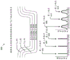
多个反应器(诸如,反应器5521、反应器5522、反应器5523和反应器5524)各自向网络产生(或以其他方式输送或提供)特定的碳添加剂/填料,所述网络被调谐以得到特定的限定频谱特征曲线。碳添加剂(诸如,第一调谐碳554、第二调谐碳556、第三调谐碳558和第四调谐碳560)可与其他(碳基或非碳基)组合物550混合。任何已知技术均可用于混合、加热、预处理、后处理或以其他方式组合特定碳添加剂与其他组合物。呈现混合器(诸如混合器5621、混合器5622、混合器5623和混合器5624)以展示不同调谐碳可如何引入到轮胎的各种部件中。用于轮胎组件的其他技术可涉及其他构造技术和/或包括轮胎的其他部件。可使用用于多帘布层轮胎的任何已知技术。此外,可基于特定主体帘布层和/或胎面层调配物的特性来确定特定主体帘布层和/或胎面层(诸如一组主体帘布层和/或胎面层568,包括主体帘布层和/或胎面层5681、主体帘布层和/或胎面层5682、主体帘布层和/或胎面层5683和主体帘布层和/或胎面层5684)的频谱特征曲线。例如,基于刺激和响应特性,第一主体帘布层和/或胎面层调配物(诸如主体帘布层和/或胎面层调配物5641)可展现出第一频谱特征曲线,而第二主体帘布层和/或胎面层调配物(诸如主体帘布层和/或胎面层调配物5642)可展现出第二频谱特征曲线。A plurality of reactors (such as reactor 552 1 , reactor 552 2 , reactor 552 3 , and reactor 552 4 ) each produce (or otherwise deliver or provide) a particular carbon additive/filler to a network that Tuned to obtain a specific defined spectral characteristic curve. Carbon additives such as
所得的不同调配物(诸如,主体帘布层和/或胎面层调配物5641、主体帘布层和/或胎面层调配物5642、主体帘布层和/或胎面层调配物5643和主体帘布层和/或胎面层调配物5644)用于形成为轮胎组件566的不同主体帘布层和/或胎面层中,所述主体帘布层和/或胎面层中的每一者展现出对应的频谱特征曲线。The resulting different formulations (such as, body ply and/or tread layer formulation 564 1 , body ply and/or tread layer formulation 564 2 , body ply and/or tread layer formulation 564 3 and The body ply and/or tread layer formulation 5644 ) is used in the different body ply and/or tread layers formed into the
图6示出从由含碳调谐谐振材料层形成的轮胎发射的第二组示例条件签名600。可在任何环境中发射示例条件签名600或其任何方面。图3F1示出新轮胎的多个主体帘布层和/或胎面层(诸如,主体帘布层和/或胎面层#1、主体帘布层和/或胎面层#2和主体帘布层和/或胎面层#3)。如该示例中以及在别处参考所呈现实现方式中的任何一者或多者所使用,术语“帘布层”可以是指轮胎的主体内的帘布层或层,或另选地,轮胎胎面的远离轮胎的主体径向向外突出以意欲用于与硬路面接触或对于越野轮胎与土地接触的层。在示例中,第一主体帘布层和/或胎面层是使用调谐碳进行调配(指用特定配方产生),使得第一主体帘布层和/或胎面层在使用1.0GHz声脉冲刺激(诸如第一声脉冲602)刺激时在1.0GHz下谐振。类似地,第二主体帘布层和/或胎面层是使用调谐碳进行调配,使得第二主体帘布层和/或胎面层在使用2.0GHz声脉冲刺激(诸如第二声脉冲604)刺激时在2.0GHz下谐振。另外,第三主体帘布层和/或胎面层是使用调谐碳进行调配,使得第三主体帘布层和/或胎面层在使用3.0GHz声脉冲刺激(诸如第三声脉冲606)刺激时在3.0GHz下谐振。如第一响应608、第二响应610和第三响应614所示,所有三个主体帘布层和/或胎面层在其相应调谐频率下作出响应。FIG. 6 shows a second set of
收发器天线可位于对应轮胎的轮窝中和/或上。处置任何此类所产生响应信号的系统可被配置为与源于其他表面(诸如车辆的其余非目标轮胎)的其他潜在响应区分开。例如,即使安装在车辆的右前车轮上的右前轮胎可能会对从位于车辆的左前轮窝中的收发器天线发射的声脉冲作出响应,但是与来自车辆的左前轮胎的响应信号相比,来自右前轮胎的响应信号将明显衰减(并因此被辨识出)。The transceiver antenna may be located in and/or on the wheel well of the corresponding tire. A system that handles any such generated response signals may be configured to distinguish it from other potential responses originating from other surfaces, such as the remaining non-target tires of the vehicle. For example, even though the right front tire mounted on the vehicle's front right wheel may respond to acoustic pulses emitted from a transceiver antenna located in the vehicle's left front wheel well, the response signal from the vehicle's left front tire is much less The response signal from the right front tire will be significantly attenuated (and thus recognized).
当收发器天线位于对应轮胎的轮窝中时,来自对应轮胎的响应将相对于声脉冲刺激而衰减。例如,来自对应轮胎的响应可相对于声脉冲刺激衰减9分贝(-9dB)或更多,或可相对于声脉冲刺激衰减18分贝(-18dB)或更多,或可相对于声脉冲刺激衰减36分贝(-36dB)或更多,或可相对于声脉冲刺激衰减72分贝(-72dB)或更多。在一些情况下,声脉冲信号产生器被设计为与位于轮窝中的收发器天线组合,以便使得对应轮胎的声脉冲响应衰减不超过75dB(-75dB)。When the transceiver antenna is located in the wheel well of the corresponding tire, the response from the corresponding tire will be attenuated relative to the acoustic pulse stimulus. For example, the response from the corresponding tire may be attenuated by 9 decibels (-9 dB) or more relative to the sonic pulse stimulus, or may be attenuated by 18 decibels (-18 dB) or more relative to the sonic pulse stimulus, or may be attenuated relative to the sonic pulse stimulus 36 decibels (-36dB) or more, or can attenuate 72 decibels (-72dB) or more relative to the acoustic pulse stimulus. In some cases, the acoustic impulse signal generator is designed in combination with the transceiver antenna located in the wheel well so as to attenuate the acoustic impulse response of the corresponding tire by no more than 75 dB (-75 dB).
图7描绘在一些含碳调谐谐振材料磨损之后从轮胎发射的第三组示例条件签名700。可选地,可在本文描述的实现方式的架构和功能的背景中实施示例条件签名700或其任何方面的一个或多个变体。可在任何环境中发射示例条件签名700或其任何方面。FIG. 7 depicts a third set of
在该示例中,轮胎已发生磨损。更明确地说,最外的主体帘布层和/或胎面层已完全磨掉。因此,1.0GHz下的声脉冲刺激将不产生来自最外帘布层的响应。此在图表中示出为第一响应衰减702。随着轮胎继续经历胎面磨损,来自下一个主体帘布层和/或胎面层的声脉冲响应和来自下一个连续主体帘布层和/或胎面层的声脉冲响应等将衰减,所述衰减可用于测量轮胎的总胎面磨损。另选地,可在所有帘布层中使用相同的调谐碳。可基于来自轮胎的返回信号签名来确定轮胎的胎面磨损以及其他指示。In this example, the tires are worn. More specifically, the outermost body plies and/or tread layers have been completely worn away. Therefore, acoustic pulse stimulation at 1.0 GHz will produce no response from the outermost ply. This is shown as
图8是两个层的俯视图,其中每一层容纳一个开口环谐振器(SRR),例如,形成包括两个同心SRR的示例开口环谐振器(SRR)配置。如本文所使用,开口环谐振器(SRR)由安置于介电基板上的一对同心环组成,其中每一环具有狭缝(例如,由于印刷图案)。当借助时变磁场激发SRR阵列时,所述结构表现为在SRR谐振点周围的窄频带中具有负有效磁导率的有效介质。许多几何形状是可能的,例如,使得包括尺寸“a”、“r”和/或“c”的每一SRR之间的尺寸和/或间距被选择为实现特定的对应频谱响应。例如,“a”可约为1mm,“r”可为2mm,并且“c”可约为0.6mm。这些尺寸可对应于产生期望和/或预期的频谱响应,例如,导致相对较宽和/或较广的信号响应而非窄和/或陷波响应,从而便于改善频谱分析,导致在使用频谱分析工具(诸如频谱分析仪)时提高成本效率。另外地或另选地,相较于越野应用等,所述尺寸中的任一者可被进一步调整以实现特定的期望最终结果目标,例如赛道中的应用。一个特定几何形状涉及同心环之间的间隙。此类间隙产生电容,所述电容结合该对同心环中固有的电感会引入集合的谐振的变化。FIG. 8 is a top view of two layers, where each layer houses a split ring resonator (SRR), eg, forming an example split ring resonator (SRR) configuration including two concentric SRRs. As used herein, a split ring resonator (SRR) consists of a pair of concentric rings disposed on a dielectric substrate, where each ring has a slit (eg, due to a printed pattern). When the SRR array is excited with a time-varying magnetic field, the structure behaves as an effective medium with negative effective permeability in a narrow frequency band around the SRR resonance point. Many geometries are possible, eg, such that the dimensions and/or spacing between each SRR, including dimensions "a", "r" and/or "c", are selected to achieve a particular corresponding spectral response. For example, "a" may be approximately 1 mm, "r" may be 2 mm, and "c" may be approximately 0.6 mm. These dimensions may correspond to producing a desired and/or anticipated spectral response, for example, resulting in a relatively broad and/or broad signal response rather than a narrow and/or notched response, thereby facilitating improved spectral analysis, resulting in Improve cost efficiency when using tools such as spectrum analyzers. Additionally or alternatively, any of the dimensions may be further tuned to achieve a particular desired end-result goal, such as in race track applications, as compared to off-road applications and the like. One particular geometry involves gaps between concentric rings. Such gaps create capacitances that, in combination with the inductance inherent in the pair of concentric rings, introduce variations in the resonance of the ensemble.
可印刷、薄片定向、圆柱类型、开口环谐振器设计可由任何导电材料建构,包括金属、导电非金属、介电材料、半导体材料等。除了基于导电材料的选择和/或处理进行调谐之外,还可以通过改变几何形状使得相应地调整有效电容率来调谐开口环谐振器。随着开口环谐振器的形状而变的有效电容率在方程1中给出。Printable, sheet-oriented, cylinder-type, split-ring resonator designs can be constructed from any conductive material, including metals, conductive non-metals, dielectric materials, semiconductor materials, and more. In addition to tuning based on the choice and/or processing of the conductive material, split ring resonators can also be tuned by changing the geometry such that the effective permittivity is adjusted accordingly. The effective permittivity as a function of the shape of the split-ring resonator is given in

其中a是圆柱的间距,ω是角频率,μ0是自由空间的磁导率,r是半径,d是同心导电薄片的间距,l是堆叠长度,c是环厚度,并且σ是围绕圆周测量的薄片的单位长度的电阻。where a is the spacing of the cylinders, ω is the angular frequency, μ0 is the magnetic permeability of free space, r is the radius, d is the spacing of the concentric conductive sheets, l is the stack length, c is the ring thickness, and σ is measured around the circumference The resistance per unit length of the sheet.
在一些情况下,可使a的值(例如,圆柱形开口环谐振器的圆柱的间距)变得相对较小,使得同心环吸收相对较窄的频率范围内的EM辐射。在其他情形下,可使a的值变得相对较大,使得同心环各自吸收间隔开大区间的频率下的EM辐射。在一些情况下,不同尺寸的SRR可安置在轮胎的不同表面上。在一些情况下,安置在轮胎的不同表面上的不同尺寸的SRR可用于测量轮胎条件(例如,温度、老化、磨损等)。In some cases, the value of a (eg, the pitch of the cylinders of a cylindrical split ring resonator) can be made relatively small so that the concentric rings absorb EM radiation over a relatively narrow frequency range. In other cases, the value of a can be made relatively large so that the concentric rings each absorb EM radiation at frequencies separated by a large interval. In some cases, different sized SRRs may be placed on different surfaces of the tire. In some cases, different sized SRRs placed on different surfaces of the tire may be used to measure tire condition (eg, temperature, age, wear, etc.).
在一些实施方案中,形成开口环谐振器的材料是复合材料。每一SRR可被配置为对EM刺激作出任何特定的期望调谐响应。至少由于SRR被设计为模拟原子的谐振响应(尽管尺度大得多并且频率较低),比原子尺度大的SRR允许更大程度地控制谐振响应。此外,SRR比自然界中发现的铁磁性材料反应性高得多。SRR的明显磁性响应伴随着优于较重、天然存在的材料的显著优点。In some embodiments, the material forming the split ring resonator is a composite material. Each SRR can be configured to have any particular desired tuned response to EM stimuli. SRRs larger than the atomic scale allow for a greater degree of control over the resonant response, at least because SRRs are designed to mimic the resonant response of atoms (albeit on a much larger scale and at lower frequencies). Furthermore, SRRs are much more reactive than ferromagnetic materials found in nature. The pronounced magnetic response of SRRs is accompanied by significant advantages over heavier, naturally occurring materials.
图9示出展示用于通过基于阻抗的光谱法进行轮胎磨损感测的完整轮胎诊断系统和设备的示意图。轮胎900,诸如填充有空气或氮气(N2)的气动橡胶轮胎,可包括传统的轮胎部件,包括主体920、内衬层912、胎圈填料区域922、胎圈916、一个或多个带束层904、906、908和910、胎面902和基于阻抗的光谱磨损感测印刷电子器件918(另选地,包括碳基微观结构的传感器,所述碳基微观结构用于通过嵌入于带束层904–910中的任何一者或多者内的谐振器进行信号频移和衰减监测)。Figure 9 shows a schematic diagram showing a complete tire diagnostic system and apparatus for tire wear sensing by impedance-based spectroscopy.
如此处所示,无线应变传感器可放置在内衬层的表面上或侧面上(或嵌入于其中)以监测轮胎条件,确保汽车安全(诸如检测受损轮胎)。轮胎变形或应变监测可(间接地)提供表示轮胎与接触路面之间的摩擦程度的信息,所述信息随后可用于优化汽车轮胎控制系统。所述轮胎信息可基于谐振传感器平台无线地传输到位于轮胎轮毂中的接收器。As shown here, wireless strain sensors can be placed on the surface or sides of the innerliner (or embedded in it) to monitor tire conditions for vehicle safety (such as detecting damaged tires). Tire deformation or strain monitoring can (indirectly) provide information indicative of the degree of friction between the tire and the contacting road surface, which can then be used to optimize the car's tire control system. The tire information may be wirelessly transmitted to a receiver located in the hub of the tire based on the resonant sensor platform.
图10示出用于提供经由遥测传送到导航系统或用于制造印刷碳基材料的设备中的轮胎磨损相关信息的系统1000。系统1000可与目前公开的系统、方法和材料中的任何一者或多者(诸如包括碳基微观结构的传感器)一起起作用,使得省去对其的重复描述。阻抗光谱法,也被称为电化学阻抗光谱法(EIS),是指在测量样本(诸如结合到轮胎1002的一个或多个轮胎带束层内的包含碳基微观结构的传感器)时涉及在广泛范围的频率内施加正弦电化学扰动(电位或电流)的阻抗转导方法。印刷碳基谐振器1004可结合在一个或多个轮胎部件(诸如轮胎带束层)内,其中印刷碳基谐振器1004中的每一者具有所示的大体椭圆形构造,或者适于实现适合于通过监测频移和/或衰减来有效且精确地检测车辆部件磨损(诸如第一响应衰减指示具有约1.0GHz的固有谐振频率的轮胎主体帘布层和/或胎面层的磨损)的特定期望谐振性质的某其他形状或构造。Figure 10 shows a
能够形成印刷碳基谐振器1004的辊1010的组件包括碳基微观结构和/或微观结构材料(诸如石墨烯)的存储库1012(诸如槽)、网纹辊1014(指通常由钢或铝芯构成的硬滚筒,所述钢或铝芯由表面含有数百万个极精细凹坑(被称为单元)的工业陶瓷涂布)、印版滚筒1016和压印滚筒1018。在操作中,从存储库1012提取的石墨烯可通过辊1010的组件中的辊来辊压、压制、拉伸或以其他方式制造成印刷碳基谐振器1004。对于系统1000的运行,可能不需要印刷碳基谐振器1004的对齐(指对准)。Components of the
因此,前述特征的任何组合可用于制造轮胎,所述轮胎具有谐振器(指实际或“等效”槽、LC和/或谐振电路),其中含碳微观结构自身可响应于来自收发器的所发射RF信号和/或由先进能源供应的能量而谐振,使得安置到任何一个或多个部件(诸如轮胎的胎面、一个或多个帘布层、内衬层等)中或上的其他传感器可展现出频移或信号衰减性质或行为。所描述的谐振器不一定需要体现为实际电和/或集成电路(IC)。所描述的谐振器可简单地实现为调谐含碳微观结构,因此避免当在可分解材料(诸如轮胎胎面层)中实施传统离散电路时可能出现的常见劣化问题。此类谐振器可响应于外部供应的‘声脉冲’(诸如由位于车辆的轮窝中的收发器供应)而谐振,或谐振器可对通过使用任何变化或任何数目的电力或电荷产生器(诸如热电产生器、压电能量产生器、摩擦电能量产生器等)促进的共置(指在同一轮胎胎面层内,但可能在该轮胎胎面层内的不同位置处)、自供电、自探查能力来充电而作出响应。Thus, any combination of the aforementioned features can be used to make tires having resonators (referring to actual or "equivalent" grooves, LCs, and/or resonant circuits) in which the carbonaceous microstructure itself can respond to all signals from the transceiver. Transmitting RF signals and/or resonating with energy supplied by an advanced energy source such that other sensors disposed in or on any one or more components (such as the tread, one or more plies, innerliner, etc. of a tire) can Exhibits frequency shifting or signal attenuation properties or behavior. The described resonators do not necessarily need to embody actual electronics and/or integrated circuits (ICs). The described resonators can be implemented simply as tuned carbonaceous microstructures, thus avoiding common degradation problems that can arise when implementing traditional discrete circuits in decomposable materials such as tire tread layers. Such resonators may resonate in response to externally supplied 'acoustic pulses', such as supplied by transceivers located in the wheel wells of the vehicle, or the resonators may be resonant by using any variation or number of power or charge generators ( co-located (meaning within the same tire tread layer, but possibly at different locations within that tire tread layer), self-powered, Self-probe capability to charge and respond.
在轮胎滚动或以其他方式发生变形的任何时候,所描述谐振器(和其他谐振器和/或谐振电路)中的任一者可被配置为发射和/或进一步发射振荡RF信号(或其他形式的电磁辐射,视总体配置而定)。随着车辆轮胎经历由于使用(诸如在道路上行驶或越野行驶)导致的磨损,与路面或地面(土地)接触的轮胎胎面层可即刻或随时间推移经历变形(诸如从“压扁”观察到,压扁是指在旋转或滚动期间露出的车辆轮胎胎面层区段的至少部分变扁,和/或从转弯期间所经历的侧向运动等观察到),因此所得信号频移和/或衰减行为可依照此类“压扁”发生改变,因为相关联信号可在一个或多个已知振幅范围内振荡。另外地或另选地,随着轮胎经历变形,所观察的信号可在对应于特定谐振器的已知频率范围内振荡,从而允许精确地且准确地识别在发生振荡时发生的劣化的类型,而不是需要驾驶员、乘客和/或其他车辆乘员在车辆静止时离开车辆来观察轮胎胎面条件。此类频移振荡可作为所述已知频率范围内的两个或更多个频率之间的来回频移而观察到。Any of the described resonators (and other resonators and/or resonant circuits) may be configured to transmit and/or further transmit an oscillating RF signal (or other form of electromagnetic emissions, depending on the overall configuration). As vehicle tires experience wear from use (such as on-road or off-road driving), the tire tread layers that come into contact with the road or ground (earth) may undergo deformation, either immediately or over time, such as from "flattening" recognized that flattening refers to the at least partial flattening of a segment of the tread layer of a vehicle tire exposed during rotation or rolling, and/or as observed from lateral motion experienced during cornering, etc.), the resulting signal frequency shifts and/or Or the attenuation behavior can change according to such "squeezing" because the associated signal can oscillate within one or more known amplitude ranges. Additionally or alternatively, as the tire undergoes deformation, the observed signal may oscillate within a known frequency range corresponding to a particular resonator, allowing precise and accurate identification of the type of degradation that occurs when the oscillation occurs, Rather than requiring the driver, passengers and/or other vehicle occupants to leave the vehicle while the vehicle is stationary to observe tire tread conditions. Such frequency-shifted oscillations may be observed as a back-and-forth frequency shift between two or more frequencies within the known frequency range.
位于内衬层的侧面上的有无线能力的应变(诸如表示由外部约束或负载引起的材料主体中的粒子之间的相对位移的变形的几何度量)传感器可监测轮胎条件,以确保汽车安全(诸如通过检测受损轮胎)。另外,轮胎变形或应变监测可间接地提供与轮胎与道路表面之间的摩擦程度有关的信息,所述信息随后可用于优化汽车轮胎控制系统。此类轮胎信息可基于谐振传感器(诸如阻抗光谱法IS传感器)平台无线地传输到位于车轮轮毂中的接收器(和/或收发器)。Wirelessly capable strain (such as a geometric measure of deformation representing relative displacement between particles in a body of material caused by external constraints or loads) sensors located on the side of the innerliner can monitor tire conditions to ensure automotive safety ( such as by detecting damaged tires). In addition, tire deformation or strain monitoring can indirectly provide information on the degree of friction between the tire and the road surface, which can then be used to optimize automotive tire control systems. Such tire information may be wirelessly transmitted to a receiver (and/or transceiver) located in the hub of the wheel based on a resonant sensor (such as an impedance spectroscopy IS sensor) platform.
图11是与用于通过帘布层印刷编码确定车辆轮胎磨损的基于谐振序列号的数字编码系统有关的示意图1100。所述基于谐振序列号的数字编码系统可与目前公开的系统、方法和传感器中的任一者结合和/或一起起作用。基于谐振序列号的数字编码系统通过帘布层印刷编码提供对轮胎的数字编码,因此提供对轮胎的摇篮到坟墓(指完整的使用寿命)追踪(和相关性能度量)和使用特征曲线,而不需要对轮胎中的常规磨损和撕裂敏感的传统电子装置。11 is a schematic diagram 1100 relating to a resonant serial number based digital encoding system for determining vehicle tire wear via ply printed encoding. The resonant serial number based digital encoding system may be combined and/or function with any of the presently disclosed systems, methods and sensors. A digital encoding system based on a resonant serial number provides digital encoding of tires via ply-printed encoding, thus providing cradle-to-grave (referring to complete service life) tracking (and associated performance metrics) of the tire and usage profile without the need for Legacy electronics sensitive to normal wear and tear in tires.
在一些实现方式中,通过轮胎胎面层印刷对轮胎的谐振序列号数字编码可促进对轮胎的摇篮到坟墓轮胎追踪和使用,而不一定需要轮胎内存在电子装置。例如,连同通过阻抗光谱法完成的轮胎磨损感测,额外谐振器可数字地编码到例如用于遥测追踪的序列号的一个或多个印刷图案上。因此,如此装备的车辆可在不需要射频识别(RFID)技术的情况下追踪胎面磨损、行驶英里数(例如,总计)和轮胎年龄。In some implementations, digitally encoding a tire's resonant serial number through tire tread layer printing can facilitate cradle-to-grave tire tracking and use of the tire without necessarily requiring the presence of electronics within the tire. For example, along with tire wear sensing accomplished by impedance spectroscopy, additional resonators may be digitally encoded onto one or more printed patterns such as a serial number for telemetry tracking. Accordingly, a vehicle so equipped can track tread wear, miles driven (eg, total), and tire age without the need for radio frequency identification (RFID) technology.
连同通过阻抗光谱法(IS)和/或电化学阻抗光谱法(EIS)进行轮胎磨损感测,额外谐振器可数字地编码到印刷图案上以提供用于基于遥测的轮胎性能追踪的可辨识序列号。通过逐渐地印刷到主体帘布层和/或胎面层上,结合了所讨论的印刷碳基谐振器的轮胎可天生是序列化的。Along with tire wear sensing via Impedance Spectroscopy (IS) and/or Electrochemical Impedance Spectroscopy (EIS), additional resonators can be digitally encoded onto the printed pattern to provide a recognizable sequence for telemetry-based tire performance tracking Number. Tires incorporating the discussed printed carbon-based resonators may be inherently serializable by printing progressively onto the body ply and/or tread layer.
图12示出用于轮胎中的谐振序列号编码的示意图1200。序列号“6E”如图所示编码在印刷碳谐振器的特殊准备的阵列中,所述谐振器被配置为根据‘声脉冲’刺激-响应图1212谐振,从而允许方便且可靠地识别如此装备的车辆轮胎的该特定主体帘布层和/或胎面层。Figure 12 shows a schematic 1200 for resonant serial number encoding in a tire. Serial number "6E" as shown is encoded in a specially prepared array of printed carbon resonators configured to resonate according to the 'acoustic pulse' stimulus-
图13被呈现来说明开口环谐振器(SRR)用作谐振装置,所述谐振装置促成由不同的近端存在谐振器类型产生的集合现象。该图示出了轮胎的内表面1301,其中所述内表面具有两个开口环谐振器(例如,开口环谐振器1303A和开口环谐振器1303B),所述开口环谐振器中的每一者形成电路配置1902,所述电路配置可被调谐以使信号在特定频率下衰减和/或在特定频率范围内衰减。在该实施方案中,电路配置1902被示出为对应于基本上圆形的开口环谐振器的几何图案;然而,另选的电路配置可具有不同的几何图案(例如,圆柱形、椭圆形、矩形、卵形、正方形等),因此,任何可设想到的几何配置是可能的。可基于对几何图案的谐振能力的影响来选择几何配置的变体。明确地说且如图所示,几何图案可包括具有各种聚结图案(例如,聚结图案1306、聚结图案1308和聚结图案1310)的自组装的碳基粒子,所述碳基粒子中的任何一者或多者可构成可能会影响其中结合了碳基微观结构的材料的谐振性能的集中区域1304。一个聚结图案和/或一系列聚结图案也可能会影响其中结合了碳基微观结构的材料的谐振性能。Figure 13 is presented to illustrate the use of a split ring resonator (SRR) as a resonant device that facilitates the aggregation phenomenon produced by the different proximal presence resonator types. This figure shows the
在各种配置中,碳基微观结构至少部分由石墨烯形成。在此上下文中,石墨烯是指在一个原子形成各顶点的二维六角晶格中呈原子单层形式的碳的同素异形体。多个此类六角晶格的共同定位和/或并置成更复杂的结构会引入其他谐振效应。例如,两个石墨烯薄片或小片的并置1302可在它们之间在一频率下谐振,所述频率取决于薄片和/或小片的长度、宽度、间距、厚度、间距形状和/或其他物理特性和/或其彼此的相对并置。In various configurations, the carbon-based microstructure is formed at least in part from graphene. In this context, graphene refers to an allotrope of carbon in the form of an atomic monolayer in a two-dimensional hexagonal lattice in which one atom forms each vertex. Co-location and/or juxtaposition of multiple such hexagonal lattices into more complex structures introduces additional resonance effects. For example, the
表1描绘了起因于集合效应的一系列可能衰减。如表中所示,所述结构中的每一者具有对应于其尺度标记的不同谐振频域。Table 1 depicts a range of possible attenuations due to aggregation effects. As shown in the table, each of the structures has a different resonant frequency domain corresponding to its scale label.

表1:集合效应示例Table 1: Example of Aggregate Effects
任何数目的不同开口环谐振器可印刷到轮胎的表面上。此外,任何数目的不同尺寸的开口环谐振器可印刷到轮胎的任何表面上。对特定开口环谐振器的材料和/或大小和/或其他结构或尺寸特性的选择可用于控制该特定谐振器开口环的谐振频率。可印刷一系列尺寸不同的开口环谐振器,使得所述图案对应于数字编码值。经由电磁信号通信刺激一系列尺寸不同的开口环谐振器(例如扫掠通过8GHz至9GHz或类似范围)并且通过返回范围测量衰减响应产生可辨识的编码序列号。许多不同的编码方案是可能的,因此,表2的非限制性示例仅用于说明。Any number of different split ring resonators can be printed onto the surface of the tire. Furthermore, any number of different sized split ring resonators can be printed onto any surface of the tire. Selection of the material and/or size and/or other structural or dimensional characteristics of a particular split ring resonator may be used to control the resonant frequency of the split ring of that particular resonator. A series of split ring resonators of different sizes can be printed such that the pattern corresponds to a digitally encoded value. Stimulating a series of split ring resonators of different sizes via electromagnetic signal communication (eg sweeping through 8GHz to 9GHz or similar range) and measuring the decay response through the return range yields a identifiable coded sequence number. Many different encoding schemes are possible, therefore, the non-limiting examples of Table 2 are for illustration only.

表2:示例编码方案Table 2: Example Encoding Schemes
图14示出根据一些实现方式的轮胎传感器1400的示意图。在一个实现方式中,轮胎传感器1400可包括具有多个轮胎帘布层的轮胎主体的区段1402(例如,如图9所示)。轮胎传感器1400可检测轮胎帘布层1408的温度,例如,轮胎传感器1400结合到所述轮胎帘布层中。在一个实现方式中,轮胎传感器可包括陶瓷材料1404(例如,组织为矩阵)和一个或多个SRR 1406,诸如图8和本公开别处所示。一个或多个SRR 1406中的每一者可具有可响应于相应轮胎的弹性体性质变化或温度变化中的一者或多者而偏移的固有谐振频率(例如,如图16中所示)。导电层1410可与一个或多个SRR 1406中的相应SRR介电分离。在一些实现方式中,轮胎传感器1400可被生产并在没有结合到轮胎中的情况下运送,使得可在之后结合到轮胎和/或轮胎帘布层内。FIG. 14 shows a schematic diagram of a
另外地或另选地,轮胎传感器1400可结合到被配置为检测车辆中的轮胎应变(例如,如图16所示)的系统(图14中未示出)中。所述系统可包括安置在车辆或车辆部件中的一者或多者上的天线(例如,如在本公开中关于电磁信号的发射和/或传播所讨论)。所述天线被配置为输出电磁声脉冲。所述系统还可以包括轮胎,所述轮胎包括由一个或多个轮胎帘布层形成的主体(例如,如图9所示)。轮胎帘布层中的任何一者或多者可包括开口环谐振器(SRR),例如,如本公开中所讨论。在一个实现方式中,每一SRR具有被配置为响应于相应的一个或多个轮胎帘布层的弹性体性质(例如,可逆变形、应力和/或应变)的变化而成比例地偏移(例如,如图16中所示)的固有谐振频率。Additionally or alternatively,
在一些实现方式中,所描述系统可用于检测与轮胎和/或车辆(例如汽车和卡车)相关的配置外部的材料的物理性质的变化。例如,所述系统可检测飞机机翼和/或其他类型的气翼(例如与航天器和/或其类似者相关联)的表面温度的变化。此外,所述系统可准许一个或多个SRR 1406在医院环境中可用可移除方式粘附到患者身上的情况,使得可在不使用常规热传感器的情况下获得相应患者的体温读数(例如,依赖于辐射传热技术等)。在这些示例中的任一者以及其他示例中,此类系统可检测与表面相关联的物理性质。In some implementations, the described systems can be used to detect changes in physical properties of materials associated with tires and/or vehicles (eg, cars and trucks) outside of the configuration. For example, the system may detect changes in surface temperature of aircraft wings and/or other types of airfoils (eg, associated with spacecraft and/or the like). Additionally, the system may permit one or more SRRs 1406 to be removably adhered to a patient in a hospital setting such that temperature readings of the corresponding patient may be obtained without the use of conventional thermal sensors (e.g., rely on radiative heat transfer techniques, etc.). In any of these examples, as well as other examples, such systems can detect physical properties associated with a surface.
在一个实现方式中,所述系统可包括被配置为输出电磁声脉冲的单个天线和一个或多个柔性基板。柔性基板中的每一者可包括第一侧,所述第一侧包括安置在柔性基板上的多个开口环谐振器(SRR)(例如,一个或多个SRR 1406)。每一SRR可具有可响应于相应的一个或多个轮胎帘布层的弹性体性质变化而成比例地偏移(例如,如图16中所示)的固有谐振频率。所述弹性体性质可包括可逆变形、应力、应变或温度中的一者或多者。这样,所述系统可产生吸收特征曲线(例如,指由天线输出的电磁声脉冲的吸收现象的独特变化)。所述系统可包括与第一侧相对定位的第二侧。所述第二侧可附接到所述表面。单个天线可分析与吸收特征曲线相关联的数据并输出物理性质的构形。In one implementation, the system may include a single antenna and one or more flexible substrates configured to output electromagnetic acoustic pulses. Each of the flexible substrates may include a first side including a plurality of split ring resonators (SRRs) (eg, one or more SRRs 1406 ) disposed on the flexible substrate. Each SRR may have a natural resonant frequency that may shift proportionally (eg, as shown in FIG. 16 ) in response to changes in the elastomeric properties of the corresponding one or more tire plies. The elastomeric properties may include one or more of reversible deformation, stress, strain or temperature. In this way, the system can generate an absorption profile (eg, referring to a unique variation in the absorption phenomenon of an electromagnetic acoustic pulse output by an antenna). The system may include a second side positioned opposite the first side. The second side is attachable to the surface. A single antenna can analyze data associated with an absorption profile and output a configuration of physical properties.
图15描绘根据一些实现方式的测量谐振签名信号强度(以分贝dB为单位)相对于轮胎胎面层损失的高度(以毫米mm为单位)的曲线图1500。如此处所示,含碳微观结构和/或微观结构材料可结合到传感器中,或者在一些配置中,以给定浓度水平或多个不同浓度水平(在一个或多个轮胎胎面层中的每一者中)结合到一个或多个轮胎胎面的全部层中以实现所示的独特劣化特征曲线。也就是说,测量谐振签名(指所讨论的特定轮胎胎面层的识别“签名”)可如本文中所描述由一个或多个RF信号“探查”以展现如所示的该发射信号的衰减。15 depicts a
新的轮胎胎面层可被配置为指示约为0的信号强度(以分贝dB为单位测量)。该强度可与该轮胎胎面层的劣化程度成比例地改变。例如,轮胎胎面层(假定与路面接触的轮胎胎面层)的2mm高度损失可与所示的测量谐振签名信号强度特征曲线相对应。6.7GHz下的‘声脉冲’信号可在约9dB的强度等级下测量,依此类推。A new tire tread layer may be configured to indicate a signal strength (measured in decibels dB) of about 0. The strength may vary in proportion to the degree of degradation of the tire tread layer. For example, a 2 mm height loss of a tire tread layer (assumed to be in contact with the road surface) may correspond to the measured resonance signature signal strength profile as shown. A 'burst' signal at 6.7GHz can be measured at a strength level of about 9dB, and so on.
因此,独特的浓度水平、化学性质、分散、分布和/或其类似者的含碳微观结构可嵌入轮胎胎面层中(或在一些情况下,置放于轮胎胎面层的一个或多个表面上)以实现如所示的独特且可易于识别的测量谐振签名信号强度。因此,在行驶期间发生轮胎胎面磨损时,可立即告知此类系统的用户所述轮胎胎面磨损的确切程度和位置,而不是局限于在车辆处于静止状态下观察轮胎,这个过程可能既费时又繁琐。Thus, carbonaceous microstructures of unique concentration levels, chemistries, dispersions, distributions, and/or the like may be embedded in (or in some cases, placed on one or more of the tire tread layers) ostensibly) to achieve a unique and easily identifiable measured resonance signature signal strength as shown. As a result, users of such systems are immediately informed of the exact extent and location of tire tread wear when it occurs while driving, rather than being limited to viewing the tires while the vehicle is stationary, which can be time consuming And cumbersome.
图16描绘根据一些实现方式的测量谐振签名信号强度(以分贝dB为单位)相对于结合到轮胎胎面和/或轮胎帘布层(例如,如本公开中所讨论)中的开口环谐振器(SRR)的固有谐振频率的曲线图1600。如此处所示,含碳和/或碳质微观结构和/或微观结构材料可结合到传感器中,或者在一些配置中,以给定浓度水平或多个不同浓度水平(在一个或多个轮胎胎面层中的每一者中)结合到一个或多个轮胎胎面的全部层中以实现所示的独特劣化特征曲线。也就是说,测量谐振签名(指所讨论的特定轮胎胎面层的识别“签名”)可如本文中所描述由一个或多个RF信号“探查”以展现如所示的该发射信号的偏移,例如代表性的和/或与可逆轮胎变形(例如,应力和/或应变)(如可在漂移情境中遇到)的程度成比例。这样,可依据轮胎变形,例如应变(与漂移相关联),对SRR“响应”信号行为建模,从而在与图13的曲线图(所述曲线图可指示在常规向前滚动操作中遇到的轮胎磨损等)一起考虑时得到轮胎条件和性能的完整图像。16 depicts measured resonance signature signal strength (in decibels in dB) relative to a split ring resonator incorporated into a tire tread and/or tire ply (eg, as discussed in this disclosure), according to some implementations (
产生侧向轮胎静摩擦损失的真实世界情境可包括漂移和/或打滑,例如意指当在车辆的车轮与路面之间形成水层时发生的现象,从而导致失去防止车辆对控制输入作出响应的牵引力。如果所有的接触车轮同时发生打滑,则车辆实际上变成不可控的滑板。使用目前公开的SRR和/或谐振器结合天线和/或信号处理设备可例如通过使用与轮胎的表面联接的振动检测单元而有效地消除依赖于常规打滑检测技术的需要,所述轮胎可能会因为长时间的使用而劣化且受损。另外,图16示出与在漂移时在静摩擦损失期间遇到的侧向轮胎移动相关联的频谱响应(以信号分贝为单位)。在真实世界情境中,诸如暂时静摩擦损失可能会通过高音“尖叫”而被听到,与仅在快速向前旋转期间听到的其他声音不同。这类定期静摩擦损失(在漂移车辆恢复静摩擦和/或牵引力之前)可呈现(图16中未示出)为对应SRR的固有谐振频率的定期和/或周期性偏移。返回参看图16,可通过曲线的各种谷值和/或峰值的频率的微小的定期和/或周期性偏移而在视觉上描绘“尖叫”类型情形。Real-world scenarios that produce lateral tire stiction losses can include drifting and/or skidding, for example meaning phenomena that occur when a layer of water forms between the vehicle's wheels and the road surface, resulting in a loss of traction that prevents the vehicle from responding to control inputs . If all contacting wheels slip simultaneously, the vehicle effectively becomes an uncontrollable skateboard. Use of the presently disclosed SRRs and/or resonators in conjunction with antennas and/or signal processing devices can effectively eliminate the need to rely on conventional slip detection techniques, such as by using a vibration detection unit coupled to the surface of a tire that may be damaged due to Deteriorated and damaged by prolonged use. Additionally, Figure 16 shows the spectral response (in decibels of signal) associated with lateral tire movement encountered during a loss of stiction while drifting. In a real world situation, something like a temporary loss of stiction might be heard as a high-pitched "squeal", unlike other sounds that are only heard during rapid forward rotation. Such periodic stiction losses (before the drifting vehicle regains stiction and/or traction) may manifest (not shown in FIG. 16 ) as a regular and/or periodic shift in the natural resonant frequency of the corresponding SRR. Referring back to FIG. 16, a "screaming" type situation may be visually depicted by small regular and/or periodic shifts in the frequency of the various valleys and/or peaks of the curve.
如可看出,实时多模态谐振器支持用于使用用于弹性体性质变化检测的含谐振材料的传感器测量静摩擦的方法。在一个设置中,用于弹性体性质变化检测的一个或多个含谐振材料的传感器安置在换能器附近的位置。发射刺激信号以便激发用于弹性体性质变化检测的一个或多个含谐振材料的传感器。所述发射包括横跨已知频率范围的电磁能。校准信号是在已知静摩擦条件下捕获。在接收到至少部分地包括对刺激信号作出响应的频率的返回信号之后,将各种信号处理技术应用于所述返回信号。例如,对返回信号应用各种信号处理技术以与刺激信号进行比较。每当返回信号的频率和/或振幅不同于校准信号时,计算对应的界面间接电容率(例如,在轮胎与行驶表面之间的界面处)。将界面间接电容率的绝对值和/或相对值与静摩擦值相关(例如,使用校准表)。静摩擦值随时间推移的变化转而与道路和/或轮胎条件相关。As can be seen, real-time multi-modal resonators support methods for measuring stiction using resonant material-containing sensors for elastomer property change detection. In one arrangement, one or more sensors comprising a resonant material for detection of changes in the properties of the elastomer are positioned near the transducer. A stimulus signal is emitted to excite one or more resonant material-containing sensors for detection of changes in the properties of the elastomer. The emissions include electromagnetic energy spanning a known frequency range. Calibration signals are captured under known stiction conditions. After receiving a return signal comprising at least in part frequencies responsive to the stimulus signal, various signal processing techniques are applied to the return signal. For example, various signal processing techniques are applied to the return signal for comparison with the stimulus signal. Whenever the frequency and/or amplitude of the return signal differs from the calibration signal, a corresponding interfacial indirect permittivity (eg, at the interface between the tire and the running surface) is calculated. Correlate absolute and/or relative values of interfacial indirect permittivity to stiction values (eg, using a calibration table). Changes in static friction values over time are in turn related to road and/or tire conditions.
构成前述校准信号和/或校准表的静态和/或动态值可至少部分地基于对刺激信号的分析和/或对换能器附近的环境的分析。此外,前述校准信号和/或校准表可涵盖电容率校准信号、磁导率校准信号、温度校准信号、振动校准信号、掺杂校准信号等。在一个实现方式中,校准程序可在已知和/或受控环境条件(例如,干燥路面和晴朗的天气)下执行,以在各种面向前的角速度下产生基线数据(使得测试车辆仅直接向前移动而无侧滑和/或滑动移动)。此基线数据接着充当一个或多个校准曲线,可随后根据所述一个或多个校准曲线比较和/或计算变形值。这样,可观测到相对于初始未拉伸(基线)校准曲线(例如,如图16中所示)的明显性能变化。The static and/or dynamic values making up the aforementioned calibration signal and/or calibration table may be based at least in part on an analysis of the stimulus signal and/or an analysis of the environment in the vicinity of the transducer. Furthermore, the aforementioned calibration signals and/or calibration tables may cover permittivity calibration signals, magnetic permeability calibration signals, temperature calibration signals, vibration calibration signals, doping calibration signals, and the like. In one implementation, a calibration procedure may be performed under known and/or controlled environmental conditions (e.g., dry pavement and clear weather) to generate baseline data at various forward-facing angular velocities (such that the test vehicle is only directly forward movement without side-slip and/or sliding movement). This baseline data then serves as one or more calibration curves from which deformation values can then be compared and/or calculated. In this way, a significant change in performance relative to the initial unstretched (baseline) calibration curve (eg, as shown in Figure 16) can be observed.
每当返回信号不同于校准信号时,返回信号相对于刺激信号的进一步分析可用于识别返回信号的哪些频率不同于校准信号。所述差异可作为一个或多个频率相对于校准信号的衰减而被观测和/或测量到。另外地或另选地,所述差异可作为峰值相对于校准信号的峰值的频移(如图16中所示,相对于对应地拉伸0.5%的数据等)而被观测/测量到。Whenever the return signal differs from the calibration signal, further analysis of the return signal relative to the stimulus signal can be used to identify which frequencies of the return signal differ from the calibration signal. The difference may be observed and/or measured as an attenuation of one or more frequencies relative to the calibration signal. Additionally or alternatively, the difference may be observed/measured as a frequency shift of the peak relative to the peak of the calibration signal (as shown in Figure 16, relative to correspondingly stretching the data by 0.5%, etc.).
图17示出被配置为以对应于编码序列号的方式谐振的开口环谐振结构的使用。开口环谐振结构的此类图案可印刷在轮胎或其他弹性体上。如图所示,通过四个不同大小的开口环谐振器的存在来示出编码序列号“E1”。刺激-响应图1700示出在约8GHz至约9GHz范围内的EM刺激,而响应被示出为在约-8dB至约-18dB范围内的衰减。经由跨越该范围的电磁信号通信刺激一系列不同大小的开口环谐振器并且测量跨越该范围的返回的S参数产生该特定印刷图案的方便且可靠的识别。随后,如果将独特图案印刷到一系列轮胎中的每一者上,并且如果图案与编码序列号相关联,则可基于图案对EM询问的响应来确定特定轮胎。Figure 17 illustrates the use of a split ring resonant structure configured to resonate in a manner corresponding to an encoded serial number. Such patterns of split ring resonant structures can be printed on tires or other elastomers. As shown, the coded serial number "E1" is shown by the presence of four differently sized split ring resonators. Stimulus-
更明确地说,如果独特图案被印刷到一系列轮胎中的每一者上,并且如果所述图案与编码序列号相关联,则可响应于对与编码方案对应的范围内的EM刺激的EM询问而基于所测量S参数(例如,对应于衰减的S参数比率)确定特定轮胎。在图17的示例中,衰减属于约-8dB至约-18dB的范围内,然而,在其他测量中,衰减属于约-1dB至约-9dB的范围内。在其他测量中,衰减属于约-10dB至约-19dB的范围内。在其他测量中,衰减属于约-20dB至约-35dB的范围内。在经验实验中,衰减基本上与在近端共同定位在轮胎表面上的不同配置的谐振器的数目无关。更明确地说,在一些实验中,当谐振器在近端共同定位在钢带的胎面侧上(例如,在钢带子午线轮胎中)的轮胎表面上时,衰减尤其明显。More specifically, if a unique pattern is printed onto each of a series of tires, and if the pattern is associated with a coded serial number, then EM responses to EM stimuli within the range corresponding to the coding scheme can be The query determines a particular tire based on the measured S-parameters (eg, S-parameter ratios corresponding to decay). In the example of FIG. 17, the attenuation falls within the range of about -8 dB to about -18 dB, however, in other measurements the attenuation falls within the range of about -1 dB to about -9 dB. In other measurements, the attenuation fell within the range of about -10 dB to about -19 dB. In other measurements, the attenuation fell within the range of about -20dB to about -35dB. In empirical experiments, the attenuation was substantially independent of the number of differently configured resonators proximally co-located on the tire surface. More specifically, in some experiments, the attenuation was particularly pronounced when the resonators were co-located proximally on the tire surface on the tread side of the steel belt (eg, in a steel belt radial tire).
前述编码和印刷技术可用于轮胎和其他含弹性体部件中。在一些情况下,印刷谐振器是在相对较高温度下和/或在化学剂(例如,催化剂)下进行,使得在谐振器的碳原子与弹性体之间形成化学键。在谐振器的碳原子与弹性体之间形成的化学键对集合效应有贡献,因此,校准曲线可考虑前述化学键的类型和范围。The aforementioned coding and printing techniques can be used in tires and other elastomer-containing parts. In some cases, printing the resonator is performed at a relatively high temperature and/or under a chemical agent (eg, a catalyst) such that chemical bonds are formed between the carbon atoms of the resonator and the elastomer. The chemical bonds formed between the carbon atoms of the resonator and the elastomer contribute to the ensemble effect, therefore, the calibration curve may take into account the type and extent of the aforementioned chemical bonds.
弹性体可含有任何一种或多种类型的橡胶。戊二烯例如是常见橡胶调配物。异戊二烯在配位体中的其他分子元素之间具有它自己的C-C单键和双键。由开口环谐振器的高温印刷形成的额外碳双键具有提高电导率的效应,可利用所述效应来形成较大的、较低频率谐振器。另外地或另选地,聚结物可被调整为特定大小,这样将产生对集合效应有贡献的泛音,此转而在给定某调谐范围内的EM询问的情况下产生极高灵敏度。在一些情况下,材料对EM询问的响应是充分可辨的,使得可确定弹性体的年龄或状况的其他方面(例如,通过与一个或多个校准曲线进行比较)。Elastomers may contain any one or more types of rubber. Pentadiene is, for example, a common rubber formulation. Isoprene has its own C-C single and double bonds between other molecular elements in the ligand. The additional carbon double bonds formed by high temperature printing of split ring resonators have a conductivity-enhancing effect that can be exploited to form larger, lower frequency resonators. Additionally or alternatively, the agglomerate can be tuned to a specific size, which will produce overtones that contribute to the collective effect, which in turn yields very high sensitivity given EM interrogation within a certain tuning range. In some cases, the material's response to EM interrogation is sufficiently discernible that the age or other aspect of the condition of the elastomer can be determined (eg, by comparison to one or more calibration curves).
更明确地说,随着弹性体老化,分子间距发生改变并且能量的耦合和/或渗滤相应地减小,因此随着导电区与邻近区变得越来越隔绝,响应频率发生偏移。在一些情况下,衰减和/或返回信号强度将在特定频率下改变。可随时间推移确定此类变化,并且所述变化可用于构造校准曲线。More specifically, as the elastomer ages, the molecular spacing changes and the coupling and/or percolation of energy correspondingly decreases, so the response frequency shifts as the conductive regions become more and more isolated from adjacent regions. In some cases, the attenuation and/or return signal strength will change at certain frequencies. Such changes can be determined over time and used to construct a calibration curve.
轮胎的设计支持用于印刷开口环谐振器的许多可能位置。举例来说,开口环谐振器可位于轮胎的任何内表面上,包括但不限于冠带层、和/或在钢带上或附近(例如,在钢带的胎面侧上)、和/或在径向帘布层上或附近、和/或在侧壁上、和/或在胎圈包布上、和/或在胎圈上等。The design of the tire supports many possible locations for printing the split ring resonator. For example, a split ring resonator may be located on any interior surface of the tire, including but not limited to the cap ply, and/or on or near the steel belt (e.g., on the tread side of the steel belt), and/or On or near the radial ply, and/or on the sidewall, and/or on the chafer, and/or on the bead, etc.
开口环谐振器技术的使用不仅限于轮胎。所述技术可应用于任何含弹性体部件,诸如带和软管。此外,开口环谐振器技术的使用不仅限于车辆。也就是说,由于消耗品存在于广泛范围的动力装置中(例如,工业机械系统中)的有机动力系和/或传动系部件中,因此开口环谐振器技术也可以应用于那些消耗品。磨损现象的一些方面是摩擦、热、热循环和腐蚀的结果,其中任一者可导致和/或加速材料分子结构的变化。可在EM询问下检测材料分子结构的变化。更明确地说,通过相对于校准曲线在特定EM询问机制下计算频移、特定样本的响应(例如,老化样本的响应),可基于频移的量值评定材料的年龄或状况。The use of split ring resonator technology is not limited to tires. The technique is applicable to any elastomeric component such as belts and hoses. Furthermore, the use of split-ring resonator technology is not limited to vehicles. That is, since consumables are found in organic powertrain and/or drivetrain components in a wide range of powerplants (eg, in industrial machinery systems), split ring resonator technology can also be applied to those consumables. Some aspects of wear phenomena are the result of friction, heat, thermal cycling, and corrosion, any of which can cause and/or accelerate changes in the molecular structure of a material. Changes in the molecular structure of materials can be detected under EM interrogation. More specifically, by calculating the frequency shift, the response of a particular sample (eg, the response of an aged sample) under a particular EM interrogation regime relative to a calibration curve, the age or condition of a material can be assessed based on the magnitude of the frequency shift.
图18A至图18Y描绘碳基材料、生长物、聚结物、聚集体、薄片、粒子和/或其类似者,诸如在反应腔室或反应器中由含碳气态物质(诸如甲烷(CH4))在操作中自成核的那些材料,诸如Stowell等人在2020年2月7日提交的标题为“3D Self-Assembled Multi-ModalCarbon-Based Particle”的美国专利申请No.16/785,020中公开。18A-18Y depict carbon-based materials, growths, agglomerates, aggregates, flakes, particles, and/or the like, such as formed from a carbon-containing gaseous species such as methane (CH 4 ) in a reaction chamber or reactor. )) those materials that self-nucleate in operation, such as disclosed in U.S. Patent Application No. 16/785,020, filed February 7, 2020, by Stowell et al., entitled "3D Self-Assembled Multi-Modal Carbon-Based Particle" .
所示碳基纳米粒子和聚集体的特征可在于:与可通过常规系统和方法实现的均匀性较低、有序度较低和纯度较低的粒子相比,高度“均匀性”(诸如期望碳同素异形体的高质量分数)、高“有序度”(诸如低浓度的缺陷)和/或高“纯度”(诸如低浓度的元素杂质)。The illustrated carbon-based nanoparticles and aggregates can be characterized by a high degree of "uniformity" (such as desired high mass fraction of carbon allotropes), high "order" (such as low concentration of defects), and/or high "purity" (such as low concentration of elemental impurities).
使用本文中所描述的方法产生的纳米粒子可含有多壁球形富勒烯(MWSF)或连接式MWSF并且具有高均匀性(诸如石墨烯与MWSF的比率为20%至80%)、高有序度(诸如ID/IG比率为0.95至1.05的拉曼签名)和高纯度(诸如碳与其他元素(除氢之外)的比率大于99.9%)。使用本文中所描述的方法产生的纳米粒子含有MWSF或连接式MWSF,并且MWSF并不含有由除碳以外的杂质元素构成的芯。使用本文中所描述的方法产生的粒子可以是含有上文所描述的具有较大直径(诸如大于10μm)的纳米粒子的聚集体。Nanoparticles produced using the methods described herein can contain multi-walled spherical fullerenes (MWSF) or linked MWSF and have high uniformity (such as a graphene to MWSF ratio of 20% to 80%), high order High degree (such as a Raman signature with an ID / IG ratio of 0.95 to 1.05) and high purity (such as a ratio of carbon to other elements (except hydrogen) greater than 99.9%). Nanoparticles produced using the methods described herein contain MWSF or linked MWSF, and the MWSF does not contain a core composed of impurity elements other than carbon. Particles produced using the methods described herein may be aggregates comprising nanoparticles described above having larger diameters, such as greater than 10 μm.
已使用常规方法来产生含有有序度高的多壁球形富勒烯的粒子,但可能会产生具有多种缺点的最终产物。例如,高温合成技术产生具有许多碳同素异形体的混合物并且因此具有低均匀性(诸如,相对于其他碳同素异形体小于20%富勒烯)和/或小粒径(诸如,小于1μm,在一些情况下小于100nm)的粒子。使用催化剂的方法可产生包括催化剂元素并且因此也具有相对较低的纯度(指小于95%的碳与其他元素)的产物。这些非所要性质也常常导致所得碳粒子的非所要电性质(诸如小于1,000S/m的电导率)。Conventional methods have been used to produce particles containing highly ordered multi-walled spherical fullerenes, but may result in final products with various disadvantages. For example, high temperature synthesis techniques produce mixtures with many carbon allotropes and thus have low homogeneity (such as less than 20% fullerenes relative to other carbon allotropes) and/or small particle sizes (such as less than 1 μm , in some cases smaller than 100 nm) particles. Processes using catalysts can produce products that include catalyst elements and are therefore also of relatively low purity (meaning less than 95% carbon and other elements). These undesired properties also often lead to undesired electrical properties of the resulting carbon particles (such as electrical conductivity of less than 1,000 S/m).
本文中所描述的碳纳米粒子和聚集体的特征可在于指示结构的高有序度和均匀性的拉曼光谱法。本文中所描述的均匀有序和/或纯碳纳米粒子和聚集体可使用相对较高速度、低成本的改善的热反应器和方法产生,如下文所描述。The carbon nanoparticles and aggregates described herein can be characterized by Raman spectroscopy indicative of a high degree of order and uniformity of structure. The uniformly ordered and/or pure carbon nanoparticles and aggregates described herein can be produced using relatively high speed, low cost improved thermal reactors and methods, as described below.
如通常所理解并且如本文中所提及,术语“石墨烯”意指呈二维、原子级、六角晶格形式的碳的同素异形体,其中一个原子形成各顶点。石墨烯中的碳原子被sp2-结合。另外地,石墨烯具有拥有两个主峰值的拉曼光谱:约1580cm-1下的G模式和约1350cm–1下的D-模式(当使用532nm激发激光时)。As commonly understood and referred to herein, the term "graphene" means an allotrope of carbon in the form of a two-dimensional, atomic-scale, hexagonal lattice in which one atom forms each vertex. The carbon atoms in graphene are sp 2 -bonded. Additionally, graphene has a Raman spectrum with two main peaks: a G-mode at about 1580 cm −1 and a D-mode at about 1350 cm −1 (when using a 532 nm excitation laser).
如通常所理解并且如本文中所提及,术语“富勒烯”意指呈中空球体、椭球、管或其他形状形式的碳分子。球形富勒烯也可称为巴克敏斯特富勒烯或巴克球。圆柱形富勒烯也可称为碳纳米管。富勒烯在结构上类似于石墨,石墨是由键联六边形环的堆叠石墨烯薄片构成。富勒烯还可以含有五边形(或有时七边形)环。As commonly understood and referred to herein, the term "fullerene" means a carbon molecule in the form of a hollow sphere, spheroid, tube or other shape. Spherical fullerenes may also be called buckminsterfullerenes or buckyballs. Cylindrical fullerenes may also be referred to as carbon nanotubes. Fullerenes are structurally similar to graphite, which is made up of stacked graphene sheets linked by hexagonal rings. Fullerenes can also contain pentagonal (or sometimes heptagonal) rings.
如通常所理解并且如本文中所提及,术语“多壁富勒烯”意指具有多个同心层的富勒烯。例如,多壁纳米管(MWNT)含有多个石墨烯辊压层(同心管)。多壁球形富勒烯(MWSF)含有多个同心富勒烯球。As commonly understood and as referred to herein, the term "multi-walled fullerene" means a fullerene having multiple concentric layers. For example, multi-walled nanotubes (MWNTs) contain multiple rolled layers of graphene (concentric tubes). Multi-walled spherical fullerenes (MWSFs) contain multiple concentric fullerene spheres.
如通常所理解并且如本文中所提及,术语“纳米粒子”意指测量为1nm至989nm的粒子。纳米粒子可包括一个或多个结构特性(诸如晶体结构、缺陷浓度等)和一种或多种类型的原子。纳米粒子可以是任何形状,包括但不限于球形形状、类球形形状、哑铃形状、圆柱形形状、细长圆柱形类型形状、矩形和/或棱柱形状、圆盘形状、线形状、不规则形状、致密形状(诸如几乎不具有空隙)、多孔形状(诸如具有许多空隙)等。As commonly understood and as referred to herein, the term "nanoparticle" means a particle measuring from 1 nm to 989 nm. Nanoparticles may include one or more structural properties (such as crystal structure, defect concentration, etc.) and one or more types of atoms. Nanoparticles can be of any shape including, but not limited to, spherical shapes, spheroidal shapes, dumbbell shapes, cylindrical shapes, elongated cylindrical-type shapes, rectangular and/or prismatic shapes, disc shapes, wire shapes, irregular shapes, A dense shape (such as having few voids), a porous shape (such as having many voids), and the like.
如通常所理解并且如本文中所提及,术语“聚集体”意指多个纳米粒子,所述纳米粒子通过范德华力、通过共价键、通过离子键、通过金属键或通过其他物理或化学相互作用连接在一起。聚集体的大小可显著不同,但一般大于约500nm。As commonly understood and as referred to herein, the term "aggregate" means a plurality of nanoparticles formed by van der Waals forces, by covalent bonds, by ionic bonds, by metallic bonds, or by other physical or chemical Interacting together. Aggregate sizes can vary considerably, but are generally greater than about 500 nm.
碳纳米粒子可包括两(2)个或更多个连接式多壁球形富勒烯(MWSF)和涂布连接式MWSF的石墨烯层,并且可形成为独立于由除碳以外的杂质元素构成的芯。如本文中所描述,碳纳米粒子可包括两(2)个或更多个连接式多壁球形富勒烯(MWSF)和涂布连接式MWSF的石墨烯层。在此类配置中,其中MWSF在中心处不含空隙(指无碳原子大于约0.5nm或大于约1nm的空间)。连接式MWSF可由sp2杂化碳原子的同心、有序球体形成(这与无序、非均匀、非晶碳粒子的常规球体形成有利对比,所述常规球体原本可能无法实现本文中所公开的出人意料并且有利的性质中的任何一者或多者)。The carbon nanoparticles may include two (2) or more linked multi-walled spherical fullerenes (MWSF) and a graphene layer coating the linked MWSF, and may be formed independently of being composed of impurity elements other than carbon core. As described herein, the carbon nanoparticles may comprise two (2) or more linked multi-walled spherical fullerenes (MWSF) and a graphene layer coating the linked MWSF. In such configurations, where the MWSF is void-free at the center (meaning a space free of carbon atoms greater than about 0.5 nm or greater than about 1 nm). Linked MWSFs can be formed from concentric, ordered spheres of sp hybridized carbon atoms (this contrasts favorably with conventional spheres of disordered, non-uniform, amorphous carbon particles, which otherwise might not be able to achieve the any one or more of the unexpected and advantageous properties).
含有连接式MWSF的纳米粒子的平均直径在5至500nm,或5至250nm,或5至100nm,或5至50nm,或10至500nm,或10至250nm,或10至100nm,或10至50nm,或40至500nm,或40至250nm,或40至100nm,或50至500nm,或50至250nm,或50至100nm的范围内。The nanoparticles comprising linked MWSF have an average diameter of 5 to 500 nm, or 5 to 250 nm, or 5 to 100 nm, or 5 to 50 nm, or 10 to 500 nm, or 10 to 250 nm, or 10 to 100 nm, or 10 to 50 nm, Or in the range of 40 to 500nm, or 40 to 250nm, or 40 to 100nm, or 50 to 500nm, or 50 to 250nm, or 50 to 100nm.
本文中所描述的碳纳米粒子形成聚集体,其中许多纳米粒子聚集在一起以形成较大单元。碳聚集体可以是多个碳纳米粒子。碳聚集体的直径可在10至500μm,或50至500μm,或100至500μm,或250至500μm,或10至250μm,或10至100μm,或10至50μm的范围内。如上文所定义,聚集体可由多个碳纳米粒子形成。聚集体可含有连接式MWSF,诸如具有高均匀性度量(诸如20%至80%的石墨烯与MWSF的比率)、高有序度(诸如ID/IG比率是0.95至1.05的拉曼签名)和高纯度(诸如大于99.9%碳)的那些连接式MWSF。The carbon nanoparticles described herein form aggregates in which many nanoparticles come together to form larger units. The carbon aggregates may be a plurality of carbon nanoparticles. The diameter of the carbon aggregates may be in the range of 10 to 500 μm, or 50 to 500 μm, or 100 to 500 μm, or 250 to 500 μm, or 10 to 250 μm, or 10 to 100 μm, or 10 to 50 μm. As defined above, aggregates may be formed from a plurality of carbon nanoparticles. Aggregates may contain linked MWSF, such as Raman signatures with high homogeneity measures (such as graphene to MWSF ratios of 20% to 80%), high degrees of order (such as ID / IG ratios of 0.95 to 1.05) ) and high purity (such as greater than 99.9% carbon) those linked MWSF.
碳纳米粒子(主要是指具有上文所描述的范围内的直径的那些碳纳米粒子,尤其大于10μm的粒子)的聚集体通常比小于500nm的粒子或粒子聚集体更容易收集。易于收集降低了碳纳米粒子的生产中所使用的制造设备的成本并且提高了碳纳米粒子的良率。相比于处理较小纳米粒子的风险,诸如由吸入较小纳米粒子引起的潜在的健康和安全风险,大小大于10μm的粒子也提出较少的安全问题。因此,较低的健康和安全风险进一步降低了制造成本。Aggregates of carbon nanoparticles (mainly referring to those having diameters in the ranges described above, especially particles larger than 10 μm) are generally easier to collect than particles or particle aggregates smaller than 500 nm. Ease of collection reduces the cost of manufacturing equipment used in the production of carbon nanoparticles and increases the yield of carbon nanoparticles. Particles sized greater than 10 μm also pose fewer safety concerns than the risks of handling smaller nanoparticles, such as the potential health and safety risks posed by inhaling smaller nanoparticles. Therefore, lower health and safety risks further reduce manufacturing costs.
参考本文中所公开的碳纳米粒子,碳纳米粒子的石墨烯与MWSF的比率可以是10%至90%,或10%至80%,或10%至60%,或10%至40%,或10%至20%,或20%至40%,或20%至90%,或40%至90%,或60%至90%,或80%至90%。碳聚集体的石墨烯与MWSF的比率是10%至90%,或10%至80%,或10%至60%,或10%至40%,或10%至20%,或20%至40%,或20%至90%,或40%至90%,或60%至90%,或80%至90%。碳纳米粒子的石墨烯与连接式MWSF的比率是10%至90%,或10%至80%,或10%至60%,或10%至40%,或10%至20%,或20%至40%,或20%至90%,或40%至90%,或60%至90%,或80%至90%。碳聚集体的石墨烯与连接式MWSF的比率是10%至90%,或10%至80%,或10%至60%,或10%至40%,或10%至20%,或20%至40%,或20%至90%,或40%至90%,或60%至90%,或80%至90%。With reference to the carbon nanoparticles disclosed herein, the ratio of graphene to MWSF of the carbon nanoparticles may be from 10% to 90%, or from 10% to 80%, or from 10% to 60%, or from 10% to 40%, or 10% to 20%, or 20% to 40%, or 20% to 90%, or 40% to 90%, or 60% to 90%, or 80% to 90%. The graphene to MWSF ratio of the carbon aggregate is 10% to 90%, or 10% to 80%, or 10% to 60%, or 10% to 40%, or 10% to 20%, or 20% to 40% %, or 20% to 90%, or 40% to 90%, or 60% to 90%, or 80% to 90%. The ratio of graphene to linked MWSF of carbon nanoparticles is 10% to 90%, or 10% to 80%, or 10% to 60%, or 10% to 40%, or 10% to 20%, or 20% to 40%, or 20% to 90%, or 40% to 90%, or 60% to 90%, or 80% to 90%. The ratio of graphene to linked MWSF of the carbon aggregate is 10% to 90%, or 10% to 80%, or 10% to 60%, or 10% to 40%, or 10% to 20%, or 20% to 40%, or 20% to 90%, or 40% to 90%, or 60% to 90%, or 80% to 90%.
可使用拉曼光谱法来表征碳同素异形体以区分其分子结构。例如,可使用拉曼光谱法来表征石墨烯以确定诸如有序性/无序性、边缘和晶界、厚度、层数目、掺杂、应变和热导率等信息。还使用拉曼光谱法表征MWSF以确定MWSF的有序度。Carbon allotropes can be characterized using Raman spectroscopy to distinguish their molecular structures. For example, Raman spectroscopy can be used to characterize graphene to determine information such as order/disorder, edges and grain boundaries, thickness, number of layers, doping, strain, and thermal conductivity. The MWSFs were also characterized using Raman spectroscopy to determine the degree of order of the MWSFs.
使用拉曼光谱法来表征参考如本文中所论述结合到轮胎的各种轮胎相关帘布层内使用的MWSF或连接式MWSF的结构。拉曼光谱中的主峰值为G-模式和D-模式。G-模式是归因于sp2-杂化碳网络中的碳原子的振动,并且D-模式是关于具有缺陷的六边形碳环的呼吸。在一些情况下,可能存在缺陷,但在拉曼光谱中不可检测到所述缺陷。例如,如果所呈现结晶结构相对于基面正交,则D-峰值将展现出增大。另选地,如果呈现有相对于基面平行的绝对平面的表面,则D-峰值将为零。Raman spectroscopy was used to characterize the structure of the reference MWSF or connected MWSF used within various tire-related plies incorporated into tires as discussed herein. The main peaks in the Raman spectrum are G-mode and D-mode. The G-mode is due to the vibration of the carbon atoms in the sp 2 -hybridized carbon network, and the D-mode is about the breathing of the hexagonal carbon rings with defects. In some cases, defects may be present but not detectable in Raman spectroscopy. For example, if the presented crystalline structure is orthogonal with respect to the basal plane, the D-peak will exhibit an increase. Alternatively, the D-peak value will be zero if the surface presents an absolutely planar surface parallel to the base plane.
当使用532nm入射光时,对于平面石墨,拉曼G-模式通常在1582cm–1处,然而对于MWSF或连接式MWSF可下移(诸如降至1565cm–1或降至1580cm–1)。在MWSF或连接式MWSF的拉曼光谱中在约1350cm–1处观测到D-模式。D-模式峰值与G-模式峰值的强度的比率(诸如ID/IG)是关于MWSF的有序度,其中较低的ID/IG指示较高的有序度。接近或低于1的ID/IG指示相对较高的有序度,并且大于1.1的ID/IG指示较低的有序度。When using 532 nm incident light, the Raman G-mode is typically at 1582 cm −1 for planar graphite, but can be shifted down (such as down to 1565 cm −1 or down to 1580 cm −1 ) for MWSF or connected MWSF. The D-mode is observed at about 1350 cm −1 in the Raman spectrum of MWSF or connected MWSF. The ratio of the intensity of the D-mode peak to the G-mode peak, such as I D / IG , is related to the degree of order of the MWSF, with a lower ID /I G indicating a higher degree of order. ID / IG near or below 1 indicates a relatively high degree of order, and ID / IG greater than 1.1 indicates a lower degree of order.
如本文中所描述,含有MWSF或连接式MWSF的碳纳米粒子或碳聚集体可具有和/或展现出拉曼光谱,其中当使用532nm入射光时,第一拉曼峰值在约1350cm-1处并且第二拉曼峰值在约1580cm-1处。本文中所描述的纳米粒子或聚集体的第一拉曼峰值的强度与第二拉曼峰值的强度的比率(诸如ID/IG)可在0.95至1.05,或0.9至1.1,或0.8至1.2,或0.9至1.2,或0.8至1.1,或0.5至1.5,或小于1.5,或小于1.2,或小于1.1,或小于1,或小于0.95,或小于0.9,或小于0.8的范围内。As described herein, carbon nanoparticles or carbon aggregates containing MWSF or linked MWSF can have and/or exhibit a Raman spectrum with a first Raman peak at about 1350 cm when using 532 nm incident light And the second Raman peak is at about 1580 cm −1 . The ratio of the intensity of the first Raman peak to the intensity of the second Raman peak (such as ID / IG ) of the nanoparticles or aggregates described herein may be in the range of 0.95 to 1.05, or 0.9 to 1.1, or 0.8 to 1.2, or 0.9 to 1.2, or 0.8 to 1.1, or 0.5 to 1.5, or less than 1.5, or less than 1.2, or less than 1.1, or less than 1, or less than 0.95, or less than 0.9, or less than 0.8.
如上文所定义,含有MWSF或连接式MWSF的碳聚集体具有高纯度。含有MWSF或连接式MWSF的碳聚集体的碳与金属的比率大于99.99%,或大于99.95%,或大于99.9%,或大于99.8%,或大于99.5%,或大于99%。碳聚集体的碳与其他元素的比率大于99.99%,或大于99.95%,或大于99.9%,或大于99.5%,或大于99%,或大于90%,或大于80%,或大于70%,或大于60%。碳聚集体的碳与其他元素(除了氢以外)的比率大于99.99%,或大于99.95%,或大于99.9%,或大于99.8%,或大于99.5%,或大于99%,或大于90%,或大于80%,或大于70%,或大于60%。As defined above, the carbon aggregates containing MWSF or linked MWSF are of high purity. The carbon to metal ratio of the carbon aggregates comprising MWSF or linked MWSF is greater than 99.99%, or greater than 99.95%, or greater than 99.9%, or greater than 99.8%, or greater than 99.5%, or greater than 99%. Carbon aggregates having a ratio of carbon to other elements greater than 99.99%, or greater than 99.95%, or greater than 99.9%, or greater than 99.5%, or greater than 99%, or greater than 90%, or greater than 80%, or greater than 70%, or Greater than 60%. Carbon aggregates having a ratio of carbon to other elements (other than hydrogen) greater than 99.99%, or greater than 99.95%, or greater than 99.9%, or greater than 99.8%, or greater than 99.5%, or greater than 99%, or greater than 90%, or Greater than 80%, or greater than 70%, or greater than 60%.
如上文所定义,含有MWSF或连接式MWSF的碳聚集体具有高比表面积。碳聚集体的布厄特(BET)比表面积是10至200m2/g,或10至100m2/g,或10至50m2/g,或50至200m2/g,或50至100m2/g,或10至1000m2/g。As defined above, carbon aggregates comprising MWSF or linked MWSF have a high specific surface area. The Buert (BET) specific surface area of the carbon aggregate is 10 to 200m 2 /g, or 10 to 100m 2 /g, or 10 to 50m 2 /g, or 50 to 200m 2 /g, or 50 to 100m 2 / g g, or 10 to 1000 m 2 /g.
如上文所定义,含有MWSF或连接式MWSF的碳聚集体具有高电导率。如本文所定义,含有MWSF或连接式MWSF的碳聚集体压缩成集结粒并且集结粒的电导率大于500S/m,或大于1,000S/m,或大于2,000S/m,或大于3,000S/m,或大于4,000S/m,或大于5,000S/m,或大于10,000S/m,或大于20,000S/m,或大于30,000S/m,或大于40,000S/m,或大于50,000S/m,或大于60,000S/m,或大于70,000S/m,或500S/m至100,000S/m,或500S/m至1,000S/m,或500S/m至10,000S/m,或500S/m至20,000S/m,或500S/m至100,000S/m,或1000S/m至10,000S/m,或1,000S/m至20,000S/m,或10,000至100,000S/m,或10,000S/m至80,000S/m,或500S/m至10,000S/m。在一些情况下,集结粒的密度是约1g/cm3,或约1.2g/cm3,或约1.5g/cm3,或约2g/cm3,或约2.2g/cm3,或约2.5g/cm3,或约3g/cm3。另外,已进行测试,其中已在2,000psi和12,000psi的压缩以及800℃和1,000℃的退火温度下形成碳聚集体材料的压缩集结粒。较高压缩和/或较高退火温度大体上产生具有较高电导率(包括在12,410.0S/m至13,173.3S/m的范围内)的集结粒。As defined above, carbon aggregates containing MWSF or linked MWSF have high electrical conductivity. As defined herein, carbon aggregates comprising MWSF or linked MWSF are compressed into agglomerates and the agglomerates have an electrical conductivity greater than 500 S/m, or greater than 1,000 S/m, or greater than 2,000 S/m, or greater than 3,000 S/m , or greater than 4,000S/m, or greater than 5,000S/m, or greater than 10,000S/m, or greater than 20,000S/m, or greater than 30,000S/m, or greater than 40,000S/m, or greater than 50,000S/m, Or greater than 60,000S/m, or greater than 70,000S/m, or 500S/m to 100,000S/m, or 500S/m to 1,000S/m, or 500S/m to 10,000S/m, or 500S/m to 20,000 S/m, or 500S/m to 100,000S/m, or 1000S/m to 10,000S/m, or 1,000S/m to 20,000S/m, or 10,000 to 100,000S/m, or 10,000S/m to 80,000 S/m, or 500S/m to 10,000S/m. In some cases, the aggregated particles have a density of about 1 g/cm 3 , or about 1.2 g/cm 3 , or about 1.5 g/cm 3 , or about 2 g/cm 3 , or about 2.2 g/cm 3 , or about 2.5 g/cm 3 , or about 3 g/cm 3 . Additionally, tests have been performed in which compressed agglomerates of carbon aggregate material have been formed at compressions of 2,000 psi and 12,000 psi and annealing temperatures of 800°C and 1,000°C. Higher compression and/or higher annealing temperatures generally produced aggregated grains with higher electrical conductivity (comprising in the range of 12,410.0 S/m to 13,173.3 S/m).
本文中所描述的碳纳米粒子和聚集体可使用热反应器和方法产生。关于热反应器和/或使用方法的其他细节可见于2018年1月9日发布的标题为“CRACKING OF A PROCESSGAS”的美国专利No.9,862,602中,所述美国专利特此以全文引用的方式并入。另外,含碳和/或烃类前驱体(指至少甲烷、乙烷、丙烷、丁烷和天然气)可与热反应器一起使用以产生本文中所描述的碳纳米粒子和碳聚集体。The carbon nanoparticles and aggregates described herein can be produced using thermal reactors and methods. Additional details regarding thermal reactors and/or methods of use can be found in U.S. Patent No. 9,862,602, entitled "CRACKING OF A PROCESSGAS," issued January 9, 2018, which is hereby incorporated by reference in its entirety . Additionally, carbon-containing and/or hydrocarbon precursors (referring to at least methane, ethane, propane, butane, and natural gas) can be used with the thermal reactor to produce the carbon nanoparticles and carbon aggregates described herein.
本文中所描述的碳纳米粒子和聚集体使用热反应器在1slm至10slm,或0.1slm至20slm,或1slm至5slm,或5slm至10slm,或大于1slm,或大于5slm的气体流速下产生。本文中所描述的碳纳米粒子和聚集体使用热反应器以0.1秒(s)至30秒,或0.1秒至10秒,或1秒至10秒,或1秒至5秒,5秒至10秒,或大于0.1秒,或大于1秒,或大于5秒,或小于30秒的气体谐振时间产生。The carbon nanoparticles and aggregates described herein are produced using a thermal reactor at a gas flow rate of 1 slm to 10 slm, or 0.1 slm to 20 slm, or 1 slm to 5 slm, or 5 slm to 10 slm, or greater than 1 slm, or greater than 5 slm. The carbon nanoparticles and aggregates described herein use a thermal reactor at 0.1 second (s) to 30 seconds, or 0.1 second to 10 seconds, or 1 second to 10 seconds, or 1 second to 5 seconds, 5 seconds to 10 seconds second, or greater than 0.1 second, or greater than 1 second, or greater than 5 seconds, or less than 30 seconds of gas resonance time generation.
本文中所描述的碳纳米粒子和聚集体可使用热反应器以10g/hr至200g/hr,或30g/hr至200g/hr,或30g/hr至100g/hr,或30g/hr至60g/hr,或10g/hr至100g/hr,或大于10g/hr,或大于30g/hr,或大于100g/hr的生产速率产生。The carbon nanoparticles and aggregates described herein can be produced at 10 g/hr to 200 g/hr, or 30 g/hr to 200 g/hr, or 30 g/hr to 100 g/hr, or 30 g/hr to 60 g/hr using a thermal reactor. hr, or 10 g/hr to 100 g/hr, or greater than 10 g/hr, or greater than 30 g/hr, or greater than 100 g/hr production rate.
热反应器(或其他裂解设备)和热反应器方法(或其他裂解方法)可用于将原料工艺气体精炼、热解、解离或裂解成其成分以产生本文中所描述的碳纳米粒子和碳聚集体以及其他固体和/或气体产物(诸如氢气和/或较低阶烃类气体)。原料工艺气体通常包括例如氢气(H2)、二氧化碳(CO2)、C1至C10烃、芳族烃,和/或其他烃类气体,诸如天然气、甲烷、乙烷、丙烷、丁烷、异丁烷、饱和/不饱和烃类气体、乙烯、丙烯等,以及其混合物。碳纳米粒子和碳聚集体可包括例如多壁球形富勒烯(MWSF)、连接式MWSF、碳纳米球、石墨烯、石墨、高度有序热解石墨、单壁纳米管、多壁纳米管、其他固体碳产物和/或本文中所描述的碳纳米粒子和碳聚集体。Thermal reactors (or other cracking equipment) and thermal reactor processes (or other cracking methods) can be used to refine, pyrolyze, dissociate, or crack feedstock process gases into their components to produce the carbon nanoparticles and carbon nanoparticles described herein. aggregates and other solid and/or gaseous products (such as hydrogen and/or lower hydrocarbon gases). Raw process gases typically include, for example, hydrogen (H 2 ), carbon dioxide (CO 2 ), C 1 to C 10 hydrocarbons, aromatic hydrocarbons, and/or other hydrocarbon gases such as natural gas, methane, ethane, propane, butane, Isobutane, saturated/unsaturated hydrocarbon gases, ethylene, propylene, etc., and mixtures thereof. Carbon nanoparticles and carbon aggregates can include, for example, multi-walled spherical fullerenes (MWSF), linked MWSF, carbon nanospheres, graphene, graphite, highly ordered pyrolytic graphite, single-walled nanotubes, multi-walled nanotubes, Other solid carbon products and/or the carbon nanoparticles and carbon aggregates described herein.
用于产生本文中所描述的碳纳米粒子和碳聚集体的方法可包括热裂解方法,所述热裂解方法使用例如可选地封闭在热裂解设备的细长壳体、外壳或主体内的细长纵向加热元件。所述主体可包括例如由不锈钢、钛、石墨、石英或类似者制成的一个或多个管或其他适当罩壳。热裂解设备的主体的形状大体上为圆柱形,其中中心细长纵向轴线竖直地布置并且原料工艺气体入口在所述主体顶部处或附近。原料工艺气体可纵向向下流过主体或其部分。在竖直配置中,气流和重力二者有助于从热裂解设备的主体移除固体产物。Methods for producing the carbon nanoparticles and carbon aggregates described herein may include thermal cracking processes using, for example, fine carbon dioxide, optionally enclosed within an elongated housing, housing, or body of a thermal cracking apparatus. Long longitudinal heating elements. The body may comprise one or more tubes or other suitable enclosures, eg made of stainless steel, titanium, graphite, quartz or the like. The body of the thermal cracking apparatus is generally cylindrical in shape with a central elongated longitudinal axis disposed vertically and a raw process gas inlet at or near the top of said body. Raw process gas may flow longitudinally downward through the body or portions thereof. In a vertical configuration, both air flow and gravity facilitate the removal of solid products from the body of the thermal cracking apparatus.
加热元件可包括加热灯、一个或多个电阻线或长丝(或绞合线)、金属长丝、金属条带或杆和/或其他适当热自由基产生器或元件中的任何一者或多者,所述热自由基产生器或元件可被加热到足以使原料工艺气体的分子热裂解的特定温度(诸如分子裂解温度)。加热元件可被安置、定位或布置为沿着热裂解设备的中心纵向轴线在热裂解设备的主体内居中延伸。在具有仅一个加热元件的配置中,可将所述加热元件置放在中心纵向轴线处或与中心纵向轴线同心置放;另选地,对于具有多个加热元件的配置,所述加热元件在中心纵向轴线附近和周围大体上对称地或同心地间隔开或偏移并且平行于中心纵向轴线。The heating element may comprise any one of a heat lamp, one or more resistive wires or filaments (or stranded wire), metal filaments, metal strips or rods, and/or other suitable thermal radical generators or elements or Alternatively, the thermal radical generator or element may be heated to a specific temperature sufficient to thermally crack molecules of the feedstock process gas, such as a molecular cracking temperature. The heating element may be positioned, positioned or arranged to extend centrally within the body of the pyrolysis apparatus along the central longitudinal axis of the pyrolysis apparatus. In configurations with only one heating element, the heating element can be placed at or concentrically with the central longitudinal axis; alternatively, for configurations with multiple heating elements, the heating element can be positioned at Spaced or offset generally symmetrically or concentrically about and around the central longitudinal axis and parallel to the central longitudinal axis.
用于产生本文中所描述的碳纳米粒子和聚集体的热裂解可通过使原料工艺气体在纵向细长反应区内的加热元件上面流过或与加热元件接触或在加热元件附近内流动来实现,所述纵向细长反应区是通过来自加热元件的热产生并且由热裂解设备的主体限定并且容纳在热裂解设备的主体内部以将原料工艺气体加热到特定的分子裂解温度或在特定的分子裂解温度下。The thermal cracking used to produce the carbon nanoparticles and aggregates described herein can be accomplished by flowing a feedstock process gas over or in contact with or in the vicinity of a heating element within a longitudinally elongated reaction zone , the longitudinally elongated reaction zone is generated by heat from a heating element and is defined by and housed inside the body of the thermal cracking plant to heat the raw process gas to a specific molecular cracking temperature or at a specific molecular at the cracking temperature.
反应区可被视为环绕加热元件并且足够接近加热元件以使原料工艺气体接收足够的热来使其分子热裂解的区域。反应区因此大体上与主体的中心纵向轴线轴向对准或同心。热裂解是在特定压力下进行。原料工艺气体围绕或跨越反应区的容器或加热腔室的外表面循环以冷却容器或腔室并且在原料工艺气体流动到反应区中之前预热原料工艺气体。The reaction zone can be considered as a region that surrounds the heating element and is close enough to the heating element that the feedstock process gas receives sufficient heat to thermally crack its molecules. The reaction zone is thus generally axially aligned or concentric with the central longitudinal axis of the body. Pyrolysis is carried out under specific pressure. The raw process gas is circulated around or across the outer surfaces of the vessel or heated chamber of the reaction zone to cool the vessel or chamber and to preheat the raw process gas before it flows into the reaction zone.
本文中所描述的碳纳米粒子和聚集体和/或氢气在不使用催化剂的情况下产生。因此,所述工艺可完全不含催化剂。The carbon nanoparticles and aggregates and/or hydrogen gas described herein are produced without the use of catalysts. Thus, the process can be completely catalyst-free.
所公开的方法和系统可在需要时针对不同的生产水平有利地快速按比例增大或按比例缩小,诸如可缩放以提供独立氢气和/或碳纳米粒子生产站、烃源或燃料电池站,以诸如为精炼厂和/或其类似者提供较高容量系统。The disclosed methods and systems can advantageously be rapidly scaled up or scaled down for different production levels as needed, such as being scalable to provide stand-alone hydrogen and/or carbon nanoparticle production stations, hydrocarbon sources or fuel cell stations, To provide higher capacity systems such as for refineries and/or the like.
用于使原料工艺气体裂解以产生本文中所描述的碳纳米粒子和聚集体的热裂解设备包括主体、原料工艺气体入口和细长加热元件。所述主体的内部容积具有纵向轴线。所述内部容积具有与所述纵向轴线同心的反应区。原料工艺气体可在热裂解操作期间经由原料工艺气体入口流动到内部容积中。细长加热元件可沿着所述纵向轴线安置于所述内部容积内并且被反应区环绕。在热裂解操作期间,通过电能将细长加热元件加热到分子裂解温度以产生反应区,通过来自细长加热元件的热来加热原料工艺气体,并且所述热将反应区内的原料工艺气体的分子热裂解成分子的成分。A thermal cracking apparatus for cracking a feedstock process gas to produce the carbon nanoparticles and aggregates described herein includes a main body, a feedstock process gas inlet, and an elongated heating element. The interior volume of the body has a longitudinal axis. The interior volume has a reaction zone concentric with the longitudinal axis. Raw process gas may flow into the interior volume via the raw process gas inlet during thermal cracking operations. An elongated heating element may be disposed within the interior volume along the longitudinal axis and surrounded by the reaction zone. During thermal cracking operations, the elongated heating element is heated by electrical energy to a molecular cracking temperature to create a reaction zone, heat from the elongated heating element is used to heat the feedstock process gas, and the heat converts the feedstock process gas in the reaction zone to Thermal cracking of molecules into their constituents.
用于裂解原料工艺气体以产生本文中所描述的碳纳米粒子和聚集体的方法可至少包括以下中的任何一者或多者:(1)提供具有内部容积的热裂解设备,所述内部容积具有纵向轴线以及沿着所述纵向轴线安置于所述内部容积内的细长加热元件;(2)通过电能将细长加热元件加热到分子裂解温度以在内部容积内产生纵向细长反应区;(3)使原料工艺气体流动到内部容积中并且流经纵向细长反应区(诸如,其中通过来自细长加热元件的热来加热原料工艺气体);以及(4)在原料工艺气体流经纵向细长反应区时将纵向细长反应区内的原料工艺气体的分子热裂解成其成分(诸如,氢气和一种或多种固体产物)。A method for cracking a feedstock process gas to produce the carbon nanoparticles and aggregates described herein may include at least any one or more of: (1) providing a thermal cracking apparatus having an internal volume that having a longitudinal axis and an elongate heating element disposed within said interior volume along said longitudinal axis; (2) heating the elongate heating element by electrical energy to a molecular cracking temperature to create a longitudinally elongate reaction zone within the interior volume; (3) flowing the raw process gas into the interior volume and through a longitudinally elongated reaction zone (such as where the raw process gas is heated by heat from an elongated heating element); The elongated reaction zone thermally cracks molecules of the feed process gas within the longitudinally elongated reaction zone into its components such as hydrogen and one or more solid products.
用于产生本文中所描述的碳纳米粒子和聚集体的原料工艺气体可包括烃类气体。裂解的结果可转而还包括呈气态形式的氢气(诸如H2)和各种形式的本文中所描述的碳纳米粒子和聚集体。碳纳米粒子和聚集体包括两个或更多个MWSF和涂布MWSF的石墨烯层,和/或连接式MWSF和涂布连接式MWSF的石墨烯层。通过使原料工艺气体流经热裂解设备的加热腔室与壳层之间的气体预热区来对原料工艺气体预热(诸如预热到100℃至500℃),再使原料工艺气体流入内部容积中。其中具有纳米粒子的气体流入内部容积中并且流经纵向细长反应区以与原料工艺气体混合,从而在纳米粒子周围形成固体产物(诸如石墨烯层)的涂层。The feedstock process gas used to produce the carbon nanoparticles and aggregates described herein can include hydrocarbon gases. The results of the cracking may in turn also include hydrogen in gaseous form, such as H 2 , and various forms of the carbon nanoparticles and aggregates described herein. Carbon nanoparticles and aggregates include two or more MWSFs and MWSF-coated graphene layers, and/or linked MWSFs and linked MWSF-coated graphene layers. Preheat the raw process gas (such as preheating to 100°C to 500°C) by letting the raw process gas flow through the gas preheating zone between the heating chamber and the shell of the thermal cracking equipment, and then let the raw process gas flow into the interior volume. A gas with nanoparticles therein flows into the interior volume and through the longitudinally elongated reaction zone to mix with the feedstock process gas to form a coating of solid product, such as a graphene layer, around the nanoparticles.
可在不需要完成任何后处理处理或操作的情况下产生和收集本文中所描述的含有多壁球形富勒烯(MWSF)或连接式MWSF的碳纳米粒子和聚集体。另选地,可对目前公开的MWSF中的一者或多者执行一些后处理。制造和使用谐振材料时涉及的后处理的一些示例包括机械处理,诸如球磨、磨削、砂磨粉碎、微流体化和其他技术以减小粒径而不损坏MWSF。后处理的一些其他示例包括剥离工艺(指含碳材料层的完全分离,诸如石墨烯层从石墨中的产生或提取等),包括剪切混合、化学蚀刻、氧化(诸如Hummer方法)、热退火、通过在退火期间添加元素(诸如硫和/或氮)掺杂、汽化、过滤和冻干以及其他工艺。后处理的一些示例包括烧结工艺,诸如火花等离子体烧结(SPS)、直流电烧结、微波烧结和紫外线(UV)烧结,所述烧结工艺可在惰性气体中在高压和高温下进行。多种后处理方法可一起使用或连续地使用。后处理产生含有多壁球形富勒烯(MWSF)或连接式MWSF的官能化碳纳米粒子或聚集体。The multi-walled spherical fullerene (MWSF) or linked MWSF-containing carbon nanoparticles and aggregates described herein can be produced and collected without the need to perform any post-processing treatments or manipulations. Alternatively, some post-processing may be performed on one or more of the presently disclosed MWSFs. Some examples of post-processing involved in the manufacture and use of resonant materials include mechanical treatments such as ball milling, grinding, sanding, microfluidization, and other techniques to reduce particle size without damaging the MWSF. Some other examples of post-processing include exfoliation processes (referring to the complete separation of carbonaceous material layers, such as the generation or extraction of graphene layers from graphite, etc.), including shear mixing, chemical etching, oxidation (such as the Hummer method), thermal annealing , doping by adding elements such as sulfur and/or nitrogen during annealing, vaporization, filtration and lyophilization, and other processes. Some examples of post-processing include sintering processes such as spark plasma sintering (SPS), direct current sintering, microwave sintering, and ultraviolet (UV) sintering, which can be performed under high pressure and temperature in an inert gas. Multiple post-processing methods can be used together or in succession. Post-processing yields functionalized carbon nanoparticles or aggregates containing multi-walled spherical fullerenes (MWSF) or linked MWSF.
材料可按不同的组合、数量和/或比率混合在一起。本文中所描述的含有MWSF或连接式MWSF的不同碳纳米粒子和聚集体可在一种或多种后处理操作(如果存在)之前混合在一起。例如,具有不同性质(诸如不同大小、不同组成、不同纯度、来自不同处理批次等)的含有MWSF或连接式MWSF的不同碳纳米粒子和聚集体可混合在一起。本文中所描述的含有MWSF或连接式MWSF的碳纳米粒子和聚集体可与石墨烯混合以改变混合物中连接式MWSF与石墨烯的比率。本文中所描述的含有MWSF或连接式MWSF的不同碳纳米粒子和聚集体可在后处理之后混合在一起。具有不同性质和/或不同后处理方法(诸如不同大小、不同组成、不同功能性、不同表面性质、不同表面积)的含有MWSF或连接式MWSF的不同碳纳米粒子和聚集体可按任何数量、比率和/或组合混合在一起。The materials can be mixed together in different combinations, amounts and/or ratios. The different carbon nanoparticles and aggregates described herein containing MWSF or linked MWSF can be mixed together prior to one or more post-processing operations, if present. For example, different carbon nanoparticles and aggregates containing MWSF or linked MWSF of different properties (such as different sizes, different compositions, different purities, from different processing batches, etc.) can be mixed together. The carbon nanoparticles and aggregates containing MWSF or linked MWSF described herein can be mixed with graphene to vary the ratio of linked MWSF to graphene in the mixture. The different carbon nanoparticles and aggregates described herein containing MWSF or linked MWSF can be mixed together after post-processing. Different carbon nanoparticles and aggregates with different properties and/or different post-treatment methods (such as different sizes, different compositions, different functionalities, different surface properties, different surface areas) can be in any number, ratio and/or mix together.
产生和收集本文中所描述的碳纳米粒子和聚集体,并且随后通过机械磨削、研磨和/或剥离来处理。处理(诸如通过机械磨削、研磨、剥离等)可减小粒子的平均大小。处理(诸如通过机械磨削、研磨、剥离等)可增大粒子的平均表面积。通过机械磨削、研磨和/或剥离进行处理会剪切掉碳层的一些部分,从而产生与碳纳米粒子混合的石墨薄片。The carbon nanoparticles and aggregates described herein are generated and collected, and subsequently processed by mechanical grinding, milling, and/or exfoliation. Treatment (such as by mechanical grinding, milling, exfoliation, etc.) can reduce the average size of the particles. Treatment (such as by mechanical grinding, milling, exfoliation, etc.) can increase the average surface area of the particles. Processing by mechanical grinding, grinding and/or exfoliation shears away portions of the carbon layer, resulting in graphite flakes mixed with carbon nanoparticles.
机械磨削或研磨是使用球磨机、行星式研磨机、棒磨机、剪切混合器、高剪切制粒机、自磨机或用以通过磨削、压碎或切割将固体材料分裂成较小碎片的其他类型的机械加工来进行。机械磨削、研磨和/或剥离是湿式或干式地执行。机械磨削是通过磨削一段时间、接着空闲一段时间并且重复磨削和空闲数个循环来进行。磨削时段是1分钟(min)至20min,或1min至10min,或3min至8min,或约3min,或约8min。空闲时段是1min至10min,或约5min,或约6min。数个磨削和空闲循环是1min至100min,或5min至100min,或10min至100min,或5min至10min,或5min至20min。磨削和空闲的总时间量是10min至1,200min,或10min至600min,或10min至240min,或10min至120min,或100min至90min,或10min至60min,或约90min,或约数分钟。Mechanical grinding or grinding is the use of ball mills, planetary mills, rod mills, shear mixers, high shear granulators, autogenous mills or to break down solid materials into smaller parts by grinding, crushing or cutting. Other types of machining of small pieces are performed. Mechanical grinding, lapping and/or stripping are performed wet or dry. Mechanical grinding is performed by grinding for a period of time, followed by a period of idle time, and repeating the grinding and idle period for several cycles. The grinding period is 1 minute (min) to 20 min, or 1 min to 10 min, or 3 min to 8 min, or about 3 min, or about 8 min. The idle period is 1 min to 10 min, or about 5 min, or about 6 min. The several grinding and idle cycles are 1 min to 100 min, or 5 min to 100 min, or 10 min to 100 min, or 5 min to 10 min, or 5 min to 20 min. The total amount of grinding and idle time is 10 min to 1,200 min, or 10 min to 600 min, or 10 min to 240 min, or 10 min to 120 min, or 100 min to 90 min, or 10 min to 60 min, or about 90 min, or about several minutes.
循环中的磨削步骤是通过使研磨机顺着一个方向(诸如顺时针)旋转持续第一循环并且接着使研磨机顺着相反方向(诸如逆时针)旋转持续下一循环来执行。机械磨削或研磨是使用球磨机执行,并且磨削步骤是使用100至1000rpm,或100至500rpm,或约400rpm的旋转速度执行。机械磨削或研磨是使用球磨机执行,所述球磨机使用直径是0.1mm至20mm,或0.1mm至10mm,或1mm至10mm,或约0.1mm,或约1mm,或约10mm的研磨介质。机械磨削或研磨是使用球磨机执行,所述球磨机使用由诸如钢等金属,诸如氧化锆(二氧化锆)、氧化钇稳定的氧化锆、二氧化硅、氧化铝、氧化镁等氧化物,或其他硬材料诸如碳化硅或碳化钨构成的研磨介质。The grinding step in the cycle is performed by rotating the grinder in one direction, such as clockwise, for a first cycle and then rotating the grinder in the opposite direction, such as counterclockwise, for the next cycle. Mechanical grinding or milling is performed using a ball mill, and the grinding step is performed using a rotational speed of 100 to 1000 rpm, or 100 to 500 rpm, or about 400 rpm. Mechanical grinding or milling is performed using a ball mill using grinding media with a diameter of 0.1 mm to 20 mm, or 0.1 mm to 10 mm, or 1 mm to 10 mm, or about 0.1 mm, or about 1 mm, or about 10 mm. Mechanical grinding or milling is performed using a ball mill using metals such as steel, oxides such as zirconia (zirconia), yttria stabilized zirconia, silica, alumina, magnesia, or Grinding media of other hard materials such as silicon carbide or tungsten carbide.
产生并收集本文中所描述的碳纳米粒子和聚集体,并且随后使用高温诸如热退火或烧结来处理。使用高温的处理是在诸如氮气或氩气的惰性环境中进行。使用高温的处理是在大气压下或在真空下或在低压下进行。使用高温的处理是在500℃至2,500℃,或500℃至1,500℃,或800℃至1,500℃,或800℃至1,200℃,或800℃至1,000℃,或2,000℃至2,400℃,或约8,00℃,或约1,000℃,或约1,500℃,或约2,000℃,或约2,400℃的温度下进行。The carbon nanoparticles and aggregates described herein are produced and collected, and subsequently processed using high temperatures such as thermal annealing or sintering. Treatments using elevated temperatures are performed in an inert atmosphere such as nitrogen or argon. Treatments using elevated temperatures are carried out at atmospheric pressure or under vacuum or under reduced pressure. The treatment using high temperature is at 500°C to 2,500°C, or 500°C to 1,500°C, or 800°C to 1,500°C, or 800°C to 1,200°C, or 800°C to 1,000°C, or 2,000°C to 2,400°C, or about 8 , 00°C, or about 1,000°C, or about 1,500°C, or about 2,000°C, or about 2,400°C.
产生并收集本文中所描述的碳纳米粒子和聚集体,并且随后在后处理操作中,将额外元素或化合物添加到碳纳米粒子中,由此将碳纳米粒子和聚集体的独特性质结合到其他材料混合物中。The carbon nanoparticles and aggregates described herein are produced and collected, and then in post-processing operations, additional elements or compounds are added to the carbon nanoparticles, thereby combining the unique properties of the carbon nanoparticles and aggregates in other in the material mixture.
在后处理之前或之后,将本文中所描述的碳纳米粒子和聚集体添加到其他元素或化合物的固体、液体或浆料中以形成结合了碳纳米粒子和聚集体的独特性质的额外材料混合物。本文中所描述的碳纳米粒子和聚集体与其他固体粒子、聚合物或其他材料混合。The carbon nanoparticles and aggregates described herein are added to solids, liquids or slurries of other elements or compounds, either before or after post-processing to form additional material mixtures that incorporate the unique properties of carbon nanoparticles and aggregates . The carbon nanoparticles and aggregates described herein are mixed with other solid particles, polymers or other materials.
在后处理之前或之后,本文中所描述的碳纳米粒子和聚集体用于关于制备和使用谐振材料的应用以外的各种应用中。此类应用包括但不限于运输应用(诸如汽车和卡车轮胎、联接件、安装件、弹性体“o形”-环、软管、密封剂、索环等)和工业应用(诸如橡胶添加剂、聚合材料的官能化添加剂、环氧树脂的添加剂等)。The carbon nanoparticles and aggregates described herein are used in a variety of applications beyond those pertaining to making and using resonant materials, either before or after post-processing. Such applications include, but are not limited to, transportation applications (such as automobile and truck tires, couplings, mounts, elastomeric "o-rings", hoses, sealants, grommets, etc.) functional additives for materials, additives for epoxy resins, etc.).
图18A和图18B示出合成时的碳纳米粒子的透射电子显微镜(TEM)图像。图18A(在第一放大率下)和图18B(在第二放大率下)的碳纳米粒子含有连接式多壁球形富勒烯(MWSF),其中石墨烯层涂布连接式MWSF。在此示例中,由于相对较短的谐振时间,MWSF与石墨烯同素异形体的比率约为80%。图18B中的MWSF的直径约为5nm至10nm,并且在使用上文所描述条件的情况下,直径可为5nm至500nm。MWSF的平均直径在5nm至500nm,或5nm至250nm,或5nm至100nm,或5nm至50nm,或10nm至500nm,或10nm至250nm,或10nm至100nm,或10nm至50nm,或40nm至500nm,或40nm至250nm,或40nm至100nm,或50nm至500nm,或50nm至250nm,或50nm至100nm的范围内。在此工艺中未使用催化剂,因此不存在含有污染物的中心晶种。在此示例中产生的聚集体粒子的粒径约为10μm至100μm,或约10μm至500μm。18A and 18B show transmission electron microscope (TEM) images of carbon nanoparticles during synthesis. The carbon nanoparticles of Figure 18A (at a first magnification) and Figure 18B (at a second magnification) contain linked multi-walled spherical fullerenes (MWSF), where a graphene layer coats the linked MWSF. In this example, the ratio of MWSF to graphene allotrope is about 80% due to the relatively short resonance time. The diameter of the MWSF in FIG. 18B is approximately 5 nm to 10 nm, and using the conditions described above, the diameter may be 5 nm to 500 nm. MWSF has an average diameter of 5nm to 500nm, or 5nm to 250nm, or 5nm to 100nm, or 5nm to 50nm, or 10nm to 500nm, or 10nm to 250nm, or 10nm to 100nm, or 10nm to 50nm, or 40nm to 500nm, or 40nm to 250nm, or 40nm to 100nm, or 50nm to 500nm, or 50nm to 250nm, or 50nm to 100nm. No catalyst is used in this process, so there is no central seed containing contaminants. The aggregate particles produced in this example have a particle size of about 10 μm to 100 μm, or about 10 μm to 500 μm.
图18C示出此示例中的合成时的聚集体在532nm入射光情况下获得的拉曼光谱。此示例中所产生的聚集体的ID/IG是约0.99至1.03,指示聚集体是由具有高有序度的碳同素异形体构成。Figure 18C shows the Raman spectrum obtained for the as-synthesized aggregates in this example with incident light at 532 nm. The ID / IG of the aggregates produced in this example was about 0.99 to 1.03, indicating that the aggregates were composed of carbon allotropes with a high degree of order.
图18D和图18E示出在通过在球磨机中磨削而缩减大小之后的碳纳米粒子的示例TEM图像。球磨是循环地执行,其中3分钟(min)逆时针磨削操作,之后是6分钟空闲操作,之后是3分钟顺时针磨削操作,之后是6分钟空闲操作。使用400rpm的旋转速度进行磨削操作。研磨介质是氧化锆并且大小在0.1mm至10mm范围内。总大小缩减处理时间是60min至120min。在大小缩减之后,此示例中所产生的聚集体粒子具有约1μm至5μm的粒径。大小缩减之后的碳纳米粒子为连接式MWSF,其中石墨烯层涂布连接式MWSF。18D and 18E show example TEM images of carbon nanoparticles after size reduction by grinding in a ball mill. The ball milling was performed cyclically, with a 3 minute (min) counterclockwise grinding operation, followed by a 6 minute idle operation, followed by a 3 minute clockwise grinding operation, followed by a 6 minute idle operation. The grinding operation was performed using a rotational speed of 400 rpm. The grinding media was zirconia and ranged in size from 0.1mm to 10mm. The total size reduction process time was 60 min to 120 min. After size reduction, the aggregate particles produced in this example had a particle size of about 1 μm to 5 μm. The size-reduced carbon nanoparticles are linked MWSF, where the graphene layer coats the linked MWSF.
图18F示出在大小缩减之后在532nm入射光情况下从这些聚集体获得的拉曼光谱。此示例中的聚集体粒子在大小缩减之后的ID/IG约为1.04。另外,在大小缩减之后的粒子具有约40m2/g至50m2/g的布厄特(BET)比表面积。Figure 18F shows Raman spectra obtained from these aggregates after size reduction with 532 nm incident light. The ID /I G of the aggregate particles in this example after size reduction is about 1.04. In addition, the particles after size reduction have a Buert (BET) specific surface area of about 40 to 50 m 2 /g.
此样本中所产生的聚集体的纯度是使用质谱法和x-射线荧光(XRF)光谱法来测量。在16个不同批次中测量的碳与除氢以外的其他元素的比率是99.86%至99.98%,平均是99.94%的碳。The purity of aggregates produced in this sample was measured using mass spectrometry and x-ray fluorescence (XRF) spectroscopy. The ratio of carbon to elements other than hydrogen was measured in 16 different batches ranging from 99.86% to 99.98%, with an average of 99.94% carbon.
在此示例中,碳纳米粒子是使用热力的热线处理系统产生。前驱体材料为甲烷,其以1slm至5slm的流速流动。在这些流动速率和工具几何形状的情况下,反应腔室中气体的谐振时间为约20秒至30秒,并且碳粒子产生速率约为20g/hr。In this example, carbon nanoparticles are produced using a hot wire processing system using heat. The precursor material was methane, which was flowed at a flow rate of 1 slm to 5 slm. With these flow rates and tool geometries, the resonance time of the gas in the reaction chamber was about 20 to 30 seconds, and the carbon particle generation rate was about 20 g/hr.
关于此处理系统的其他细节可见于标题为“CRACKING OF APROCESS GAS”的先前所提及的美国专利9,862,602中。Additional details regarding this processing system can be found in the previously mentioned US Patent 9,862,602 entitled "CRACKING OF APROCESS GAS".
示例1Example 1
图18G(按照图15放大示出)、图18H(按照图16放大示出)和图18I(按照图17放大示出)示出此示例的合成时的碳纳米粒子的TEM图像。碳纳米粒子含有连接式多壁球形富勒烯(MWSF),其中石墨烯层涂布连接式MWSF。由于相对较长的谐振时间允许较厚或较多石墨烯层涂布MWSF,此示例中的多壁富勒烯与石墨烯同素异形体的比率约为30%。在此工艺中未使用催化剂,因此不存在含有污染物的中心晶种。在此示例中产生的合成时的聚集体粒子的粒子大小约为10μm至500μm。-图18J示出来自此示例的聚集体的拉曼光谱。此示例中的合成时的粒子的拉曼签名指示涂布合成时的材料中的MWSF的较厚石墨烯层。另外,合成时的粒子具有约90m2/g至100m2/g的布厄特(BET)比表面积。-18G (shown enlarged according to FIG. 15 ), FIG. 18H (shown enlarged according to FIG. 16 ) and FIG. 18I (shown enlarged according to FIG. 17 ) show TEM images of carbon nanoparticles during synthesis of this example. The carbon nanoparticles contain linked multi-walled spherical fullerenes (MWSF) with graphene layers coating the linked MWSF. The ratio of multi-walled fullerenes to graphene allotropes in this example is about 30%, since the relatively long resonance time allows thicker or more graphene layers to coat the MWSF. No catalyst is used in this process, so there is no central seed containing contaminants. The as-synthesized aggregate particles produced in this example had a particle size of approximately 10 μm to 500 μm. - Figure 18J shows the Raman spectrum of aggregates from this example. The Raman signature of the as-synthesized particles in this example indicates a thicker graphene layer coating the MWSF in the as-synthesized material. In addition, the particles as synthesized have a Buert (BET) specific surface area of about 90 m 2 /g to 100 m 2 /g. -
示例2Example 2
图18K和图18L示出此示例的碳纳米粒子的TEM图像。明确地说,所述图像描绘通过在球磨机中磨削而缩减大小之后的碳纳米粒子。大小缩减工艺条件与关于前述图18G至图18J所描述的那些条件相同。在大小缩减之后,此示例中所产生的聚集体粒子具有约1μm至5μm的粒径。TEM图像示出在大小缩减之后可观测到埋入石墨烯涂层中的连接式MWSF。图18M示出在大小缩减之后在532nm入射光情况下从此示例的聚集体获得的拉曼光谱。在大小缩减之后,此示例中的聚集体粒子的ID/IG约为1,指示埋入合成时的石墨烯涂层中的连接式MWSF在大小缩减之后变得在拉曼中可检测到,并且非常有序。在大小缩减之后的粒子具有约90m2/g至100m2/g的布厄特(BET)比表面积。18K and 18L show TEM images of the carbon nanoparticles of this example. In particular, the image depicts carbon nanoparticles after size reduction by grinding in a ball mill. The size reduction process conditions are the same as those described above with respect to FIGS. 18G-18J . After size reduction, the aggregate particles produced in this example had a particle size of about 1 μm to 5 μm. TEM images show that connected MWSFs embedded in the graphene coating can be observed after size reduction. Figure 18M shows the Raman spectrum obtained for aggregates of this example after size reduction with 532 nm incident light. After size reduction, the ID / IG of aggregated particles in this example is around 1, indicating that linked MWSFs embedded in the as-synthesized graphene coating become detectable in Raman after size reduction , and very well organized. The particles after size reduction have a Buert (BET) specific surface area of about 90 to 100 m 2 /g.
示例3Example 3
图18N是在第一放大率下示出石墨和石墨烯同素异形体的碳聚集体的扫描电子显微镜(SEM)图像。图18O是在第二放大率下示出石墨和石墨烯同素异形体的碳聚集体的SEM图像。分层石墨烯清楚地示出于碳的变形(褶皱)内。碳同素异形体的3D结构也是可见的。18N is a scanning electron microscope (SEM) image showing carbon aggregates of graphite and graphene allotropes at a first magnification. Figure 18O is a SEM image showing carbon aggregates of graphite and graphene allotropes at a second magnification. Layered graphene is clearly shown within deformations (wrinkles) of the carbon. The 3D structure of the carbon allotrope is also visible.
图18N和图18O的碳粒子的粒径分布示出于图18P中。质量基准累积粒径分布1806对应于曲线图中的左侧y轴(Q3(x)[%])。质量粒径分布1808的直方图对应于曲线图中的右侧轴线(dQ3(x)[%])。中值粒径约为33μm。第10百分位粒径约为9μm,并且第90百分位粒径约为103μm。粒子的质量密度约为10g/L。The particle size distributions of the carbon particles of Figures 18N and 18O are shown in Figure 18P. Mass basis cumulative
示例4Example 4
从多级反应器捕获的碳粒子的粒径分布示出于图18Q中。质量基准累积粒径分布1814对应于曲线图中的左侧y轴(Q3(x)[%])。质量粒径分布1816的直方图对应于曲线图中的右侧轴线(dQ3(x)[%])。所捕获的中值粒径约为11μm。第10百分位粒径约为3.5μm,并且第90百分位粒径约为21μm。图18Q中的曲线图也示出了对应于曲线图中的左侧y-轴(Q0(x)[%])的数目基准累积粒径分布1818。以数目为基准的中值粒径为约0.1μm至约0.2μm。The particle size distribution of carbon particles captured from the multistage reactor is shown in Figure 18Q. Mass basis cumulative particle size distribution 1814 corresponds to the left y-axis ( Q3 (x)[%]) of the graph. The histogram of mass
返回到对图18P的论述,曲线图还示出了第二组示例结果。明确地说,在此示例中,通过机械磨削缩减粒子的大小,并且接着使用旋风分离器处理大小缩减的粒子。此示例中所捕获的大小缩减的碳粒子的质量基准累积粒径分布410对应于曲线图中的左侧y-轴(Q3(x)[%])。质量基准粒径分布412的直方图对应于曲线图中的右侧轴线(dQ3(x)[%])。此示例中所捕获的大小缩减的碳粒子的中值粒径约为6μm。第10百分位粒径为1μm至2μm,并且第90百分位粒径为10μm至20μm。Returning to the discussion of Figure 18P, the graph also shows a second set of example results. Specifically, in this example, the particles were reduced in size by mechanical grinding, and the size-reduced particles were then processed using a cyclone. The mass-based cumulative particle size distribution 410 of the trapped size-reduced carbon particles in this example corresponds to the left y-axis ( Q3 (x)[%]) of the graph. The histogram of the mass reference particle size distribution 412 corresponds to the right axis (dQ 3 (x)[%]) in the graph. The median diameter of the trapped size-reduced carbon particles in this example was about 6 μm. The 10th percentile particle size is 1 μm to 2 μm, and the 90th percentile particle size is 10 μm to 20 μm.
关于制造和使用旋风分离器的其他细节可见于2017年10月5日提交的标题为“MICROWAVE REACTOR SYSTEM WITH GAS-SOLIDS SEPARATION”的美国专利申请15/725,928中,所述申请特此以全文引用的方式并入。Additional details regarding the manufacture and use of cyclone separators can be found in
在一些情况下,可使用微波等离子体反应器系统,使用含有甲烷或含有异丙醇(IPA)或含有乙醇或含有冷凝烃(诸如己烷)的前驱体材料产生含有石墨、石墨烯和非晶碳的碳粒子和聚集体。在一些其他示例中,含碳前驱体可选地与供应气体(诸如氩气)混合。此示例中所产生的粒子含有石墨、石墨烯、非晶碳,而无晶种粒子。此示例中的粒子的碳与其他元素(除氢以外)的比率为约99.5%或更高。In some cases, microwave plasma reactor systems can be used to produce graphite, graphene, and amorphous Carbon particles and aggregates of carbon. In some other examples, the carbon-containing precursor is optionally mixed with a supply gas such as argon. The particles produced in this example contain graphite, graphene, amorphous carbon, and no seed particles. The particles in this example have a ratio of carbon to other elements (other than hydrogen) of about 99.5% or greater.
在一个特定示例中,烃为微波等离子体反应器的输入材料,并且反应器的分离的输出包含氢气以及含有石墨、石墨烯和非晶碳的碳粒子。在多级气固分离系统中将碳粒子与氢气分离。来自反应器的分离的输出的固体含量为0.001g/L至2.5g/L。In one particular example, hydrocarbons are the input material to a microwave plasma reactor, and the separated output of the reactor contains hydrogen gas and carbon particles including graphite, graphene, and amorphous carbon. Carbon particles are separated from hydrogen in a multi-stage gas-solid separation system. The separated output from the reactor had a solids content of 0.001 g/L to 2.5 g/L.
示例5Example 5
图18R、图18S和图18T为合成时的碳纳米粒子的TEM图像。所述图像示出石墨、石墨烯和非晶碳同素异形体的示例。在图像中可清楚地看到石墨烯层和其他碳材料层。18R, 18S, and 18T are TEM images of carbon nanoparticles during synthesis. The images show examples of graphite, graphene, and amorphous carbon allotropes. Layers of graphene and other carbon materials are clearly visible in the image.
所捕获碳粒子的粒径分布示出于图18U中。质量基准累积粒径分布1820对应于曲线图中的左侧y轴(Q3(x)[%])。质量粒径分布1822的直方图对应于曲线图中的右侧轴线(dQ3(x)[%])。此示例中在旋风分离器中所捕获的中值粒径约为14μm。第10百分位粒径约为5μm,并且第90百分位粒径约为28μm。图18U中的曲线图也示出了对应于曲线图中的左侧y-轴(Q0(x)[%])的数目基准累积粒径分布424。在此示例中以数目为基准的中值粒径为约0.1μm至约0.2μm。The particle size distribution of the trapped carbon particles is shown in Figure 18U. Mass basis cumulative particle size distribution 1820 corresponds to the left y-axis ( Q3 (x)[%]) of the graph. The histogram of the mass
图18V、图18W和图18X以及图18X为示出生长到其他三维结构上的三维含碳结构的图像。图18V为生长到碳纤维上的三维碳结构的100倍放大,而图18W为生长到碳纤维上的三维碳结构的200倍放大。图18X为生长到碳纤维上的三维碳结构的1601倍放大。示出纤维表面上方的三维碳生长。图18Y为生长到碳纤维上的三维碳结构的10000倍放大。图像描绘在基面以及边缘平面上的生长。18V, 18W and 18X and 18X are images showing three-dimensional carbonaceous structures grown onto other three-dimensional structures. Figure 18V is a 100X magnification of a three-dimensional carbon structure grown on carbon fibers, and Figure 18W is a 200X magnification of a three-dimensional carbon structure grown on carbon fibers. Figure 18X is a 1601X magnification of a three-dimensional carbon structure grown onto carbon fibers. Three-dimensional carbon growth over the fiber surface is shown. Figure 18Y is a 10,000X magnification of a three-dimensional carbon structure grown onto carbon fibers. Images depict growth on basal as well as marginal planes.
更明确地说,图18V至图18Y示出使用来自微波等离子体反应器的等离子体能量以及来自热反应器的热能生长到纤维上的3D碳材料的示例SEM图像。图18V示出相交的纤维1831和纤维1832的SEM图像,其中3D碳材料1830生长在纤维表面上。图18W为示出纤维1832上的3D碳材料1830的较高放大率图像(比例尺为300μm,与图18V的500μm不同)。图18X为示出纤维表面1835上的3D碳材料1830的另一放大视图(比例尺为40μm),其中可清楚地看到3D碳材料1830的3D性质。图18Y仅示出碳的近距视图(比例尺为500nm),示出了纤维1832的基面与生长于纤维上的3D碳材料的多个子粒子边缘平面1834之间的互连。图18V至图18Y示出在3D纤维结构上生长3D碳(诸如在3D碳纤维上生长的3D碳生长物)的能力。More specifically, FIGS. 18V-18Y show example SEM images of 3D carbon materials grown onto fibers using plasma energy from a microwave plasma reactor and thermal energy from a thermal reactor. Figure 18V shows a SEM image of
纤维上的3D碳生长可通过将多个纤维引入到微波等离子体反应器中并且在微波反应器中使用等离子体来蚀刻纤维而实现。蚀刻产生成核位点,使得在通过反应器中的烃解离产生碳粒子和子粒子时,在这些成核位点处开始3D碳结构的生长。3D碳结构在自身本质上为三维的纤维上的直接生长提供了具有孔隙的高度集成的3D结构,树脂可渗透到所述孔隙中。相较于具有常规纤维的复合物,用于树脂复合材料的此3D强化基质(包括与高纵横比强化纤维整合的3D碳结构)产生增强的材料性质,诸如拉伸强度和剪切,所述常规纤维具有平滑表面,并且所述平滑表面通常与树脂基质分层。3D carbon growth on fibers can be achieved by introducing a plurality of fibers into a microwave plasma reactor and using plasma to etch the fibers in the microwave reactor. Etching creates nucleation sites at which the growth of the 3D carbon structure begins when carbon particles and daughter particles are produced by dissociation of the hydrocarbon in the reactor. The 3D carbon structure in itself provides a highly integrated 3D structure with pores into which the resin is permeable for direct growth on fibers in three dimensions. This 3D-reinforced matrix for resin composites, comprising a 3D carbon structure integrated with high-aspect-ratio reinforcing fibers, yields enhanced material properties, such as tensile strength and shear, compared to composites with conventional fibers, the Conventional fibers have a smooth surface, and the smooth surface is usually layered with a resin matrix.
碳材料(诸如本文中所描述的3D碳材料中的任何一者或多者)可具有一个或多个暴露表面,所述一个或多个暴露表面为了官能化而做准备,诸如促进粘附和/或添加诸如氧、氮、碳、硅或硬化剂等元素。官能化是指通过化学合成向化合物添加官能基。在材料科学中,可采用官能化以实现期望的表面性质;例如,官能基也可用于将官能性分子共价连接到化学装置的表面。碳材料可原位官能化,也就是说,在产生碳材料的同一反应器内就地官能化。碳材料可在后处理中官能化。例如,富勒烯或石墨烯的表面可用与树脂基质的聚合物形成键的含氧或含氮物质官能化,因此提高粘附力且提供强结合以增强复合材料的强度。A carbon material, such as any one or more of the 3D carbon materials described herein, can have one or more exposed surfaces that provide for functionalization, such as promoting adhesion and / or adding elements such as oxygen, nitrogen, carbon, silicon or hardeners. Functionalization refers to the addition of functional groups to compounds by chemical synthesis. In materials science, functionalization can be employed to achieve desired surface properties; for example, functional groups can also be used to covalently attach functional molecules to the surface of chemical devices. The carbon material can be functionalized in situ, that is, in situ within the same reactor in which the carbon material was produced. Carbon materials can be functionalized in post-processing. For example, the surface of fullerene or graphene can be functionalized with oxygen- or nitrogen-containing species that form bonds with the polymers of the resin matrix, thus improving adhesion and providing a strong bond to enhance the strength of the composite.
可利用本文中所描述的等离子体反应器(诸如微波等离子体反应器)对所公开的碳基材料(诸如CNT、CNO、石墨烯、诸如3D石墨烯的3D碳材料)中的任何一者或多者进行官能化表面处理。此类处理可包括在产生碳材料期间的原位表面处理,所述碳材料可在复合材料中与粘合剂或聚合物组合;或在碳材料仍在反应器内时在碳材料产生之后的表面处理。Any of the disclosed carbon-based materials (such as CNT, CNO, graphene, 3D carbon materials such as 3D graphene) or Most of them carry out functionalized surface treatment. Such treatments may include in-situ surface treatments during the generation of carbon materials, which may be combined with binders or polymers in composite materials; or after carbon material generation while the carbon materials are still within the reactor. surface treatment.
一些前述实施方案包括谐振器,所述谐振器包括多个由含碳材料形成的三维(3D)聚集体,所述含碳材料嵌入轮胎的一个或多个帘布层内。然而,一些实施方案包括印刷或以其他方式安置于轮胎的内表面上(例如,轮胎的内衬层上)的谐振器。在前述说明书中,已参考本公开的特定实现方式来描述本公开。然而,显而易见地,在不脱离本公开的较宽精神和范围的情况下可对其作出各种修改和改变。例如,参考程序动作的排序描述上文所描述的程序流程。然而,可在不影响本公开的范围或操作的情况下改变许多所描述的程序动作的排序。本说明书和图式应以说明性意义而非限制性意义来看待。Some of the foregoing embodiments include a resonator comprising a plurality of three-dimensional (3D) aggregates formed of carbonaceous material embedded within one or more carcass plies of a tire. However, some embodiments include resonators that are printed or otherwise disposed on the inner surface of the tire (eg, on the innerliner of the tire). In the foregoing specification, the disclosure has been described with reference to specific implementations of the disclosure. It will, however, be evident that various modifications and changes can be made thereto without departing from the broader spirit and scope of the disclosure. For example, the program flow described above is described with reference to the ordering of program actions. However, the ordering of many of the described program actions may be changed without affecting the scope or operation of the present disclosure. The specification and drawings are to be regarded in an illustrative rather than a restrictive sense.
Claims (22)
Applications Claiming Priority (9)
| Application Number | Priority Date | Filing Date | Title |
|---|---|---|---|
| US202063094223P | 2020-10-20 | 2020-10-20 | |
| US63/094,223 | 2020-10-20 | ||
| US17/340,678 | 2021-06-07 | ||
| US17/340,514 | 2021-06-07 | ||
| US17/340,493 US11592279B2 (en) | 2019-03-27 | 2021-06-07 | Sensors incorporated into elastomeric materials to detect environmentally-caused physical characteristic changes |
| US17/340,678 US11656070B2 (en) | 2019-03-27 | 2021-06-07 | Systems for detecting physical property changes in an elastomeric material |
| US17/340,493 | 2021-06-07 | ||
| US17/340,514 US11555748B2 (en) | 2019-03-27 | 2021-06-07 | Sensors incorporated into tire plies to detect reversible deformation and/or temperature changes |
| PCT/US2021/042735 WO2022086611A1 (en) | 2020-10-20 | 2021-07-22 | Systems for detecting physical property changes in an elastomeric material |
Publications (1)
| Publication Number | Publication Date |
|---|---|
| CN116324329A true CN116324329A (en) | 2023-06-23 |
Family
ID=81290027
Family Applications (1)
| Application Number | Title | Priority Date | Filing Date |
|---|---|---|---|
| CN202180069064.5A Pending CN116324329A (en) | 2020-10-20 | 2021-07-22 | System for detecting changes in physical properties of elastomeric materials |
Country Status (4)
| Country | Link |
|---|---|
| EP (1) | EP4232304A4 (en) |
| CN (1) | CN116324329A (en) |
| TW (1) | TW202223332A (en) |
| WO (1) | WO2022086611A1 (en) |
Cited By (1)
| Publication number | Priority date | Publication date | Assignee | Title |
|---|---|---|---|---|
| CN119780580A (en) * | 2025-02-17 | 2025-04-08 | 广东材通实业有限公司 | Detection method, device and equipment for antistatic high-performance resin wire tube |
Families Citing this family (12)
| Publication number | Priority date | Publication date | Assignee | Title |
|---|---|---|---|---|
| SG11202101216UA (en) | 2018-08-09 | 2021-03-30 | Lyten Inc | Electromagnetic state sensing devices |
| US12265058B2 (en) | 2019-03-27 | 2025-04-01 | Lyten, Inc. | Sensors incorporated into adhesive material |
| US12196636B2 (en) | 2019-03-27 | 2025-01-14 | Lyten, Inc. | Sensors incorporated into airborne vehicle components to detect physical characteristic changes |
| US12339272B2 (en) | 2019-03-27 | 2025-06-24 | Lyten, Inc. | Sensors incorporated into building materials to detect physical characteristic changes |
| US11965803B2 (en) | 2019-03-27 | 2024-04-23 | Lyten, Inc. | Field deployable resonant sensors |
| US11479062B2 (en) | 2019-03-27 | 2022-10-25 | Lyten, Inc. | Tuned radio frequency (RF) resonant materials and material configurations for sensing in a vehicle |
| US12313570B2 (en) | 2019-03-27 | 2025-05-27 | Lyten, Inc. | Leaky coaxial resonant sensor systems and methods |
| US11446966B2 (en) | 2019-03-27 | 2022-09-20 | Lyten, Inc. | Tires containing resonating carbon-based microstructures |
| US12317466B2 (en) | 2019-03-27 | 2025-05-27 | Lyten, Inc. | Frequency selective metamaterial for protective enclosures |
| US12270785B2 (en) | 2019-03-27 | 2025-04-08 | Lyten, Inc. | Water droplet sensing systems and methods |
| EP4319991B1 (en) * | 2021-04-09 | 2026-02-04 | Lyten, Inc. | Tire including split-ring resonators |
| JP2025500452A (en) | 2021-12-22 | 2025-01-09 | ネイバーズ エナジー トランジション ソリューションズ エルエルシー | Sulfur-doped carbon-based nanomaterials and methods for forming same - Patents.com |
Citations (6)
| Publication number | Priority date | Publication date | Assignee | Title |
|---|---|---|---|---|
| EP0643647A1 (en) * | 1992-06-11 | 1995-03-22 | Saab-Scania Combitech Aktiebolag | Sensor for measuring force and extension in tyres |
| CN1340007A (en) * | 1999-02-11 | 2002-03-13 | 艾姆托普有限公司 | Signal transmission in a tire pressure sensing system |
| US20070175555A1 (en) * | 2005-12-15 | 2007-08-02 | Michelin Recherche Et Technique S.A. | Wear indicating tire |
| CN101348059A (en) * | 2008-06-16 | 2009-01-21 | 桂林电子科技大学 | Automobile tire pressure monitoring method and device based on tire impedance |
| CN201264489Y (en) * | 2008-06-16 | 2009-07-01 | 桂林电子科技大学 | Automotive tire pressure monitoring method based on tyre impedance |
| WO2020198451A1 (en) * | 2019-03-27 | 2020-10-01 | Lyten, Inc. | Tuned radio frequency (rf) resonant materials and material configurations |
Family Cites Families (5)
| Publication number | Priority date | Publication date | Assignee | Title |
|---|---|---|---|---|
| DE10025502A1 (en) * | 2000-05-23 | 2001-11-29 | Bosch Gmbh Robert | Sensor system for recording measured variables on a rotating object |
| WO2009024673A1 (en) * | 2007-07-11 | 2009-02-26 | Societe De Technologie Michelin | Device for monitoring a physical parameter of the state of a tyre with pulsed response |
| FR3020019B1 (en) * | 2014-04-18 | 2017-12-08 | Continental Automotive France | METHOD AND EQUIPMENT FOR MONITORING PNEUMATIC WEAR AND VEHICLE WEAR FOLLOWING SYSTEM |
| US10259704B2 (en) * | 2016-04-07 | 2019-04-16 | Regents Of The University Of Minnesota | Nanopillar-based articles and methods of manufacture |
| EP4319991B1 (en) * | 2021-04-09 | 2026-02-04 | Lyten, Inc. | Tire including split-ring resonators |
-
2021
- 2021-07-22 EP EP21883476.0A patent/EP4232304A4/en active Pending
- 2021-07-22 CN CN202180069064.5A patent/CN116324329A/en active Pending
- 2021-07-22 WO PCT/US2021/042735 patent/WO2022086611A1/en not_active Ceased
- 2021-07-29 TW TW110127938A patent/TW202223332A/en unknown
Patent Citations (6)
| Publication number | Priority date | Publication date | Assignee | Title |
|---|---|---|---|---|
| EP0643647A1 (en) * | 1992-06-11 | 1995-03-22 | Saab-Scania Combitech Aktiebolag | Sensor for measuring force and extension in tyres |
| CN1340007A (en) * | 1999-02-11 | 2002-03-13 | 艾姆托普有限公司 | Signal transmission in a tire pressure sensing system |
| US20070175555A1 (en) * | 2005-12-15 | 2007-08-02 | Michelin Recherche Et Technique S.A. | Wear indicating tire |
| CN101348059A (en) * | 2008-06-16 | 2009-01-21 | 桂林电子科技大学 | Automobile tire pressure monitoring method and device based on tire impedance |
| CN201264489Y (en) * | 2008-06-16 | 2009-07-01 | 桂林电子科技大学 | Automotive tire pressure monitoring method based on tyre impedance |
| WO2020198451A1 (en) * | 2019-03-27 | 2020-10-01 | Lyten, Inc. | Tuned radio frequency (rf) resonant materials and material configurations |
Cited By (2)
| Publication number | Priority date | Publication date | Assignee | Title |
|---|---|---|---|---|
| CN119780580A (en) * | 2025-02-17 | 2025-04-08 | 广东材通实业有限公司 | Detection method, device and equipment for antistatic high-performance resin wire tube |
| CN119780580B (en) * | 2025-02-17 | 2025-09-23 | 广东材通实业有限公司 | Detection method, device and equipment for antistatic high-performance resin wire tube |
Also Published As
| Publication number | Publication date |
|---|---|
| TW202223332A (en) | 2022-06-16 |
| WO2022086611A1 (en) | 2022-04-28 |
| EP4232304A1 (en) | 2023-08-30 |
| EP4232304A4 (en) | 2024-10-02 |
Similar Documents
| Publication | Publication Date | Title |
|---|---|---|
| US11592279B2 (en) | Sensors incorporated into elastomeric materials to detect environmentally-caused physical characteristic changes | |
| US11656070B2 (en) | Systems for detecting physical property changes in an elastomeric material | |
| US11555748B2 (en) | Sensors incorporated into tire plies to detect reversible deformation and/or temperature changes | |
| CN116324329A (en) | System for detecting changes in physical properties of elastomeric materials | |
| CN113710508B (en) | Tuning Radio Frequency (RF) resonating materials and material configurations | |
| US11479062B2 (en) | Tuned radio frequency (RF) resonant materials and material configurations for sensing in a vehicle | |
| WO2020198451A1 (en) | Tuned radio frequency (rf) resonant materials and material configurations | |
| CN117120279B (en) | Vehicle component | |
| US12025510B2 (en) | Sensors incorporated into tire plies to detect reversible deformation and/or temperature changes | |
| TWI810061B (en) | Sensors incorporated into airborne vehicle components to detect physical characteristic changes | |
| TW202602084A (en) | Sensors incorporated into airborne vehicle components to detect physical characteristic changes | |
| CN118176122A (en) | Sensors incorporated into semi-rigid structural members to detect changes in physical properties | |
| WO2025030059A2 (en) | System and method of sensing vehicle brake system using resonant sensors |
Legal Events
| Date | Code | Title | Description |
|---|---|---|---|
| PB01 | Publication | ||
| PB01 | Publication | ||
| SE01 | Entry into force of request for substantive examination | ||
| SE01 | Entry into force of request for substantive examination |