CN116313588A - Interlocking device of gas-insulated switchgear - Google Patents
Interlocking device of gas-insulated switchgear Download PDFInfo
- Publication number
- CN116313588A CN116313588A CN202310228433.1A CN202310228433A CN116313588A CN 116313588 A CN116313588 A CN 116313588A CN 202310228433 A CN202310228433 A CN 202310228433A CN 116313588 A CN116313588 A CN 116313588A
- Authority
- CN
- China
- Prior art keywords
- interlocking
- connecting rod
- rotating shaft
- connecting plate
- plate
- Prior art date
- Legal status (The legal status is an assumption and is not a legal conclusion. Google has not performed a legal analysis and makes no representation as to the accuracy of the status listed.)
- Pending
Links
Images


Classifications
-
- H—ELECTRICITY
- H01—ELECTRIC ELEMENTS
- H01H—ELECTRIC SWITCHES; RELAYS; SELECTORS; EMERGENCY PROTECTIVE DEVICES
- H01H9/00—Details of switching devices, not covered by groups H01H1/00 - H01H7/00
- H01H9/20—Interlocking, locking, or latching mechanisms
- H01H9/26—Interlocking, locking, or latching mechanisms for interlocking two or more switches
-
- H—ELECTRICITY
- H01—ELECTRIC ELEMENTS
- H01H—ELECTRIC SWITCHES; RELAYS; SELECTORS; EMERGENCY PROTECTIVE DEVICES
- H01H31/00—Air-break switches for high tension without arc-extinguishing or arc-preventing means
- H01H31/02—Details
- H01H31/04—Interlocking mechanisms
Abstract
The invention relates to an interlocking device of gas-insulated switchgear, comprising a three-position switching mechanism and a closing lever; the method is characterized in that: the three-station switching mechanism comprises an interlocking structure, wherein the interlocking structure is arranged between the three-station switching mechanism and the closing lever, and the action limitation of the closing lever and the three-station switching mechanism is controlled through the interlocking structure; the mechanical interlocking of the parallel double three-station switch mechanism and the breaker mechanism can be effectively solved, and the interlocking functions are not mutually influenced; the invention has good expansibility, and can be applied to mechanical interlocking of a single or three-station switch mechanism and a breaker mechanism; the driving end is connected with the three-station switch mechanism side in a line-surface contact connection mode through the pressure of a reset spring, and is assembled with the breaker side in a non-contact mode; the problem of impact force in the quick movement process of the circuit breaker is effectively avoided, and the reliability of the interlocking device is greatly improved.
Description
Technical Field
The invention relates to the technical field of electrical equipment switches, in particular to a mechanical interlocking device between a gas-insulated metal-enclosed switchgear circuit breaker and a three-station switch.
Background
According to the requirement of five prevention in a power system: for a switching device with three stations, when the three-station switch is operated to be manually isolated or grounded, the breaker must be always in a breaking position and cannot be operated to be closed; when the circuit breaker is in a closing position, the three-position switch cannot be isolated or grounded. Therefore, for protection and ease of operation, an interlock must be provided between the three-position switch and the circuit breaker.
In the switch equipment, aiming at the working conditions that three-station switches are arranged on the bus side and the line side, two three-station switch equipment is required to have the function of realizing mechanical interlocking with the circuit breaker at the same time, and the mechanical interlocking functions of the three-station switches on the two sides and the circuit breaker are not mutually influenced when the three-station switches on the two sides are manually operated.
An existing mechanical interlocking device of a switch device, such as a Chinese patent application publication number CN113571375A, application publication date 2021.07.15, is an operating device of a gas-insulated switchgear, and an interlocking design between a three-station switch mechanism and a breaker mechanism is directly connected with a main shaft of the breaker through a multi-hinge. When the breaker is switched on and off, the vibration impact of the main shaft is large, and the reliability of the whole interlocking system is greatly influenced; in addition, when two three-station switch mechanisms exist simultaneously, the interlocking device cannot be used continuously.
Disclosure of Invention
The invention aims to solve the technical problem of providing an interlocking device of gas-insulated switchgear, which can solve the problem that a plurality of common three-station switching mechanisms are difficult to realize mechanical interlocking function with a circuit breaker at the same time and do not affect each other.
In order to solve the technical problems, the technical scheme of the invention is as follows: an interlocking device of gas-insulated switchgear comprises a three-position switch mechanism and a closing lever; the innovation point is that: the three-station switching mechanism comprises an interlocking structure, wherein the interlocking structure is arranged between the three-station switching mechanism and the closing lever, and the action limitation of the closing lever and the three-station switching mechanism is controlled through the interlocking structure;
the interlocking structure comprises a first swinging rod, a first connecting plate, a first connecting rod, a bracket, a reset spring, a second connecting plate, a second connecting rod, a main rotating shaft and a main connecting rod; one end of the first swinging rod is fixedly connected to the three-station switch mechanism; the other end of the first swinging rod is hinged to one end of the first connecting plate; the top end of the first connecting rod is hinged with the other end of the first connecting plate, the first connecting rod is arranged along the vertical direction, and the other end of the first connecting rod is hinged on the second connecting plate; the bracket is of a U-shaped structure, and through holes for accommodating the first connecting rods to pass through along the vertical direction are formed in the two side walls of the bracket; the reset spring is nested on the first connecting rod, one end of the reset spring is connected to the first connecting rod, and the other end of the reset spring is connected to the bracket; the top end of the second connecting plate is hinged to the bottom end of the first connecting rod, and the bottom end of the second connecting plate is hinged to the second connecting rod; the other end of the second connecting rod is fixedly connected to the main rotating shaft, and the main rotating shaft is perpendicular to the second connecting rod; the first swinging rod, the first connecting plate, the first connecting rod and the second connecting rod are all positioned in the same plane; an interlocking shaft is arranged on the main rotating shaft in the direction perpendicular to the axis of the main rotating shaft, and the interlocking shaft is matched with the closing lever to limit the action of the closing lever; the main connecting rod is parallel to the main rotating shaft and is arranged at one side of the main rotating shaft, the main connecting rod is vertically provided with a interlocking block, the main connecting rod can be driven along the horizontal direction, the interlocking block is propped against the hinge joint of the second connecting rod and the second connecting plate, and the rotation of the second connecting rod is limited; or the hinge joint of the second connecting rod and the second connecting plate is separated, so that the second connecting plate can drive the second connecting rod to rotate.
Further, the three-station switch mechanism is provided with a plurality of switch mechanisms; the three-station switch mechanism comprises a mechanism shifting plate, a guide plate, an interlocking connecting plate, an interlocking swinging rod and an interlocking rotary shaft; the bottom end of the mechanism shifting plate is connected to the top end of the guide plate, the bottom end of the guide plate is hinged to the top end of the interlocking connecting plate, the bottom end of the interlocking connecting plate is hinged to one end of the interlocking swinging plate, the other end of the interlocking swinging rod is fixedly connected with the interlocking rotating shaft, and the interlocking rotating shaft is vertically arranged on the end part of the interlocking swinging rod; the three-station switch mechanisms are connected through a third connecting plate to realize linkage, and two ends of the third connecting plate are respectively hinged at the hinged positions of the interlocking connecting plates and the interlocking swinging rods of the two three-station switch mechanisms.
Furthermore, a rotary shaft seat is arranged at the main rotary shaft and is matched with the main rotary shaft to support the main rotary shaft.
The invention has the advantages that:
1) The invention can effectively solve the problem that the parallel double three-station switch mechanism and the breaker mechanism are mechanically interlocked at the same time, and the interlocking functions are not mutually influenced; in addition, the invention has good expansibility, and can be applied to mechanical interlocking of a single three-station switching mechanism and a circuit breaker mechanism, and can also be applied to mechanical interlocking of three parallel three-station switching mechanisms or even a plurality of three-station switching mechanisms and circuit breakers.
2) The invention adopts the driving end to be connected with the side of the three-station switch mechanism in a line-surface contact connection mode through the pressure of the reset spring, and adopts non-contact assembly with the side of the circuit breaker; the problem of impact force in the quick movement process of the circuit breaker is effectively avoided, and the reliability of the interlocking device is greatly improved.
Drawings
The invention will be described in further detail with reference to the drawings and the detailed description.
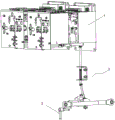
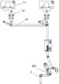
Fig. 1 is a schematic diagram of an interlocking device of a gas-insulated switchgear of the present invention.
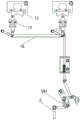
Fig. 2 is a simplified schematic diagram of an interlock arrangement for a gas insulated switchgear of the present invention.
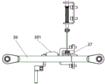
Fig. 3 is a schematic diagram of the interlocking device connecting rod opening of the gas-insulated switchgear of the present invention.
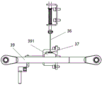
Fig. 4 is a schematic diagram of the connecting rod closing of the interlocking device of the gas-insulated switchgear.
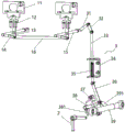
Fig. 5 is a schematic diagram of a three-position switching mechanism isolation position interlock of an interlock device of a gas insulated switchgear of the present invention.
Fig. 6 is a schematic view of a three-position switch mechanism ground state interlock of an interlock device of a gas insulated switchgear of the present invention.
Fig. 7 is a schematic diagram of a single three-position switching mechanism interlock of an interlock device for a gas insulated switchgear of the present invention.
Fig. 8 is a schematic diagram showing practical application of the structure of an interlocking device of a gas-insulated switchgear.
Description of the embodiments
For the purpose of making the objects, technical solutions and advantages of the embodiments of the present invention more apparent, the technical solutions of the embodiments of the present invention will be clearly and completely described below with reference to the accompanying drawings in the embodiments of the present invention, and it is apparent that the described embodiments are some embodiments of the present invention, but not all embodiments of the present invention. The components of the embodiments of the present invention generally described and illustrated in the figures herein may be arranged and designed in a wide variety of different configurations.
Thus, the following detailed description of the embodiments of the invention, as presented in the figures, is not intended to limit the scope of the invention, as claimed, but is merely representative of selected embodiments of the invention. All other embodiments, which can be made by those skilled in the art based on the embodiments of the invention without making any inventive effort, are intended to be within the scope of the invention.
An interlocking device of a gas-insulated switchgear as shown in fig. 1 to 8 comprises a three-position switching mechanism 1 and a closing lever 2; the three-position switch mechanism comprises an interlocking structure 3, wherein the interlocking structure 3 is arranged between the three-position switch mechanism 1 and the closing lever 2, and the action limitation of the closing lever 2 and the three-position switch mechanism 1 is controlled through the interlocking structure 3.
The interlocking structure 3 includes a first swing lever 31, a first link plate 32, a first link 33, a bracket 34, a return spring 35, a second link plate 36, a second link 37, a main pivot shaft 38, and a main link 39; one end of the first swinging rod 31 is fixedly connected to the three-station switch mechanism 1; the other end of the first swing lever 31 is hinged to one end of the first connecting plate 32; the top end of the first connecting rod 33 is hinged with the other end of the first connecting plate 32, the first connecting rod 33 is arranged along the vertical direction, and the other end of the first connecting rod 33 is hinged on the second connecting plate 36; the bracket 34 is of a U-shaped structure, and through holes for accommodating the first connecting rods 33 to pass through along the vertical direction are formed in the two side walls of the bracket 34; the return spring 35 is nested on the first connecting rod 33, one end of the return spring 35 is connected to the first connecting rod 33, and the other end of the return spring 35 is connected to the bracket 34; the top end of the second connecting plate 36 is hinged to the bottom end of the first connecting rod 33, and the bottom end of the second connecting plate 36 is hinged to the second connecting rod 37; the other end of the second connecting rod 37 is fixedly connected to a main rotating shaft 38, and the main rotating shaft 38 is perpendicular to the second connecting rod 37; the first swing lever 31, the first connecting plate 32, the first connecting rod 33 and the second connecting rod 37 are all located in the same plane; an interlocking shaft 381 is arranged on the main rotating shaft 38 and perpendicular to the axis direction of the main rotating shaft 38, and the interlocking shaft 381 is matched with the closing lever 2 to limit the action of the closing lever 2; the main connecting rod 39 is parallel to the main rotating shaft 38 and is arranged on one side of the main rotating shaft 38, the main connecting rod 39 is vertically provided with a interlocking block 391, the main connecting rod 39 can be driven along the horizontal direction, the interlocking block 391 is abutted against the hinge joint of the second connecting rod 37 and the second connecting plate 36, and the rotation of the second connecting rod 37 is limited; or is separated from the hinge joint of the second connecting rod 37 and the second connecting plate 36, so that the second connecting plate 36 can drive the second connecting rod 37 to rotate.
The three-station switch mechanism 1 is provided with a plurality of switch mechanisms; the three-station switch mechanism 1 comprises a mechanism shifting plate 11, a guide plate 12, an interlocking connecting plate 13, an interlocking swinging rod 14 and an interlocking rotary shaft 15; the bottom end of the mechanism shifting plate 11 is connected to the top end of the guide plate 12, the bottom end of the guide plate 12 is hinged to the top end of the interlocking connection plate 13, the bottom end of the interlocking connection plate 13 is hinged to one end of the interlocking swinging rod 14, the other end of the interlocking swinging rod 14 is fixedly connected with the interlocking rotary shaft 15, and the interlocking rotary shaft 15 is vertically arranged on the end part of the interlocking swinging rod 14; the three-position switch mechanisms 1 are connected through a third connecting plate 16 to realize linkage, and two ends of the third connecting plate 16 are respectively hinged at the hinged positions of the interlocking connecting plates 13 and the interlocking swinging rods 14 of the two three-position switch mechanisms 1.
A pivot seat is arranged at the main pivot shaft 38 and is matched with the main pivot shaft 38 to support the main pivot shaft 38.
The working principle of the invention is as follows:
when the three-station switch mechanism is operated manually in isolation or in grounding, the breaker must be always in a brake-separating position and cannot be operated in closing; when the breaker is in the open position, as shown in fig. 3: the main connecting rod moves leftwards from a closing state to a separating state, and the interlocking block fixed on the main connecting rod through the screw also moves to the left side of a second connecting rod of the interlocking device, so that the blocking of the second connecting rod is eliminated by the interlocking block, and the second connecting rod can rotate clockwise;
when the three-position switch mechanism is in manual isolation operation, as shown in fig. 5: the three-station switch mechanism poking plate is manually driven leftwards, the poking plate bevel edge drives the guide plate to move downwards to drive the whole interlocking device to move, the reset spring is compressed, the interlocking shaft rotates clockwise to form locking with the closing lever, the closing lever cannot rotate anticlockwise, and therefore closing operation of the circuit breaker mechanism is prevented.
When the three-position switching mechanism is performing manual grounding operation, as shown in fig. 6: the three-station switch mechanism poking plate is manually driven rightward, and the interlocking shaft and the closing lever are locked in a similar way to prevent the breaker mechanism from closing; in addition, manual isolation or grounding operation is carried out on the line-side three-station switch, and similarly, the interlocking shaft and the closing lever form locking to prevent the breaker mechanism from carrying out closing operation; when the three-station switching mechanism is manually operated, the breaker is closed and locked, so that the breaker is limited to be closed; at the moment, the interlocking device is not contacted with the three-station switching mechanism, and the three-station switching mechanism can be manually operated; the manual operation of the two three-station switch mechanisms after interlocking is not mutually influenced.
When the breaker is in a closing position, the three-station switch cannot be isolated or grounded;
when the circuit breaker is in the closing position, as shown in fig. 4: the main connecting rod moves rightwards from the opening state to the closing state, and the interlocking block fixed on the main connecting rod through the screw also moves right below the second connecting rod of the interlocking device, so that the second connecting rod is limited to rotate clockwise.
When the three-station switching mechanism performs manual isolation operation, the second connecting rod of the interlocking device cannot rotate clockwise, and the whole interlocking transmission system cannot move, so that the three-station switching mechanism cannot perform manual operation; therefore, the function that the three-position switch cannot perform isolation or grounding operation when the circuit breaker is in a closing position is realized.
It will be understood by those skilled in the art that the present invention is not limited to the embodiments described above, and that the above embodiments and descriptions are merely illustrative of the principles of the present invention, and various changes and modifications may be made without departing from the spirit and scope of the invention, which is defined in the appended claims. The scope of the invention is defined by the appended claims and equivalents thereof.
Claims (3)
1. An interlocking device of gas-insulated switchgear comprises a three-position switch mechanism and a closing lever; the method is characterized in that: the three-station switching mechanism comprises an interlocking structure, wherein the interlocking structure is arranged between the three-station switching mechanism and the closing lever, and the action limitation of the closing lever and the three-station switching mechanism is controlled through the interlocking structure;
the interlocking structure comprises a first swinging rod, a first connecting plate, a first connecting rod, a bracket, a reset spring, a second connecting plate, a second connecting rod, a main rotating shaft and a main connecting rod; one end of the first swinging rod is fixedly connected to the three-station switch mechanism; the other end of the first swinging rod is hinged to one end of the first connecting plate; the top end of the first connecting rod is hinged with the other end of the first connecting plate, the first connecting rod is arranged along the vertical direction, and the other end of the first connecting rod is hinged on the second connecting plate; the bracket is of a U-shaped structure, and through holes for accommodating the first connecting rods to pass through along the vertical direction are formed in the two side walls of the bracket; the reset spring is nested on the first connecting rod, one end of the reset spring is connected to the first connecting rod, and the other end of the reset spring is connected to the bracket; the top end of the second connecting plate is hinged to the bottom end of the first connecting rod, and the bottom end of the second connecting plate is hinged to the second connecting rod; the other end of the second connecting rod is fixedly connected to the main rotating shaft, and the main rotating shaft is perpendicular to the second connecting rod; the first swinging rod, the first connecting plate, the first connecting rod and the second connecting rod are all positioned in the same plane; an interlocking shaft is arranged on the main rotating shaft in the direction perpendicular to the axis of the main rotating shaft, and the interlocking shaft is matched with the closing lever to limit the action of the closing lever; the main connecting rod is parallel to the main rotating shaft and is arranged at one side of the main rotating shaft, the main connecting rod is vertically provided with a interlocking block, the main connecting rod can be driven along the horizontal direction, the interlocking block is propped against the hinge joint of the second connecting rod and the second connecting plate, and the rotation of the second connecting rod is limited; or the hinge joint of the second connecting rod and the second connecting plate is separated, so that the second connecting plate can drive the second connecting rod to rotate.
2. An interlocking device for a gas-insulated switchgear as claimed in claim 1, wherein: the three-station switch mechanism is provided with a plurality of three-station switch mechanisms; the three-station switch mechanism comprises a mechanism shifting plate, a guide plate, an interlocking connecting plate, an interlocking swinging rod and an interlocking rotary shaft; the bottom end of the mechanism shifting plate is connected to the top end of the guide plate, the bottom end of the guide plate is hinged to the top end of the interlocking connecting plate, the bottom end of the interlocking connecting plate is hinged to one end of the interlocking swinging plate, the other end of the interlocking swinging rod is fixedly connected with the interlocking rotating shaft, and the interlocking rotating shaft is vertically arranged on the end part of the interlocking swinging rod; the three-station switch mechanisms are connected through a third connecting plate to realize linkage, and two ends of the third connecting plate are respectively hinged at the hinged positions of the interlocking connecting plates and the interlocking swinging rods of the two three-station switch mechanisms.
3. An interlocking device for a gas-insulated switchgear as claimed in claim 1, wherein: the main rotating shaft is provided with a rotating shaft seat which is matched with the main rotating shaft to support the main rotating shaft.
Priority Applications (1)
| Application Number | Priority Date | Filing Date | Title |
|---|---|---|---|
| CN202310228433.1A CN116313588A (en) | 2023-03-10 | 2023-03-10 | Interlocking device of gas-insulated switchgear |
Applications Claiming Priority (1)
| Application Number | Priority Date | Filing Date | Title |
|---|---|---|---|
| CN202310228433.1A CN116313588A (en) | 2023-03-10 | 2023-03-10 | Interlocking device of gas-insulated switchgear |
Publications (1)
| Publication Number | Publication Date |
|---|---|
| CN116313588A true CN116313588A (en) | 2023-06-23 |
Family
ID=86781024
Family Applications (1)
| Application Number | Title | Priority Date | Filing Date |
|---|---|---|---|
| CN202310228433.1A Pending CN116313588A (en) | 2023-03-10 | 2023-03-10 | Interlocking device of gas-insulated switchgear |
Country Status (1)
| Country | Link |
|---|---|
| CN (1) | CN116313588A (en) |
-
2023
- 2023-03-10 CN CN202310228433.1A patent/CN116313588A/en active Pending
Similar Documents
| Publication | Publication Date | Title |
|---|---|---|
| KR101212783B1 (en) | 3-way switch of gas insulated switchgear | |
| EP3407367B1 (en) | 3-way disconnector and earth switch for gas insulated switchgear | |
| KR100990477B1 (en) | Gas insulated switchgear | |
| JPH07505253A (en) | Gas-insulated switchgear equipped with a multi-pole vacuum switch and a multi-pole load disconnector | |
| CN1023673C (en) | Auxiliary control and indicating switch for standard multi-circuit breaker | |
| CN102208759B (en) | Switching device | |
| EP3929955B1 (en) | Load-break or short-circuit current switch | |
| US9685283B2 (en) | Interlock for circuit interrupting device | |
| CN1138291C (en) | Operating device for ground switch for switchgears, especially for moderate voltage ones | |
| CN116313588A (en) | Interlocking device of gas-insulated switchgear | |
| KR200321221Y1 (en) | Development of the compact Disconnecting switch and Earthing switch for the Gas lnsulated Switchgear | |
| CN1083611C (en) | Circuit breaker operating mechanism with wide opening angle | |
| CN217822534U (en) | Operating mechanism for isolating grounding switch and isolating grounding switch | |
| KR100347363B1 (en) | Ds/es system of gas insulated switchgear | |
| JPH08168125A (en) | Switchgear | |
| KR101095016B1 (en) | a 3-postion operating apparatus of Gas Insulated Switchgear | |
| KR100540082B1 (en) | 3 position switch drive mechanism | |
| US9275807B2 (en) | Interlock system for switchgear | |
| JP4682039B2 (en) | Switchgear | |
| CN219476528U (en) | Interlocking mechanism of 24KV solid insulation switch cabinet | |
| JP4261119B2 (en) | Gas insulated switchgear | |
| KR100498558B1 (en) | Gas insulated switch | |
| KR100397567B1 (en) | Gas insulated switchgear | |
| KR100474380B1 (en) | Power transmisson device of c.b. mechanism in g.i.s. | |
| CN115020147A (en) | Transmission mechanism for circuit breaker and related electrical equipment |
Legal Events
| Date | Code | Title | Description |
|---|---|---|---|
| PB01 | Publication | ||
| PB01 | Publication | ||
| SE01 | Entry into force of request for substantive examination | ||
| SE01 | Entry into force of request for substantive examination |