CN116291936A - Piston and marine internal combustion engine - Google Patents
Piston and marine internal combustion engine Download PDFInfo
- Publication number
- CN116291936A CN116291936A CN202211631192.7A CN202211631192A CN116291936A CN 116291936 A CN116291936 A CN 116291936A CN 202211631192 A CN202211631192 A CN 202211631192A CN 116291936 A CN116291936 A CN 116291936A
- Authority
- CN
- China
- Prior art keywords
- piston
- peripheral surface
- cylinder
- main body
- outer peripheral
- Prior art date
- Legal status (The legal status is an assumption and is not a legal conclusion. Google has not performed a legal analysis and makes no representation as to the accuracy of the status listed.)
- Pending
Links
- 238000002485 combustion reaction Methods 0.000 title claims abstract description 105
- 230000002093 peripheral effect Effects 0.000 claims abstract description 155
- 239000011248 coating agent Substances 0.000 claims abstract description 110
- 238000000576 coating method Methods 0.000 claims abstract description 110
- 230000010355 oscillation Effects 0.000 claims description 10
- 239000010802 sludge Substances 0.000 description 33
- 239000000446 fuel Substances 0.000 description 25
- 239000007789 gas Substances 0.000 description 25
- 238000002347 injection Methods 0.000 description 14
- 239000007924 injection Substances 0.000 description 14
- 238000010586 diagram Methods 0.000 description 12
- 230000033001 locomotion Effects 0.000 description 12
- 239000010687 lubricating oil Substances 0.000 description 12
- 239000000463 material Substances 0.000 description 12
- 239000000567 combustion gas Substances 0.000 description 11
- 239000003921 oil Substances 0.000 description 11
- 238000009825 accumulation Methods 0.000 description 10
- 230000000052 comparative effect Effects 0.000 description 10
- 230000002000 scavenging effect Effects 0.000 description 8
- 238000005299 abrasion Methods 0.000 description 7
- 230000003746 surface roughness Effects 0.000 description 6
- 230000000694 effects Effects 0.000 description 5
- 229910052751 metal Inorganic materials 0.000 description 5
- 239000002184 metal Substances 0.000 description 5
- MWUXSHHQAYIFBG-UHFFFAOYSA-N nitrogen oxide Inorganic materials O=[N] MWUXSHHQAYIFBG-UHFFFAOYSA-N 0.000 description 5
- 230000015572 biosynthetic process Effects 0.000 description 4
- 150000002739 metals Chemical class 0.000 description 4
- 238000000034 method Methods 0.000 description 3
- 238000010531 catalytic reduction reaction Methods 0.000 description 2
- 230000006835 compression Effects 0.000 description 2
- 238000007906 compression Methods 0.000 description 2
- 230000001771 impaired effect Effects 0.000 description 2
- 230000035515 penetration Effects 0.000 description 2
- ZOKXTWBITQBERF-UHFFFAOYSA-N Molybdenum Chemical compound [Mo] ZOKXTWBITQBERF-UHFFFAOYSA-N 0.000 description 1
- 239000000919 ceramic Substances 0.000 description 1
- 238000010276 construction Methods 0.000 description 1
- 238000007796 conventional method Methods 0.000 description 1
- 230000008878 coupling Effects 0.000 description 1
- 238000010168 coupling process Methods 0.000 description 1
- 238000005859 coupling reaction Methods 0.000 description 1
- 239000000295 fuel oil Substances 0.000 description 1
- 230000005764 inhibitory process Effects 0.000 description 1
- 230000009545 invasion Effects 0.000 description 1
- 239000007788 liquid Substances 0.000 description 1
- 230000001050 lubricating effect Effects 0.000 description 1
- 238000005461 lubrication Methods 0.000 description 1
- 229910052750 molybdenum Inorganic materials 0.000 description 1
- 239000011733 molybdenum Substances 0.000 description 1
- 239000002245 particle Substances 0.000 description 1
- 238000005498 polishing Methods 0.000 description 1
- 229920001296 polysiloxane Polymers 0.000 description 1
- 230000002265 prevention Effects 0.000 description 1
- 230000002035 prolonged effect Effects 0.000 description 1
- 238000006722 reduction reaction Methods 0.000 description 1
- 238000007789 sealing Methods 0.000 description 1
- 230000003068 static effect Effects 0.000 description 1
Images


Classifications
-
- F—MECHANICAL ENGINEERING; LIGHTING; HEATING; WEAPONS; BLASTING
- F02—COMBUSTION ENGINES; HOT-GAS OR COMBUSTION-PRODUCT ENGINE PLANTS
- F02F—CYLINDERS, PISTONS OR CASINGS, FOR COMBUSTION ENGINES; ARRANGEMENTS OF SEALINGS IN COMBUSTION ENGINES
- F02F3/00—Pistons
- F02F3/0084—Pistons the pistons being constructed from specific materials
-
- F—MECHANICAL ENGINEERING; LIGHTING; HEATING; WEAPONS; BLASTING
- F02—COMBUSTION ENGINES; HOT-GAS OR COMBUSTION-PRODUCT ENGINE PLANTS
- F02F—CYLINDERS, PISTONS OR CASINGS, FOR COMBUSTION ENGINES; ARRANGEMENTS OF SEALINGS IN COMBUSTION ENGINES
- F02F3/00—Pistons
-
- F—MECHANICAL ENGINEERING; LIGHTING; HEATING; WEAPONS; BLASTING
- F02—COMBUSTION ENGINES; HOT-GAS OR COMBUSTION-PRODUCT ENGINE PLANTS
- F02F—CYLINDERS, PISTONS OR CASINGS, FOR COMBUSTION ENGINES; ARRANGEMENTS OF SEALINGS IN COMBUSTION ENGINES
- F02F3/00—Pistons
- F02F3/10—Pistons having surface coverings
-
- F—MECHANICAL ENGINEERING; LIGHTING; HEATING; WEAPONS; BLASTING
- F02—COMBUSTION ENGINES; HOT-GAS OR COMBUSTION-PRODUCT ENGINE PLANTS
- F02F—CYLINDERS, PISTONS OR CASINGS, FOR COMBUSTION ENGINES; ARRANGEMENTS OF SEALINGS IN COMBUSTION ENGINES
- F02F3/00—Pistons
- F02F3/26—Pistons having combustion chamber in piston head
-
- F—MECHANICAL ENGINEERING; LIGHTING; HEATING; WEAPONS; BLASTING
- F02—COMBUSTION ENGINES; HOT-GAS OR COMBUSTION-PRODUCT ENGINE PLANTS
- F02F—CYLINDERS, PISTONS OR CASINGS, FOR COMBUSTION ENGINES; ARRANGEMENTS OF SEALINGS IN COMBUSTION ENGINES
- F02F3/00—Pistons
- F02F3/28—Other pistons with specially-shaped head
-
- F—MECHANICAL ENGINEERING; LIGHTING; HEATING; WEAPONS; BLASTING
- F16—ENGINEERING ELEMENTS AND UNITS; GENERAL MEASURES FOR PRODUCING AND MAINTAINING EFFECTIVE FUNCTIONING OF MACHINES OR INSTALLATIONS; THERMAL INSULATION IN GENERAL
- F16J—PISTONS; CYLINDERS; SEALINGS
- F16J9/00—Piston-rings, e.g. non-metallic piston-rings, seats therefor; Ring sealings of similar construction
- F16J9/12—Details
- F16J9/20—Rings with special cross-section; Oil-scraping rings
-
- F—MECHANICAL ENGINEERING; LIGHTING; HEATING; WEAPONS; BLASTING
- F02—COMBUSTION ENGINES; HOT-GAS OR COMBUSTION-PRODUCT ENGINE PLANTS
- F02F—CYLINDERS, PISTONS OR CASINGS, FOR COMBUSTION ENGINES; ARRANGEMENTS OF SEALINGS IN COMBUSTION ENGINES
- F02F3/00—Pistons
- F02F2003/0007—Monolithic pistons; One piece constructions; Casting of pistons
-
- Y—GENERAL TAGGING OF NEW TECHNOLOGICAL DEVELOPMENTS; GENERAL TAGGING OF CROSS-SECTIONAL TECHNOLOGIES SPANNING OVER SEVERAL SECTIONS OF THE IPC; TECHNICAL SUBJECTS COVERED BY FORMER USPC CROSS-REFERENCE ART COLLECTIONS [XRACs] AND DIGESTS
- Y02—TECHNOLOGIES OR APPLICATIONS FOR MITIGATION OR ADAPTATION AGAINST CLIMATE CHANGE
- Y02T—CLIMATE CHANGE MITIGATION TECHNOLOGIES RELATED TO TRANSPORTATION
- Y02T10/00—Road transport of goods or passengers
- Y02T10/10—Internal combustion engine [ICE] based vehicles
- Y02T10/12—Improving ICE efficiencies
Landscapes
- Engineering & Computer Science (AREA)
- General Engineering & Computer Science (AREA)
- Mechanical Engineering (AREA)
- Chemical & Material Sciences (AREA)
- Combustion & Propulsion (AREA)
- Pistons, Piston Rings, And Cylinders (AREA)
Abstract
The invention provides a piston and a marine internal combustion engine, which can eliminate cavitation and stably ensure lubricity with a cylinder. A piston that reciprocates in a piston axial direction inside a cylinder of an internal combustion engine, the piston comprising: a piston body configured in a cylindrical shape extending in the piston axial direction, the piston body having a crown portion facing the combustion chamber inside the cylinder at one end side in the piston axial direction and a skirt portion at the other end side in the piston axial direction; and a coating film formed on an outer peripheral surface between the crown portion and the skirt portion in the piston main body, and having releasability.
Description
Technical Field
The present invention relates to a piston and an internal combustion engine for a ship.
Background
Conventionally, in an internal combustion engine for a ship mounted on a ship, one or more cylinders are provided in which pistons are housed so as to be reciprocable, and the reciprocating motion of the pistons in the cylinders is converted into a rotational motion of a crank, thereby rotating the crank. In general, a piston ring is provided on an outer circumferential surface (side wall surface) of a piston, and a piston skirt is provided on a lower portion of the piston. In the reciprocating motion of the piston, the top surface (piston crown) of the piston faces the combustion chamber in the cylinder, and the piston ring or the piston skirt is in sliding contact with the inner peripheral surface of the cylinder. Lubricating oil is supplied between the outer peripheral surface of such a piston and the inner peripheral surface of the cylinder, and an oil film is formed from the lubricating oil. The lubricity between these pistons and the cylinder (specifically, lubricity when the piston ring or the piston skirt is in sliding contact with the inner peripheral surface of the cylinder) is ensured by the oil film.
In the combustion chamber in the cylinder, the reciprocating motion of the piston sequentially performs scavenging, supply of combustion gas, and compression. Fuel is injected from a fuel injection valve into a combustion chamber, and the fuel is ignited and burned by a compressed combustion gas in the combustion chamber. The piston continues the reciprocating motion in the cylinder by using the combustion energy of the fuel in the combustion chamber.
Such a piston is in contact with a high-temperature gas (hereinafter referred to as a burned gas) after combustion of a fuel in a combustion chamber during operation of the marine internal combustion engine. For example, the burned gas intrudes into a gap between the outer peripheral surface of the piston and the inner peripheral surface of the cylinder, and the outer peripheral surface of the piston is brought into contact with the burned gas. As a result, hard sludge derived from oil components such as fuel and lubricating oil is deposited on the outer peripheral surface of the piston, and an oil film between the piston and the cylinder is broken by contact with the sludge, resulting in so-called cavitation. As a result, the lubricity of the piston and the cylinder is impaired, and damage due to abrasion between metals of the piston and the cylinder occurs at these sliding contact surfaces.
In recent years, in order to eliminate the cavitation, for example, it is considered to reduce a gap between an outer peripheral surface of a piston and an inner peripheral surface of a cylinder, thereby suppressing invasion of burned gas into the gap and suppressing accumulation of the sludge. As a method for suppressing the accumulation of the sludge, for example, a method has been disclosed in which a polishing prevention ring (frame ring) is provided on the inner circumferential surface of a cylinder, and the sludge is scraped off from the outer circumferential surface of the piston by the frame ring in association with the reciprocation of the piston (see patent document 1).
Prior art literature
Patent literature
Patent document 1: japanese patent laid-open No. 2021-32253
Technical problem to be solved by the invention
However, in the conventional technique described in patent document 1, hard particles of sludge scraped off from the outer peripheral surface of the piston by the frame ring may be caught between the sliding contact surface of the piston ring and the inner peripheral surface of the cylinder or between the sliding contact surface of the piston skirt and the inner peripheral surface of the cylinder. In this case, abrasion wear occurs between the piston and the cylinder, and as a result, there is a possibility that a piston is broken due to a vertical flaw or the like in the piston ring or the piston skirt. In the case of using the above-described frame ring, the inner diameter of the cylinder must be made larger than the inner diameter of the frame ring, and as a result, the clearance between the outer peripheral surface of the piston and the inner peripheral surface of the cylinder increases uselessly, and therefore there is a possibility that the fuel economy performance of the marine internal combustion engine is deteriorated.
Further, as described above, by simply reducing the clearance between the outer peripheral surface of the piston and the inner peripheral surface of the cylinder, penetration of burned gas into the clearance cannot be completely suppressed, and therefore, the above-described inhibition of sludge accumulation may become insufficient, and it is difficult to stably secure lubricity between the piston and the cylinder.
Disclosure of Invention
The present invention has been made in view of the above circumstances, and an object thereof is to provide a piston and an internal combustion engine for a ship, which can eliminate cavitation and stably ensure lubricity with a cylinder.
Technical means for solving the technical problems
In order to solve the above-described problems and achieve the object, a piston according to the present invention reciprocates in a piston axial direction inside a cylinder of an internal combustion engine, the piston including: a piston body configured in a cylindrical shape extending in the piston axial direction, the piston body having a crown portion facing the combustion chamber inside the cylinder at one end side in the piston axial direction and a skirt portion at the other end side in the piston axial direction; and a coating film formed on an outer peripheral surface between the crown portion and the skirt portion in the piston body, the coating film having releasability, an outer diameter of the skirt portion being larger than an outer diameter of the outer peripheral surface of the piston body, and a total size of a film thickness of the coating film and the outer diameter of the outer peripheral surface being smaller than the outer diameter of the skirt portion.
In the piston according to the present invention, the coating film is softer than the inner circumferential surface of the cylinder.
In the piston according to the present invention, the outer peripheral surface of the piston body is provided with a plurality of piston rings aligned in the axial direction of the piston, and the coating film is formed on at least a top land between the crown portion of the outer peripheral surface of the piston body and a top ring of the plurality of piston rings, which is disposed on a side closest to the combustion chamber.
In the piston according to the present invention, the top ring is an airtight ring.
In the piston according to the present invention, the piston body is swingably connected to the crosshead via a piston rod, and the coating film is formed so as to be divided on one end side and the other end side in the swinging direction of the piston body.
The marine internal combustion engine of the present invention further includes: a piston according to any one of the above inventions; and a cylinder that accommodates the piston so as to be movable in a reciprocating manner.
ADVANTAGEOUS EFFECTS OF INVENTION
According to the present invention, the following effects are achieved, and the lubrication between the cylinder and the piston can be ensured stably by eliminating cavitation.
Drawings
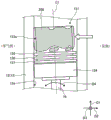
Fig. 1 is a schematic diagram showing an example of a configuration of a marine internal combustion engine to which a piston according to embodiment 1 of the present invention is applied.
Fig. 2 is a schematic diagram showing an example of the structure of a piston according to embodiment 1 of the present invention.
Fig. 3 is a schematic view showing an example of a coating structure of the outer circumferential surface of the piston according to embodiment 1 of the present invention.
Fig. 4 is a schematic diagram for explaining the operation of the piston of the comparative example.
Fig. 5 is a schematic diagram illustrating the operation of the piston according to embodiment 1 of the present invention.
Fig. 6 is a schematic diagram showing an example of the structure of a piston according to embodiment 2 of the present invention.
Fig. 7 is a schematic diagram showing an example of a coating structure of the outer peripheral surface of the piston according to embodiment 2 of the present invention.
Symbol description
1 platen
2 crankshaft
3 crank
4 frame
5 connecting rod
6 sliding plate
7 cross head
8 cross pin
10 internal combustion engine for ship
11 cylinder liner
12 air cylinder
13 cylinder liner
13a inner peripheral surface
14 cylinder cover
15. 15A piston
16 piston rod
17 combustion chamber
18 exhaust valve
19 upper valve device
20 exhaust manifold
21 exhaust pipe
22 fuel injection valve
23 fuel injection pump
24 pinch bolt
151 piston body
152 crown
153 outer peripheral surface
153a top land
153b second land
153c third land
154 skirt portion
155 top ring
156 second ring
157 third ring
160. 160a, 160b coating film
160aa, 160ab, 160ba, 160bb film ends
200 fatlute
C1 piston shaft
D1 height direction
D2 width direction
D3 axial direction
D4 swing direction
Detailed Description
Hereinafter, preferred embodiments of the piston and the marine internal combustion engine according to the present invention will be described in detail with reference to the accompanying drawings. The present invention is not limited to the present embodiment. Note that the drawings are schematic, and the relationship of the dimensions of the elements, the proportions of the elements, and the like may be different from reality. The drawings may include portions having different dimensional relationships and proportions from each other. In the drawings, the same components are denoted by the same reference numerals.
(embodiment 1)
First, a configuration of a marine internal combustion engine to which a piston according to embodiment 1 of the present invention is applied will be described. Fig. 1 is a schematic diagram showing an example of a configuration of a marine internal combustion engine to which a piston according to embodiment 1 of the present invention is applied. The marine internal combustion engine 10 is an example of a cross-head internal combustion engine mounted on a ship, and is a propulsion engine (main engine) that drives a propulsion propeller (neither shown) of the ship to rotate via a propeller shaft. For example, the marine internal combustion engine 10 is a two-stroke diesel engine such as a single-flow exhaust type crosshead diesel engine.
Specifically, as shown in fig. 1, the marine internal combustion engine 10 includes: a platen 1 located at the lower side in the height direction D1, a frame 4 provided on the platen 1, and a cylinder liner 11 provided on the frame 4. The deck plate 1, the frame 4, and the cylinder liner 11 are integrally fastened and fixed by a plurality of coupling members such as tie bolts 24 extending in the height direction D1 (i.e., the up-down direction) of the marine internal combustion engine 10. The marine internal combustion engine 10 further includes: a cylinder 12 provided in the cylinder liner 11, a piston 15 provided in the cylinder 12, and a crankshaft 2 that rotates in conjunction with the reciprocation of the piston 15.
The bedplate 1 forms a crankcase for accommodating a crankshaft 2 and the like of the marine internal combustion engine 10. As shown in fig. 1, a crankshaft 2 having a crank 3 and a bearing portion (not shown) of the crankshaft 2 are provided in a platen 1. The crankshaft 2 is an example of an output shaft that outputs propulsion of a ship, and is rotatably supported by the bearing portion. The lower end of the connecting rod 5 is rotatably connected to the crankshaft 2 via a crank 3.
As shown in fig. 1, a connection rod 5, a slide plate 6, and a cross head 7 are provided inside the frame 4. The frame 4 is disposed on the platen 1 such that the slide plates 6 provided along the piston axial direction are formed in a pair at an interval in the width direction D2 of the marine internal combustion engine 10. The connecting rod 5 is disposed between the pair of slide plates 6 so that the lower end portion thereof is connected to the crank 3 of the crankshaft 2. The crosshead 7 includes: a cross pin 8 connected to the lower end of the piston rod 16, and a cross pin bearing portion (not shown) connected to the upper end of the connecting rod 5. The cross pin 8 is rotatably supported by the cross pin bearing portion. For example, as shown in fig. 1, the crosshead 7 is disposed between the pair of slide plates 6 so that the axial direction (longitudinal direction) of the crosshead pin 8 is in the same direction as the axial direction D3 of the marine internal combustion engine 10. The crosshead 7 is configured to be reciprocable in the longitudinal direction (the height direction D1 in fig. 1) of the pair of slide plates 6 and swingable in the opposite direction (the width direction D2 in fig. 1) of the pair of slide plates 6.
As shown in fig. 1, a cylinder liner 11 is provided at an upper portion of the frame 4, and supports a cylinder 12. As shown in fig. 1, the cylinder 12 is a cylindrical structure (cylinder) composed of a cylinder liner 13 and a cylinder cover 14, and has a combustion chamber 17 for combustion of fuel. The cylinder liner 13 is a cylindrical structure, for example, and is supported on the inner side of the cylinder liner 11. The cylinder cover 14 is fixed to the upper portion of the cylinder liner 13, thereby dividing the inner space (the combustion chamber 17, etc.) of the cylinder liner 13. The piston 15 is provided in the inner space of the cylinder liner 13 so as to face the combustion chamber 17 and is capable of reciprocating in the piston axial direction (see the two-sided arrow in fig. 1) inside the cylinder liner 13. As shown in fig. 1, the upper end of the piston rod 16 is connected to the lower end of the piston 15. The piston rod 16 is connected to the cross pin 8 described above, and is swingable in a direction around the axis of the cross pin 8. That is, the piston 15 can oscillate in the oscillation direction D4 shown in fig. 1.
As shown in fig. 1, an exhaust valve 18 and an upper valve device 19 are provided in the cylinder cover 14. The exhaust valve 18 is a valve that openably closes an exhaust port (exhaust port) of an exhaust pipe 21 that communicates with the combustion chamber 17 in the cylinder 12. The upper valve device 19 is a device that drives the exhaust valve 18 to open and close. The combustion chamber 17 is a space surrounded by such an exhaust valve 18, the cylinder liner 13 described above, the cylinder cover 14, and the piston 15. The marine internal combustion engine 10 further includes an exhaust manifold 20 in the vicinity of the cylinders 12. For example, as shown in fig. 1, the exhaust manifold 20 is disposed on either side of the marine internal combustion engine 10 in the width direction D2 (on the negative side in the width direction D2 in fig. 1). The exhaust manifold 20 receives exhaust gas from the combustion chamber 17 in the cylinder 12 through the exhaust pipe 21, temporarily stores the received exhaust gas, and changes the dynamic pressure of the exhaust gas into the static pressure.
As shown in fig. 1, the marine internal combustion engine 10 includes a fuel injection valve 22 and a fuel injection pump 23. The fuel injection valve 22 is provided in the cylinder cover 14 with its injection port facing into the combustion chamber 17. For example, as shown in fig. 1, the fuel injection pump 23 is disposed on either side (the positive side in the width direction D2 in fig. 1) of the internal combustion engine 10 for a ship in the width direction D2. The fuel injection pump 23 pumps fuel or the like to the fuel injection valve 22 through piping or the like. The fuel injection valve 22 injects a liquid such as fuel pumped from the fuel injection pump 23 into the combustion chamber 17.
In addition to the above, the marine internal combustion engine 10 includes: a supercharger that supercharges combustion gas such as air, a cooler that cools the combustion gas compressed by the supercharger, and a scavenging box that temporarily stores the combustion gas (compressed gas) cooled by the cooler. The combustion gas is supplied from the scavenging box to the internal space of the cylinder liner 13 (for example, the combustion chamber 17) through a scavenging port or the like. Although not particularly shown, the marine internal combustion engine 10 may be provided with an exhaust gas recirculation (EGR: exhaust Gas Recirculation) system and a selective catalytic reduction (SCR: selective Catalytic Reduction) system as devices for reducing nitrogen oxides (NOx) in exhaust gas.
In the marine internal combustion engine 10 having the above-described configuration, the combustion gas is supplied from the scavenging tank to the combustion chamber 17 in the cylinder 12 through the scavenging port or the like. In the combustion chamber 17, the combustion gas is compressed by the piston 15, and the fuel supplied from the fuel injection valve 22 is ignited by the combustion gas to be combusted. Moreover, the piston 15 reciprocates in the piston axial direction inside the cylinder liner 13 by means of energy generated by combustion of fuel in the combustion chamber 17. At this time, when the exhaust valve 18 is operated by the upper valve device 19 to open the exhaust port of the cylinder 12, burned gas remaining in the cylinder liner 13 after combustion of the fuel is discharged as exhaust gas to the exhaust pipe 21. At the same time, new combustion gas is introduced from the scavenging box into the inner space of the cylinder liner 13 through the scavenging port or the like.
When the piston 15 reciprocates in the piston axial direction as described above, the piston may oscillate in the oscillation direction D4 due to the in-cylinder pressure in the combustion chamber 17. That is, the piston rod 16 reciprocates in the piston axial direction while swinging together with the piston 15. In conjunction with this, the crosshead 7 reciprocates along the piston axial direction along the slide plate 6 while swinging. The reciprocating motion of the piston 15 is transmitted to the connecting rod 5 via the cross head 7, and is converted into a rotational motion of the crank 3 connected to the lower end portion of the connecting rod 5. The crankshaft 2 rotates in accordance with the rotation of the crank 3, and the propeller for propulsion of the ship rotates together with the propeller shaft.
In the present specification, for convenience of explanation, the height direction D1, the width direction D2, and the axial direction D3 are set for the marine internal combustion engine 10 as shown in fig. 1, but these directions do not limit the present invention. The height direction D1 of the marine internal combustion engine 10 is a vertical direction, for example, parallel to the direction of reciprocation of the piston 15. The direction of the reciprocating movement of the piston 15 is the piston axial direction, which is the length direction of the piston rod 16. The width direction D2 of the marine internal combustion engine 10 is a direction perpendicular to the height direction D1 and the axial direction D3. The axial direction D3 of the marine internal combustion engine 10 is the longitudinal direction (axial direction) of the crankshaft 2 shown in fig. 1. The height direction D1, the width direction D2, and the axial direction D3 are mutually perpendicular directions. The height direction D1, the width direction D2, and the axial direction D3 are the same for the marine internal combustion engine 10, and are, of course, the same for each of the components (for example, the cylinder 12, the piston 15, and the like) constituting the marine internal combustion engine 10.
The axial direction of the cross pin 8 is the same as the axial direction D3. The swinging direction D4 of the piston 15 is a direction around the axis of the cross pin 8. For example, as shown in fig. 1, one end side in the swing direction D4 is an exhaust side of the marine internal combustion engine 10, and the other end side in the swing direction D4 is a pump side of the marine internal combustion engine 10. The exhaust side of the marine internal combustion engine 10 is a side that discharges exhaust gas with the central axis of the cylinder 12 as a boundary, specifically, a side on which the exhaust manifold 20 is disposed. The pump side of the marine internal combustion engine 10 is a side that supplies fuel into the combustion chamber 17 with the central axis of the cylinder 12 as a boundary, specifically, a side on which the fuel injection pump 23 is disposed.
(Structure of piston)
Next, the structure of the piston 15 according to embodiment 1 of the present invention will be described. Fig. 2 is a schematic diagram showing an example of the structure of a piston according to embodiment 1 of the present invention. Fig. 2 is an enlarged view of the cylinder 12, piston 15, and the like of the marine internal combustion engine 10 shown in fig. 1. Fig. 3 is a schematic view showing an example of a coating structure on the outer peripheral surface of the piston according to embodiment 1 of the present invention. Fig. 3 is a diagram showing the piston 15 shown in fig. 2 viewed from the top surface side. In fig. 3, for convenience of explanation, illustration of piston rings (top ring 155, second ring 156, and third ring 157 in fig. 2) of piston 15 is omitted.
The piston 15 according to embodiment 1 reciprocates in the piston axial direction inside the cylinder 12 of the marine internal combustion engine 10 illustrated in fig. 1, and includes a piston body 151 and a coating film 160 having releasability as shown in fig. 2 and 3. The piston axial direction is a longitudinal direction of the piston axis C1 (hereinafter referred to as a piston axis C1 direction) which is a central axis of the piston 15, and is, for example, the same direction as the longitudinal direction of the piston rod 16. The piston 15 includes a plurality of piston rings on its outer peripheral surface. For example, the piston 15 includes three piston rings, i.e., a top ring 155, a second ring 156, and a third ring 157, as the plurality of piston rings.
The piston main body 151 reciprocates in the cylinder 12 in which the combustion chamber 17 of the marine internal combustion engine 10 (see fig. 1) is formed. Specifically, as shown in fig. 2 and 3, the piston main body 151 is formed in a cylindrical shape extending in the direction of the piston axis C1, and has a crown 152 on one end side (for example, upper side) in the direction of the piston axis C1 and a skirt 154 on the other end side (for example, lower side) in the direction of the piston axis C1. Further, the piston main body 151 has an outer peripheral surface 153 between the crown 152 and the skirt 154 in a direction (circumferential direction) around the piston axis C1. A plurality of piston rings, such as a top ring 155, a second ring 156, and a third ring 157 shown in fig. 2, are provided on the outer peripheral surface 153 of the piston main body 151 in the direction of the piston axis C1.
The piston rod 16 is coupled to the piston body 151 so as to extend from the skirt 154. Although not particularly shown, a pin (not shown) in the same axial direction as the cross pin 8 is provided in the piston main body 151. The upper end of the piston rod 16 is rotatably connected to the pin in the piston main body 151. That is, the piston main body 151 and the piston rod 16 can oscillate in the exhaust side and the pump side in the oscillation direction D4 shown in fig. 2, and the piston main body 151 itself can oscillate in the exhaust side and the pump side in the oscillation direction D4 relative to the piston rod 16.
As shown in fig. 2, such a piston main body 151 is housed inside the cylinder 12, more specifically, inside the cylinder liner 13 constituting the cylindrical portion of the cylinder 12, and reciprocates in the direction of the piston axis C1 along the inner peripheral surface 13a of the cylinder liner 13. Further, the piston axis C1 is an axis (central axis) passing through the center of the piston main body 151 which is circular when viewed from the crown 152 and perpendicular to the radial direction of the piston main body 151. The inner peripheral surface 13a of the cylinder liner 13 is an inner peripheral surface of the cylinder 12 formed of the cylinder liner 13 and the cylinder cover 14.
As shown in fig. 2, the crown 152 forms the top surface of the piston body 151, facing the combustion chamber 17 inside the cylinder 12. For example, as shown in fig. 3, the crown 152 is circular in plan view (when viewed from above in fig. 3) as viewed from the direction of the piston axis C1. In the reciprocation of the piston 15, the crown 152 functions as a compression surface for compressing the combustion gas in the combustion chamber 17, and receives in-cylinder pressure from the combustion chamber 17. Further, as shown in fig. 2, the combustion chamber 17 is a space surrounded by the inner peripheral surface 13a of the cylinder liner 13, the inner wall surface of the cylinder cover 14, and the crown 152.
As shown in fig. 2, the outer peripheral surface 153 of the piston main body 151 is a peripheral surface facing the inner peripheral surface 13a of the cylinder liner 13 throughout the circumferential direction around the piston axis C1, and is located between the crown 152 and the skirt 154. When a plurality of piston rings are provided on the outer peripheral surface 153 of the piston main body 151, the outer peripheral surface 153 is divided into a topmost land (japanese) located between a topmost piston ring of the plurality of piston rings and the crown 152, and an intermediate land (japanese) located between the topmost piston ring and the skirt 154.
For example, when three piston rings are provided on the outer peripheral surface 153 of the piston main body 151, as shown in fig. 2, the outer peripheral surface 153 is divided into a top land 153a, a second land 153b, and a third land 153c. The top land 153a of the outer peripheral surface 153 of the piston main body 151 is an example of the uppermost land, specifically, the outer peripheral surface between the crown 152 and the top ring 155. The second land 153b and the third land 153c are examples of the above-described intermediate land. Specifically, the second land 153b is an outer peripheral surface between the top ring 155 and the second ring 156. The third land 153c is an outer circumferential surface between the second ring 156 and the third ring 157.
The skirt 154 is formed in a cylindrical shape extending in the direction of the piston axis C1, and is provided on the other end side (the side opposite to the crown 152) of the piston main body 151 in the direction of the piston axis C1, as shown in fig. 2. The outer peripheral surface of the skirt 154 faces the inner peripheral surface 13a of the cylinder liner 13 in the circumferential direction around the piston axis C1. As shown in fig. 3, the outer diameter R1 of the skirt 154 is larger than the outer diameter R2 of the outer circumferential surface 153 of the piston main body 151. Such a skirt 154 may contact the inner circumferential surface 13a of the cylinder liner 13 due to the oscillation of the piston main body 151 during the reciprocation of the piston 15. The skirt 154 restricts the rocking (tilting movement) of the piston 15 at the time of the reciprocation of the inside of the cylinder liner 13 by the contact with the inner peripheral surface 13a of the cylinder liner 13. From the standpoint of making the inner peripheral surface 13a of the cylinder liner 13 less likely to be damaged by contact (sliding contact) with the skirt 154, it is preferable that the material of construction of the skirt 154 is softer than the inner peripheral surface 13a of the cylinder liner 13.
The top ring 155, the second ring 156, and the third ring 157 are respectively configured to be provided on the outer peripheral surface 153 of the piston main body 151 and to be in sliding contact with the inner peripheral surface 13a of the cylinder liner 13. Hereinafter, in embodiment 1, the "top ring 155, the second ring 156, and the third ring 157" may be collectively referred to as "a plurality of piston rings".
As shown in fig. 2, the top ring 155 is an example of a piston ring closest to the uppermost layer of the crown 152 among the plurality of piston rings aligned in the direction of the piston axis C1. For example, the top ring 155 is mounted to an annular groove formed along the lower end portion of the top land 153a in the outer circumferential surface 153 of the piston main body 151. As shown in fig. 2, the second ring 156 is an example of a middle layer piston ring located between the uppermost piston ring and the lowermost piston ring of the plurality of piston rings. For example, the second ring 156 is mounted to an annular groove formed along the lower end portion of the second land 153b in the outer circumferential surface 153 of the piston main body 151. As shown in fig. 2, the third ring 157 is an example of a piston ring of the lowest layer of the plurality of piston rings that is farthest from the crown 152 (i.e., closest to the skirt 154). For example, the third ring 157 is mounted to an annular groove formed along the lower end portion of the third land 153c in the outer circumferential surface 153 of the piston main body 151.
The top ring 155, the second ring 156, and the third ring 157 are each formed with a joint (not shown) which is a cut portion of the ring. With this structure, each of the plurality of piston rings has elasticity capable of expanding and contracting the diameter in the radial direction of the piston main body 151. When the piston main body 151 is reciprocatingly housed in the cylinder 12, the plurality of piston rings are each in sliding contact with the inner peripheral surface 13a of the cylinder liner 13 via an oil film of lubricating oil while applying an appropriate surface pressure to the inner peripheral surface 13 a. The sliding contact between the plurality of piston rings and the inner peripheral surface 13a of the cylinder liner 13 ensures the sealing property between the outer peripheral surface 153 of the piston 15 and the inner peripheral surface 13a of the cylinder liner 13.
Here, the top ring 155 of the above-described plurality of piston rings is closest to the combustion chamber 17, and thus receives a high in-cylinder pressure from the combustion chamber 17. From the standpoint of ensuring the above-described sealability by receiving such a high in-cylinder pressure, the top ring 155 is preferably a piston ring having an airtight joint, i.e., an airtight ring having a joint exemplified as a nested structure. In the case where the top ring 155 is an airtight ring, the sealability of the top ring 155 can be further improved. This can suppress penetration of the burned gas from the combustion chamber 17 into the gap between the outer peripheral surface 153 (particularly, the top land 153 a) of the piston 15 and the inner peripheral surface 13a of the cylinder liner 13.
The coating film 160 is a film for suppressing accumulation of sludge on the outer peripheral surface of the piston 15. In detail, the coating film 160 is composed of a coating material having releasability, and for example, as shown in fig. 2, the coating film 160 is formed on the outer peripheral surface 153 between the crown 152 and the skirt 154 in the piston main body 151. In embodiment 1, a plurality of piston rings are provided on the outer peripheral surface 153 of the piston main body 151. In this case, the coating film 160 is formed on at least the top land 153a in the outer circumferential surface 153 of the piston main body 151. For example, as shown in fig. 2, the coating film 160 is formed on the top land 153a in such a manner as to cover the entire area of the top land 153a. As described above, the top land 153a is an outer peripheral surface between the crown 152 and the top ring 155, of the outer peripheral surfaces 153 of the piston main body 151. The top ring 155 is the uppermost piston ring of the plurality of piston rings, which is disposed on the side closest to the combustion chamber 17.
The coating material constituting the coating film 160 has releasability that makes it difficult for sludge to adhere to the outer peripheral surface 153 (in embodiment 1, the top land 153 a) of the target piston main body 151. Examples of such a coating material having releasability include a fluororesin-based coating material, a molybdenum-based coating material, a ceramic-based coating material, and a silicone-based coating material. In particular, since the sludge is derived from an oil component such as lubricating oil, a coating material having oleophobic properties is preferable as the coating material having releasability.
From the standpoint of making the inner peripheral surface of the cylinder 12 less likely to be damaged by contact with the coating film 160, it is preferable that the coating film 160 made of the coating material described above is softer than the inner peripheral surface of the cylinder 12. That is, the hardness of the coating film 160 is preferably lower than the hardness of the inner peripheral surface 13a of the cylinder liner 13. Such a coating film 160 has a hardness of, for example, HB180 or less in brinell hardness.
In addition, the coating film 160 has a necessary heat resistance as a film formed on the outer circumferential surface 153 of the piston main body 151 that reciprocates in a high-temperature environment in the cylinder 12. The heat resistance of the coating film 160 is, for example, 400 ℃.
In order to prevent the inner peripheral surface 13a of the cylinder liner 13 from easily contacting the coating film 160 during the reciprocation or the oscillation of the piston 15, it is preferable that the outer diameter of the coating film 160 is smaller than the outer diameter R1 (see fig. 3) of the skirt 154. That is, as shown in fig. 3, the total dimension R3 of the film thickness K of the coating film 160 and the outer diameter R2 of the outer peripheral surface 153 of the piston main body 151 is preferably smaller than the outer diameter R1 of the skirt 154. In embodiment 1, since the coating film 160 is formed on the top land 153a, the outer diameter R2 is the outer diameter of the top land 153 a. The total dimension R3 is represented by the sum of the outer diameter R2 of the top land 153a and the film thickness (=kx2) of the coating film 160 on both radial sides of the piston main body 151, and is calculated by the following formula (1).
Aggregate size r3=outer diameter r2+film thickness k× … … (1)
For example, the film thickness K of the coating film 160 is preferably 0.2mm or less. The amount of protrusion of the skirt 154 from one side of the outer peripheral surface 153 is half (i.e., = (R1-R2)/2) of the difference between the outer diameter R1 of the skirt 154 and the outer diameter R2 of the outer peripheral surface 153, and is preferably 0.3mm or more and 1.0mm or less.
(action of piston)
Next, the operation of the piston 15 according to embodiment 1 of the present invention will be described. Next, the operation of the piston of the comparative example in which the coating film 160 is not formed on the outer peripheral surface of the piston main body 151 will be described first, and then the operation of the piston 15 of embodiment 1 having the coating film 160 will be described. Fig. 4 is a schematic diagram for explaining the operation of the piston of the comparative example. Fig. 5 is a schematic diagram illustrating the operation of the piston according to embodiment 1 of the present invention.
The piston of the comparative example does not form the coating film 160 on the outer peripheral surface of the top land 153a or the like of the piston main body 151. That is, the structure of the piston of the comparative example is the same as that of the piston 15 of embodiment 1, except that the coating film 160 is not provided. When the piston of the comparative example reciprocates repeatedly inside the cylinder 12, an oil component such as lubricating oil between the cylinder liner 13 and the piston main body 151 is heated by contact with burned gas from the combustion chamber 17 (see fig. 1 and 2), and sludge 200 is generated. Sludge 200 is easily generated and adheres to the top land 153a closest to the combustion chamber 17 in the outer circumferential surface of the piston main body 151. Such sludge 200 is hardened by being deposited on the top land 153a as shown in fig. 4, for example, in association with the reciprocation of the piston main body 151.
In the case where sludge 200 is deposited on the top land 153a of the piston main body 151, since there is a deviation in the thickness of the deposited sludge 200 in the circumferential direction of the top land 153a, a gap between the top land 153a and the inner circumferential surface 13a of the cylinder liner 13 is deviated. Accordingly, the balance of the pressure applied to the top land 153a from the radial direction of the piston main body 151 is broken, thereby causing a load to be applied to the top land 153a biased toward either one of both sides of the oscillation direction D4 of the piston main body 151. For example, as shown by the bold arrow in fig. 4, a load from the pump side toward the exhaust side in the swing direction D4 is applied toward the top land 153a. The piston main body 151 swings (tilts) toward either one of the two sides (the exhaust side in fig. 4) in the swinging direction D4 due to the load.
Here, in the case where the piston main body 151 swings in the swinging direction D4 during the reciprocation in the cylinder 12, the skirt 154 originally comes into sliding contact with the inner peripheral surface 13a of the cylinder liner 13 earlier than the top land 153a, thereby restricting the swinging of the piston main body 151. However, in the piston of the comparative example, as shown in fig. 4, the hard sludge 200 is accumulated on the top land 153a. Therefore, even if the oscillation of the piston main body 151 is restricted by the skirt 154, the sludge 200 on the top land 153a is in sliding contact with the inner peripheral surface 13a of the cylinder liner 13, and cavitation occurs due to the sliding contact of the sludge 200. That is, an oil film of the lubricating oil formed between the inner peripheral surface 13a of the cylinder liner 13 and the outer peripheral surface of the piston main body 151 is broken by the sludge 200. As a result, since the lubricity between the piston and the cylinder liner 13 of the comparative example is impaired, there is an increased risk of damage such as ring surface roughness and skirt surface roughness occurring in the piston of the comparative example. In addition, the sealability between the piston and the cylinder liner 13 of the comparative example is reduced due to the occurrence of the damage, and as a result, the risk of occurrence of gas leakage increases.
The rough ring surface is a vertically striped damage (damage in the reciprocating direction of the piston) caused by abrasion of metals on the inner peripheral surface of the cylinder and the outer peripheral surface of the piston ring. The rough skirt surface is a vertically striped damage caused by abrasion of metals of the inner circumferential surface of the cylinder and the outer circumferential surface of the piston skirt. In addition, gas leakage is a phenomenon in which gas on the combustion chamber side leaks from the outer peripheral surface (damaged gap) of the piston ring, which causes roughness of the ring surface, to the piston skirt side.
As shown in fig. 5, for example, the piston 15 of embodiment 1 includes a coating film 160 on the outer peripheral surface (here, the top land 153 a) of the piston body 151. Due to the releasability of the coating film 160, the sludge 200 is not easily attached to the top land 153a of the sludge 200 which is easily generated in the outer circumferential surface of the piston main body 151.
Even if the piston 15 provided with such a coating film 160 is repeatedly reciprocated inside the cylinder 12, as shown in fig. 5, sludge 200 is hardly or not deposited on the top land 153a of the piston main body 151, that is, the surface of the coating film 160. Accordingly, the clearance between the inner peripheral surface 13a of the cylinder liner 13 and the top land 153a of the piston main body 151 is sufficiently ensured throughout the entire circumferential area of the top land 153 a. Therefore, since pressure is applied to the top land 153a in good balance from the radial direction of the piston main body 151, the piston main body 151 does not move obliquely toward either one of both sides of the swing direction D4 in the reciprocating motion within the cylinder liner 13. In addition, even in the case where the piston body 151 swings in the swinging direction D4 during the reciprocation of the piston 15 in the cylinder 12, the swinging of the piston body 151 is restricted by the skirt 154 before the coating film 160 on the top land 153a is in sliding contact with the inner peripheral surface 13a of the cylinder liner 13, for example, as shown in fig. 5.
Therefore, even if the piston 15 makes any of the reciprocating motion or the swinging motion in the cylinder 12, the gap between the coating film 160 on the top land 153a and the inner peripheral surface 13a of the cylinder liner 13 can be sufficiently ensured over the entire circumferential region of the piston main body 151. As a result, no cavitation is generated between the piston 15 and the cylinder liner 13, and the lubricating film of the lubricating oil is maintained, so that the lubricity between the piston 15 and the cylinder liner 13 is stably maintained. As a result, the risk of damage such as ring surface roughness and skirt surface roughness occurring in the piston 15 is reduced, and the risk of gas leakage occurring between the piston 15 and the cylinder liner 13 is further reduced.
As described above, in embodiment 1 of the present invention, the piston main body 151 of the piston 15 reciprocating in the piston axis C1 direction inside the cylinder 12 of the marine internal combustion engine 10 is configured in a cylindrical shape extending in the piston axis C1 direction, the piston main body 151 has the crown 152 facing the combustion chamber 17 inside the cylinder 12 at one end side in the piston axis C1 direction, and the skirt 154 at the other end side in the piston axis C1 direction, and the coating film 160 having releasability is formed on the outer peripheral surface 153 between the crown 152 and the skirt 154 in the piston main body 151.
Therefore, the coating film 160 makes the outer peripheral surface 153 of the piston main body 151 a surface on which sludge is less likely to adhere, and can suppress accumulation of hard sludge on the outer peripheral surface 153 of the piston main body 151. This ensures a gap between the coating film 160 on the outer peripheral surface 153 and the inner peripheral surface of the cylinder 12 over the entire circumferential area of the outer peripheral surface 153 of the piston main body 151. As a result, when the piston 15 reciprocates in the cylinder 12, the hard sludge can be prevented from sliding in contact with the oil film of the lubricating oil on the inner peripheral surface of the cylinder 12, and thus cavitation between the cylinder 12 and the piston 15 can be eliminated, and the formation of the oil film can be stabilized, so that lubricity between the cylinder 12 and the piston 15 can be ensured stably. Further, the metal contact between the cylinder 12 and the piston 15 can be prevented, so that the risk of damage such as ring surface roughness and skirt surface roughness due to abrasion of these metals is reduced in the piston 15, and further, the risk of gas leakage between the cylinder 12 and the piston 15 can be reduced. Further, since an oil film of the lubricating oil is easily held on the inner peripheral surface of the cylinder 12 (the inner peripheral surface 13a of the cylinder liner 13), it is possible to contribute to a reduction in the consumption amount of the lubricating oil.
In embodiment 1 of the present invention, a marine internal combustion engine 10 is configured, and the marine internal combustion engine 10 includes the piston 15 described above, and a cylinder 12 that houses the piston 15 so as to be reciprocable. Therefore, the above-described operational effects of the piston 15 can be enjoyed, whereby the service life of the cylinder 12 and the piston 15 can be prolonged and the frequency of replacement of them can be reduced.
In embodiment 1 of the present invention, the outer diameter R1 of the skirt 154 is made larger than the outer diameter R2 of the outer peripheral surface 153 of the piston main body 151, and the total dimension R3 of the film thickness K of the coating film 160 and the outer diameter R2 of the outer peripheral surface 153 of the piston main body 151 is made smaller than the outer diameter R1 of the skirt 154. Therefore, the gap between the coating film 160 and the inner peripheral surface of the cylinder 12 can be made larger than the gap between the skirt 154 and the inner peripheral surface of the cylinder 12 over the entire circumferential area of the outer peripheral surface 153 of the piston main body 151. Accordingly, even when the piston body 151 swings in the swinging direction D4, the swinging of the piston body 151 can be restricted by the contact of the skirt 154 with the inner peripheral surface of the cylinder 12 in advance, and the sliding contact of the coating film 160 with the inner peripheral surface of the cylinder 12 can be easily avoided, because the coating film 160 on the outer peripheral surface 153 of the piston body 151 and the inner peripheral surface of the cylinder 12 can be easily avoided when the piston reciprocates in the cylinder 12.
In embodiment 1 of the present invention, the coating film 160 on the outer peripheral surface 153 of the piston main body 151 is configured to be softer than the inner peripheral surface of the cylinder 12. Therefore, even if the coating film 160 is in sliding contact with the inner peripheral surface of the cylinder 12 at the time of reciprocation or oscillation of the piston 15 in the cylinder 12, abrasion of the inner peripheral surface of the cylinder 12 can be suppressed to the minimum. This can suppress the occurrence of damage due to abrasion of the inner peripheral surface of the cylinder 12.
In embodiment 1 of the present invention, a plurality of piston rings aligned in the direction of the piston axis C1 are provided on the outer peripheral surface 153 of the piston main body 151, and a coating film 160 is formed on at least the top land 153a, which is the outer peripheral surface between the crown 152 in the outer peripheral surface 153 of the piston main body 151 and the top ring 155 of the plurality of piston rings provided on the side closest to the combustion chamber 17. Therefore, at least the top land 153a of the outer peripheral surface 153 of the piston main body 151, which is at the highest temperature in the environment, is likely to generate sludge by the coating film 160, and is a surface to which sludge is unlikely to adhere. This can effectively suppress the accumulation of the hard sludge on the outer peripheral surface 153 of the piston main body 151.
In embodiment 1 of the present invention, the top ring 155 of the plurality of piston rings is made of an airtight ring. Therefore, the tightness of the top ring 155, which receives the highest pressure from the combustion chamber 17 side, among the plurality of piston rings can be further improved. This makes it possible to prevent the burnt gas from the combustion chamber 17 from easily entering the gap between the inner peripheral surface of the cylinder 12 and the top land 153a of the piston main body 151. As a result, since the lubricating oil between the inner peripheral surface of the cylinder 12 and the top land 153a is not easily heated by the burned gas, the generation of sludge between the inner peripheral surface of the cylinder 12 and the top land 153a can be suppressed, and the accumulation of sludge on the outer peripheral surface 153 of the piston main body 151 can be facilitated to be suppressed.
(embodiment 2)
Next, a piston and a marine internal combustion engine according to embodiment 2 of the present invention will be described. Fig. 6 is a schematic diagram showing an example of the structure of a piston according to embodiment 2 of the present invention. Fig. 7 is a schematic view showing an example of a coating structure on the outer peripheral surface of the piston according to embodiment 2 of the present invention. Fig. 7 shows a view of the piston 15A shown in fig. 6 from the top surface side. In fig. 7, for convenience of explanation, illustration of piston rings (top ring 155, second ring 156, and third ring 157 in fig. 6) of piston 15A is omitted.
As shown in fig. 6 and 7, the piston 15A according to embodiment 2 of the present invention includes coating films 160a and 160b instead of the coating film 160 of the piston 15 according to embodiment 1 described above. Although not particularly shown, the marine internal combustion engine according to embodiment 2 of the present invention includes a piston 15A instead of the piston 15 of the marine internal combustion engine 10 according to embodiment 1 described above. Other structures are the same as those of embodiment 1, and the same reference numerals are given to the same structural parts.
Both of the coating films 160a and 160b are films for suppressing accumulation of sludge on the outer peripheral surface of the piston 15A. Specifically, the coating films 160a and 160b are made of a coating material having the same releasability as that of the above-described embodiment 1, and for example, as shown in fig. 6 and 7, the coating films 160a and 160b are formed so as to be divided on one end side and the other end side in the swinging direction D4 of the piston main body 151. As described above, the piston main body 151 is swingably connected to the crosshead 7 (see fig. 1) via the piston rod 16.
The coating film 160a on one side is a coating film on one side (the exhaust side in fig. 6 and 7) in the swinging direction D4 of the piston main body 151. Specifically, as shown in fig. 6 and 7, the coating film 160a is formed on the outer peripheral surface of the piston main body 151 on the exhaust side in the swinging direction D4. In particular, in the piston main body 151 in which a plurality of piston rings are provided on the outer peripheral surface 153, the coating film 160a is formed on at least the top land 153a (hereinafter, referred to as the top land on the exhaust side) in the outer peripheral surface on the exhaust side.
More specifically, as shown in fig. 7, the outer peripheral surface on the exhaust side is an outer peripheral surface on the exhaust side in the rocking direction D4, of the outer peripheral surfaces 153 of the piston main body 151, which is located on the boundary with the axial direction D3 of the cross pin 8 (see fig. 1) orthogonal to the piston axis C1. In embodiment 2, the coating film 160a is formed on, for example, the top land on the exhaust side in the outer peripheral surface of the exhaust side thus distinguished, and covers the top land on the exhaust side.
The formation region of the coating film 160a is set, for example, in a region where the clearance between the outer peripheral surface 153 of the piston main body 151 and the inner peripheral surface 13a of the cylinder liner 13 in the exhaust side in the swing direction D4 is equal to or smaller than a predetermined value.
Specifically, as shown in fig. 7, the coating film 160a is formed in an arc-shaped region centered on the piston axis C1 and having a predetermined angle θ1 and an angle θ2 around the piston axis C1. The angle θ1 is an angle formed by a straight line L1 at one end side in the circumferential direction of the coating film 160a and the swing direction D4. The angle θ2 is an angle formed by the line L2 at the other end side in the circumferential direction of the coating film 160a and the swing direction D4. These angles θ1 and θ2 are angles in opposite directions to each other. The straight line L1 is a straight line that is in contact with the film end 160aa, which is one end of the coating film 160a in the circumferential direction, and is orthogonal to the piston axis C1. The straight line L2 is a straight line that meets the other end portion of the coating film 160a in the circumferential direction, that is, the film end portion 160ab, and is orthogonal to the piston axis C1. The coating film 160a is formed on the top land on the exhaust side in such a manner that the absolute value of the angle θ1 on one end side is less than 90 degrees and the absolute value of the angle θ2 on the other end side is less than 90 degrees.
The other coating film 160b is a coating film on the opposite side (pump side in fig. 6 and 7) to the above-described coating film 160a in the swinging direction D4 of the piston main body 151. Specifically, as shown in fig. 6 and 7, the coating film 160b is formed on the pump-side outer peripheral surface in the swinging direction D4 of the outer peripheral surface 153 of the piston main body 151. In particular, in the piston main body 151 in which a plurality of piston rings are provided on the outer peripheral surface 153, the coating film 160b is formed on at least the top land 153a (hereinafter, referred to as the top land on the pump side) in the outer peripheral surface on the pump side.
More specifically, as shown in fig. 7, the pump-side outer peripheral surface is a pump-side outer peripheral surface located in the oscillating direction D4 with the above-described axial direction D3 as a boundary, of the outer peripheral surfaces 153 of the piston main body 151. In embodiment 2, the coating film 160b is formed on, for example, the top land on the pump side in the outer peripheral surface of the pump side thus distinguished, and covers the top land on the pump side.
The formation region of the coating film 160b is set, for example, in a region where the clearance between the outer peripheral surface 153 of the piston main body 151 and the inner peripheral surface 13a of the cylinder liner 13 in the pump side in the swing direction D4 is equal to or smaller than a predetermined value.
Specifically, as shown in fig. 7, the coating film 160b is formed in an arc-shaped region centered on the piston axis C1 and having a predetermined angle θ3 and an angle θ4 around the piston axis C1. The angle θ3 is an angle formed by the straight line L3 at one end side in the circumferential direction of the coating film 160b and the swing direction D4. The angle θ4 is an angle formed by the line L4 at the other end side in the circumferential direction of the coating film 160b and the swing direction D4. These angles θ3 and θ4 are angles in opposite directions to each other. The straight line L3 is a straight line that is in contact with the film end 160ba, which is one end of the coating film 160b in the circumferential direction, and is orthogonal to the piston axis C1. The straight line L4 is a straight line that meets the other end portion of the coating film 160b in the circumferential direction, that is, the film end portion 160bb, and is orthogonal to the piston axis C1. The coating film 160b is formed on the top land on the pump side in such a manner that the absolute value of the angle θ3 on one end side is less than 90 degrees and the absolute value of the angle θ4 on the other end side is less than 90 degrees.
In addition, from the viewpoint of reducing the cost required for forming the coating films 160a and 160b, the above-mentioned angles θ1 to θ4 are preferably smaller. Further, from the viewpoint of making the coating film 160a film that effectively suppresses the accumulation of sludge, the absolute value of each of the angles θ1 to θ4 is preferably 45 degrees or more.
The coating films 160a and 160b of embodiment 2 have the same hardness, heat resistance, film thickness, and other characteristics as the coating film 160 of embodiment 1. In addition, as in embodiment 1 described above, it is preferable that the total dimension R3 of the film thickness K of the coating films 160a, 160b and the outer diameter R2 of the outer peripheral surface 153 of the piston main body 151 is smaller than the outer diameter R1 of the skirt 154.
As described above, in embodiment 2 of the present invention, the coating films 160a and 160b are formed on the outer peripheral surface 153 of the piston main body 151 swingably connected to the crosshead 7 via the piston rod 16 so as to be divided between one end side and the other end side in the swinging direction D4 of the piston main body 151, and the other is the same as embodiment 1. Therefore, the same operational effects as those of embodiment 1 described above are enjoyed, and the formation range of the coating films 160a, 160b can be reduced in the outer peripheral surface 153 of the piston main body 151 to a first region in which the clearance between the one end side in the swinging direction D4 and the inner peripheral surface of the cylinder 12 is equal to or smaller than a predetermined value and a second region in which the clearance between the other end side in the swinging direction D4 and the inner peripheral surface of the cylinder 12 is equal to or smaller than a predetermined value. This ensures the effect of suppressing the accumulation of sludge by the coating films 160a and 160b, and reduces the cost required for forming the coating films.
In embodiments 1 and 2 described above, the coating film is formed on the uppermost land (top land 153 a) in the outer peripheral surface 153 of the piston main body 151, but the present invention is not limited thereto. For example, the coating film may be formed only on the uppermost land or on both the uppermost land and the intermediate land on the outer peripheral surface 153 of the piston main body 151.
In embodiments 1 and 2 described above, three piston rings are illustrated as an example of a plurality of piston rings provided on the outer peripheral surface 153 of the piston main body 151, but the present invention is not limited thereto. For example, one piston ring may be provided on the outer peripheral surface 153 of the piston main body 151, or two or more piston rings may be provided in an array in the reciprocating direction (piston axial direction) of the piston main body 151.
In embodiments 1 and 2 described above, the marine internal combustion engine is exemplified as an example of the internal combustion engine to which the piston of the present invention is applied, but the present invention is not limited to this. For example, the piston of the present invention may be applied to an internal combustion engine other than a marine internal combustion engine such as an engine of a vehicle.
The present invention is not limited to embodiments 1 and 2 described above. The present invention also includes a configuration in which the above-described components are appropriately combined. In addition, other embodiments, examples, application techniques, and the like, which are completed based on the above-described embodiments 1 and 2, by those skilled in the art, are all included in the scope of the present invention.
Claims (8)
1. A piston that reciprocates in a piston axial direction in a cylinder of an internal combustion engine, comprising:
a piston body configured in a cylindrical shape extending in the piston axial direction, the piston body having a crown portion facing the combustion chamber inside the cylinder at one end side in the piston axial direction and a skirt portion at the other end side in the piston axial direction; and
a coating film formed on an outer peripheral surface between the crown portion and the skirt portion in the piston main body and having releasability,
the outer diameter of the skirt portion is larger than the outer diameter of the outer circumferential surface of the piston main body,
the total size of the film thickness of the coating film and the outer diameter of the outer peripheral surface is smaller than the outer diameter of the skirt portion.
2. A piston as set forth in claim 1 wherein,
the coating film is softer than the inner peripheral surface of the cylinder.
3. A piston as set forth in claim 1 wherein,
a plurality of piston rings arranged along the axial direction of the piston are arranged on the outer peripheral surface of the piston main body,
the coating film is formed at least on a top land, which is an outer peripheral surface between the crown portion and a top ring of the plurality of piston rings, which is disposed on a side closest to the combustion chamber, among the outer peripheral surfaces of the piston main body.
4. A piston as set forth in claim 2 wherein,
a plurality of piston rings arranged along the axial direction of the piston are arranged on the outer peripheral surface of the piston main body,
the coating film is formed at least on a top land, which is an outer peripheral surface between the crown portion and a top ring of the plurality of piston rings, which is disposed on a side closest to the combustion chamber, among the outer peripheral surfaces of the piston main body.
5. A piston as set forth in claim 3 wherein,
the top ring is an airtight ring.
6. The piston of claim 4 wherein the piston is configured to move between a closed position,
the top ring is an airtight ring.
7. A piston as claimed in any one of claims 1 to 6, wherein,
the piston body is connected with the cross head in a freely swinging manner through a piston rod,
the coating film is formed in a divided manner on one end side and the other end side in the oscillation direction of the piston main body.
8. An internal combustion engine for a ship, comprising:
the piston of any one of claims 1 to 7; and
and a cylinder that accommodates the piston so as to be movable in a reciprocating manner.
Applications Claiming Priority (2)
| Application Number | Priority Date | Filing Date | Title |
|---|---|---|---|
| JP2021-206450 | 2021-12-20 | ||
| JP2021206450A JP2023091625A (en) | 2021-12-20 | 2021-12-20 | Piston and marine internal combustion engine |
Publications (1)
| Publication Number | Publication Date |
|---|---|
| CN116291936A true CN116291936A (en) | 2023-06-23 |
Family
ID=86793017
Family Applications (1)
| Application Number | Title | Priority Date | Filing Date |
|---|---|---|---|
| CN202211631192.7A Pending CN116291936A (en) | 2021-12-20 | 2022-12-19 | Piston and marine internal combustion engine |
Country Status (3)
| Country | Link |
|---|---|
| JP (1) | JP2023091625A (en) |
| KR (1) | KR20230094150A (en) |
| CN (1) | CN116291936A (en) |
Family Cites Families (1)
| Publication number | Priority date | Publication date | Assignee | Title |
|---|---|---|---|---|
| DE102019122878A1 (en) | 2019-08-27 | 2021-03-04 | Man Energy Solutions Se | Pistons and cylinders of an internal combustion engine and internal combustion engine |
-
2021
- 2021-12-20 JP JP2021206450A patent/JP2023091625A/en active Pending
-
2022
- 2022-12-12 KR KR1020220172623A patent/KR20230094150A/en unknown
- 2022-12-19 CN CN202211631192.7A patent/CN116291936A/en active Pending
Also Published As
| Publication number | Publication date |
|---|---|
| KR20230094150A (en) | 2023-06-27 |
| JP2023091625A (en) | 2023-06-30 |
Similar Documents
| Publication | Publication Date | Title |
|---|---|---|
| US20090020958A1 (en) | Methods and apparatus for operating an internal combustion engine | |
| KR101894085B1 (en) | Crosshead engine | |
| RU2600834C2 (en) | Internal combustion engine piston sealing assembly | |
| US7931003B2 (en) | Reciprocating engine | |
| US7246552B2 (en) | Piston having asymmetrical pin bore slot placement | |
| CN116291936A (en) | Piston and marine internal combustion engine | |
| US10760526B2 (en) | Piston for internal combustion engine | |
| KR20230071105A (en) | Piston ring for use in a ring pack in a piston of a large two-stroke turbo-charged uniflow-scavenged internal combustion engine with crossheads | |
| US9194327B2 (en) | Cylinder liner with slots | |
| US10240559B2 (en) | Piston arrangement and internal combustion engine | |
| US20080271597A1 (en) | Methods and apparatus for operating an internal combustion engine | |
| US9004041B2 (en) | High-load thrust bearing | |
| JP4661831B2 (en) | Piston and internal combustion engine | |
| JP6387237B2 (en) | Piston ring and engine including the piston ring | |
| CN112302810B (en) | Diesel engine for ship | |
| JP7236221B2 (en) | marine diesel engine | |
| JP2022088969A (en) | Fuel injection valve and marine internal combustion engine | |
| KR20220067512A (en) | Piston and internal combustion engine for ship | |
| JP6480709B2 (en) | Piston ring and engine including the piston ring | |
| US20160084193A1 (en) | Cylinder liner having flange with annular groove | |
| CN116892461A (en) | Piston and marine internal combustion engine | |
| FI128417B (en) | Cylinder liner with slots | |
| JP2019108804A (en) | Cylinder block | |
| KR19980083123A (en) | Piston ring with multiple oil drain holes | |
| JP2011169204A (en) | Seal structure of piston |
Legal Events
| Date | Code | Title | Description |
|---|---|---|---|
| PB01 | Publication | ||
| PB01 | Publication | ||
| SE01 | Entry into force of request for substantive examination | ||
| SE01 | Entry into force of request for substantive examination |