CN116250238A - Method and apparatus for encoding and decoding one or more views of a scene - Google Patents
Method and apparatus for encoding and decoding one or more views of a scene Download PDFInfo
- Publication number
- CN116250238A CN116250238A CN202180067571.5A CN202180067571A CN116250238A CN 116250238 A CN116250238 A CN 116250238A CN 202180067571 A CN202180067571 A CN 202180067571A CN 116250238 A CN116250238 A CN 116250238A
- Authority
- CN
- China
- Prior art keywords
- view
- block
- views
- image data
- segmentation mask
- Prior art date
- Legal status (The legal status is an assumption and is not a legal conclusion. Google has not performed a legal analysis and makes no representation as to the accuracy of the status listed.)
- Pending
Links
- 238000000034 method Methods 0.000 title claims abstract description 61
- 230000011218 segmentation Effects 0.000 claims abstract description 114
- 230000006835 compression Effects 0.000 claims description 42
- 238000007906 compression Methods 0.000 claims description 41
- 238000013139 quantization Methods 0.000 claims description 15
- 238000004590 computer program Methods 0.000 claims description 8
- 238000004806 packaging method and process Methods 0.000 claims description 5
- 238000012856 packing Methods 0.000 description 20
- 230000000007 visual effect Effects 0.000 description 6
- 238000010586 diagram Methods 0.000 description 5
- 230000008569 process Effects 0.000 description 4
- 230000008901 benefit Effects 0.000 description 3
- 230000001934 delay Effects 0.000 description 2
- 238000005192 partition Methods 0.000 description 2
- 238000012545 processing Methods 0.000 description 2
- 238000013459 approach Methods 0.000 description 1
- 230000009286 beneficial effect Effects 0.000 description 1
- 230000005540 biological transmission Effects 0.000 description 1
- 230000008859 change Effects 0.000 description 1
- 239000002131 composite material Substances 0.000 description 1
- 239000000470 constituent Substances 0.000 description 1
- 230000006837 decompression Effects 0.000 description 1
- 230000003111 delayed effect Effects 0.000 description 1
- 230000001419 dependent effect Effects 0.000 description 1
- 238000009792 diffusion process Methods 0.000 description 1
- 125000001475 halogen functional group Chemical group 0.000 description 1
- 238000002156 mixing Methods 0.000 description 1
- 239000000203 mixture Substances 0.000 description 1
- 238000012986 modification Methods 0.000 description 1
- 230000004048 modification Effects 0.000 description 1
- 230000003287 optical effect Effects 0.000 description 1
- 230000002093 peripheral effect Effects 0.000 description 1
- 230000009467 reduction Effects 0.000 description 1
- 238000000926 separation method Methods 0.000 description 1
- 238000012549 training Methods 0.000 description 1
Images


Classifications
-
- H—ELECTRICITY
- H04—ELECTRIC COMMUNICATION TECHNIQUE
- H04N—PICTORIAL COMMUNICATION, e.g. TELEVISION
- H04N19/00—Methods or arrangements for coding, decoding, compressing or decompressing digital video signals
- H04N19/10—Methods or arrangements for coding, decoding, compressing or decompressing digital video signals using adaptive coding
- H04N19/102—Methods or arrangements for coding, decoding, compressing or decompressing digital video signals using adaptive coding characterised by the element, parameter or selection affected or controlled by the adaptive coding
- H04N19/124—Quantisation
- H04N19/126—Details of normalisation or weighting functions, e.g. normalisation matrices or variable uniform quantisers
-
- H—ELECTRICITY
- H04—ELECTRIC COMMUNICATION TECHNIQUE
- H04N—PICTORIAL COMMUNICATION, e.g. TELEVISION
- H04N19/00—Methods or arrangements for coding, decoding, compressing or decompressing digital video signals
- H04N19/10—Methods or arrangements for coding, decoding, compressing or decompressing digital video signals using adaptive coding
- H04N19/102—Methods or arrangements for coding, decoding, compressing or decompressing digital video signals using adaptive coding characterised by the element, parameter or selection affected or controlled by the adaptive coding
- H04N19/132—Sampling, masking or truncation of coding units, e.g. adaptive resampling, frame skipping, frame interpolation or high-frequency transform coefficient masking
-
- H—ELECTRICITY
- H04—ELECTRIC COMMUNICATION TECHNIQUE
- H04N—PICTORIAL COMMUNICATION, e.g. TELEVISION
- H04N19/00—Methods or arrangements for coding, decoding, compressing or decompressing digital video signals
- H04N19/10—Methods or arrangements for coding, decoding, compressing or decompressing digital video signals using adaptive coding
- H04N19/102—Methods or arrangements for coding, decoding, compressing or decompressing digital video signals using adaptive coding characterised by the element, parameter or selection affected or controlled by the adaptive coding
- H04N19/119—Adaptive subdivision aspects, e.g. subdivision of a picture into rectangular or non-rectangular coding blocks
-
- H—ELECTRICITY
- H04—ELECTRIC COMMUNICATION TECHNIQUE
- H04N—PICTORIAL COMMUNICATION, e.g. TELEVISION
- H04N19/00—Methods or arrangements for coding, decoding, compressing or decompressing digital video signals
- H04N19/10—Methods or arrangements for coding, decoding, compressing or decompressing digital video signals using adaptive coding
- H04N19/134—Methods or arrangements for coding, decoding, compressing or decompressing digital video signals using adaptive coding characterised by the element, parameter or criterion affecting or controlling the adaptive coding
- H04N19/167—Position within a video image, e.g. region of interest [ROI]
-
- H—ELECTRICITY
- H04—ELECTRIC COMMUNICATION TECHNIQUE
- H04N—PICTORIAL COMMUNICATION, e.g. TELEVISION
- H04N19/00—Methods or arrangements for coding, decoding, compressing or decompressing digital video signals
- H04N19/10—Methods or arrangements for coding, decoding, compressing or decompressing digital video signals using adaptive coding
- H04N19/169—Methods or arrangements for coding, decoding, compressing or decompressing digital video signals using adaptive coding characterised by the coding unit, i.e. the structural portion or semantic portion of the video signal being the object or the subject of the adaptive coding
- H04N19/17—Methods or arrangements for coding, decoding, compressing or decompressing digital video signals using adaptive coding characterised by the coding unit, i.e. the structural portion or semantic portion of the video signal being the object or the subject of the adaptive coding the unit being an image region, e.g. an object
- H04N19/172—Methods or arrangements for coding, decoding, compressing or decompressing digital video signals using adaptive coding characterised by the coding unit, i.e. the structural portion or semantic portion of the video signal being the object or the subject of the adaptive coding the unit being an image region, e.g. an object the region being a picture, frame or field
-
- H—ELECTRICITY
- H04—ELECTRIC COMMUNICATION TECHNIQUE
- H04N—PICTORIAL COMMUNICATION, e.g. TELEVISION
- H04N19/00—Methods or arrangements for coding, decoding, compressing or decompressing digital video signals
- H04N19/10—Methods or arrangements for coding, decoding, compressing or decompressing digital video signals using adaptive coding
- H04N19/169—Methods or arrangements for coding, decoding, compressing or decompressing digital video signals using adaptive coding characterised by the coding unit, i.e. the structural portion or semantic portion of the video signal being the object or the subject of the adaptive coding
- H04N19/17—Methods or arrangements for coding, decoding, compressing or decompressing digital video signals using adaptive coding characterised by the coding unit, i.e. the structural portion or semantic portion of the video signal being the object or the subject of the adaptive coding the unit being an image region, e.g. an object
- H04N19/176—Methods or arrangements for coding, decoding, compressing or decompressing digital video signals using adaptive coding characterised by the coding unit, i.e. the structural portion or semantic portion of the video signal being the object or the subject of the adaptive coding the unit being an image region, e.g. an object the region being a block, e.g. a macroblock
-
- H—ELECTRICITY
- H04—ELECTRIC COMMUNICATION TECHNIQUE
- H04N—PICTORIAL COMMUNICATION, e.g. TELEVISION
- H04N19/00—Methods or arrangements for coding, decoding, compressing or decompressing digital video signals
- H04N19/10—Methods or arrangements for coding, decoding, compressing or decompressing digital video signals using adaptive coding
- H04N19/169—Methods or arrangements for coding, decoding, compressing or decompressing digital video signals using adaptive coding characterised by the coding unit, i.e. the structural portion or semantic portion of the video signal being the object or the subject of the adaptive coding
- H04N19/184—Methods or arrangements for coding, decoding, compressing or decompressing digital video signals using adaptive coding characterised by the coding unit, i.e. the structural portion or semantic portion of the video signal being the object or the subject of the adaptive coding the unit being bits, e.g. of the compressed video stream
-
- H—ELECTRICITY
- H04—ELECTRIC COMMUNICATION TECHNIQUE
- H04N—PICTORIAL COMMUNICATION, e.g. TELEVISION
- H04N19/00—Methods or arrangements for coding, decoding, compressing or decompressing digital video signals
- H04N19/46—Embedding additional information in the video signal during the compression process
-
- H—ELECTRICITY
- H04—ELECTRIC COMMUNICATION TECHNIQUE
- H04N—PICTORIAL COMMUNICATION, e.g. TELEVISION
- H04N19/00—Methods or arrangements for coding, decoding, compressing or decompressing digital video signals
- H04N19/50—Methods or arrangements for coding, decoding, compressing or decompressing digital video signals using predictive coding
- H04N19/597—Methods or arrangements for coding, decoding, compressing or decompressing digital video signals using predictive coding specially adapted for multi-view video sequence encoding
-
- H—ELECTRICITY
- H04—ELECTRIC COMMUNICATION TECHNIQUE
- H04N—PICTORIAL COMMUNICATION, e.g. TELEVISION
- H04N21/00—Selective content distribution, e.g. interactive television or video on demand [VOD]
- H04N21/20—Servers specifically adapted for the distribution of content, e.g. VOD servers; Operations thereof
- H04N21/21—Server components or server architectures
- H04N21/218—Source of audio or video content, e.g. local disk arrays
- H04N21/2187—Live feed
Abstract
Methods for encoding and decoding image or video data comprising two or more views (10) of a scene are provided. The encoding method comprises obtaining (11), for each of the two or more views, a respective block segmentation mask (12) of the view and block image data (13) of the view. The encoding method further includes: generating (14) at least one packed frame (40) of the two or more block segmentation masks and the block image data comprising the two or more views; and encoding (15) the at least one packetized frame into at least one bitstream (16). Each view is divided into blocks of pixels (30), and the block segmentation mask indicates which blocks of pixels belong to a region of interest (31) in the view. The block image data includes the pixel blocks belonging to the region of interest. Corresponding encoders, decoders and bitstreams are also provided.
Description
Technical Field
The present invention relates to decoding of image or video data of one or more views of a scene. The present invention relates in particular to methods and apparatus for encoding and decoding video sequences for Virtual Reality (VR) or immersive video applications captured from multiple viewpoints.
Background
Virtual reality can be a very immersive way of viewing images or videos of a scene. When using virtual reality to view images or video of a captured scene, multiple cameras are typically required to capture many views of the scene from different angles to allow the viewer to move around within the virtual reality scene. The more views captured from different angles, the greater the freedom in which a viewer can move within a virtual reality scene, and the more accurate the view of the rendered scene. However, increasing the number of views captured increases the amount of data that must be processed and transmitted. For limited bandwidth, this may reduce the image or video quality of the virtual reality scene experienced by the viewer, as the data must be compressed more highly.
Multiple views of a scene are often encoded together with metadata that indicates to the decoder how to recover the original view. Efficient encoding often requires computationally expensive determination steps and causes delays, as the data transmission to the viewer is delayed. There may be a tradeoff between efficiency (in terms of bit rate or pixel rate for a given bandwidth) and latency. For live video, delay is a particular concern because viewers want to experience virtual reality scenes without delay, especially in bi-directional streaming scenes such as video conferencing.
Disclosure of Invention
In terms of computational effort and data rate (bandwidth), it would be desirable to efficiently encode and decode one or more views of a scene.
The invention is defined by the claims. According to one aspect of the present invention, there is provided a method of encoding image or video data according to claim 1.
For each view, the block segmentation mask indicates the locations of pixel blocks belonging to the region of interest. There may be more than one region of interest in any given view.
Embodiments of the method can facilitate simple and low-latency encoding of multiview video. In practice, the block segmentation mask can provide implicit metadata that allows a decoder to quickly and easily reconstruct one or more of the views from at least one packed frame. At the same time, the pixel rate can be reduced because only a portion of each view (i.e., the region of interest) is encoded/transmitted.
In some embodiments, the at least one packed frame may be a single packed frame. The at least one bitstream may be a single bitstream.
For each pixel block in the view, there may be a corresponding pixel in the block segmentation mask indicating whether the pixel block belongs to the region of interest. Thus, as many pixels in the block segmentation mask as there are blocks of pixels in the corresponding view. In some embodiments, there may be more than one pixel in the block segmentation mask corresponding to a block of pixels in the view. For example, a pixel block in a view may have a corresponding pixel block in a block segmentation mask that indicates whether the pixel block in the view belongs to a region of interest. The pixel blocks in the block segmentation mask may be smaller than the pixel blocks in the view.
In each block segmentation mask, each pixel may include a pixel value indicating whether the corresponding pixel block is part of the region of interest. The pixel value may be a luminance value or another pixel value, for example, a chrominance, depth, or transparency value.
The pixel values for indicating blocks belonging to the region of interest may be separated at an unused level from the pixel values for indicating blocks not in the region of interest. The unused level can result in robustness to small deviations in pixel values that might be introduced by applying conventional lossy video compression techniques to packed frames. The block partition map can be reconstructed at the decoder without error, provided that the resulting pixel value ranges remain different and separable, despite such deviations.
In some embodiments, there may be more than one region of interest. The pixel values of the block segmentation mask may serve as an index for the region of interest. For example, a first region of interest may be marked with first non-zero pixel values in a block segmentation mask; and a second region of interest may be marked with a second non-zero pixel value in the block segmentation mask. Blocks that do not belong to any region of interest may be marked with pixel values of zero.
The region(s) of interest may comprise or consist of foreground object(s). The rest of the view may include or consist of the background.
The block image data may consist of image data for only blocks of pixels belonging to the region of interest.
The image or video data includes multiple views.
For each view, blocks of pixels belonging to the region of interest may be packed in a packed frame in a sequence based on the scanning order of the corresponding block segmentation mask.
Thus, the packed frame may include a first block segmentation mask associated with the first view followed by a second block segmentation mask associated with the second view. The block image data may include one or more blocks of pixels of a first view followed by one or more blocks of pixels of a second view. The third view, the fourth view and the further views may be added in the same way.
The scan order of the block division mask may be a raster scan order (i.e., scanning across rows prior to scanning along columns).
Obtaining the block segmentation mask may include segmenting each view to generate the block segmentation mask. For example, if a view is captured for a chroma-key background (e.g., a green screen), then segmentation may include classifying the pixel as foreground or background by color separation (color keying). Any block of pixels comprising a predetermined minimum number of foreground pixels may be marked as foreground in the block segmentation map.
The at least one packed frame may include one packed frame having a first continuous portion including the block segmentation mask of the two or more views and a second continuous portion including the block image data of the two or more views.
Two or more block segmentation masks can be consecutively packed in a packed frame, whereby each block segmentation mask is adjacent to at least one other block segmentation mask. The first portion may be the upper left most portion of the packed frame.
The at least one bitstream may be composed of one bitstream. The first portion may be encoded such that it occurs in a bit stream immediately preceding the second portion. This can facilitate fast and efficient decoding, wherein the decoder can receive and optionally decode the block segmentation mask before receiving and optionally decoding the block image data. Thus, when receiving/decoding block image data, the decoder will already have the necessary information to locate the pixel blocks in the reconstructed view.
In other embodiments, the at least one packed frame may include two or more packed frames. The first packet frame may include two or more block segmentation masks. The second packed frame may include block image data. This can allow the block segmentation mask to be encoded separately from the block image data-e.g. using different video compression parameters to achieve separate encoding. A first bitstream comprising the first packetized frame may be encoded and a second bitstream comprising the second packetized frame may be encoded.
Within a view, the blocks of pixels in the block image data of that view may all be the same size, or optionally, the blocks may all be the same size in the block image data of all views. In the former case, the block size is constant within the view (or independently constant within each view). This can facilitate efficient packaging and simple encoding and decoding. In the latter case, the block size is constant across all views. This also facilitates efficient packing and simple encoding and decoding.
The block image data of the respective different views may be packed in at least one packed frame in a block interleaved arrangement, wherein a first block of pixels of the first view is immediately followed by a first block of pixels of the second view. The first pixel block of the second view may be immediately followed by the first pixel block of the third view, and so on, until the first pixel block from each view has been packed into a packed frame. This pattern of fetching a single block of pixels from each view once and interleaving blocks adjacent to each other in a packed frame may be repeated for subsequent blocks of each view as long as there are a sufficient number of blocks in each view to maintain this pattern.
The method can achieve good video compression efficiency, especially when the content and location of the region of interest are similar in different views. In this case, the content of adjacent pixel blocks interleaved in the packed frame may be similar. For a given bit rate, standard video compression algorithms may take advantage of this spatial consistency to reduce the bit rate required to encode a block and/or to improve the compression quality.
The block image data of the respective different views may be packed in at least one packed frame in a row-interleaved arrangement, wherein a block of pixels of a first row of a first view is immediately followed by a block of pixels of a first row of a second view. The pixel blocks of the first row of the second view may be immediately followed by the pixel blocks of the first row of the third view, and so on, until the blocks from the first row of each view have been packed. This pattern of whole row blocks from each view and interleaving rows adjacent to each other in the packed frame can continue once as long as there are a sufficient number of rows in each view to maintain this pattern. Again, this approach may result in good video compression efficiency for scenes containing typical visual content.
Encoding the at least one packetized frame into the at least one bitstream optionally includes using a video compression algorithm, optionally including using a standard video compression algorithm, e.g., h.264 or HEVC. This can facilitate backward compatibility with at least part of existing encoding and decoding hardware and software. It also avoids the need for diffusion of different video compression standards that specifically support multi-view video.
The method may include: selecting a figure of merit for the video compression algorithm such that at least the block segmentation mask can be reconstructed from the at least one bitstream without error; and/or the number of quantization levels used in the video compression algorithm is selected such that at least the block segmentation mask can be reconstructed from the at least one bitstream without error. Optionally, the method may comprise jointly selecting the number of quantization levels and the figure of merit used in the video compression algorithm to ensure that the block segmentation mask can be reconstructed from the at least one bitstream without error.
The at least one packed frame may include two packed frames. The first packet frame may include two or more block segmentation masks. The second packed frame may include block image data. The first packetized frame may be encoded using lossless video compression. The second packed frame may be encoded using lossy video compression.
The method may include: the block segmentation mask is quantized to a first number of quantization levels and the block image data is quantized to a second number of quantization levels, wherein the first number is different from the second number. By setting the quantization parameters independently, the method can ensure that the block segmentation mask can be reconstructed without error after video compression while avoiding wasting unnecessary bandwidth on the block image data. For example, the block image data may be quantized in a manner that causes some errors in the reconstructed block image data at the decoder. In this way, the block segmentation mask can be efficiently compressed in a lossless manner while the block image data is compressed in a lossy manner.
The at least one packed frame may include a third portion, wherein the third portion includes depth data for two or more views; and/or the at least one packed frame may include a fourth portion, wherein the fourth portion includes transparency data for the two or more views. The depth data may be included in at least one packed frame at a lower spatial resolution than the block image data. For example, depth data may be provided in smaller blocks and/or a reduced number of blocks.
A decoding method according to claim 10 is also provided.
The block image data consists only of blocks of pixels belonging to the region of interest. All two or more views may be reconstructed. The method may further comprise compositing the region of interest onto the background scene to composite the full view.
Any of the methods as outlined above or as claimed may be used in live multiview video. The coding scheme may be well suited to the requirements of a live video stream because of its simplicity, which preserves the low latency at the encoder and decoder sides.
A computer program according to claim 12 is also provided. The computer program may be stored on a computer readable medium, optionally a non-transitory computer readable medium.
An encoder according to claim 13 and a decoder according to claim 14 are also provided.
There is also provided a bitstream according to claim 15. The block segmentation mask can be packed into a packed frame immediately prior to the block image data. The block segmentation mask can be decoded by a decoder before the block image data.
Drawings
For a better understanding of the invention and to show more clearly how the same may be put into practice, reference will now be made, by way of example only, to the accompanying drawings in which:
FIG. 1 is a block diagram of an encoder according to an embodiment of the present invention;
FIG. 2 is a flow chart illustrating an encoding method performed by the encoder of FIG. 1;
FIG. 3A illustrates a view of a scene divided into pixel blocks according to an embodiment;
FIG. 3B illustrates a block segmentation mask for the view of FIG. 3A (enlarged);
FIG. 3C illustrates block image data for the view of FIG. 3A;
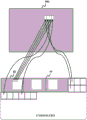
FIG. 4 illustrates a packed frame according to an embodiment;
FIG. 5A illustrates a packed frame according to an embodiment;
FIG. 5B illustrates a packed frame according to an embodiment;
FIG. 6 illustrates a packaging method according to an embodiment;
FIG. 7 illustrates a packaging method according to an embodiment;
FIG. 8 illustrates an encoding method according to an embodiment;
FIG. 9 is a block diagram of a decoder according to an embodiment;
fig. 10 illustrates a decoding method performed by the decoder of fig. 9; and is also provided with
Fig. 11 illustrates a reconstruction method according to an embodiment.
Detailed Description
The present invention will be described with reference to the accompanying drawings.
It should be understood that the detailed description and specific examples, while indicating exemplary embodiments of the apparatus, system, and method, are intended for purposes of illustration only and are not intended to limit the scope of the invention. These and other features, aspects, and advantages of the apparatus, system, and method of the present invention will become better understood from the following description, claims, and accompanying drawings. It should be understood that the figures are merely schematic and are not drawn to scale. It should also be understood that the same reference numerals are used throughout the drawings to refer to the same or like parts.
Fig. 1 is a block diagram of an encoder 100 according to an embodiment. The encoder 100 comprises an input 110, the input 110 being configured to obtain two or more block segmentation masks 12 and block image data 13. The input 100 is connected to a packing unit 120, the packing unit 120 being configured to generate a packed frame 40. The packetizing unit 120 is connected to a video encoder 130, the video encoder 130 being configured to encode the packetized frames 40 into the at least one bitstream 16.
The method performed by the encoder 100 will now be described with reference to fig. 2, 3, 4 and 6. Fig. 2 is a flow chart illustrating the method. In the embodiment described in detail below, three views 10 of a scene have been captured. Fig. 3A illustrates one of the views 10 of the scene. View 10 is uniformly divided into pixel blocks 30. Each of the other views (not shown) is also uniformly divided into pixel blocks. In this example, the pixel blocks 30 in view 10 are all the same size. Each view 10 contains a foreground region and a background region. As is common in the art, a green screen can be used as a background. An example of this is view 10 containing objects placed in front of the green screen. The use of a green screen as a background allows each view 10 to be segmented by chromakeying. Pixels matching the color of the background screen (green in this case) are identified as background pixels.
Fig. 3B illustrates an enlarged view of the block segmentation mask 12 for the view 10 of fig. 3A. Chromakeying has been used to identify foreground regions (referred to herein as regions of interest 31) and background regions. The block segmentation mask 12 is a map of the view 10 indicating which pixel blocks 30 in the view 10 belong to the region of interest 31. Each pixel block 30 in view 10 is represented by a pixel in the block segmentation mask 12 such that the block segmentation mask 12 becomes a low resolution segmentation mask for view 10.
The block segmentation mask 12 indicates whether the pixel block 30 in the view 10 belongs to the region of interest 31 by setting the pixel value of each pixel in the block segmentation mask 12 to a first value or a second value. In the case of segmentation by chromakeying, if a block contains at least one foreground pixel (i.e., at least one pixel of a color other than green), then it may be determined that the block belongs to the region of interest.
In fig. 3B, the pixel values in the block division mask are luminance values. The bright areas 32 of the block segmentation mask 12 indicate the pixel blocks 30 belonging to the region of interest 31 in the view 10. The dark areas 33 of the block segmentation mask 12 indicate pixel blocks 30 in the view 10 that do not belong to the region of interest 31. Fig. 3C illustrates the block image data 13 of view 10 of fig. 3A, as indicated by the block segmentation mask 12 of fig. 3B. The block image data 13 only comprise blocks 30 of pixels belonging to a region of interest 31.
Reference is now made to the flow chart of fig. 2. In step 11, the input 110 obtains a respective block segmentation mask 12 and block image data 13 for each of the views 10. In this example, chroma keying is used to create block segmentation mask 12 and block image data 13. The block division mask 12 and the block image data 13 are transferred to the packing unit 120.
In step 14, the packing unit 120 generates a packed frame 40 containing the block segmentation mask 12 and the block image data 13. Fig. 4 illustrates a packed frame 40. The packing unit 120 continuously packs the block division mask 12 in the first portion 41 of the packed frame 40. The first portion 41 of the packed frame 40 is the first portion to be encoded and subsequently decoded.
The packing unit 120 packs the block image data 13 into the second portion 42 of the packed frame 40. The block image data 13 is also continuously packed, leaving no space between the pixel blocks 30 or between the pixel blocks 30 and the block segmentation mask 12.
Other possible configurations of the packed frame are shown in fig. 5 and will be explained later below.
A packing method for generating the packed frame 40 shown in fig. 4 will now be explained with reference to fig. 6. The block segmentation masks 60, 61 and 62 indicate the respective regions of interest in the first view 600, the second view 610 and the third view 620.
First, the block segmentation masks 60, 61, 62 are packed in a row in a first portion of the packed frame 40. The first block segmentation mask 60 is packed in the leftmost position in the row. The second block division mask 61 is packed next to the first block division mask 60, and the third block division mask 62 is packed next to the second block division mask 61. The block segmentation masks 60, 61, 62 define a sequence in the order from left to right in the rows.
Next, the block image data from each of the three views 600, 610, 620 is packed into a second portion of the packed frame 40 by block interleaving. The packed frame 40 is packed in raster scan order with blocks of pixels. First, the packing unit 120 packs a first pixel block from the first view 600 into the packed frame 40. The packing unit 120 then packs the first pixel block from the second view 610 into the packed frame 40. The packing unit 120 then packs the first pixel block from the third view 620 into the packed frame 40. The loop then repeats, packing the second block of pixels from the first view 600, and so on, until there are not enough pixels from each view to continue the sequence. In this way, pixel blocks in the packed frame 40 are interleaved such that no pixel block immediately precedes or follows another pixel block from the same view unless there are no more sufficient pixel blocks to maintain the interleaving. The sequence of pixel blocks in the packed frame 40 is the same as the sequence defined by the order of the block segmentation masks 60, 61, 62 in the packed frame.
In the same manner as the block image data is packed into the packed frame 40 in raster scan order, the pixel blocks from views 600, 610, 620 are selected for packing in raster scan order, as shown in FIG. 6. A block of pixels is selected from each view 600, 610, 620 for packing in rows from top to bottom of the view 600, 610, 620. Fig. 6 shows that the top-left-most pixel block from view 600 is first packed from the view because it is the first block in the region of interest according to the raster scan order. The next block packed from view 600 is the block immediately to the right of the first block, the second block, according to the raster scan order.
Fig. 7 illustrates an alternative method of packing pixel blocks, referred to as a line interleaving method, which will be explained later below.
After packetization, in step 14, the packetized frame 40 is transmitted to the video encoder 130. Video encoder 130 encodes packetized frame 40 into bitstream 16. Encoding the packed frame includes compressing 15 the packed frame. Compressing 15 the packetized frames 40 reduces the amount of data that must be encoded into the bitstream 16 and transmitted. In this example, the compression 15 is done in a lossy manner. Standard video compression codecs may be used. In this example, the High Efficiency Video Coding (HEVC) compression standard is used.
Compressing 15 the packed frame 40 can reduce the amount of data to be encoded and transmitted, particularly because of the manner in which the packed frame 40 has been packed. In case the region of interest 31 in the respective view 10 contains similar visual content (most likely the multiview images or videos of the scene also contain similar visual content), the block image data 13 from each view 10 may be similar in visual content. More specifically, due to the block interleaved packing method, adjacent pixel blocks in the packed frame may be those corresponding to similar portions of the region of interest as seen from different views. These pixel blocks may have the greatest similarity in visual content. Existing video compression algorithms (e.g., HEVC) are able to exploit this similarity (redundancy). In this manner, by using block interleaving or line interleaving, and using video compression algorithms to compress the packed frames, embodiments of the present invention can reduce the amount of data that needs to be transmitted while utilizing existing video compression software and/or hardware.
Additional steps that can be performed by the encoder in some embodiments are shown in fig. 8 and will be explained later below.
Fig. 9 is a block diagram of a decoder 200 according to an embodiment. The decoder 200 includes an input 210 configured to receive the bit stream 16. The input 210 is connected to a video decoder 220, the video decoder 220 being configured to decode the bitstream 16. The video decoder 220 is connected to a reconstruction unit 230, the reconstruction unit 230 being configured to reconstruct one or more views 93 of the scene. It is assumed that the bit stream 16 received by the decoder 200 is generated by the encoder 100 in the above-described embodiment.
The method performed by the decoder 200 will now be described with reference to fig. 10. In step 90, the input 210 receives the bit stream 16. The bitstream 16 includes a packetized frame 40. The bitstream 16 is transferred to the video decoder 220 and in step 91 the bitstream 16 is decoded in the video decoder 220. Decoding includes decompressing and retrieving the packed frames 40 (using HEVC). After decoding, the packed frame is transferred to the reconstruction unit 230.
In step 92, the reconstruction unit 230 reconstructs three views 93 of the scene. For simplicity, the reconstruction will first be explained with reference to reconstructing only the first view 690. The reconstruction method shown in fig. 11 includes creating a blank first reconstructed view 690. The reconstruction unit 230 inserts blocks of pixels of the first view into the first reconstructed view 690 at foreground locations indicated by the block segmentation mask 60 of the first view.
The block segmentation mask 60 acts as a map indicating the locations (illustrated by the straight arrows) of the foreground blocks in the reconstructed view 690. Both the encoder and decoder scan the block segmentation mask and the block image data using the same predefined scan order. When the decoder finds the first foreground pixel of the block segmentation mask, it inserts the first decoded pixel block at the location indicated by the pixel of the block segmentation mask (illustrated by the curved arrow) in the reconstructed view 690. When it finds the next foreground pixel of the block segmentation mask 60, it inserts the next decoded pixel block for that view, and so on, until all foreground pixel blocks for that view have been arranged in their correct positions in the reconstructed view 690.
The method is equally applicable to reconstructing all views 93, as opposed to the packing process performed at the encoder.
The decoder 200 does not need any additional metadata to know where to find the relevant pixel block and where to locate the relevant pixel block. Instead, the sequence of block segmentation masks 12 and pixel blocks 30 in the packed frame is used as implicit metadata, which indicates to the decoder 200 which block segmentation mask 12 is associated with which pixel blocks. Avoiding the need to include additional metadata with the packed frame 40 can help reduce the amount of data that must be encoded. And reconstruction using block segmentation maps is relatively simple to implement-it does not involve complex or time-consuming operations that may cause significant additional delays.
The foreground blocks (i.e., the block image data of the region of interest) may be superimposed by the decoder on any desired background (e.g., computer graphics background) or images or video from different video streams. In some embodiments, multiple reconstructed views 93 may be used to create a new virtual view having a different point of view than any view originally captured by the camera.
Possible alternative configurations of the packed frame 40 as shown in fig. 5A and 5B will now be discussed. Fig. 5A illustrates a packed frame 40 having a third portion 50 in addition to the first and second portions (not shown). The third portion is at the bottom of the packed frame and is the last portion of the frame to be encoded and decoded. The third portion 50 comprises block depth data 51 for two or more views 10. The block depth data 51 is continuously packed in the packed frame 40. The block depth data 51 may be included in the at least one packed frame 40 at a lower spatial resolution than the block image data 13. For example, the block depth data 51 may be provided in smaller blocks and/or a reduced number of blocks, as the human visual system may be less sensitive to depth errors than to errors of the image data.
Fig. 5B illustrates another packed frame 40 having a fourth portion 52 in addition to the first, second, and third portions (not shown). The fourth portion 52 includes block transparency data 53 of two or more views 10. The block transparency data 53 is continuously packed in the fourth section 52. The transparency data can be determined during segmentation of two or more views and stored in the alpha channel 10. The pixel block at the boundary between the region of interest 31 and the background will likely contain both some (green) background pixels and some foreground pixels (non-green). The block transparency data for a block of pixels identifies the transparency level of the pixel for each pixel in the block. In the case of chromakeying, this can be determined by its green degree, or by any other suitable pixel-level division. During reconstruction, the transparent pixels can be regarded as background pixels. This can help prevent green (background) pixels incorporated in the block image data of the region of interest 31 from appearing as green halos around the object in the reconstructed image 93. Partially transparent pixels (pixels containing some green but not all green) can have their color values averaged by alpha blending. If transparency data 53 is not included in the packed frame, decoder 200 itself can, in some embodiments, perform chroma keying on the pixel block to determine the transparency data. That is, during reconstruction of the view 93, the decoder 200 is able to examine the green pixels of each pixel block 31 (in particular the peripheral blocks) in order to determine the block transparency data of the reconstructed view 93.
In case the packed frame comprises block depth data 51 or block transparency data 53, the block depth and block transparency data can be packed into the third and fourth parts of the packed frame in the same manner as the block image data is packed into the second part of the packed frame. This means that when the decoder is scanning the packed frame 40 and reconstructing the view 93, it can apply the block depth/ transparency data 51, 53 to the reconstructed view using the same inverse block interleaving method as used to generate the reconstructed view 93.
In some embodiments, the block interleaving method described with reference to fig. 6 can be modified to interleave multiple blocks from each view-e.g., two, three, or more blocks at a time are taken as interleaving units.
Fig. 7 shows an example of a packing method based on row interleaving. The row interleaving operation is similar to block interleaving except that instead of packing pixel blocks from each view at a time, the packing unit 120 packs rows of blocks from each view 700, 710, 720. In some embodiments, this principle is further extended by: all blocks of pixels 30 from the first view 10 are packed consecutively, followed by all blocks 30 from the second view 10, and so on for all views 10. The decoder 200 will always reconstruct the view 93 using the inverse of the process used to pack the packed frame 40.
In case it is desired to decode and reconstruct only a subset of the views 10, the row interleaving may be more advantageous than the block interleaving. With line interleaving, it is more likely that the prediction of a block of pixels 30 (at the decoder) will be based on another block of pixels 30 from the same view 10, because compression algorithms often predict based on neighboring blocks, and the entire line of blocks 30 are packed into one contiguous group. This can help avoid the need to decode pixel blocks 30 from additional views 10 when it is desired to decode a given view 10. In the same way, it may be advantageous to pack the packed frame 40 with all pixel blocks 30 placed consecutively from the first view 10, followed by all blocks 30 from the second view 10, and so on for all views 10.
An embodiment of the encoding method shown in fig. 8 will now be explained. Fig. 8 is a flowchart illustrating an encoding method including quantization and compression. Steps 11, 14 and 15 are substantially identical to the corresponding steps in the embodiment of fig. 2 described above.
In step 11, the encoder 100 obtains a block segmentation mask 12 and block image data 13 from two or more views 10 of the scene.
In step 80, the encoder 100 selects a plurality of quantization levels for the block segmentation mask 12. It may be beneficial to quantize the block segmentation mask 12 in order to reduce the amount of data that needs to be transmitted. By way of example, a block segmentation mask 12 that uses luminance values as pixel values should be considered. The first value and the second value can be used to distinguish foreground from background-this can be achieved, for example, by setting all foreground pixels to 255 and all background pixels to 0. Encoding the values 0 and 255 would require 8 bits. In order to reduce the amount of data, the pixel values can be quantized 81 to a smaller number of levels. Instead of using 0 and 255 as the first and second values, 0 and 127 may be used, which for example only requires 7 bits to represent. In the most extreme reduction, each pixel can have a luminance value of 0 or 1 represented by only a single bit.
In step 81, the selected quantization parameter is applied to the block segmentation mask 12. In step 14, the packetizing unit 120 generates the packetized frame 40. In step 82, the encoder selects a figure of merit for video compression. The higher the figure of merit, the less data is lost due to lossy compression.
The packed frames are then encoded into a bitstream 16, the encoding comprising compressing 15 the packed frames using an HEVC codec (with a selected figure of merit). Preferably, the decoder 200 is able to accurately reconstruct the block segmentation mask 12 from the compressed packed frames 40, otherwise the decoder 200 cannot accurately reconstruct the view 93. When selecting quantization levels for the block segmentation mask 12, it may be useful to maintain a certain unused level between the first pixel value and the second pixel value. This can help to make the method robust to small deviations in pixel values that may be introduced by lossy video compression.
In order to ensure that the decoder 200 can accurately reconstruct the block segmentation mask 12, the block segmentation mask 12 must be compressed either by lossless compression or by lossy compression with a minimum figure of merit. For example, binary segmentation masks using values 0 and 1 may be compressed by lossless compression or lossy compression with some minimum quality so that no pixels change values. Alternatively, the segmentation mask using values 0 and 255 may be quantized and compressed by lossy compression. Lossy compression can allow values to deviate from their original level as long as quantization is robust to these deviations, so that there is no reconstruction error. There are various ways to ensure this. In one example, the quantization and quality factor parameters may be selected such that the likelihood of error is low or zero over a large training dataset of views. Alternatively, the encoder can optimize parameters online for a given set of views being encoded. To this end, the encoder 100 can include a local decoder 200, the local decoder 200 decoding the packed frame 40 and reconstructing the block segmentation mask 12 prior to transmitting the bitstream 16. The encoder 100 can check whether an accurate reconstruction has occurred by comparing the decoded block segmentation mask from the local decoder with the original block segmentation mask. The encoder 100 can iteratively quantize the block segmentation mask 12; the packed frame 40 is generated, compressed and encoded, the packed frame 40 is decoded, and the reconstructed block segmentation mask is compared to the original block segmentation mask, changing the quantization and/or compression conditions each time, in order to achieve an accurately reconstructed block segmentation mask with a minimum amount of data. The optimal solution can then be applied to the packed frames 40 and the resulting bit stream 16 transmitted.
The encoding and decoding methods of fig. 2, 8 and 10, and the encoder 100 and decoder 200 of fig. 1 and 9, may be implemented in hardware or software or a mixture of both (e.g., as firmware running on a hardware device). To the extent that embodiments are implemented in part or in whole in software, the functional steps shown in the process flow diagrams may be performed by a suitably programmed physical computing device, such as one or more Central Processing Units (CPUs) or Graphics Processing Units (GPUs). Each process (and its individual constituent steps as shown in the flowcharts) may be performed by the same or different computing devices. According to an embodiment, a computer readable storage medium stores a computer program comprising computer program code configured to cause one or more physical computing devices to perform the encoding or decoding method as described above when the program is run on the one or more physical computing devices.
Various modifications to the examples described above are possible. For example, in the above example, the block partition map is provided to the encoder. In some embodiments, the encoder may include a segmentation unit configured to receive the view 10 and configured to generate the block segmentation mask 12 using chroma keying (or another segmentation algorithm).
In some embodiments, the first pixel value and the second pixel value used in the block segmentation mask 12 may be a chrominance value, a depth value, or a transparency value. In case the block segmentation mask 12 comprises two regions of interest, a first pixel value and a second pixel value can be used to indicate the first region of interest and the second region of interest, respectively, and a third pixel value can be used to indicate the background region. For example, a value of 0 may represent a background, and values 128 and 255 may represent a first region of interest and a second region of interest (e.g., foreground object). Widely spaced values like these may be suitable for lossy compression. Alternatively, the values 1 and 2 may be used for the region of interest, while the value 0 is used for the background. Adjacent values like these may be suitable for lossless compression, wherein there is no risk of introducing a bias in the values.
In some embodiments, the packetizing unit 120 may generate two or more packetized frames. The first packet frame may include two or more block segmentation masks 12. The second packed frame may include block image data 13. Two or more packetized frames are transmitted to video encoder 130. The video encoder 130 may encode a first bitstream including the first packetized frame and a second bitstream including the second packetized frame. The compression of the first bit stream may be lossless and the compression of the second bit stream may be lossy.
It is not necessary that the pixel blocks be the same size in all views. In some embodiments, the pixel blocks of some or all views may be different sizes. Compression and decompression of the packetized frames can be accomplished using any suitable algorithm known in the art (e.g., h.264 or a range of MPEG codecs).
In some embodiments, the block segmentation mask 12 and the block image data 13 need not be packed consecutively. For example, the block segmentation mask of the first view may be followed by block image data of the first view, the block image data of the first view may be followed by the block segmentation mask of the second view and the block image data of the second view, and so on for all views.
Storage media may include volatile and nonvolatile computer memory such as RAM, PROM, EPROM and EEPROM. Various storage media may be fixed or removable within a computing device such that one or more programs stored thereon are loaded into a processor.
Variations to the disclosed embodiments can be understood and effected by those skilled in the art in practicing the claimed invention, from a study of the drawings, the disclosure, and the appended claims. In the claims, the word "comprising" does not exclude other elements or steps, and the word "a" or "an" does not exclude a plurality. A single processor or other unit may fulfill the functions of several items recited in the claims. Although certain measures are recited in mutually different dependent claims, this does not indicate that a combination of these measures cannot be used to advantage. If a computer program is discussed above, it may be stored/distributed on a suitable medium, such as an optical storage medium or a solid-state medium supplied together with or as part of other hardware, but may also be distributed in other forms, such as via the internet or other wired or wireless telecommunication systems. If the term "adapted" is used in the claims or specification, it should be noted that the term "adapted" is intended to be equivalent to the term "configured to". Any reference signs in the claims shall not be construed as limiting the scope.
Claims (15)
1. A method of encoding image or video data comprising two or more views (10) of a scene, the method comprising:
obtaining (11) for each of the two or more views a respective block segmentation mask (12) of the view and block image data (13) of the view;
generating (14) at least one packed frame (40) of the two or more block segmentation masks and the block image data comprising the two or more views; and is also provided with
Encoding (15) said at least one packetized frame into at least one bitstream (16),
wherein each view is divided into pixel blocks (30),
wherein the block segmentation mask indicates which pixel blocks belong to a region of interest (31) in the view,
wherein the region of interest comprises only a portion of the view,
wherein the block image data consists only of the pixel blocks belonging to the region of interest.
2. The method of claim 1, wherein the at least one packed frame comprises one packed frame having a first continuous portion (41) and a second continuous portion (42),
wherein the first continuous portion comprises the block segmentation mask of the two or more views; and is also provided with
Wherein the second continuous portion includes the block image data of the two or more views.
3. The method of claim 1 or 2, wherein within a view, the blocks of pixels in the block image data of the view are all the same size,
optionally, wherein the pixel blocks are the same size in the block image data of all views.
4. The method of any of the preceding claims, wherein the block image data of the respective different views is packed in the at least one packed frame in a block interleaved arrangement, wherein a first block of pixels of a first view is followed by a first block of pixels of a second view.
5. A method according to any of claims 1-3, wherein the block image data of the respective different views are packed in the at least one packed frame in a row interleaved arrangement, wherein the pixel block of the first row of the first view is followed by the pixel block of the first row of the second view.
6. The method according to any of the preceding claims, wherein encoding the at least one packetized frame into the at least one bitstream comprises using a video compression algorithm, optionally using a standard video compression algorithm, e.g. h.264 or HEVC.
7. The method of claim 6, comprising:
-selecting (82) a figure of merit of the video compression algorithm such that at least the block segmentation mask can be reconstructed from the at least one bitstream without error; and/or
The number of quantization levels used in the video compression algorithm is selected (80) such that at least the block segmentation mask can be reconstructed from the at least one bitstream without error.
8. The method according to any of the preceding claims, comprising: -quantizing (81) the block segmentation mask (12) to a first number of quantization levels, and-quantizing (81) the block image data (13) to a second number of quantization levels, wherein the first number is different from the second number.
9. The method of any of the preceding claims, wherein the at least one packed frame comprises a third portion (50), wherein the third portion comprises depth data (51) of the two or more views; and/or
Wherein the at least one packed frame comprises a fourth portion (52), wherein the fourth portion comprises transparency data (53) of the two or more views.
10. A method of decoding image or video data comprising two or more views of a scene, the method comprising:
Receiving (90) at least one bitstream having encoded therein at least one packed frame, said packed frame containing, for each of said two or more views, a respective block segmentation mask for said view and block image data for said view,
wherein each view is divided into pixel blocks,
wherein for each view, the block image data consists only of the pixel blocks belonging to a region of interest in the view, and the block segmentation mask indicates the locations of the pixel blocks belonging to the region of interest in the view,
wherein the region of interest comprises only a portion of the view,
the method further comprises the steps of:
decoding (91) the at least one bitstream to obtain the at least one packetized frame; and is also provided with
-reconstructing (92) at least one of the two or more views (93) by arranging the block image data of the at least one view according to the positions indicated by the respective block segmentation mask for the at least one view.
11. The method according to any of the preceding claims, for use in live multiview video.
12. A computer program comprising computer program code configured to cause one or more physical computing devices to perform all the steps of the method according to any one of the preceding claims when the computer program is run on the one or more physical computing devices.
13. An encoder (100) configured to encode image or video data comprising two or more views of a scene, the encoder comprising:
an input (110) configured to obtain (11) for each of the two or more views a respective block segmentation mask (12) of the view and block image data (13) of the view,
wherein each view is divided into pixel blocks,
wherein the block segmentation mask indicates which pixel blocks belong to a region of interest in the view,
wherein the region of interest comprises only a portion of the view,
wherein the block image data consists only of the pixel blocks belonging to the region of interest;
a packaging unit (120) configured to generate (14) at least one packaging frame containing the two or more block segmentation masks of the two or more views and the block image data; and
a video encoder (130) configured to encode (15) the at least one packetized frame into at least one bitstream.
14. A decoder (200) configured to decode image or video data comprising two or more views of a scene, the decoder comprising:
An input (210) configured to receive (90) at least one bitstream having encoded therein at least one packed frame, the packed frame containing, for each of the two or more views, a respective block segmentation mask for the view and block image data for the view,
wherein each view is divided into pixel blocks,
wherein for each view, the block image data consists only of the pixel blocks belonging to a region of interest in the view, and the block segmentation mask indicates the locations of the pixel blocks belonging to the region of interest in the view,
wherein the region of interest comprises only a portion of the view,
a video decoder (220) configured to decode (91) the at least one bitstream to obtain the at least one packetized frame; and
a reconstruction unit (230) configured to reconstruct (92) at least one of the two or more views (93) by arranging the block image data of the at least one view according to the positions indicated by the respective block segmentation masks for the at least one view.
15. At least one bitstream in which image or video data comprising two or more views of a scene has been encoded, the at least one bitstream comprising:
At least one packed frame containing, for each of the two or more views, a respective block segmentation mask for the view and block image data for the view,
wherein each view is divided into pixel blocks,
wherein for each view, the block image data consists only of the pixel blocks belonging to a region of interest in the view, and the block segmentation mask indicates the locations of the pixel blocks belonging to the region of interest in the view,
wherein the region of interest comprises only a portion of the view.
Applications Claiming Priority (3)
| Application Number | Priority Date | Filing Date | Title |
|---|---|---|---|
| EP20199751.7 | 2020-10-02 | ||
| EP20199751.7A EP3979644A1 (en) | 2020-10-02 | 2020-10-02 | A method and apparatus for encoding and decoding one or more views of a scene |
| PCT/EP2021/076447 WO2022069388A1 (en) | 2020-10-02 | 2021-09-27 | A method and apparatus for encoding and decoding one or more views of a scene |
Publications (1)
| Publication Number | Publication Date |
|---|---|
| CN116250238A true CN116250238A (en) | 2023-06-09 |
Family
ID=72744581
Family Applications (1)
| Application Number | Title | Priority Date | Filing Date |
|---|---|---|---|
| CN202180067571.5A Pending CN116250238A (en) | 2020-10-02 | 2021-09-27 | Method and apparatus for encoding and decoding one or more views of a scene |
Country Status (9)
| Country | Link |
|---|---|
| US (1) | US20230370600A1 (en) |
| EP (2) | EP3979644A1 (en) |
| JP (1) | JP2023542860A (en) |
| KR (1) | KR20230080447A (en) |
| CN (1) | CN116250238A (en) |
| BR (1) | BR112023005833A2 (en) |
| CA (1) | CA3214970A1 (en) |
| TW (1) | TW202220447A (en) |
| WO (1) | WO2022069388A1 (en) |
Families Citing this family (2)
| Publication number | Priority date | Publication date | Assignee | Title |
|---|---|---|---|---|
| FR3137240A1 (en) * | 2022-06-22 | 2023-12-29 | Orange | Method for segmenting a plurality of data, coding method, decoding method, corresponding devices, systems and computer program |
| CN116248895B (en) * | 2023-05-06 | 2023-07-21 | 上海扬谷网络科技有限公司 | Video cloud transcoding method and system for virtual reality panorama roaming |
Family Cites Families (7)
| Publication number | Priority date | Publication date | Assignee | Title |
|---|---|---|---|---|
| US9215445B2 (en) * | 2010-01-29 | 2015-12-15 | Thomson Licensing | Block-based interleaving |
| JP7310816B2 (en) * | 2018-07-06 | 2023-07-19 | ソニーグループ株式会社 | Information processing device, information processing method, and program |
| US11138762B2 (en) * | 2018-07-11 | 2021-10-05 | Samsung Electronics Co., Ltd. | Visual quality of video based point cloud compression using one or more additional patches |
| WO2020071703A1 (en) * | 2018-10-01 | 2020-04-09 | 엘지전자 주식회사 | Point cloud data transmission apparatus, point cloud data transmission method, point cloud data reception apparatus, and/or point cloud data reception method |
| EP3672251A1 (en) * | 2018-12-20 | 2020-06-24 | Koninklijke KPN N.V. | Processing video data for a video player apparatus |
| WO2020146571A1 (en) * | 2019-01-09 | 2020-07-16 | Tencent America LLC | Method and apparatus for dynamic point cloud partition packing |
| US11159811B2 (en) * | 2019-03-15 | 2021-10-26 | Tencent America LLC | Partitioning of coded point cloud data |
-
2020
- 2020-10-02 EP EP20199751.7A patent/EP3979644A1/en not_active Withdrawn
-
2021
- 2021-09-27 JP JP2023516067A patent/JP2023542860A/en active Pending
- 2021-09-27 WO PCT/EP2021/076447 patent/WO2022069388A1/en unknown
- 2021-09-27 BR BR112023005833A patent/BR112023005833A2/en unknown
- 2021-09-27 KR KR1020237014578A patent/KR20230080447A/en unknown
- 2021-09-27 CA CA3214970A patent/CA3214970A1/en active Pending
- 2021-09-27 CN CN202180067571.5A patent/CN116250238A/en active Pending
- 2021-09-27 US US18/029,397 patent/US20230370600A1/en active Pending
- 2021-09-27 EP EP21783493.6A patent/EP4222958A1/en active Pending
- 2021-10-01 TW TW110136713A patent/TW202220447A/en unknown
Also Published As
| Publication number | Publication date |
|---|---|
| CA3214970A1 (en) | 2022-04-07 |
| KR20230080447A (en) | 2023-06-07 |
| TW202220447A (en) | 2022-05-16 |
| EP3979644A1 (en) | 2022-04-06 |
| WO2022069388A1 (en) | 2022-04-07 |
| EP4222958A1 (en) | 2023-08-09 |
| BR112023005833A2 (en) | 2023-05-02 |
| JP2023542860A (en) | 2023-10-12 |
| US20230370600A1 (en) | 2023-11-16 |
Similar Documents
| Publication | Publication Date | Title |
|---|---|---|
| US11272181B2 (en) | Decomposition of residual data during signal encoding, decoding and reconstruction in a tiered hierarchy | |
| US11508094B2 (en) | Point cloud compression | |
| US20210005006A1 (en) | Apparatus for transmitting point cloud data, a method for transmitting point cloud data, an apparatus for receiving point cloud data and a method for receiving point cloud data | |
| KR101915037B1 (en) | Method and Apparatus for Generating Video Bit Stream for Streaming High Resolution Video | |
| US10027982B2 (en) | Segmented-block coding | |
| JP4895400B2 (en) | Improved compression in the representation of non-frame edge blocks of image frames | |
| CN113170237B (en) | Video encoding and decoding method and apparatus | |
| US20230370600A1 (en) | A method and apparatus for encoding and decoding one or more views of a scene | |
| US20220038721A1 (en) | Cross-component quantization in video coding | |
| CN110022481B (en) | Decoding and generating methods and devices of video code stream, storage medium and electronic device | |
| EP3111642B1 (en) | Method and apparatus of single sample mode for video coding | |
| KR20160072038A (en) | Video data processing system | |
| EP4221211A1 (en) | Ai encoding apparatus and method and ai decoding apparatus and method for region of object of interest in image | |
| CN115804096A (en) | Point cloud data transmitting device, point cloud data transmitting method, point cloud data receiving device, and point cloud data receiving method | |
| WO2020175908A1 (en) | Method and device for partitioning picture on basis of signaled information | |
| JP2022523440A (en) | Null tile coding in video coding | |
| EP4199516A1 (en) | Reduction of redundant data in immersive video coding | |
| US20230262262A1 (en) | Packing of views for image or video coding | |
| US20230419557A1 (en) | Point cloud data transmission device, point cloud data transmission method, point cloud data reception device, and point cloud data reception method | |
| KR101268588B1 (en) | Apparatus and method for lossless image compression |
Legal Events
| Date | Code | Title | Description |
|---|---|---|---|
| PB01 | Publication | ||
| PB01 | Publication | ||
| SE01 | Entry into force of request for substantive examination | ||
| SE01 | Entry into force of request for substantive examination |