CN116231046A - Secondary battery - Google Patents
Secondary battery Download PDFInfo
- Publication number
- CN116231046A CN116231046A CN202211265582.7A CN202211265582A CN116231046A CN 116231046 A CN116231046 A CN 116231046A CN 202211265582 A CN202211265582 A CN 202211265582A CN 116231046 A CN116231046 A CN 116231046A
- Authority
- CN
- China
- Prior art keywords
- resin
- cylindrical portion
- secondary battery
- disposed
- electrode terminal
- Prior art date
- Legal status (The legal status is an assumption and is not a legal conclusion. Google has not performed a legal analysis and makes no representation as to the accuracy of the status listed.)
- Pending
Links
- 229920005989 resin Polymers 0.000 claims abstract description 137
- 239000011347 resin Substances 0.000 claims abstract description 137
- 238000010248 power generation Methods 0.000 claims abstract description 39
- 229910052751 metal Inorganic materials 0.000 claims description 79
- 239000002184 metal Substances 0.000 claims description 79
- XLYOFNOQVPJJNP-UHFFFAOYSA-N water Chemical compound O XLYOFNOQVPJJNP-UHFFFAOYSA-N 0.000 claims description 33
- 230000004888 barrier function Effects 0.000 claims description 24
- 239000005001 laminate film Substances 0.000 claims description 12
- 238000009413 insulation Methods 0.000 claims description 10
- 238000007789 sealing Methods 0.000 description 36
- 239000011888 foil Substances 0.000 description 27
- 239000007784 solid electrolyte Substances 0.000 description 18
- 230000002093 peripheral effect Effects 0.000 description 13
- 239000007774 positive electrode material Substances 0.000 description 13
- 239000000463 material Substances 0.000 description 12
- 239000003792 electrolyte Substances 0.000 description 10
- HBBGRARXTFLTSG-UHFFFAOYSA-N Lithium ion Chemical compound [Li+] HBBGRARXTFLTSG-UHFFFAOYSA-N 0.000 description 9
- 229910001416 lithium ion Inorganic materials 0.000 description 9
- 229910052782 aluminium Inorganic materials 0.000 description 8
- XAGFODPZIPBFFR-UHFFFAOYSA-N aluminium Chemical compound [Al] XAGFODPZIPBFFR-UHFFFAOYSA-N 0.000 description 8
- 238000003466 welding Methods 0.000 description 8
- 239000011230 binding agent Substances 0.000 description 7
- 239000011810 insulating material Substances 0.000 description 7
- WHXSMMKQMYFTQS-UHFFFAOYSA-N Lithium Chemical compound [Li] WHXSMMKQMYFTQS-UHFFFAOYSA-N 0.000 description 6
- -1 Polyethylene Polymers 0.000 description 6
- 238000010586 diagram Methods 0.000 description 6
- 229910052744 lithium Inorganic materials 0.000 description 6
- 239000007773 negative electrode material Substances 0.000 description 6
- 239000004743 Polypropylene Substances 0.000 description 5
- 229920001155 polypropylene Polymers 0.000 description 5
- 239000007787 solid Substances 0.000 description 5
- 238000000034 method Methods 0.000 description 4
- 239000010935 stainless steel Substances 0.000 description 4
- 229910001220 stainless steel Inorganic materials 0.000 description 4
- OKTJSMMVPCPJKN-UHFFFAOYSA-N Carbon Chemical compound [C] OKTJSMMVPCPJKN-UHFFFAOYSA-N 0.000 description 3
- 229910018130 Li 2 S-P 2 S 5 Inorganic materials 0.000 description 3
- 239000005062 Polybutadiene Substances 0.000 description 3
- VYPSYNLAJGMNEJ-UHFFFAOYSA-N Silicium dioxide Chemical compound O=[Si]=O VYPSYNLAJGMNEJ-UHFFFAOYSA-N 0.000 description 3
- 239000006183 anode active material Substances 0.000 description 3
- 239000012752 auxiliary agent Substances 0.000 description 3
- 230000005540 biological transmission Effects 0.000 description 3
- 238000001816 cooling Methods 0.000 description 3
- 230000006866 deterioration Effects 0.000 description 3
- 239000011521 glass Substances 0.000 description 3
- 229910003480 inorganic solid Inorganic materials 0.000 description 3
- 239000007788 liquid Substances 0.000 description 3
- 150000002739 metals Chemical class 0.000 description 3
- 229920002857 polybutadiene Polymers 0.000 description 3
- 239000002203 sulfidic glass Substances 0.000 description 3
- 239000003115 supporting electrolyte Substances 0.000 description 3
- 229910000737 Duralumin Inorganic materials 0.000 description 2
- PXHVJJICTQNCMI-UHFFFAOYSA-N Nickel Chemical compound [Ni] PXHVJJICTQNCMI-UHFFFAOYSA-N 0.000 description 2
- 239000004698 Polyethylene Substances 0.000 description 2
- RTAQQCXQSZGOHL-UHFFFAOYSA-N Titanium Chemical compound [Ti] RTAQQCXQSZGOHL-UHFFFAOYSA-N 0.000 description 2
- 239000000853 adhesive Substances 0.000 description 2
- 230000001070 adhesive effect Effects 0.000 description 2
- 239000003795 chemical substances by application Substances 0.000 description 2
- 239000011248 coating agent Substances 0.000 description 2
- 238000000576 coating method Methods 0.000 description 2
- 238000010276 construction Methods 0.000 description 2
- 238000010227 cup method (microbiological evaluation) Methods 0.000 description 2
- 230000002950 deficient Effects 0.000 description 2
- 230000000694 effects Effects 0.000 description 2
- 230000004927 fusion Effects 0.000 description 2
- 238000007689 inspection Methods 0.000 description 2
- 230000010354 integration Effects 0.000 description 2
- VDVLPSWVDYJFRW-UHFFFAOYSA-N lithium;bis(fluorosulfonyl)azanide Chemical compound [Li+].FS(=O)(=O)[N-]S(F)(=O)=O VDVLPSWVDYJFRW-UHFFFAOYSA-N 0.000 description 2
- 230000033001 locomotion Effects 0.000 description 2
- 238000004519 manufacturing process Methods 0.000 description 2
- 229920000620 organic polymer Polymers 0.000 description 2
- 230000035699 permeability Effects 0.000 description 2
- 229920000573 polyethylene Polymers 0.000 description 2
- 229920000139 polyethylene terephthalate Polymers 0.000 description 2
- 239000005020 polyethylene terephthalate Substances 0.000 description 2
- 239000005518 polymer electrolyte Substances 0.000 description 2
- 239000002904 solvent Substances 0.000 description 2
- 229920005992 thermoplastic resin Polymers 0.000 description 2
- BQCIDUSAKPWEOX-UHFFFAOYSA-N 1,1-Difluoroethene Chemical group FC(F)=C BQCIDUSAKPWEOX-UHFFFAOYSA-N 0.000 description 1
- VXNZUUAINFGPBY-UHFFFAOYSA-N 1-Butene Chemical compound CCC=C VXNZUUAINFGPBY-UHFFFAOYSA-N 0.000 description 1
- 229910005839 GeS 2 Inorganic materials 0.000 description 1
- 229910018133 Li 2 S-SiS 2 Inorganic materials 0.000 description 1
- 229910000733 Li alloy Inorganic materials 0.000 description 1
- 229910013063 LiBF 4 Inorganic materials 0.000 description 1
- 229910010835 LiI-Li2S-P2S5 Inorganic materials 0.000 description 1
- 229910010833 LiI-Li2S-SiS2 Inorganic materials 0.000 description 1
- 229910010842 LiI—Li2S—P2O5 Inorganic materials 0.000 description 1
- 229910010840 LiI—Li2S—P2S5 Inorganic materials 0.000 description 1
- 229910010855 LiI—Li2S—SiS2 Inorganic materials 0.000 description 1
- 229910010847 LiI—Li3PO4-P2S5 Inorganic materials 0.000 description 1
- 229910010864 LiI—Li3PO4—P2S5 Inorganic materials 0.000 description 1
- 229910013870 LiPF 6 Inorganic materials 0.000 description 1
- 239000004677 Nylon Substances 0.000 description 1
- 229910000676 Si alloy Inorganic materials 0.000 description 1
- FKNQFGJONOIPTF-UHFFFAOYSA-N Sodium cation Chemical compound [Na+] FKNQFGJONOIPTF-UHFFFAOYSA-N 0.000 description 1
- HFCVPDYCRZVZDF-UHFFFAOYSA-N [Li+].[Co+2].[Ni+2].[O-][Mn]([O-])(=O)=O Chemical compound [Li+].[Co+2].[Ni+2].[O-][Mn]([O-])(=O)=O HFCVPDYCRZVZDF-UHFFFAOYSA-N 0.000 description 1
- RJEIKIOYHOOKDL-UHFFFAOYSA-N [Li].[La] Chemical compound [Li].[La] RJEIKIOYHOOKDL-UHFFFAOYSA-N 0.000 description 1
- 239000006230 acetylene black Substances 0.000 description 1
- 239000011149 active material Substances 0.000 description 1
- 229940024548 aluminum oxide Drugs 0.000 description 1
- 238000005452 bending Methods 0.000 description 1
- YFRNYWVKHCQRPE-UHFFFAOYSA-N buta-1,3-diene;prop-2-enoic acid Chemical compound C=CC=C.OC(=O)C=C YFRNYWVKHCQRPE-UHFFFAOYSA-N 0.000 description 1
- IAQRGUVFOMOMEM-UHFFFAOYSA-N butene Natural products CC=CC IAQRGUVFOMOMEM-UHFFFAOYSA-N 0.000 description 1
- 229910052799 carbon Inorganic materials 0.000 description 1
- 239000002388 carbon-based active material Substances 0.000 description 1
- 239000003575 carbonaceous material Substances 0.000 description 1
- 150000004649 carbonic acid derivatives Chemical class 0.000 description 1
- 239000006182 cathode active material Substances 0.000 description 1
- 239000002131 composite material Substances 0.000 description 1
- 229910052802 copper Inorganic materials 0.000 description 1
- 238000005520 cutting process Methods 0.000 description 1
- QHGJSLXSVXVKHZ-UHFFFAOYSA-N dilithium;dioxido(dioxo)manganese Chemical compound [Li+].[Li+].[O-][Mn]([O-])(=O)=O QHGJSLXSVXVKHZ-UHFFFAOYSA-N 0.000 description 1
- 239000002270 dispersing agent Substances 0.000 description 1
- 229920001971 elastomer Polymers 0.000 description 1
- 239000008151 electrolyte solution Substances 0.000 description 1
- 238000005516 engineering process Methods 0.000 description 1
- 150000002148 esters Chemical class 0.000 description 1
- 150000002170 ethers Chemical class 0.000 description 1
- 238000004817 gas chromatography Methods 0.000 description 1
- 239000010439 graphite Substances 0.000 description 1
- 229910002804 graphite Inorganic materials 0.000 description 1
- 229910021385 hard carbon Inorganic materials 0.000 description 1
- 230000009545 invasion Effects 0.000 description 1
- 150000002596 lactones Chemical class 0.000 description 1
- 238000010030 laminating Methods 0.000 description 1
- 239000001989 lithium alloy Substances 0.000 description 1
- 229910003473 lithium bis(trifluoromethanesulfonyl)imide Inorganic materials 0.000 description 1
- AMXOYNBUYSYVKV-UHFFFAOYSA-M lithium bromide Inorganic materials [Li+].[Br-] AMXOYNBUYSYVKV-UHFFFAOYSA-M 0.000 description 1
- 150000002642 lithium compounds Chemical class 0.000 description 1
- GQYHUHYESMUTHG-UHFFFAOYSA-N lithium niobate Chemical compound [Li+].[O-][Nb](=O)=O GQYHUHYESMUTHG-UHFFFAOYSA-N 0.000 description 1
- 229910001386 lithium phosphate Inorganic materials 0.000 description 1
- QSZMZKBZAYQGRS-UHFFFAOYSA-N lithium;bis(trifluoromethylsulfonyl)azanide Chemical compound [Li+].FC(F)(F)S(=O)(=O)[N-]S(=O)(=O)C(F)(F)F QSZMZKBZAYQGRS-UHFFFAOYSA-N 0.000 description 1
- 239000007769 metal material Substances 0.000 description 1
- VNWKTOKETHGBQD-UHFFFAOYSA-N methane Chemical compound C VNWKTOKETHGBQD-UHFFFAOYSA-N 0.000 description 1
- 238000000465 moulding Methods 0.000 description 1
- 229910052759 nickel Inorganic materials 0.000 description 1
- 150000002825 nitriles Chemical class 0.000 description 1
- 229920001778 nylon Polymers 0.000 description 1
- 238000004806 packaging method and process Methods 0.000 description 1
- 229920000728 polyester Polymers 0.000 description 1
- 229920000098 polyolefin Polymers 0.000 description 1
- 229920002981 polyvinylidene fluoride Polymers 0.000 description 1
- 239000005060 rubber Substances 0.000 description 1
- 238000004904 shortening Methods 0.000 description 1
- 229910052710 silicon Inorganic materials 0.000 description 1
- 239000000377 silicon dioxide Substances 0.000 description 1
- 235000012239 silicon dioxide Nutrition 0.000 description 1
- 229910052814 silicon oxide Inorganic materials 0.000 description 1
- 239000002409 silicon-based active material Substances 0.000 description 1
- 229910001415 sodium ion Inorganic materials 0.000 description 1
- 229910052596 spinel Inorganic materials 0.000 description 1
- 239000011029 spinel Substances 0.000 description 1
- 150000003457 sulfones Chemical class 0.000 description 1
- 239000002562 thickening agent Substances 0.000 description 1
- AEXDMFVPDVVSQJ-UHFFFAOYSA-N trifluoro(trifluoromethylsulfonyl)methane Chemical group FC(F)(F)S(=O)(=O)C(F)(F)F AEXDMFVPDVVSQJ-UHFFFAOYSA-N 0.000 description 1
- TWQULNDIKKJZPH-UHFFFAOYSA-K trilithium;phosphate Chemical compound [Li+].[Li+].[Li+].[O-]P([O-])([O-])=O TWQULNDIKKJZPH-UHFFFAOYSA-K 0.000 description 1
Images


Classifications
-
- H—ELECTRICITY
- H01—ELECTRIC ELEMENTS
- H01M—PROCESSES OR MEANS, e.g. BATTERIES, FOR THE DIRECT CONVERSION OF CHEMICAL ENERGY INTO ELECTRICAL ENERGY
- H01M50/00—Constructional details or processes of manufacture of the non-active parts of electrochemical cells other than fuel cells, e.g. hybrid cells
- H01M50/10—Primary casings; Jackets or wrappings
- H01M50/183—Sealing members
- H01M50/186—Sealing members characterised by the disposition of the sealing members
- H01M50/188—Sealing members characterised by the disposition of the sealing members the sealing members being arranged between the lid and terminal
-
- H—ELECTRICITY
- H01—ELECTRIC ELEMENTS
- H01M—PROCESSES OR MEANS, e.g. BATTERIES, FOR THE DIRECT CONVERSION OF CHEMICAL ENERGY INTO ELECTRICAL ENERGY
- H01M50/00—Constructional details or processes of manufacture of the non-active parts of electrochemical cells other than fuel cells, e.g. hybrid cells
- H01M50/10—Primary casings; Jackets or wrappings
- H01M50/147—Lids or covers
- H01M50/155—Lids or covers characterised by the material
- H01M50/16—Organic material
-
- H—ELECTRICITY
- H01—ELECTRIC ELEMENTS
- H01M—PROCESSES OR MEANS, e.g. BATTERIES, FOR THE DIRECT CONVERSION OF CHEMICAL ENERGY INTO ELECTRICAL ENERGY
- H01M10/00—Secondary cells; Manufacture thereof
- H01M10/04—Construction or manufacture in general
-
- H—ELECTRICITY
- H01—ELECTRIC ELEMENTS
- H01M—PROCESSES OR MEANS, e.g. BATTERIES, FOR THE DIRECT CONVERSION OF CHEMICAL ENERGY INTO ELECTRICAL ENERGY
- H01M10/00—Secondary cells; Manufacture thereof
- H01M10/04—Construction or manufacture in general
- H01M10/0431—Cells with wound or folded electrodes
-
- H—ELECTRICITY
- H01—ELECTRIC ELEMENTS
- H01M—PROCESSES OR MEANS, e.g. BATTERIES, FOR THE DIRECT CONVERSION OF CHEMICAL ENERGY INTO ELECTRICAL ENERGY
- H01M10/00—Secondary cells; Manufacture thereof
- H01M10/05—Accumulators with non-aqueous electrolyte
- H01M10/052—Li-accumulators
- H01M10/0525—Rocking-chair batteries, i.e. batteries with lithium insertion or intercalation in both electrodes; Lithium-ion batteries
-
- H—ELECTRICITY
- H01—ELECTRIC ELEMENTS
- H01M—PROCESSES OR MEANS, e.g. BATTERIES, FOR THE DIRECT CONVERSION OF CHEMICAL ENERGY INTO ELECTRICAL ENERGY
- H01M50/00—Constructional details or processes of manufacture of the non-active parts of electrochemical cells other than fuel cells, e.g. hybrid cells
- H01M50/10—Primary casings; Jackets or wrappings
- H01M50/102—Primary casings; Jackets or wrappings characterised by their shape or physical structure
- H01M50/103—Primary casings; Jackets or wrappings characterised by their shape or physical structure prismatic or rectangular
-
- H—ELECTRICITY
- H01—ELECTRIC ELEMENTS
- H01M—PROCESSES OR MEANS, e.g. BATTERIES, FOR THE DIRECT CONVERSION OF CHEMICAL ENERGY INTO ELECTRICAL ENERGY
- H01M50/00—Constructional details or processes of manufacture of the non-active parts of electrochemical cells other than fuel cells, e.g. hybrid cells
- H01M50/10—Primary casings; Jackets or wrappings
- H01M50/102—Primary casings; Jackets or wrappings characterised by their shape or physical structure
- H01M50/107—Primary casings; Jackets or wrappings characterised by their shape or physical structure having curved cross-section, e.g. round or elliptic
-
- H—ELECTRICITY
- H01—ELECTRIC ELEMENTS
- H01M—PROCESSES OR MEANS, e.g. BATTERIES, FOR THE DIRECT CONVERSION OF CHEMICAL ENERGY INTO ELECTRICAL ENERGY
- H01M50/00—Constructional details or processes of manufacture of the non-active parts of electrochemical cells other than fuel cells, e.g. hybrid cells
- H01M50/10—Primary casings; Jackets or wrappings
- H01M50/116—Primary casings; Jackets or wrappings characterised by the material
- H01M50/117—Inorganic material
- H01M50/119—Metals
-
- H—ELECTRICITY
- H01—ELECTRIC ELEMENTS
- H01M—PROCESSES OR MEANS, e.g. BATTERIES, FOR THE DIRECT CONVERSION OF CHEMICAL ENERGY INTO ELECTRICAL ENERGY
- H01M50/00—Constructional details or processes of manufacture of the non-active parts of electrochemical cells other than fuel cells, e.g. hybrid cells
- H01M50/10—Primary casings; Jackets or wrappings
- H01M50/116—Primary casings; Jackets or wrappings characterised by the material
- H01M50/121—Organic material
-
- H—ELECTRICITY
- H01—ELECTRIC ELEMENTS
- H01M—PROCESSES OR MEANS, e.g. BATTERIES, FOR THE DIRECT CONVERSION OF CHEMICAL ENERGY INTO ELECTRICAL ENERGY
- H01M50/00—Constructional details or processes of manufacture of the non-active parts of electrochemical cells other than fuel cells, e.g. hybrid cells
- H01M50/10—Primary casings; Jackets or wrappings
- H01M50/116—Primary casings; Jackets or wrappings characterised by the material
- H01M50/124—Primary casings; Jackets or wrappings characterised by the material having a layered structure
-
- H—ELECTRICITY
- H01—ELECTRIC ELEMENTS
- H01M—PROCESSES OR MEANS, e.g. BATTERIES, FOR THE DIRECT CONVERSION OF CHEMICAL ENERGY INTO ELECTRICAL ENERGY
- H01M50/00—Constructional details or processes of manufacture of the non-active parts of electrochemical cells other than fuel cells, e.g. hybrid cells
- H01M50/10—Primary casings; Jackets or wrappings
- H01M50/131—Primary casings; Jackets or wrappings characterised by physical properties, e.g. gas permeability, size or heat resistance
- H01M50/133—Thickness
-
- H—ELECTRICITY
- H01—ELECTRIC ELEMENTS
- H01M—PROCESSES OR MEANS, e.g. BATTERIES, FOR THE DIRECT CONVERSION OF CHEMICAL ENERGY INTO ELECTRICAL ENERGY
- H01M50/00—Constructional details or processes of manufacture of the non-active parts of electrochemical cells other than fuel cells, e.g. hybrid cells
- H01M50/10—Primary casings; Jackets or wrappings
- H01M50/147—Lids or covers
- H01M50/148—Lids or covers characterised by their shape
- H01M50/152—Lids or covers characterised by their shape for cells having curved cross-section, e.g. round or elliptic
-
- H—ELECTRICITY
- H01—ELECTRIC ELEMENTS
- H01M—PROCESSES OR MEANS, e.g. BATTERIES, FOR THE DIRECT CONVERSION OF CHEMICAL ENERGY INTO ELECTRICAL ENERGY
- H01M50/00—Constructional details or processes of manufacture of the non-active parts of electrochemical cells other than fuel cells, e.g. hybrid cells
- H01M50/10—Primary casings; Jackets or wrappings
- H01M50/172—Arrangements of electric connectors penetrating the casing
- H01M50/174—Arrangements of electric connectors penetrating the casing adapted for the shape of the cells
- H01M50/176—Arrangements of electric connectors penetrating the casing adapted for the shape of the cells for prismatic or rectangular cells
-
- H—ELECTRICITY
- H01—ELECTRIC ELEMENTS
- H01M—PROCESSES OR MEANS, e.g. BATTERIES, FOR THE DIRECT CONVERSION OF CHEMICAL ENERGY INTO ELECTRICAL ENERGY
- H01M50/00—Constructional details or processes of manufacture of the non-active parts of electrochemical cells other than fuel cells, e.g. hybrid cells
- H01M50/10—Primary casings; Jackets or wrappings
- H01M50/172—Arrangements of electric connectors penetrating the casing
- H01M50/174—Arrangements of electric connectors penetrating the casing adapted for the shape of the cells
- H01M50/179—Arrangements of electric connectors penetrating the casing adapted for the shape of the cells for cells having curved cross-section, e.g. round or elliptic
-
- H—ELECTRICITY
- H01—ELECTRIC ELEMENTS
- H01M—PROCESSES OR MEANS, e.g. BATTERIES, FOR THE DIRECT CONVERSION OF CHEMICAL ENERGY INTO ELECTRICAL ENERGY
- H01M50/00—Constructional details or processes of manufacture of the non-active parts of electrochemical cells other than fuel cells, e.g. hybrid cells
- H01M50/10—Primary casings; Jackets or wrappings
- H01M50/183—Sealing members
- H01M50/19—Sealing members characterised by the material
- H01M50/193—Organic material
-
- H—ELECTRICITY
- H01—ELECTRIC ELEMENTS
- H01M—PROCESSES OR MEANS, e.g. BATTERIES, FOR THE DIRECT CONVERSION OF CHEMICAL ENERGY INTO ELECTRICAL ENERGY
- H01M50/00—Constructional details or processes of manufacture of the non-active parts of electrochemical cells other than fuel cells, e.g. hybrid cells
- H01M50/50—Current conducting connections for cells or batteries
- H01M50/543—Terminals
- H01M50/547—Terminals characterised by the disposition of the terminals on the cells
- H01M50/55—Terminals characterised by the disposition of the terminals on the cells on the same side of the cell
-
- H—ELECTRICITY
- H01—ELECTRIC ELEMENTS
- H01M—PROCESSES OR MEANS, e.g. BATTERIES, FOR THE DIRECT CONVERSION OF CHEMICAL ENERGY INTO ELECTRICAL ENERGY
- H01M50/00—Constructional details or processes of manufacture of the non-active parts of electrochemical cells other than fuel cells, e.g. hybrid cells
- H01M50/50—Current conducting connections for cells or batteries
- H01M50/543—Terminals
- H01M50/552—Terminals characterised by their shape
- H01M50/553—Terminals adapted for prismatic, pouch or rectangular cells
- H01M50/557—Plate-shaped terminals
-
- H—ELECTRICITY
- H01—ELECTRIC ELEMENTS
- H01M—PROCESSES OR MEANS, e.g. BATTERIES, FOR THE DIRECT CONVERSION OF CHEMICAL ENERGY INTO ELECTRICAL ENERGY
- H01M50/00—Constructional details or processes of manufacture of the non-active parts of electrochemical cells other than fuel cells, e.g. hybrid cells
- H01M50/50—Current conducting connections for cells or batteries
- H01M50/543—Terminals
- H01M50/552—Terminals characterised by their shape
- H01M50/559—Terminals adapted for cells having curved cross-section, e.g. round, elliptic or button cells
-
- H—ELECTRICITY
- H01—ELECTRIC ELEMENTS
- H01M—PROCESSES OR MEANS, e.g. BATTERIES, FOR THE DIRECT CONVERSION OF CHEMICAL ENERGY INTO ELECTRICAL ENERGY
- H01M50/00—Constructional details or processes of manufacture of the non-active parts of electrochemical cells other than fuel cells, e.g. hybrid cells
- H01M50/50—Current conducting connections for cells or batteries
- H01M50/543—Terminals
- H01M50/562—Terminals characterised by the material
-
- Y—GENERAL TAGGING OF NEW TECHNOLOGICAL DEVELOPMENTS; GENERAL TAGGING OF CROSS-SECTIONAL TECHNOLOGIES SPANNING OVER SEVERAL SECTIONS OF THE IPC; TECHNICAL SUBJECTS COVERED BY FORMER USPC CROSS-REFERENCE ART COLLECTIONS [XRACs] AND DIGESTS
- Y02—TECHNOLOGIES OR APPLICATIONS FOR MITIGATION OR ADAPTATION AGAINST CLIMATE CHANGE
- Y02E—REDUCTION OF GREENHOUSE GAS [GHG] EMISSIONS, RELATED TO ENERGY GENERATION, TRANSMISSION OR DISTRIBUTION
- Y02E60/00—Enabling technologies; Technologies with a potential or indirect contribution to GHG emissions mitigation
- Y02E60/10—Energy storage using batteries
Landscapes
- Chemical & Material Sciences (AREA)
- Chemical Kinetics & Catalysis (AREA)
- Electrochemistry (AREA)
- General Chemical & Material Sciences (AREA)
- Engineering & Computer Science (AREA)
- Manufacturing & Machinery (AREA)
- Materials Engineering (AREA)
- Inorganic Chemistry (AREA)
- Sealing Battery Cases Or Jackets (AREA)
- Cell Separators (AREA)
- Secondary Cells (AREA)
Abstract
The present invention relates to a secondary battery capable of improving the structural efficiency. The secondary battery includes a power generation element and an exterior part for housing the power generation element therein, and the exterior part includes: the resin 1 is disposed so as to fill between the cylindrical portion and the inner lid, and the cylindrical portion and the inner lid are integrated with the resin 1.
Description
Technical Field
The present application relates to secondary batteries.
Background
Batteries such as lithium ion secondary batteries are widely used as portable power sources for personal computers, portable terminals, and power sources for driving vehicles. As an example of the battery, a laminate type battery is known. The laminated battery has a structure in which a power generating element is sealed inside a laminated outer package formed by laminating film-like laminated sheets. The laminated battery further includes a sealing region formed by welding edges of the laminated outer package disposed so as to face each other in a state where terminals electrically connected to the power generating elements protrude outward from the inside of the laminated outer package. Thereby, the power generating element is sealed inside the laminated outer package. The laminated battery further includes a sealing region formed by welding laminated sheets in an overlapping manner on the outer side of the power generating element.
Conventionally, miniaturization of battery structures has been studied. For example, patent document 1 discloses a technique of bending a sealing region at an end of a laminated battery to reduce the size.
Prior art literature
Patent literature
Patent document 1: japanese patent laid-open No. 2020-173900
Disclosure of Invention
Problems to be solved by the invention
The technology of patent document 1 can achieve downsizing of the laminated battery, but further improvement in structural efficiency of the secondary battery is desired.
The downsizing of the laminated battery can be achieved by shortening the width (sealing width) of the sealing region sandwiching the electrode terminal, for example, but the sealing width needs to be set to a length exceeding 3mm in general. This is for the following reason. (1) If the sealing width is short, heat welding cannot be performed properly, and sealing failure may occur. (2) Since the laminate package is not high in rigidity, if the seal width is short, the adhesion of the seal area may be peeled off by an external impact, and the adhesion surface may not be maintained. (3) When the terminals are not parallel to the bonding surface of the laminate package during heat sealing, the correction force for obliquely restoring the terminals becomes weak when the sealing width is short, and therefore, the probability of failure in heat sealing due to failure is high. (4) When the sealing width is short at the time of heat sealing, the pressure per unit area applied to the sealing region by the heat sealing head becomes large, and there is a possibility that the metal layer inside the laminate package may bite into the terminal across the insulating layer. If the metal layer bites into the terminal, a short circuit is caused, which is undesirable. For the above reasons, it is difficult to shorten the sealing width and miniaturize the laminated battery.
Accordingly, it is an object of the present disclosure to provide a secondary battery capable of improving the construction efficiency.
Means for solving the problems
As one aspect for solving the above-described problems, the present disclosure provides a secondary battery including a power generation element and an exterior part housing the power generation element therein, the exterior part including: the resin 1 is disposed so as to fill between the cylindrical portion and the inner lid, and the cylindrical portion and the inner lid are integrated with the resin 1.
The secondary battery may be as follows. That is, the secondary battery may further include an electrode terminal connected to the power generating element, the inner lid may include a surface disposed on an opening side of the cylindrical portion, a protruding portion protruding from an entire outer periphery of the surface toward an inner side of the cylindrical portion, and a space surrounded by the protruding portion, at least one of the inner lids may include a through hole in the surface, the electrode terminal may be disposed so as to penetrate the through hole, and the 1 st resin disposed on the inner lid side through which the electrode terminal penetrates may be disposed so as to cover an outer periphery of at least a part of the electrode terminal and to fill in between the through hole and the electrode terminal, and the cylindrical portion, the inner lid, and the electrode terminal may be integrated by the 1 st resin.
The secondary battery may be as follows. That is, the exterior part may have the 2 nd resin filled therein, and the cylindrical part, the inner cover, the electrode terminal, and the power generating element may be integrated with the 2 nd resin. The power generating element may be covered with a resin film having insulation and water vapor barrier properties (water vapor barrier properties).
The cylindrical portion may be as follows. That is, the cylindrical portion may be a cylindrical metal body or a metal laminate film formed into a cylindrical shape. Alternatively, the tubular portion may be formed of 2 metal plates in a U shape that are overlapped upside down, and the ends of the metal plates may be overlapped on the opposite side surfaces of the tubular portion, the tubular portion may have a 3 rd resin disposed so as to cover the side surfaces, and the overlapped ends of the metal plates may be integrated by the 3 rd resin. Alternatively, the tubular portion may be formed of 1 metal plate, and an end portion of the metal plate may be overlapped on one side surface of the tubular portion, the tubular portion may include a 3 rd resin disposed so as to cover the one side surface of the tubular portion, and the overlapped end portions of the metal plates may be integrated by the 3 rd resin.
Effects of the invention
According to the secondary battery of the present disclosure, the construction efficiency can be improved.
Drawings
Fig. 1 is a plan view of a secondary battery 100.
Fig. 2 is a sectional view taken at II-II of fig. 1.
Fig. 3 is a plan view of an example of a secondary battery in which the positive electrode terminal 31 and the negative electrode terminal 32 are arranged so as to protrude from the same surface in the width direction of the exterior part 20.
Fig. 4 (a) is a plan view of the cylindrical portion 21. Fig. 4 (b) is a widthwise cross-sectional view. Fig. 4 (c) is a side view of the cylindrical portion 21 as viewed from the width direction.
Fig. 5 (a) is a cross-sectional view of the vicinity of the opening 21a of the cylindrical portion 21 in which the protruding portion 21b is provided at each end of the surface in the thickness direction. Fig. 5 (b) is a cross-sectional view of the vicinity of the opening 21a of the tubular portion 21 in which the protruding portion 21b is provided.
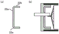
Fig. 6 (a) is a perspective view of the inner cap 22. Fig. 6 (b) is a sectional view taken at b-b of (a). Fig. 6 (c) is a cross-sectional view taken at c-c of (a).
Fig. 7 (a) is a cross-sectional view of the inner cap 22 having a tapered portion (inclined surface portion) 22 e. Fig. 7 (b) shows an example of using the inner cap 22 having the tapered portion 22 e.
Fig. 8 is a diagram comparing a longitudinal cross-sectional view of a conventional laminated battery (a) and a secondary battery 100 (b).
Fig. 9 is a diagram comparing a top view of a conventional laminated battery (a) and a secondary battery 100 (b).
Fig. 10 is a longitudinal sectional view of the secondary battery 101.
Fig. 11 is a longitudinal sectional view of the secondary battery 102.
Fig. 12 is a plan view of the power generating element 10 surrounded by the resin film 13.
Fig. 13 (a) is a plan view of the cylindrical portion 121. Fig. 13 (b) is a cross-sectional view in the width direction of the cylindrical portion 121.
Fig. 14 (a) is a plan view of the cylindrical portion 221. Fig. 14 (b) is a cross-sectional view in the width direction of the cylindrical portion 221.
Fig. 15 is a diagram showing 1 cooling method of a secondary battery using a cylindrical portion 221.
Description of the reference numerals
10. Power generation element
11. 12 pole ear (Pole piece)
13. Resin film
20. Outer part
21. 121, 122 cylindrical portion
21a opening part
21b projection
21c hole
21d hole
22. Inner cap
22a face
22b projection
22c space
22d through hole
22e taper
22f hole
23. 1 st resin
24. Resin 2
30. Electrode terminal
31. Positive electrode terminal
32. Negative electrode terminal
100. 101, 102 secondary battery
121a, 221a metal plate
121b bottom surface
121c projection
121d, 221c 3 rd resin
221b end
Detailed Description
The secondary battery of the present disclosure will be described mainly with reference to the secondary battery 100 as one embodiment.
Fig. 1 shows a top view of the secondary battery 100. Fig. 2 shows a sectional view taken at II-II of fig. 1. In fig. 1 and 2, the longitudinal direction of the secondary battery 100 is denoted by x, the width direction of the secondary battery 100 is denoted by y, and the thickness direction of the secondary battery 100 is denoted by z. These directions are in respectively orthogonal relation.
The secondary battery 100 includes a power generation element 10 and an exterior 20 that accommodates the power generation element 10 therein. The secondary battery 100 includes a positive electrode terminal 31 and a negative electrode terminal 32 (hereinafter, these may be collectively referred to as "electrode terminal 30") for connection to an external power source or an electric load. The positive electrode terminal 31 and the negative electrode terminal 32 are disposed so as to protrude from different surfaces of the outer housing 20 in the width direction. However, the arrangement positions of the positive electrode terminal 31 and the negative electrode terminal 32 are not limited to this, and may be arranged so as to protrude from the same surface in the width direction of the exterior part 20. As an example, fig. 3 shows a secondary battery in which the positive electrode terminal 31 and the negative electrode terminal 32 are arranged so as to protrude from the same surface in the width direction of the exterior part 20.
< Power Generation element 10>
The power generation element 10 is laminated with a positive electrode current collector foil, a positive electrode active material layer, an electrolyte layer, a negative electrode active material layer, and a negative electrode current collector foil (hereinafter, these may be collectively referred to as "electrode element"). The electrode elements are laminated in the thickness direction. The number of the electrode elements to be stacked is not particularly limited. The power generation element 10 of fig. 2 has a configuration in which a plurality of these electrode elements are stacked. The electrode elements may be stacked in electrical series or in electrical parallel.
The power generating element 10 of fig. 2 has a sheet-like shape and a rectangular shape in plan view. However, the power generating element 10 is not particularly limited as long as it has a shape that can be accommodated inside the exterior part 20. As shown in fig. 2, each of the collector foils of the power generation element 10 may include tabs 11 and 12 for connection to each of the electrode terminals 30. The tab 11 is provided on each positive electrode collector foil and electrically connected to the positive electrode terminal 31. Similarly, the tab 12 is provided on each negative electrode collector foil and electrically connected to the negative electrode terminal 32.
The power generation element 10 may be subjected to a predetermined insulating treatment in order to suppress a short circuit caused by contact with the cylindrical portion 21. For example, the power generation element 10 may be covered with an insulating film, an insulating sheet may be disposed between the power generation element 10 and the cylindrical portion 21, and an insulating tape may be attached to the inner surface of the power generation element 10 or the cylindrical portion 21. In this way, the insulation treatment for disposing the predetermined insulation layer can be performed on the outer peripheral portion of the power generation element 10.
The power generating element 10 and the cylindrical portion 23 may be brought into contact with each other by performing an insulating treatment on either one of them. In this case, the thickness of the inner cap terminal 22 may be smaller than the thickness of the power generation element 10 by the thickness amount of the 1 st resin 23 filled between the cylindrical portion 21 and the inner cap terminal 22.
The power generating element 10 may be a solid battery or a liquid battery. Preferably a solid state battery. The type of the power generation element 10 is not particularly limited, and may be a power generation element for a lithium ion secondary battery or a power generation element for a sodium ion secondary battery. Hereinafter, a material of a power generation element of the lithium ion secondary battery will be described.
(Positive electrode collector foil, negative electrode collector foil)
The positive electrode collector foil and the negative electrode collector foil are sheet-shaped metal foils. The metal constituting the positive electrode collector foil and the negative electrode collector foil is not particularly limited, and examples thereof include Cu, ni, cr, au, pt, ag, al, fe, ti, zn, co and stainless steel. Al is preferable as the metal constituting the positive electrode current collector foil. Cu is preferable as a material constituting the negative electrode current collecting foil.
The positive electrode collector foil and the negative electrode collector foil may have some coating (for example, a carbon coating) on the surfaces thereof for adjusting the electric resistance. The thickness of the positive electrode collector foil and the negative electrode collector foil may be, for example, 0.1 μm or more and 1mm or less.
(cathode active material layer)
The positive electrode active material layer is a sheet-like layer containing a positive electrode active material. The positive electrode active material is not particularly limited as long as it can be used in a lithium ion secondary battery. For example, various lithium-containing composite oxides such as lithium cobaltate, lithium nickelate, lithium manganate, lithium nickel cobalt manganate, and spinel-based lithium compounds.
The positive electrode active material layer may optionally contain a conductive auxiliary agent and a binder. The binder is not particularly limited as long as it can be used for a lithium ion secondary battery. Examples thereof include Butadiene Rubber (BR), butene rubber (IIR), acrylate Butadiene Rubber (ABR), and poly-1, 1-difluoroethylene (PVdF). The conductive auxiliary is not particularly limited as long as it can be used for a lithium ion secondary battery. Examples thereof include carbon materials such as acetylene black and highly conductive carbon black, and metal materials such as nickel, aluminum and stainless steel.
In the case where the secondary battery 100 is an all-solid battery, the positive electrode active material layer may optionally contain a solid electrolyte. The solid electrolyte is not particularly limited as long as it can be used for a lithium ion secondary battery. For example, the electrolyte may be an organic polymer electrolyte or an inorganic solid electrolyte. Preferably an inorganic solid electrolyte. This is because the ionic conductivity is high and the heat resistance is excellent as compared with the organic polymer electrolyte. The inorganic solid electrolyte may be an oxide solid electrolyte or a sulfide solid electrolyte. Sulfide solid electrolytes are preferred. Examples of the oxide solid electrolyte include lithium lanthanum zirconate, liPON, and Li 1+X AlXGe 2-X (PO 4 ) 3 Li-SiO glass, li-Al-S-O glass, and the like. Examples of the sulfide solid electrolyte include Li 2 S-P 2 S 5 、Li 2 S-SiS 2 、LiI-Li 2 S-SiS 2 、LiI-Si 2 S-P 2 S 5 、Li 2 S-P 2 S 5 -LiI-LiBr、LiI-Li 2 S-P 2 S 5 、LiI-Li 2 S-P 2 O 5 、LiI-Li 3 PO 4 -P 2 S 5 、Li 2 S-P 2 S 5 -GeS 2 Etc.
The content of each component in the positive electrode active material layer may be appropriately set according to the purpose. The surface of the positive electrode active material may be covered with an oxide layer such as a lithium niobate layer, a lithium titanate layer, or a lithium phosphate layer. The thickness of the positive electrode active material layer may be, for example, 0.1 μm or more and 1mm or less.
(negative electrode active material layer)
The anode active material layer is a sheet-like layer containing an anode active material. The negative electrode active material is not particularly limited as long as it can be used in a lithium ion secondary battery. Examples thereof include Si and Si alloys, silicon-based active materials such as silicon oxide, carbon-based active materials such as graphite and hard carbon, various oxide-based active materials such as lithium titanate, metallic lithium and lithium alloys, and the like.
The negative electrode active material layer may optionally contain a conductive auxiliary agent and a binder. The conductive auxiliary agent and the binder can be appropriately selected from those that can be used for the positive electrode active material layer. In addition, in the case where the secondary battery 100 is an all-solid battery, the anode active material layer may optionally contain a solid electrolyte. The solid electrolyte can be appropriately selected from solid electrolytes that can be used for the positive electrode active material layer.
The content of each component in the negative electrode active material layer may be appropriately set according to the purpose. The thickness of the negative electrode active material layer may be, for example, 0.1 μm or more and 1mm or less.
(electrolyte layer)
In the case where the secondary battery 100 is an all-solid battery, the electrolyte layer is a sheet-like solid electrolyte layer.
The solid electrolyte layer contains a solid electrolyte. The solid electrolyte can be appropriately selected from solid electrolyte layers that can be used for the positive electrode active material layer. In addition, the solid electrolyte layer may optionally contain a binder. The binder can be appropriately selected from binders that can be used for the positive electrode active material layer. The content of each component in the solid electrolyte layer may be appropriately set according to the purpose. The thickness of the solid electrolyte layer may be set to, for example, 0.1 μm or more and 1mm or less.
In the case where the secondary battery 100 is a liquid-based battery, the electrolyte layer includes an electrolyte and a separator. The electrolyte and the separator are not particularly limited as long as they can be used in a lithium ion secondary battery. The separator may, for exampleExamples of the porous sheet (film) include polyolefin such as Polyethylene (PE) and polypropylene (PP). The thickness of the separator may be set to, for example, 0.1 μm or more and 1mm or less. The electrolyte typically contains a nonaqueous solvent and a supporting electrolyte. Examples of the nonaqueous solvent include carbonates, ethers, esters, nitriles, sulfones, lactones, and the like. Examples of the supporting electrolyte include LiPF 6 、LiBF 4 Lithium bis (fluorosulfonyl) imide (LiFSI), bis (trifluoromethyl) sulfonyl imide (LiTFSI), and the like. The concentration of the supporting electrolyte in the electrolyte solution is not particularly limited, and may be, for example, 0.5mol/L or more and 5mol/L or less. The electrolyte may contain any component such as a gas generating agent, a film forming agent, a dispersing agent, and a thickener.
< exterior part 20>
The exterior part 20 has: the resin 1 is composed of cylindrical portions 21 having openings 21a on the 2 opposing surfaces, an inner lid 22 disposed in each opening 21a, and a resin 1 disposed so as to cover the openings 21a and the opening-side surfaces 22a of the inner lid 22. The 1 st resin 23 is disposed so as to fill between the cylindrical portion 21 and the inner lid 22, and the cylindrical portion 21 and the inner lid 22 are integrated by the 1 st resin 23.
(cylindrical portion 21)
The cylindrical portion 21 has a hollow shape having openings 21a on 2 opposite surfaces. The openings 21a are provided on both sides of the tubular portion 21 in the longitudinal direction. The cross section of the cylindrical portion 21 in the width direction is rectangular. However, the cross-sectional shape of the cylindrical portion is not limited thereto. Fig. 4 (a) shows a plan view of the cylindrical portion 21, (b) shows a cross-sectional view in the width direction, and (c) shows a side view of the cylindrical portion 21 as seen from the width direction.
From the viewpoint of preventing deterioration of the power generation element, the cylindrical portion 21 is composed of a metal having high water vapor barrier property. Metals having high water vapor barrier properties are, for example, those having a water vapor transmission rate of less than 1.0X10 -4 g/m 2 24h of metal. The lower the water vapor permeability, the higher the water vapor barrier property. Examples of such metals include aluminum, stainless steel, SUS, duralumin (duralumin), and the like. From the viewpoint of light weight and workability, the cylindrical portion 21 is made of a materialAluminum may be used as the material. In addition, aluminum is also an advantage as inexpensive.
The water vapor permeability can be measured by using a cup method (cup method) according to JIS Z0208 or a gas chromatography method according to JIS K7129.
Here, the tubular portion 21 may be subjected to a predetermined insulating treatment from the viewpoint of suppressing a short circuit caused by contact with the power generation element 10. For example, an insulating material such as an insulating resin sheet may be disposed between the power generation element 10 and the cylindrical portion 21. The insulating material may be disposed between the surface of the power generation element 10 in the thickness direction and the cylindrical portion 21, for example. This can suppress the electrical connection between the power generating element 10 and the cylindrical portion 21, and suppress the short circuit of the secondary battery 100.
In addition, a metal laminate film (for example, an aluminum laminate film) in which at least the inner surface of the cylindrical portion 21 is covered with an insulating resin may be used. This can suppress the electrical connection between the power generating element 10 and the cylindrical portion 21 without requiring the arrangement of an insulating material, and suppress the short circuit of the secondary battery 100. The metal laminate film is a multilayer body in which a resin (for example, polypropylene, nylon, PET, or the like) is disposed on the surface of a metal layer. In this way, the insulation treatment for disposing the predetermined insulation layer can be performed on the inner peripheral portion of the cylindrical portion 21.
However, the metal layer of the metal laminate film is generally about 0.04mm thick and relatively thin, and therefore has a problem of low strength. Therefore, the cylindrical portion 21 is preferably made of a metal having a thickness of, for example, 0.05mm or more and 0.2mm or less, and more preferably made of a metal having a thickness of 0.1mm or more and 0.2mm or less. As the cylindrical portion 21, a metal laminate film including a metal layer having a thickness in the above range may be used. In the case of using the metal laminate film for the cylindrical portion 21, a metal laminate film molded into a cylindrical shape is used as the metal laminate film.
The tubular portion 21 may be provided with a protruding portion 21b at an end in the longitudinal direction. Specifically, the cylindrical portion 21 may be provided with the protruding portion 21b on at least 1 of the surface in the thickness direction and the surface in the width direction at the end in the longitudinal direction. The provision of the protruding portion 21b has the effect of securing the adhesion area with the 1 st resin 23 and improving the adhesion. The protruding portion 21b is a portion protruding outward from the inner lid 22.
Fig. 5 (a) is a cross-sectional view showing the vicinity of the opening 21a of the cylindrical portion 21 in which the protruding portion 21b is provided at each end of the surface in the thickness direction. Fig. 5 (b) is a cross-sectional view of the vicinity of the opening 21a of the tubular portion 21 in which the protruding portion 21b is provided.
The cylindrical portion 21 shown in fig. 5 (a) is provided with protruding portions 21b at respective end portions of the surface in the thickness direction. That is, the end of the surface in the thickness direction of the cylindrical portion 21 protrudes from the end of the surface in the width direction. As shown in fig. 5 (a), the cylindrical portion 21 has the protruding portion 21b, so that the adhesion area between the cylindrical portion 21 and the 1 st resin 23 can be increased, and the adhesion force can be improved. In other words, peeling of the 1 st resin 23 can be suppressed. If the 1 st resin 23 is peeled off, the water vapor barrier property cannot be ensured, and therefore, it is undesirable. As shown in fig. 5 (b), the protruding portion 21b may have a shape bent toward the inside of the tubular portion 21. Thereby, positioning of the inner lid 22 becomes easy. In this case, the openings formed from the 2 protruding portions 21 become the opening portions 21a. The angle between the protruding portion 21b and the surface of the tubular portion 21 (the surface having the protruding portion 21 b) is not particularly limited, and may be any angle of 0 ° to 180 °. Preferably 15 deg. to 135 deg.. The length of the protruding portion 21b is not particularly limited. For example, in the range of 0.5mm to 2 mm.
(inner cap 22)
The inner covers 22 are disposed at the openings 21a of the tubular portion 21. The inner cap 22 has a rectangular outer peripheral shape. However, the outer peripheral shape of the inner lid 22 is not particularly limited as long as it has a shape of a cross-sectional shape along the width direction of the cylindrical portion 21. Fig. 6 (a) shows a perspective view of the inner cap 22, (b) shows a sectional view taken at b-b of (a), and (c) shows a sectional view taken at c-c of (a).
The inner lid 22 has a surface 22a disposed on the opening 21a side of the tubular portion 21, a protruding portion 22b protruding from the entire outer periphery of the surface 22a toward the inside of the tubular portion 21, and a space 22c surrounded by the protruding portion 22 b. The space 22c opens toward the inside of the cylindrical portion 21.
The "protruding portion 22b protruding from the entire outer periphery of the surface 22a toward the inside of the cylindrical portion 21" is a portion protruding from both end portions in the thickness direction and both end portions in the width direction of the surface 22a toward the inside of the cylindrical portion 21, and these portions are connected to each other at each corner portion of the surface 22 a. That is, the protruding portion 22b is a member protruding from the entire outer peripheral portion of the surface 22 a. The length L1 of the protruding portion 22b is not particularly limited as long as sufficient water vapor barrier properties can be exhibited when the cylindrical portion 21 and the inner cap 22 are integrated with the 1 st resin 23. For example, the thickness may be 0.5mm or more and 3mm or less.
The surface 22a of the inner cover 22 has a through hole 22d, and the electrode terminal 30 (the positive electrode terminal 31 or the negative electrode terminal 32) is disposed so as to penetrate the through hole 22d. When the electrode terminals 30 are arranged on different surfaces in the width direction of the outer cover 20 as shown in fig. 1, the inner cover 22 has through holes 22d. On the other hand, in the case where the electrode terminals 30 are arranged on the same side in the width direction of the exterior part 20 as shown in fig. 3, the through holes 22d may be provided in at least one of the inner covers 22 (the inner cover 22 on the side where the electrode terminals 30 are arranged). In this case, 2 through holes 22d may be provided so that the electrode terminals 30 are arranged. Alternatively, each electrode terminal 30 may be disposed in 1 through hole 22d.
The inner lid 22 may be formed of 1 member or 2 or more members. From the viewpoint of facilitating arrangement of the electrode terminals 30, the inner cover 22 may be constituted by 2 members cut apart so as to include the through holes 22c in the length in the thickness direction. The inner lid 22 may have a tapered portion 22e between the surface 22a and the protruding portion 22 b. As an example, fig. 7 (a) shows a cross-sectional view of the inner cap 22 having the tapered portion 22e, and (b) shows a use example of the inner cap 22 having the tapered portion 22e.
From the viewpoint of preventing deterioration of the power generation element, the inner cover 22 may be composed of a material having high water vapor barrier property. Materials having high water vapor barrier properties are, for example, materials having a water vapor transmission rate of less than 1.0X10 -4 g/m 2 24h of material. Such a material is for example metal or glass. From the viewpoint of workability, a metal may be used as the material of the inner lid 22. Examples of the metal include aluminum, stainless steel, SUS, and DuraaluminumEtc. Aluminum may be used as the material of the inner lid 22 from the viewpoint of light weight and workability. In addition, aluminum is also an advantage as inexpensive.
Here, in the case where the inner cover 22 is made of metal, a predetermined insulating treatment may be performed from the viewpoint of suppressing a short circuit caused by contact of the inner cover 22 with the power generating element 10, the cylindrical portion 21, and the electrode terminal 30. For example, from the viewpoint of suppressing a short circuit caused by contact with the power generation element 10, the inner cover 22 may be provided with an insulating material such as an insulating resin sheet between the power generation element 10 and the inner cover. This can suppress electrical connection between the electrical component 10 and the inner lid 22, and suppress short-circuiting of the secondary battery 100. In addition, from the viewpoint of suppressing a short circuit caused by contact between the inner lid 22 and the cylindrical portion 21, a laminated metal in which at least the inner side surface of the cylindrical portion 21 is covered with an insulating resin may be used. This can suppress the electrical connection between the power generating element 10 and the cylindrical portion 21 without requiring the arrangement of an insulating material, and suppress the short circuit of the secondary battery 100. In order to suppress a short circuit due to contact with the tubular portion 21, the outer peripheral portion of the inner lid 22 may be covered with an insulating film, or an insulating tape may be attached to the outer peripheral portion of the inner lid 22. In this way, the insulation treatment for disposing the predetermined insulation layer can be performed on the outer peripheral portion of the inner lid 22. In order to suppress a short circuit caused by contact between the inner cap 22 and the electrode terminal 30, an insulating treatment may be performed in which a predetermined insulating layer is disposed in either one of the through-hole 22d and the electrode terminal 30.
(1 st resin 23)
The 1 st resin 23 is disposed so as to cover the opening 21a and the opening-side surface 22a of the inner lid 22. The 1 st resin 23 is disposed so as to fill between the cylindrical portion 21 and the inner lid 22, and the cylindrical portion 21 and the inner lid 22 are integrated by the 1 st resin 23. When the electrode terminal 30 is disposed in the inner cover 22, the 1 st resin 23 is also disposed so as to cover the outer periphery of at least a part of the electrode terminal 30 and to fill in between the through hole 22d and the electrode terminal 30. The cylindrical portion 21, the inner cap 22, and the electrode terminal are integrated with the 1 st resin 23. Thereby, the secondary battery 100 can ensure sufficient water vapor barrier properties.
As shown in fig. 2, the 1 st resin 23 covers the opening 21a and the surface 22a of the inner lid 22 on the opening 21a side, and fills the gap between the tubular portion 21 and the inner lid 22.
The "gap existing between the cylindrical portion 21 and the inner lid 22" means a gap existing between the inner surface of the cylindrical portion 21 and the outer peripheral portion of the inner lid 22. The opening 21a covered with the 1 st resin 23 is a surface of the gap on the side of the opening 21 a. In order to form such a gap, the inner lid 22 is preferably made one turn smaller than the outer shape of the cylindrical portion 21. By disposing the 1 st resin 23 as described above, the cylindrical portion 21 and the inner cap 22 are integrated by the 1 st resin 23. Here, the 1 st resin 23 may be at least partially filled in the gap between the cylindrical portion 21 and the inner lid 22, but it is preferable to fill the entire gap as shown in fig. 2 from the viewpoint of securing the water vapor barrier property. However, when the 2 nd resin 24 is filled in the cylindrical portion 21 as will be described later, the 2 nd resin 24 may be disposed in addition to the 1 st resin 23 in the gap formed by the cylindrical portion 21 and the inner cap 22.
The 1 st resin 23 covers the entire outer periphery of at least a part of the electrode terminal 30, and fills the gap between the electrode terminal 30 and the through hole 22 d. The "entire outer periphery of at least a part of the electrode terminal 30" refers to the entire outer periphery of the region of the electrode terminal 30 facing outward from the surface 22a by a predetermined length. The predetermined length refers to the length L2 of fig. 2. The "gap existing between the electrode terminal 30 and the through hole 22 d" refers to a gap existing between the outer peripheral portion of the electrode terminal 30 and the inner surface of the through hole 22 d. In order to form such a gap, the through-hole 22d is preferably formed to be larger than the electrode terminal 30 by one turn. By disposing the 1 st resin 23 as described above, the inner cap 22 and the electrode terminal 30 are integrated by the 1 st resin 23.
In this way, the exterior part 20 fills the path (gap) of the water vapor from the outside to the inside with the 1 st resin 23, so that the invasion of the water vapor into the interior of the exterior part 20 can be sufficiently suppressed. In other words, the outer cover 20 may have gaps between the cylindrical portion 21 and the inner cover 22 and between the electrode terminal 30 and the through hole 22, in which water vapor can enter. Since such a gap is filled with the 1 st resin 23, the cylindrical portion 21 and the inner cap 22 do not need to be strictly designed.
The term "integrated" as used herein means that the materials are bonded together with a resin to such an extent that they can be recognized as 1 member. The "integration" by the 1 st resin can be achieved by disposing the cylindrical portion 21 in which the power generating element 10 is housed and the intermediate member in which the inner lid 22 is disposed in the opening portion 21a of the cylindrical portion 21 in a predetermined mold, injecting the 1 st resin into the mold, and curing the 1 st resin. In this way, the exterior body 20 can be manufactured by the integral molding using the 1 st resin 23.
Here, as shown in fig. 7 (b), when the inner cap 22 includes the tapered portion 22e, the 1 st resin 23 enters between the tapered portion 22e and the cylindrical portion 21, and therefore, the adhesion area between the 1 st resin 23 and the inner cap 22 can be increased, and the adhesion strength of these members can be improved.
The length L2 from the end of the 1 st resin 23 to the opening side surface 22a of the inner lid 22 is not particularly limited, but may be set to 0.5mm or more and may be set to a range of 2mm or less in consideration of the water vapor barrier property.
In this way, the secondary battery 100 has water vapor barrier properties equal to or higher than those of the conventional laminated exterior body by sealing the power generating element 10 using the exterior part 20 instead of the conventional laminated exterior body. In addition, in the conventional laminate packaging, when the end portions of the power generating element are heat-welded after the power generating element is housed inside, poor sealing may occur. In such a case, water vapor may intrude from a defective seal portion, and thus water vapor barrier properties cannot be ensured. In contrast, since the secondary battery 100 uses the 1 st resin 23 to seal the power generating element 10 to the inside of the exterior part 20, a sealing failure is very unlikely to occur. Therefore, the inspection of the water vapor barrier property (leak inspection) may not be performed after the manufacture of the secondary battery 100.
The 1 st resin 23 is a resin having water vapor barrier properties from the viewpoint of preventing deterioration of the power generating element. The resin having water vapor barrier properties means, for example, a water vapor transmission rate of 1.0X10 -4 g/m 2 24h or more and 50X 10 -4 g/m 2 ·24h or less. The kind of such a resin is not particularly limited, and examples thereof include thermoplastic resins. Examples of the thermoplastic resin include polypropylene and polyester.
< electrode terminal 30>
The electrode terminal 30 includes a positive electrode terminal 31 and a negative electrode terminal 32, and is electrically connected to the power generation element 10. Specifically, the positive electrode terminal 31 is electrically connected to the positive electrode collector foil (tab 11), and the negative electrode terminal 32 is electrically connected to the negative electrode collector foil (tab 12). The connection method is not particularly limited, and for example, ultrasonic waves may be used to join the electrode terminal and the collector foil.
As described above, the electrode terminal 30 is disposed so as to pass through the through-hole 22d of the inner cap 22, and protrudes outward from the opening 21 a. The 1 st resin 23 covers the entire outer periphery of at least a part of the electrode terminal 30, and fills the gap between the electrode terminal 30 and the through hole 21, so that the inner cover 22 and the electrode terminal are integrated by the 1 st resin 23.
The material of the electrode terminal 30 is not particularly limited, and may be appropriately selected from metals that can be used for the collector foil.
< Structure efficiency >
Next, the structure of the secondary battery 100 will be described with high efficiency. Fig. 8 and 9 show diagrams comparing a conventional laminated battery with the secondary battery 100. Fig. 8 is a diagram comparing a longitudinal cross-sectional view of a conventional laminated battery (a) and a secondary battery 100 (b). Fig. 9 is a diagram comparing a top view of a conventional laminated battery (a) and a secondary battery 100 (b).
As shown in fig. 8 a, the conventional laminated battery includes a terminal portion (region a) protruding from a laminated outer package, a heat-welded portion (region B) at which the laminated outer package is heat-welded, a joint portion (region C) at which an electrode terminal and a collector foil are joined, and a collector foil portion (region D) at which a plurality of collector foils connected to a power generating element are located.
As shown in fig. 8 (b), in the secondary battery 100, the length of the portion corresponding to the region a and the region D is equal to that of the conventional laminated battery. On the other hand, by using the exterior part 20, the secondary battery 100 can have a shorter length of the portion corresponding to the region B and the region C than the conventional laminated battery. The details are as follows.
First, the reason why the length of the portion corresponding to the region B becomes shorter will be described. The region B (sealing width) of the conventional laminate battery is usually set to a length exceeding 3 mm. This is for the following reason. (1) If the sealing width is short, heat welding cannot be performed properly, and sealing failure may occur. (2) Since the laminated outer package is not high in rigidity, if the sealing width is short, the adhesion of the sealing region may be peeled off by an external impact, and the adhesion surface may not be maintained.
(3) When the terminals are not parallel to the bonding surface of the laminate package during heat sealing, the correction force for obliquely restoring the terminals becomes weak when the sealing width is short, and therefore, the probability of failure in heat sealing due to failure is high. (4) When the sealing width is short at the time of heat sealing, the pressure per unit area applied to the sealing region by the heat sealing head becomes large, and there is a possibility that the metal layer inside the laminate package may bite into the terminal across the insulating layer. If the metal layer bites into the terminal, a short circuit is caused, which is undesirable.
On the other hand, in the secondary battery 100, the outer case 20 in which the cylindrical portion 21 and the inner cap 22 are integrated with the 1 st resin 23 is used. In this way, by integrating the 1 st resin 23, the adhesion failure between the tubular portion 21 and the inner lid 22 can be suppressed extremely highly. In addition, even when the inner lid 22 is inclined and the gap between the cylindrical portion 21 and the inner lid 22 is not parallel, the adhesion can be performed appropriately. Further, since thermal fusion is not performed, short-circuiting hardly occurs. Further, since the resin 1 is integrated with the resin 23, rigidity can be ensured, and peeling of the adhesive portion can be suppressed. Therefore, the secondary battery 100 can set the length (l1+l2) of the portion corresponding to the region B of the conventional laminated battery to 3mm or less. In addition, the diameter may be 2mm or less. Thus, the secondary battery 100 can have a smaller width at the portion corresponding to the region B than the conventional laminated battery.
Next, the reason why the length of the portion corresponding to the region C becomes shorter will be described. As shown in fig. 8, the inner lid 22 of the secondary battery 100 has a space 22c inside the protruding portion 22b, and the electrode terminal 30 is joined to the current collecting foil in the space 22c. In this way, the secondary battery 100 can effectively use the space 22c of the inner lid 22. Therefore, in the secondary battery 100, the length of the portion corresponding to the region C can be shortened in appearance. As shown in fig. 8 (B), the secondary battery 100 can also function as the regions B and C by using 1 region. As a result, the secondary battery 100 can achieve a higher structural efficiency than conventional laminated batteries.
Next, description will be given with respect to fig. 9. As shown in fig. 9, the conventional laminated battery requires a heat-welded portion S at the maximum 4 sides of the outer periphery. In contrast, the two longitudinal ends of the secondary battery 100 are structured efficiently by the exterior part 20 as described above. Further, since the secondary battery 100 uses the cylindrical portion 21 which is a cylindrical metal body, the heat-welded portions are not required on both sides in the width direction. Therefore, the secondary battery 100 can achieve structural efficiency in this point. In addition, since there is no heat-welded portion on both sides in the width direction, the water vapor barrier property is also improved.
As described above, the secondary battery 100 has a significantly improved structural efficiency compared to the conventional laminated battery.
Here, the advantages of the secondary battery 100 compared with a secondary battery in which the power generating element is sealed by using the laminate exterior body and the inner lid will be described. It is also considered that: by disposing the inner lid at the opening of the tubular laminate outer body and thermally welding the outer peripheral surfaces of the laminate outer body and the inner lid, the structure of the secondary battery can be made more efficient than in the conventional laminate battery. Because the inner space of the inner cap can be utilized. However, since the laminate outer body and the inner lid are bonded by thermal fusion, it is difficult to make the sealing width short to 3mm or less. Specifically, the following reason is the reason.
(1) If the seal width is short, there is a case where the seal becomes defective. (2) Since the laminate package is not high in rigidity, if the seal width is short, the adhesion of the seal area may be peeled off by an external impact, and the adhesion surface may not be maintained. (3) In addition, when the inner lid is tilted by an external impact, the correction force for restoring the tilt becomes weak, and thus the adhesive surface may not be held properly. (4) When the outer peripheral surface of the inner lid is not parallel to the welding surface of the laminate outer package during heat welding, the correction force for obliquely restoring the sealing width becomes weak if the sealing width is short, and therefore the probability of the sealing failure becomes higher. In addition, when the laminated outer package is formed in a tubular shape, a sealing region may be required on the side surface. For the above reasons, the secondary battery 100 has improved structural efficiency as compared with a secondary battery in which an exterior body and an inner lid are laminated in combination.
In addition, there are manufacturing advantages. When the laminated outer body and the outer peripheral surface of the inner lid are heat-welded, the inner lid cannot be controlled from the inside, and therefore, there is a problem in that the heat welding is difficult. On the other hand, in the secondary battery 100, the cylindrical portion 21 and the inner lid 22 are arranged in a predetermined mold and the 1 st resin 23 is filled, so that these components can be integrated, and thus such a problem does not occur. Further, since the power generating element 10 is housed in the cylindrical portion 21 and then integrated by a predetermined mold, the assembling property of each member is improved and the dimensional accuracy is improved as compared with the case of using the laminated exterior body.
< short Circuit control of Power Generation element 10 and exterior part 20 >
In the case where the cylindrical portion 21 and the inner cover 22 are made of metal, an insulating material may be disposed between the power generating element 10 and these members as described above, from the viewpoint of suppressing a short circuit caused by contact between the power generating element 10 and these members. The specific mode of disposing the insulating material will be described below.
First, the secondary battery 101 in which the 2 nd resin 24 is filled in the exterior part 20 will be described. Fig. 10 is a longitudinal cross-sectional view of the secondary battery 101 in which the 2 nd resin 24 is entirely filled in the exterior part 20.
As shown in fig. 10, the exterior part 20 includes a 2 nd resin 24 filled therein. The 2 nd resin 24 can be the same as the 1 st resin 23. In fig. 10, the 2 nd resin 24 is disposed in the entire interior of the exterior part 20, but the present invention is not limited thereto, and it may be disposed at a position where the power generating element 10 and the exterior part 20 can be in contact. Preferably, the 2 nd resin 24 is disposed in the entire interior of the exterior part 20.
In this way, the exterior part 20 can integrate the cylindrical part 21, the inner cap 22, the electrode terminal 30, and the power generating element 10 by the 2 nd resin 24 by providing the 2 nd resin 24 inside. This can suppress a short circuit caused by the contact between the power generating element 10 and the exterior 20. For example, even when a predetermined insulating layer is disposed on the power generation element 10 or the exterior part 20, the insulating layer is broken by an impact from the outside, and the power generation element 10 may be in contact with the exterior part 20, which may cause a short circuit. In contrast, by disposing the 2 nd resin 24 inside the exterior part 20, contact between the power generating element 10 and the exterior part 20 can be suppressed more than in the case where only the insulating layer is disposed, and short-circuiting of the battery can be suppressed.
Further, by providing the 2 nd resin 24, the secondary battery 100 can further improve the water vapor barrier property. Further, by integrating the members with the 2 nd resin 24, the movement of the power generating element 10 due to external impact can be suppressed, and therefore, the cutting of the collector foil and/or the tabs 11, 12 due to the movement of the power generating element 10 can be suppressed. Further, the breakage and/or the slip of the power generation element 10 due to external impact can be suppressed.
The method of filling the 2 nd resin 24 into the exterior portion 20 is not particularly limited, and for example, holes into which the 2 nd resin 24 is injected may be provided at predetermined portions of the tubular portion 21 and/or the inner cap 22. The shape of the hole is not particularly limited, and may be circular, elliptical, or rectangular. At least 1 hole may be provided in the cylindrical portion 21, and at least 1 hole may be provided in the inner cover 22. For example, as shown in fig. 4 (c), a plurality of holes 21c, 21d having different shapes may be provided in the side surface of the cylindrical portion 21. As shown in fig. 6 (a), a plurality of holes 22f may be provided in the surface 22a of the inner cover 22. In the case of using a liquid battery as a power generating element, a predetermined electrolyte may be injected from the hole after filling the 2 nd resin 24.
Next, the secondary battery 102 in which the power generating element 10 is covered with the resin film 13 having insulation and water vapor barrier properties will be described. Fig. 11 is a longitudinal cross-sectional view of the secondary battery 102 in which the power generating element 10 is surrounded by the resin film 13. Fig. 12 shows a plan view of the power generating element 10 covered with the resin film 13.
As shown in fig. 11 and 12, the resin film 13 has a cylindrical shape, and has an opening on the side where the electrode terminals 30 are arranged. The resin film 13 also covers the entire power generation element 10. In fig. 12, the components disposed inside the resin film 13 are shown by broken lines. The resin film 13 may cover at least a part of the electrode terminals 30 in addition to the power generating element 10. For example, as shown in fig. 11, the end portion of the resin film 13 may be passed through the through hole 22d of the inner cap 22 to encapsulate the electrode terminal 30 arranged in the 1 st resin 23. Thereby, the 1 st resin 23 can fix the resin film 13. By thus integrally wrapping the power generating element 10 with the resin film 13, it is possible to suppress a short circuit caused by contact between the power generating element 10 and the exterior 20. Further, by providing the resin film 13, the secondary battery 100 can further improve the water vapor barrier property.
The resin film 13 may be any resin film having insulation and water vapor barrier properties. For example, a resin film deposited with aluminum or silicon dioxide is given. The type of the resin is not particularly limited, and examples thereof include polypropylene, polyethylene terephthalate, and the like.
The power generating element 10 may be covered with the resin film 13, and the 2 nd resin 24 may be filled in the exterior part 20.
< other forms of cylindrical portion >
From the viewpoint of improving the structural efficiency, the cylindrical portion 21 may be formed as a cylindrical metal body or a metal laminate film formed into a cylindrical shape, as shown in fig. 3. Preferably a cylindrical metal body. On the other hand, in such a cylindrical portion, there is a problem that it is difficult to house the power generating element 10 inside. Then, the following cylindrical portions 121 and 221 that easily house the power generation element 10 may be used.
First, the cylindrical portion 121 will be described. Fig. 13 (a) shows a plan view of the tubular portion 121, and (b) shows a cross-sectional view of the tubular portion 121 in the width direction. As shown in fig. 13, the cylindrical portion 121 is composed of 2 metal plates 121a and a 3 rd resin 121 d. The metal plate 121a is a so-called U-shaped member having a bottom surface 121b and protruding portions 121c protruding in the same direction from opposite ends of the bottom surface 121 b. As shown in fig. 13 b, 2 metal plates 121a are stacked upside down, and protruding portions 121c of 2 metal plates 121a are stacked on opposite side surfaces (widthwise surfaces) of the cylindrical portion 121. The 3 rd resin 121c is disposed so as to cover each side surface of the tubular portion 121. Specifically, the 3 rd resin 121c entirely covers the side face sides of the protruding portions 121c of the overlapped metal plates 121a, and fills the gaps of the protruding portions 121c of the overlapped metal plates 121 a. Thus, the ends of the overlapped metal plates 121a are integrated by the 3 rd resin 121c.
Since the cylindrical portion 121 includes 2 metal plates 121a, the power generating element 10 is disposed inside one metal plate 121a, and then the other metal plate 121a is overlapped upside down, and the protruding portion 121c of the metal plate 121a is integrated with the 3 rd resin 121d, whereby the cylindrical portion 121 can be manufactured. In this way, by using the cylindrical portion 121, the power generating element 10 can be easily accommodated inside the cylindrical portion 121.
Next, the cylindrical portion 221 will be described. Fig. 14 (a) shows a plan view of the cylindrical portion 221, and (b) shows a cross-sectional view of the cylindrical portion 221 in the width direction. As shown in fig. 14, the cylindrical portion 221 is composed of 1 metal plate 221a and 3 rd resin 221 d. The metal plate 221a is formed in a tubular shape, and an end 221b of the metal plate 221a is overlapped on one side surface of the tubular portion 221. The 3 rd resin 221c is disposed so as to cover the side surface where the end 221b overlaps. Specifically, the 3 rd resin 221c entirely covers the side face side of the overlapped end portion 221b, and fills the gap of the end portion 221b of the overlapped metal plate 221 a. Thus, the end 221b of the overlapped metal plates 221a is integrated with the 3 rd resin 221 c.
Since the cylindrical portion 221 is formed of 1 metal plate 121a, the end 221b is integrated with the 3 rd resin 121c after the power generating element 10 is disposed inside the cylindrical metal plate 221a, whereby the cylindrical portion 221 can be manufactured. In this way, by using the cylindrical portion 221, the power generating element 10 can be easily accommodated inside the cylindrical portion 221. Further, as shown in fig. 15, the side surface of the tubular portion 221 on which the 3 rd resin 221c is not disposed is brought into contact with the predetermined cooling portion X, whereby the secondary battery can be easily cooled. Such a cooling method can be applied to a secondary battery using the cylindrical portion 21.
The metal plate used in the above 2 modes may be a simple metal plate or a metal laminate film. Preferably a metal plate. The kind of metal may be a metal having high water vapor barrier property. The 3 rd resin used in the 2 modes can be the same resin as the 1 st resin 23. Further, by disposing the overlapped metal plates 121a or the metal plates 221a formed in a cylindrical shape in a predetermined mold, and disposing the 3 rd resin in the mold and curing the 3 rd resin, the "integration" by the 3 rd resin can be realized. This can produce the cylindrical portions 121 and 221.
As described above, the secondary battery 100 according to the present disclosure is mainly used as an embodiment. As described above, the secondary battery of the present disclosure can achieve structural efficiency. The secondary battery of the present disclosure can be used for any purpose. For example, the secondary battery of the present disclosure can be used as a vehicle-mounted secondary battery.
Claims (7)
1. A secondary battery, which comprises a battery case,
comprises a power generation element and an exterior part for housing the power generation element,
the exterior part has: a cylindrical portion having openings on 2 opposite surfaces, an inner lid disposed in each of the openings, and a 1 st resin disposed so as to cover surfaces of each of the openings and the inner lid on the opening side,
The 1 st resin is disposed so as to fill between the cylindrical portion and the inner lid,
the cylindrical portion and the inner cap are integrated by the 1 st resin.
2. The secondary battery according to claim 1,
comprises electrode terminals connected to the power generation element,
the inner cover has the surface disposed on the opening side of the cylindrical portion, a protruding portion protruding from the entire outer periphery of the surface toward the inside of the cylindrical portion, and a space surrounded by the protruding portion,
at least one of the inner covers has a through hole on the surface,
the electrode terminals are disposed so as to penetrate the through-holes,
the 1 st resin disposed on the inner lid side through which the electrode terminal passes is also disposed so as to cover the outer periphery of at least a part of the electrode terminal and to fill in between the through hole and the electrode terminal,
the cylindrical portion, the inner cap, and the electrode terminal are integrated with the 1 st resin.
3. The secondary battery according to claim 1 or 2,
the exterior part has a 2 nd resin filled in the interior thereof,
the cylindrical portion, the inner cap, the electrode terminal, and the power generation element are integrated with the 2 nd resin.
4. The secondary battery according to any one of claim 1 to 3,
the power generating element is covered with a resin film having insulation and water vapor barrier properties.
5. The secondary battery according to any one of claim 1 to 4,
the cylindrical portion is a cylindrical metal body or a metal laminate film formed into a cylindrical shape.
6. The secondary battery according to any one of claim 1 to 4,
the cylindrical portion is composed of 2 metal plates and 3 rd resin,
the metal plate has a bottom surface and protruding portions protruding in the same direction from opposite ends of the bottom surface,
the metal plates are overlapped upside down,
at each of opposite side surfaces of the cylindrical portion, the protruding portion is overlapped,
the 3 rd resin is disposed so as to cover each side surface of the cylindrical portion,
the overlapping end portions of the metal plates are integrated by the 3 rd resin.
7. The secondary battery according to any one of claim 1 to 4,
the cylindrical portion is composed of 1 metal plate and 3 rd resin,
the metal plate is formed in a cylindrical shape,
an end portion of the metal plate is overlapped on one side surface of the cylindrical portion,
the 3 rd resin is disposed so as to cover the side surface on which the end portions overlap,
The overlapping end portions of the metal plates are integrated by the 3 rd resin.
Applications Claiming Priority (2)
| Application Number | Priority Date | Filing Date | Title |
|---|---|---|---|
| JP2021-198102 | 2021-12-06 | ||
| JP2021198102A JP7537414B2 (en) | 2021-12-06 | 2021-12-06 | Secondary battery |
Publications (1)
| Publication Number | Publication Date |
|---|---|
| CN116231046A true CN116231046A (en) | 2023-06-06 |
Family
ID=86382155
Family Applications (1)
| Application Number | Title | Priority Date | Filing Date |
|---|---|---|---|
| CN202211265582.7A Pending CN116231046A (en) | 2021-12-06 | 2022-10-17 | Secondary battery |
Country Status (5)
| Country | Link |
|---|---|
| US (1) | US20230178827A1 (en) |
| JP (1) | JP7537414B2 (en) |
| KR (1) | KR20230085080A (en) |
| CN (1) | CN116231046A (en) |
| DE (1) | DE102022130710A1 (en) |
Family Cites Families (6)
| Publication number | Priority date | Publication date | Assignee | Title |
|---|---|---|---|---|
| JP2004281156A (en) | 2003-03-14 | 2004-10-07 | Toyo Aluminium Kk | Vessel for electricity storage, vessel collective body for electricity storage, and manufacturing method thereof |
| JP2006278245A (en) | 2005-03-30 | 2006-10-12 | Toyota Motor Corp | Battery and its manufacturing method |
| JP5113034B2 (en) | 2008-12-26 | 2013-01-09 | Udトラックス株式会社 | Power storage device and module power storage unit |
| KR20110053835A (en) | 2009-11-16 | 2011-05-24 | 삼성에스디아이 주식회사 | Lithium polymer secondary battery |
| JP2014216307A (en) | 2013-04-30 | 2014-11-17 | 藤森工業株式会社 | Sealing member and container for power storage device |
| JP2020173900A (en) | 2019-04-08 | 2020-10-22 | マクセルホールディングス株式会社 | Laminated battery |
-
2021
- 2021-12-06 JP JP2021198102A patent/JP7537414B2/en active Active
-
2022
- 2022-10-07 US US17/961,837 patent/US20230178827A1/en active Pending
- 2022-10-17 CN CN202211265582.7A patent/CN116231046A/en active Pending
- 2022-11-21 DE DE102022130710.7A patent/DE102022130710A1/en active Pending
- 2022-11-22 KR KR1020220157222A patent/KR20230085080A/en unknown
Also Published As
| Publication number | Publication date |
|---|---|
| JP7537414B2 (en) | 2024-08-21 |
| JP2023084025A (en) | 2023-06-16 |
| DE102022130710A1 (en) | 2023-06-07 |
| KR20230085080A (en) | 2023-06-13 |
| US20230178827A1 (en) | 2023-06-08 |
Similar Documents
| Publication | Publication Date | Title |
|---|---|---|
| CN107710459B (en) | Battery and battery pack | |
| JP5281836B2 (en) | Electrode assembly and secondary battery using the same | |
| JP5094215B2 (en) | Battery and battery pack | |
| JP4720384B2 (en) | Bipolar battery | |
| JP4096664B2 (en) | Laminated battery | |
| JP2005142028A (en) | Stacked battery | |
| JP4670275B2 (en) | Bipolar battery and battery pack | |
| KR101821488B1 (en) | Battery | |
| JP7468233B2 (en) | Energy Storage Module | |
| KR20190037110A (en) | Electrochemical device | |
| JP3632062B2 (en) | Thin polymer battery | |
| JP5679271B2 (en) | Battery cover with electrode terminal, method for manufacturing battery cover with electrode terminal, and sealed battery | |
| JPH10208710A (en) | Flat cell | |
| JP2023084066A (en) | secondary battery | |
| JP3869668B2 (en) | Electrochemical device and manufacturing method thereof | |
| JP2019029642A (en) | Electrochemical cell module and manufacturing method of electrochemical cell module | |
| KR20230125820A (en) | Storage cells and storage devices | |
| JP2002222666A (en) | Lithium secondary cell | |
| CN116231046A (en) | Secondary battery | |
| CN115552717A (en) | Secondary battery | |
| US20230178862A1 (en) | Secondary battery | |
| WO2024034403A1 (en) | Electric power storage module | |
| CN116365178A (en) | Battery cell | |
| CN116169439A (en) | Battery cell | |
| JP2023110291A (en) | Power storage module |
Legal Events
| Date | Code | Title | Description |
|---|---|---|---|
| PB01 | Publication | ||
| PB01 | Publication | ||
| SE01 | Entry into force of request for substantive examination | ||
| SE01 | Entry into force of request for substantive examination |