CN1162039C - Strong acoustics equipment - Google Patents

Strong acoustics equipment Download PDF

Info

Publication number
CN1162039C
CN1162039C CNB991185552A CN99118555A CN1162039C CN 1162039 C CN1162039 C CN 1162039C CN B991185552 A CNB991185552 A CN B991185552A CN 99118555 A CN99118555 A CN 99118555A CN 1162039 C CN1162039 C CN 1162039C
Authority
CN
China
Prior art keywords
described equipment
battery pack
shell
power supply
protection
Prior art date
Legal status (The legal status is an assumption and is not a legal conclusion. Google has not performed a legal analysis and makes no representation as to the accuracy of the status listed.)
Expired - Fee Related
Application number
CNB991185552A
Other languages
Chinese (zh)
Other versions
CN1250345A (en
Inventor
�޽ܡ�Q��ʷ��˹
罗杰·Q·史密斯
Current Assignee (The listed assignees may be inaccurate. Google has not performed a legal analysis and makes no representation or warranty as to the accuracy of the list.)
Black and Decker Inc
Original Assignee
Black and Decker Inc
Priority date (The priority date is an assumption and is not a legal conclusion. Google has not performed a legal analysis and makes no representation as to the accuracy of the date listed.)
Filing date
Publication date
Family has litigation
First worldwide family litigation filed litigation Critical https://patents.darts-ip.com/?family=26850710&utm_source=google_patent&utm_medium=platform_link&utm_campaign=public_patent_search&patent=CN1162039(C) "Global patent litigation dataset” by Darts-ip is licensed under a Creative Commons Attribution 4.0 International License.
Priority claimed from US09/262,751 external-priority patent/US6427070B1/en
Application filed by Black and Decker Inc filed Critical Black and Decker Inc
Publication of CN1250345A publication Critical patent/CN1250345A/en
Application granted granted Critical
Publication of CN1162039C publication Critical patent/CN1162039C/en
Anticipated expiration legal-status Critical
Expired - Fee Related legal-status Critical Current

Links

Images

Classifications

    • HELECTRICITY
    • H02GENERATION; CONVERSION OR DISTRIBUTION OF ELECTRIC POWER
    • H02JCIRCUIT ARRANGEMENTS OR SYSTEMS FOR SUPPLYING OR DISTRIBUTING ELECTRIC POWER; SYSTEMS FOR STORING ELECTRIC ENERGY
    • H02J7/00Circuit arrangements for charging or depolarising batteries or for supplying loads from batteries
    • H02J7/0042Circuit arrangements for charging or depolarising batteries or for supplying loads from batteries characterised by the mechanical construction
    • H02J7/0044Circuit arrangements for charging or depolarising batteries or for supplying loads from batteries characterised by the mechanical construction specially adapted for holding portable devices containing batteries
    • HELECTRICITY
    • H01ELECTRIC ELEMENTS
    • H01MPROCESSES OR MEANS, e.g. BATTERIES, FOR THE DIRECT CONVERSION OF CHEMICAL ENERGY INTO ELECTRICAL ENERGY
    • H01M50/00Constructional details or processes of manufacture of the non-active parts of electrochemical cells other than fuel cells, e.g. hybrid cells
    • H01M50/20Mountings; Secondary casings or frames; Racks, modules or packs; Suspension devices; Shock absorbers; Transport or carrying devices; Holders
    • H01M50/247Mountings; Secondary casings or frames; Racks, modules or packs; Suspension devices; Shock absorbers; Transport or carrying devices; Holders specially adapted for portable devices, e.g. mobile phones, computers, hand tools or pacemakers
    • HELECTRICITY
    • H04ELECTRIC COMMUNICATION TECHNIQUE
    • H04BTRANSMISSION
    • H04B1/00Details of transmission systems, not covered by a single one of groups H04B3/00 - H04B13/00; Details of transmission systems not characterised by the medium used for transmission
    • H04B1/06Receivers
    • H04B1/08Constructional details, e.g. cabinet
    • HELECTRICITY
    • H05ELECTRIC TECHNIQUES NOT OTHERWISE PROVIDED FOR
    • H05KPRINTED CIRCUITS; CASINGS OR CONSTRUCTIONAL DETAILS OF ELECTRIC APPARATUS; MANUFACTURE OF ASSEMBLAGES OF ELECTRICAL COMPONENTS
    • H05K5/00Casings, cabinets or drawers for electric apparatus
    • H05K5/02Details
    • H05K5/0217Mechanical details of casings
    • HELECTRICITY
    • H04ELECTRIC COMMUNICATION TECHNIQUE
    • H04BTRANSMISSION
    • H04B1/00Details of transmission systems, not covered by a single one of groups H04B3/00 - H04B13/00; Details of transmission systems not characterised by the medium used for transmission
    • H04B1/38Transceivers, i.e. devices in which transmitter and receiver form a structural unit and in which at least one part is used for functions of transmitting and receiving
    • H04B2001/3894Waterproofing of transmission device
    • YGENERAL TAGGING OF NEW TECHNOLOGICAL DEVELOPMENTS; GENERAL TAGGING OF CROSS-SECTIONAL TECHNOLOGIES SPANNING OVER SEVERAL SECTIONS OF THE IPC; TECHNICAL SUBJECTS COVERED BY FORMER USPC CROSS-REFERENCE ART COLLECTIONS [XRACs] AND DIGESTS
    • Y02TECHNOLOGIES OR APPLICATIONS FOR MITIGATION OR ADAPTATION AGAINST CLIMATE CHANGE
    • Y02EREDUCTION OF GREENHOUSE GAS [GHG] EMISSIONS, RELATED TO ENERGY GENERATION, TRANSMISSION OR DISTRIBUTION
    • Y02E60/00Enabling technologies; Technologies with a potential or indirect contribution to GHG emissions mitigation
    • Y02E60/10Energy storage using batteries

Landscapes

  • Engineering & Computer Science (AREA)
  • Electrochemistry (AREA)
  • Biophysics (AREA)
  • Computer Hardware Design (AREA)
  • Chemical & Material Sciences (AREA)
  • Chemical Kinetics & Catalysis (AREA)
  • Life Sciences & Earth Sciences (AREA)
  • General Chemical & Material Sciences (AREA)
  • Power Engineering (AREA)
  • Computer Networks & Wireless Communication (AREA)
  • Signal Processing (AREA)
  • Microelectronics & Electronic Packaging (AREA)
  • Charge And Discharge Circuits For Batteries Or The Like (AREA)
  • Structure Of Receivers (AREA)
  • Battery Mounting, Suspending (AREA)
  • Telephone Set Structure (AREA)
  • Telephone Function (AREA)
  • Diaphragms For Electromechanical Transducers (AREA)
  • Steroid Compounds (AREA)
  • Electrophonic Musical Instruments (AREA)
  • Transmitters (AREA)
  • Circuits Of Receivers In General (AREA)
  • Secondary Cells (AREA)
  • Primary Cells (AREA)
  • Casings For Electric Apparatus (AREA)
  • Lock And Its Accessories (AREA)
  • Transceivers (AREA)

Abstract

In accordance with the present invention, an improved audio equipment is employed. The audio equipment includes a housing, audio circuitry installed within the housing, and a first protective bar flexibly connected to the housing. The audio equipment may also include a handle attached to the first protective bar, a second protective bar flexibly connected to the housing, and/or a connector assembly flexibly connecting the first protective bar to the housing. The connector assembly may include a flexible gasket preferably disposed between the first protective bar and the housing. Also disclosed herein is a method for manufacturing an audio equipment.

Description

Heavy-duty audio equipment and method
Technical field
Relate generally to stereo set of the present invention, and relate more particularly to the high strength radio receiver.
Background technology
The people knows, and stereo set such as portable radio, is often taken to the job site, so that the construction workman can listen to music, talk and say program or the like in work.But, stereo set may be damaged in the building site, because instrument may fall on them.Equally, this equipment may fall above desk etc., causes the damage to them.
Summary of the invention
Therefore, the objective of the invention is, a kind of stereo set that can bear the severe situation in building site is provided.
Secondly, because the construction workman has different cordless power tools, if stereo set can be put rechargeable battery pack that electric tool therewith is used in combination so that to batteries charging and/or to the stereo set power supply, will be rather favourable.
According to the present invention, adopt a kind of modified model stereo set.This stereo set comprises a shell, is contained in the acoustics circuit system within the shell, and at least one is connected in protectiveness covering, housing or the whippletree of shell flexibly.Preferably, a handle can be secured to the protectiveness covering.
Disclose a kind of method that is used for to a batteries charging in addition, comprise following each step, promptly dispose the charger that receiver circuit and that the stereo set parts, with power supply are connected in this power supply is connected in this power supply; Put battery pack among charger; Provide electric power to battery pack in case again the charging; And from charger taking-up battery pack.Battery pack can inject an electric tool subsequently.
Description of drawings
Other advantages of the present invention and feature illustrated at this, and show will and describing in detail from the following drawings and as seen.
Accompanying drawing shows each preferred embodiment according to the practical application of every principle of the present invention.
Fig. 1 is a kind of forward sight elevation according to stereo set of the present invention;
Fig. 2 is the rear elevation view of Fig. 1 stereo set;
Fig. 3 is the side elevation view of Fig. 1 stereo set;
Fig. 4 is the cross section view along Fig. 3 straight line IV-IV;
Fig. 5 is the block diagram of Fig. 1 audio equipment circuit system; And
Fig. 6 is the cross section view along Fig. 2 straight line VI-VI.
Embodiment
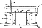
The present invention illustrated referring now to accompanying drawing, identical same parts of figure denote in the accompanying drawing.With reference to Fig. 1-3, the stereo set parts of a kind of all Source Musics 10 of the present invention comprise a shell 11.Shell 11 can support receiver circuit system (not shown); Be connected in each loud speaker 12 of receiver circuit system; Volume, tuning and shift knob (being respectively 15,16 and 17); Antenna 14; And auxiliary input jack 13.
Preferably, each loud speaker 12 and part shell 11 are coated with waterproof coating, such as a rubber coating or paint.In addition, other waterproof schemes can be used to protect loud speaker 12.Such as, United States Patent (USP) the 3rd, 391, No. 754, the 2nd, 829, No. 728 and the 2nd, 517, all disclosed some suitable waterproof schemes No. 138 and be hereby incorporated by.
Each button also can comprise and is used to stop water to enter the water-tight device of shell 11.This device can comprise the wallboard that is produced on shell 11 and/or each button, for water causes a labyrinth type path.In addition, some other waterproof scheme can be used for each button.Such as, United States Patent (USP) the 3rd, 391, No. 754, the 3rd, 277, No. 739 and the 1st, 162, disclosed some suitable waterproof schemes, and be hereby incorporated by for No. 793.
Antenna 14 is preferably made by a kind of flexible material, allows antenna 14 crooked and not disrumpent feelings.
Preferably, at least one protectiveness covering, protection or housing are connected in shell 11 flexibly.The example that this protectiveness hides is a protection whippletree 20.This covering or protection such as whippletree 20, can be made by aluminium or other suitable materials.Preferably, hide or protection, such as whippletree 20, make, such as ABS or polypropylene by a kind of plastics.Hide or protection, such as whippletree 20, can be injection molded.In addition, when hiding or protection when being configured as a kind of whippletree, plastics can inject a mould (that finishes preferably that mould charges is volume required only about half of, thereby is full of half mould), to wherein blasting air or gas, plastics are advanced second half mould and form a hollow cylinder device then.This process is called gas assisted injection moulding.
Preferably, protectiveness hides or protects and comprises that two are made other ring of branch and are connected in shell 11 whippletrees 20 of a side respectively.Protectiveness hides or protection also can comprise a handle 21, and it can be via being fixedly connected to each whippletree 20 such as each screw (not shown).Preferably, the shape of each whippletree 20 and/or handle 21 is to cause shell 11 not touched by any thing of being wider than handle 21 and/or each whippletree 20.This structure can make the impaired risk minimum of shell 11, but still allows wireless each workpiece of operation and/or can not cover the sound that is sent by loud speaker.
Skilled person in the art will appreciate that, protectiveness protection or whippletree 20 be preferably by interaction formula fastener, such as screw, bolt etc., can be secured to shell with loosening.Configuration protection protection or whippletree 20 in this wise, the user can change its some parts and need not to bear and change all protection, all whippletree 20 or the cost of broadcast receiver 10 when protectiveness protection or whippletree 20 damage.
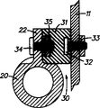
As previously mentioned, protectiveness protection or each whippletree 20 can be connected in shell 11 flexibly.This connection is achieved via each jockey 30.With reference to Fig. 4, a jockey 30 is arranged between whippletree 20 and the shell 11.Jockey 30 comprises an elastic insert 31, is preferably made by a kind of soft resilient material, such as rubber or syntheitic elastomers.Liner 31 can be connected in whippletree 20 via a screw 34 with screw-threaded engagement one nut 35.Liner 31 itself can be connected in shell 11 via a screw 32 with screw-threaded engagement one nut 33 again.Liner 31 can be molded on screw 32 and/or the nut 35.The vibrations minimum that this structure can make shell 11 and the Circuits System that is mounted in it be subjected to when broadcast receiver 10 falls.
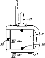
With reference to Fig. 2 and 6, shell 11 also can have a fan and be secured to its door 19 pivotly, the gateway of storing apparatus 50 is provided and allows the operator that one battery pack 60 is put into shell 11.Door 19 can be made it to be maintained in its closed position by keeper 18.Preferably, keeper 18 comprises and cares (overcenter) mechanism.
Door 19 can have a liner 19G disposed thereon and enter storing apparatus 50 with restriction water, is not complete waterproof even be.Preferably, liner 19G is made by rubber or a kind of artificial elastomeric material.Skilled person in the art will appreciate that, liner 19G can be arranged on the shell 11 and realize same function.
Preferably, storing apparatus 50 designs to such an extent that can put a battery pack 60 via a connector 56.Connector 56 has a structure that is suitable for contacting each termination of battery.Preferably, each termination of battery pack and connector will be with United States Patent (USP)s the 5th, 144, and disclosed mode is disposed among No. 217, and this full patent texts is hereby incorporated by reference.
Charger circuit system 43 can be fixedly connected to connector 56 and storing apparatus 50 the two.Connector 56 preferably is arranged on one and floats among the Socket casing 55, if so that broadcast receiver 10 falls the suffered vibrations minimum of battery pack 60 and Circuits System 43.Charger circuit system 43 allows to the batteries charging with different voltages, and this is being known in the art.
Socket casing 55 can be connected in shell 11 flexibly via a flexible liner 51.Preferably, liner 51 be substantially annular and make by a kind of soft resilient material, such as rubber or syntheitic elastomers.
Each retainer 52 can be contained on the shell 11 to prevent that liner 51 breaks away from engagement with shell 11 when pushing battery pack 60 is in place.Each retainer 52 can be secured to shell 11 and can have an annular substantially shape via each screw 53.Each retainer 52 can also prevent to take out Socket casing 55 by the stop surfaces that a possibility contact charging device circuit board 43 is set when removing battery pack 60.
One spring 54 also can be arranged on the door 19 on bias battery group 60, make it to be connected in connector 56.Spring 54 preferably has enough elasticity has different size with bias voltage battery pack.
Fig. 5 is the block diagram of a shell 11 inner circuit systems.Charger circuit system 43 is connected in a power supply 40.Power supply 40 can receive electric power from an AC power and/or when a battery pack is used as broadcast receiver 10 power supplys from charger 43 via connector 41.In addition, power supply 40 can provide electric power to charger 43, even so that charge to battery pack 60 when broadcast receiver 10 uses.
Power supply 40 also provides electric power to receiver circuit system 44.One switch 42 can be connected in shift knob 17 correctly to select each parts that receives electric power.Whether can select power supply 40:(a such as, user) both also provided electric power to charger 43 (being used for) to battery pack 60 chargings to receiver circuit system 44; (b) provide electric power from battery pack 60 to receiver circuit system 44; (c) do not provide electric power to any parts; Or the like.Switch 42 can comprise each relay, each transistor or other are at more known in the art switching device shifters.Preferably, power supply 40 can be accepted electric power from the battery pack with different voltages.
Receiver circuit system 44 can comprise three main modular: (a) radio tuner 45, are used to receive the radio signal that the reconciliation menstruation regulating is received by antenna 14; (b) amplifier 46, are connected in tuner 45, are used to amplify the radio signal through demodulation; And (c) each loud speaker 12, be connected in amplifier 46, be used for converting the signal that can listen to through an amplifying signal.Amplifier 46 also can amplify the signal that receives from an auxiliary input 13, allows the user to play an independent cassette tape recorder or a CD player by broadcast receiver 10.
Skilled person in the art will be appreciated that the peculiar Circuits System of each parts all is known among the present technique field.Such as, receiver circuit system 44 can comprise a FM front end integrated circuit, such as the LA1186N of Sanyo (SanYo) that uses with well-known way, in conjunction with a low-frequency power amplifier integrated circuit, such as the TA8227P of Toshiba (Toshiba) that uses with well-known way.Skilled person in the art can consult the technical descriptioon of these two kinds of integrated circuits to seek the further information about normal usage, ability, parameter etc.
Secondly, receiver circuit system 44 can replace with another Circuits System, so that generate audio signal with playing back music via the Circuits System that is used in combination with a cassette tape, CD or some other method to each loud speaker.
Preferably, charger 43 crown cap, such as lead, metals such as copper, gold are shielded, so that do not influence reception, processing and/or the amplification of radio receiver signal.Equally, charger 43 can dispose induction coil, or the filter of other types, so that make the influence minimum of charger to radio receiver signal etc.
Under the situation of this structure, can to a batteries charging, provide electric power by battery pack 60 being seated within the charger 43 such as, user, and from charger 43, take out battery pack 60 to battery pack 60.Battery pack 60 can inject an electric tool subsequently, such as drilling tool 100 (Fig. 5).In other words, the user can listen to broadcast receiver 10 programs in battery pack 60 chargings.In addition, the user can use hand Switching power 40, so that receiver circuit system 43 accepts power for operation from battery pack 60 rather than from AC power.
Skilled person in the art may consider some other about the thing in Gong the replacement of this disclosed device.But, all these replenish/or replacement all be considered to the thing of equivalence of the present invention.

Claims (20)

1. stereo set comprises:
One power supply;
One group charger is connected in power supply;
One is used to produce the circuit of an audio signal, is connected in power supply; And
One battery pack is used for using in conjunction with an electric tool, and battery pack removably is connected in group charger so that charging.
2. according to the described equipment of claim 1, wherein battery pack can be charged again.
3. according to the described equipment of claim 1, also comprise a shell, supporting power supply, group charger and voicefrequency circuit; And a storing apparatus, be used to put the battery pack that is connected in main shell flexibly.
4. according to the described equipment of claim 3, wherein storing apparatus comprises that a Socket casing and is arranged on the elastic insert between Socket casing and the main shell.
5. according to the described equipment of claim 4, wherein storing apparatus comprises that also at least one retainer that is arranged on the shell breaks away from engagement to prevent liner.
6. according to the described equipment of claim 4, wherein liner is made by rubber or syntheitic elastomers.
7. according to the described equipment of claim 3, also comprise one, hinge is connected in main shell and is opposite to storing apparatus.
8. according to the described equipment of claim 7, wherein door has setting spring thereon with the battery among being seated in storing apparatus towards a link position bias voltage.
9. according to the described equipment of claim 1, wherein circuit is a receiver circuit.
10. according to the described equipment of claim 1, wherein protectiveness protection is arranged on the described shell to prevent the damage to described shell.
11. according to the described equipment of claim 10, wherein said protection is a whippletree.
12. according to the described equipment of claim 10, wherein said protection adaptive as can be fixed in shell with loosening.
13. according to the described equipment of claim 10, wherein said protection is connected in shell flexibly.
14. according to the described equipment of claim 13, also comprise a connector, described protection be connected in shell flexibly.
15. according to the described equipment of claim 14, wherein connector comprises an elastic insert.
16. according to the described equipment of claim 15, wherein elastic insert is arranged between protection and the shell.
17. a method that is used for to a batteries charging comprises:
The one stereo set parts with a power supply are set; The circuit and one that one be connected in power supply, is used to produce an audio signal is connected in the charger of power supply;
Put battery pack among charger;
Provide electric power to battery pack; And
From charger, take out battery pack.
18. in accordance with the method for claim 17, also comprise battery pack injected an electric tool.
19. in accordance with the method for claim 17, be included in when battery pack provides electric power and provide electric power to receiver circuit.
20. in accordance with the method for claim 17, comprise that also the manual switchover power supply is so that provide electric power from battery pack to receiver circuit.
CNB991185552A 1998-09-15 1999-09-08 Strong acoustics equipment Expired - Fee Related CN1162039C (en)

Applications Claiming Priority (4)

Application Number Priority Date Filing Date Title
US15362198A 1998-09-15 1998-09-15
US09/153,621 1998-09-15
US09/262,751 US6427070B1 (en) 1999-03-04 1999-03-04 Heavy-duty audio equipment
US09/262,751 1999-03-04

Related Child Applications (2)

Application Number Title Priority Date Filing Date
CNB2004100346379A Division CN100394698C (en) 1998-09-15 1999-09-08 High strength audio equipment
CNA2008100926122A Division CN101257317A (en) 1998-09-15 1999-09-08 Heavy-duty audio equipment

Publications (2)

Publication Number Publication Date
CN1250345A CN1250345A (en) 2000-04-12
CN1162039C true CN1162039C (en) 2004-08-11

Family

ID=26850710

Family Applications (2)

Application Number Title Priority Date Filing Date
CNB2004100346379A Expired - Fee Related CN100394698C (en) 1998-09-15 1999-09-08 High strength audio equipment
CNB991185552A Expired - Fee Related CN1162039C (en) 1998-09-15 1999-09-08 Strong acoustics equipment

Family Applications Before (1)

Application Number Title Priority Date Filing Date
CNB2004100346379A Expired - Fee Related CN100394698C (en) 1998-09-15 1999-09-08 High strength audio equipment

Country Status (12)

Country Link
EP (3) EP1233664B1 (en)
JP (2) JP3851029B2 (en)
CN (2) CN100394698C (en)
AT (3) ATE228271T1 (en)
DE (3) DE69904005T2 (en)
DK (3) DK1233664T3 (en)
ES (1) ES2183487T3 (en)
HK (1) HK1066349A1 (en)
ID (1) ID23762A (en)
MY (1) MY121364A (en)
PT (1) PT987783E (en)
TW (1) TW432810B (en)

Families Citing this family (16)

* Cited by examiner, † Cited by third party
Publication number Priority date Publication date Assignee Title
CN101262080B (en) * 2001-11-09 2010-11-10 密尔沃基电动工具公司 Battery charger and electronic element using power tool battery
US7332889B2 (en) 2001-11-09 2008-02-19 Milwaukee Electric Tool Corporation Battery charger
US7609027B2 (en) 2001-11-09 2009-10-27 Milwaukee Electric Tool Corporation Electrical component, audio component, or electrical combination having a selectively connectable battery charger
US20050078834A1 (en) * 2003-10-14 2005-04-14 Credo Technology Corporation Portable battery charging and audio unit
US7835534B2 (en) 2003-10-14 2010-11-16 Robert Bosch Gmbh Battery charging jobsite lunchbox
US8604752B2 (en) * 2003-10-14 2013-12-10 Robert Bosch Gmbh Portable battery charging and audio unit
JP4624740B2 (en) * 2004-08-26 2011-02-02 株式会社マキタ Power tool storage case
US7741809B2 (en) 2006-01-06 2010-06-22 Milwaukee Electric Tool Corporation Electrical component including a battery receptacle for including a battery
DE102008035766A1 (en) 2008-07-31 2010-02-04 Metabowerke Gmbh Radio device for use in battery pack of cordless screwdriver, has housing and contact arrangement designed such that device is connected and operated with charging device for battery pack for electrical hand-tool device
JP5634740B2 (en) * 2010-04-28 2014-12-03 株式会社マキタ Electrical equipment system
JP5670839B2 (en) 2011-06-30 2015-02-18 株式会社マキタ radio
DE102012203485A1 (en) 2012-03-06 2013-09-12 Robert Bosch Gmbh Construction site radio device
JP6143086B2 (en) * 2013-06-14 2017-06-07 日立工機株式会社 Electrical equipment
US9693470B2 (en) 2013-06-14 2017-06-27 Hitachi Koki Co., Ltd. Electric device with surrounding protective frame
JP2015192565A (en) * 2014-03-28 2015-11-02 日立工機株式会社 Charging apparatus and electric power supply
CN113508491B (en) * 2019-03-01 2023-06-30 米沃奇电动工具公司 Power tool and battery pack for use therewith

Family Cites Families (14)

* Cited by examiner, † Cited by third party
Publication number Priority date Publication date Assignee Title
US3971889A (en) * 1974-04-22 1976-07-27 Hays Robert A Portable bar adapted for mounting electronic equipment
US4050493A (en) * 1976-01-05 1977-09-27 Jin Sul Cho Ladies handbag and radio
US4089044A (en) * 1977-03-15 1978-05-09 Motorola, Inc. Housing assembly for miniaturized battery operated electrical apparatus
US4225970A (en) * 1978-11-24 1980-09-30 Motorola, Inc. Splash proof portable two-way data terminal/radio
US4709201A (en) * 1985-10-24 1987-11-24 General Electric Company Portable radio battery pack with on-off switch
DE3786170T2 (en) * 1987-10-06 1993-09-23 Black & Decker Inc BATTERY KIT.
US5002184A (en) * 1989-06-12 1991-03-26 Grid Systems Corporation Soft case protection for a hand held computer
US5090562A (en) * 1991-04-23 1992-02-25 Grullemans Winslow C Protective case for portable sound-playing device
US5424725A (en) * 1993-02-25 1995-06-13 Motorola, Inc. Battery retainer with integral mechanical shock isolation
US5680026A (en) * 1994-03-21 1997-10-21 Tyton Corporation Tool belt with battery assembly
US5606241A (en) * 1994-08-22 1997-02-25 Motorola, Inc. Apparatus for determining radio state during charging in order to provide charge compensation
ES2112212B1 (en) * 1996-05-21 1998-11-16 Maier S Coop Ltda PROTECTIVE GUARD FOR A MOBILE PHONE.
CN2260288Y (en) * 1996-05-24 1997-08-20 青岛海尔冷冻设备有限公司 Protective rod of refrigerator
US6007940A (en) * 1997-11-26 1999-12-28 Celgard Llc Portable power tool having low rate, rechargeable batteries

Also Published As

Publication number Publication date
DE69928579T3 (en) 2014-04-03
DE69928579D1 (en) 2005-12-29
EP0987783B1 (en) 2002-11-20
CN1250345A (en) 2000-04-12
EP0987783A2 (en) 2000-03-22
ID23762A (en) 2000-05-11
EP0987783A3 (en) 2000-05-31
ATE315887T1 (en) 2006-02-15
MY121364A (en) 2006-01-28
PT987783E (en) 2003-03-31
CN100394698C (en) 2008-06-11
EP1233665A2 (en) 2002-08-21
HK1066349A1 (en) 2005-03-18
DK0987783T3 (en) 2002-12-16
EP1233665A3 (en) 2004-12-01
ATE228271T1 (en) 2002-12-15
TW432810B (en) 2001-05-01
DK1233664T3 (en) 2006-04-18
EP1233664B1 (en) 2006-01-11
ATE311093T1 (en) 2005-12-15
DK1233665T3 (en) 2006-02-13
DE69904005T2 (en) 2003-07-31
DE69929368T2 (en) 2006-09-21
JP3851029B2 (en) 2006-11-29
ES2183487T3 (en) 2003-03-16
EP1233664A2 (en) 2002-08-21
JP4417923B2 (en) 2010-02-17
DE69904005D1 (en) 2003-01-02
EP1233664A3 (en) 2004-12-01
DE69929368D1 (en) 2006-04-06
JP2006262529A (en) 2006-09-28
CN1534881A (en) 2004-10-06
EP1233665B2 (en) 2013-11-20
DE69928579T2 (en) 2006-08-03
JP2000092726A (en) 2000-03-31
EP1233665B1 (en) 2005-11-23

Similar Documents

Publication Publication Date Title
CN1162039C (en) Strong acoustics equipment
US7466974B2 (en) Heavy-duty audio equipment
USRE44557E1 (en) Ruggedized tradesworkers radio
CN101194405B (en) Portable battery charging and audio unit
EP0583900A1 (en) Improved headphone apparatus
US6091812A (en) Apparatus and method for automatically switching a headset between a telephone and a second audio source
CN1314025A (en) Methods for adjusting audio signals responsive to changes ina power supply level and related communications devices
WO2016168887A1 (en) Electric stringed instruments
US6091225A (en) Battery charging system having a speaker and a mode changing switch
CN1109393C (en) Portable electronic device and method
CN101257317A (en) Heavy-duty audio equipment
CN217283324U (en) Bluetooth headset circuit and TWS bluetooth headset
WO2006100911A1 (en) Portable apparatus with built-in fm transmitter
KR20050076199A (en) Audio system for wireless terminal
KR20060033543A (en) Device for keeping a portable appliance
JP2000069337A (en) Video camera

Legal Events

Date Code Title Description
C06 Publication
PB01 Publication
C10 Entry into substantive examination
SE01 Entry into force of request for substantive examination
C14 Grant of patent or utility model
GR01 Patent grant
CF01 Termination of patent right due to non-payment of annual fee

Granted publication date: 20040811

Termination date: 20140908

EXPY Termination of patent right or utility model
C35 Partial or whole invalidation of patent or utility model
IP01 Partial invalidation of patent right

Commission number: 4W102073

Conclusion of examination: Declaring that part 99118555.2 of the patent for invention is invalid, the patent shall be maintained on the basis of claim 4-6 and 10-16.

Decision date of declaring invalidation: 20140430

Decision number of declaring invalidation: 22709

Denomination of invention: Strong acoustics equipment

Granted publication date: 20040811

Patentee: Black & Decker Inc.