CN116195954A - Operation unit and endoscope - Google Patents
Operation unit and endoscope Download PDFInfo
- Publication number
- CN116195954A CN116195954A CN202211430262.2A CN202211430262A CN116195954A CN 116195954 A CN116195954 A CN 116195954A CN 202211430262 A CN202211430262 A CN 202211430262A CN 116195954 A CN116195954 A CN 116195954A
- Authority
- CN
- China
- Prior art keywords
- outer tube
- base end
- axial direction
- vertical direction
- grip
- Prior art date
- Legal status (The legal status is an assumption and is not a legal conclusion. Google has not performed a legal analysis and makes no representation as to the accuracy of the status listed.)
- Pending
Links
Images


Classifications
-
- A—HUMAN NECESSITIES
- A61—MEDICAL OR VETERINARY SCIENCE; HYGIENE
- A61B—DIAGNOSIS; SURGERY; IDENTIFICATION
- A61B1/00—Instruments for performing medical examinations of the interior of cavities or tubes of the body by visual or photographical inspection, e.g. endoscopes; Illuminating arrangements therefor
- A61B1/00002—Operational features of endoscopes
- A61B1/00039—Operational features of endoscopes provided with input arrangements for the user
- A61B1/00042—Operational features of endoscopes provided with input arrangements for the user for mechanical operation
-
- A—HUMAN NECESSITIES
- A61—MEDICAL OR VETERINARY SCIENCE; HYGIENE
- A61B—DIAGNOSIS; SURGERY; IDENTIFICATION
- A61B1/00—Instruments for performing medical examinations of the interior of cavities or tubes of the body by visual or photographical inspection, e.g. endoscopes; Illuminating arrangements therefor
- A61B1/005—Flexible endoscopes
- A61B1/0051—Flexible endoscopes with controlled bending of insertion part
-
- A—HUMAN NECESSITIES
- A61—MEDICAL OR VETERINARY SCIENCE; HYGIENE
- A61B—DIAGNOSIS; SURGERY; IDENTIFICATION
- A61B1/00—Instruments for performing medical examinations of the interior of cavities or tubes of the body by visual or photographical inspection, e.g. endoscopes; Illuminating arrangements therefor
- A61B1/00064—Constructional details of the endoscope body
- A61B1/00066—Proximal part of endoscope body, e.g. handles
-
- A—HUMAN NECESSITIES
- A61—MEDICAL OR VETERINARY SCIENCE; HYGIENE
- A61B—DIAGNOSIS; SURGERY; IDENTIFICATION
- A61B1/00—Instruments for performing medical examinations of the interior of cavities or tubes of the body by visual or photographical inspection, e.g. endoscopes; Illuminating arrangements therefor
- A61B1/00064—Constructional details of the endoscope body
- A61B1/00071—Insertion part of the endoscope body
- A61B1/0008—Insertion part of the endoscope body characterised by distal tip features
- A61B1/00096—Optical elements
-
- A—HUMAN NECESSITIES
- A61—MEDICAL OR VETERINARY SCIENCE; HYGIENE
- A61B—DIAGNOSIS; SURGERY; IDENTIFICATION
- A61B1/00—Instruments for performing medical examinations of the interior of cavities or tubes of the body by visual or photographical inspection, e.g. endoscopes; Illuminating arrangements therefor
- A61B1/00112—Connection or coupling means
- A61B1/00114—Electrical cables in or with an endoscope
-
- A—HUMAN NECESSITIES
- A61—MEDICAL OR VETERINARY SCIENCE; HYGIENE
- A61B—DIAGNOSIS; SURGERY; IDENTIFICATION
- A61B1/00—Instruments for performing medical examinations of the interior of cavities or tubes of the body by visual or photographical inspection, e.g. endoscopes; Illuminating arrangements therefor
- A61B1/00163—Optical arrangements
- A61B1/00165—Optical arrangements with light-conductive means, e.g. fibre optics
-
- A—HUMAN NECESSITIES
- A61—MEDICAL OR VETERINARY SCIENCE; HYGIENE
- A61B—DIAGNOSIS; SURGERY; IDENTIFICATION
- A61B1/00—Instruments for performing medical examinations of the interior of cavities or tubes of the body by visual or photographical inspection, e.g. endoscopes; Illuminating arrangements therefor
- A61B1/00163—Optical arrangements
- A61B1/00174—Optical arrangements characterised by the viewing angles
- A61B1/00179—Optical arrangements characterised by the viewing angles for off-axis viewing
-
- A—HUMAN NECESSITIES
- A61—MEDICAL OR VETERINARY SCIENCE; HYGIENE
- A61B—DIAGNOSIS; SURGERY; IDENTIFICATION
- A61B1/00—Instruments for performing medical examinations of the interior of cavities or tubes of the body by visual or photographical inspection, e.g. endoscopes; Illuminating arrangements therefor
- A61B1/005—Flexible endoscopes
- A61B1/0051—Flexible endoscopes with controlled bending of insertion part
- A61B1/0052—Constructional details of control elements, e.g. handles
-
- A—HUMAN NECESSITIES
- A61—MEDICAL OR VETERINARY SCIENCE; HYGIENE
- A61B—DIAGNOSIS; SURGERY; IDENTIFICATION
- A61B1/00—Instruments for performing medical examinations of the interior of cavities or tubes of the body by visual or photographical inspection, e.g. endoscopes; Illuminating arrangements therefor
- A61B1/04—Instruments for performing medical examinations of the interior of cavities or tubes of the body by visual or photographical inspection, e.g. endoscopes; Illuminating arrangements therefor combined with photographic or television appliances
- A61B1/05—Instruments for performing medical examinations of the interior of cavities or tubes of the body by visual or photographical inspection, e.g. endoscopes; Illuminating arrangements therefor combined with photographic or television appliances characterised by the image sensor, e.g. camera, being in the distal end portion
- A61B1/051—Details of CCD assembly
-
- G—PHYSICS
- G02—OPTICS
- G02B—OPTICAL ELEMENTS, SYSTEMS OR APPARATUS
- G02B23/00—Telescopes, e.g. binoculars; Periscopes; Instruments for viewing the inside of hollow bodies; Viewfinders; Optical aiming or sighting devices
- G02B23/24—Instruments or systems for viewing the inside of hollow bodies, e.g. fibrescopes
- G02B23/2407—Optical details
- G02B23/2423—Optical details of the distal end
- G02B23/243—Objectives for endoscopes
-
- G—PHYSICS
- G02—OPTICS
- G02B—OPTICAL ELEMENTS, SYSTEMS OR APPARATUS
- G02B23/00—Telescopes, e.g. binoculars; Periscopes; Instruments for viewing the inside of hollow bodies; Viewfinders; Optical aiming or sighting devices
- G02B23/24—Instruments or systems for viewing the inside of hollow bodies, e.g. fibrescopes
- G02B23/2476—Non-optical details, e.g. housings, mountings, supports
Landscapes
- Health & Medical Sciences (AREA)
- Life Sciences & Earth Sciences (AREA)
- Surgery (AREA)
- Physics & Mathematics (AREA)
- Optics & Photonics (AREA)
- Engineering & Computer Science (AREA)
- Biomedical Technology (AREA)
- General Health & Medical Sciences (AREA)
- Pathology (AREA)
- Nuclear Medicine, Radiotherapy & Molecular Imaging (AREA)
- Biophysics (AREA)
- Heart & Thoracic Surgery (AREA)
- Medical Informatics (AREA)
- Molecular Biology (AREA)
- Animal Behavior & Ethology (AREA)
- Radiology & Medical Imaging (AREA)
- Public Health (AREA)
- Veterinary Medicine (AREA)
- Mechanical Engineering (AREA)
- Astronomy & Astrophysics (AREA)
- General Physics & Mathematics (AREA)
- Endoscopes (AREA)
- Instruments For Viewing The Inside Of Hollow Bodies (AREA)
Abstract
The invention provides an operation part which enables a doctor to easily grasp the up-down direction of an observation image outputted from an imaging part and displayed on a display, and an endoscope provided with the operation part. An operation unit according to the present invention is an operation unit connected to a proximal end side of an insertion unit of an endoscope, the insertion unit including an optical system and an imaging unit that images light passing through the optical system, the operation unit including: a holding portion extending in an axial direction of an insertion shaft of the insertion portion; a first plane portion formed at a position on an upper side of an outer surface of the grip portion in the vertical direction, and extending in the axial direction and being perpendicular to the vertical direction, when a vertical direction indicating an up-down direction of an image formed based on an imaging signal output from the imaging portion is set as the up-down direction; and a second flat surface portion formed at a position on the outer surface of the grip portion, the position indicating the lower side in the up-down direction, and extending in the axial direction and being perpendicular to the up-down direction.
Description
Technical Field
The present invention relates to an operation portion connected to a proximal end side of an insertion portion of an endoscope, and an endoscope provided with the operation portion.
Background
As an endoscope used for an endoscopic surgical operation or the like, a rigid scope (rigid endoscope) is known (refer to patent document 1). As the rigid mirror, a squint mirror having a view direction (observation direction, photographing direction) with respect to the oblique front of the insertion axis of the insertion portion is known. The strabismus mirror is provided with: an insertion portion inserted into a patient; an operation section connected to the base end side of the insertion section; and an optical system provided at a distal end portion of the insertion portion, and an imaging portion for imaging light passing through the optical system. The observation image captured by the imaging unit is output to a display via a cable. Thereby, the physician can view the patient's body through the display. Among such oblique mirrors, patent documents 2 to 4 describe oblique mirrors in which the direction of the visual field can be changed by the operator operating the operation unit.
The operation unit of the oblique mirror described in patent document 2 and patent document 3 includes a cylindrical grip portion (handle) gripped by a doctor, and a rotary operation member (rotary body, actuator) provided on the distal end side of the handle and rotatable in the axial direction of the insertion shaft of the insertion portion. In the oblique mirror described in patent document 2 and patent document 3, the operator rotates the holding portion, thereby changing the visual field direction of the oblique mirror by rotating the insertion portion in the axial direction.
The operation unit of the mirror described in patent document 4 includes a handle and a rotary wheel provided on the front end side of the handle. In the endoscope described in patent document 4, an operator rotates an operation handle, and thereby rotates an optical system provided at a distal end portion of an insertion portion (an endoscope shaft portion). On the other hand, the rotary wheel prevents the imaging section in the insertion section from rotating following the rotational movement of the optical system during the rotation operation of the handle. Thus, in the screen of the display, the vertical rotation of the observation image captured by the oblique mirror is prevented.
Patent document 1: international publication No. 2018/021583
Patent document 2: japanese patent application laid-open No. 2021-510103
Patent document 3: U.S. Pat. No. 5621830 Specification
Patent document 4: japanese patent application laid-open No. 2018-32014
It is desirable for a doctor (including a care giver, hereinafter the same) to always grasp the vertical direction of an observation image displayed on a display and perform an operation while maintaining a state (level) in which the vertical direction coincides with the vertical direction of the display. However, in the oblique mirror described in patent document 2 and patent document 3, the doctor cannot grasp the vertical direction of the observation image displayed on the display.
In the squint mirrors described in patent documents 2 and 3, the insertion section and the imaging section integrally rotate in response to a rotation operation of the rotation operation member by the doctor. Therefore, in the squint mirrors described in patent document 2 and patent document 3, the vertical direction of the observation image displayed on the display cannot be kept constant.
On the other hand, in the oblique mirror described in patent document 4, by providing the rotary wheel, the vertical direction of the observation image displayed on the display can be kept constant even when the handle is rotated. However, the operation unit described in patent document 4 is similar to the operation units described in patent document 2 and patent document 3, and the doctor cannot grasp the vertical direction of the observation image on the display, so that it is difficult to match the vertical direction of the observation image with the vertical direction of the display.
Disclosure of Invention
The present invention has been made in view of such circumstances, and an object thereof is to provide an operation unit capable of easily grasping an observation image outputted from an imaging unit and displayed on a display in the up-down direction, and an endoscope including the operation unit.
An operation unit for achieving the object of the present invention, which is connected to a proximal end side of an insertion unit of an endoscope, and which is provided with an optical system and an imaging unit that images light passing through the optical system, the operation unit comprising: a holding portion extending in an axial direction of an insertion shaft of the insertion portion; a first plane portion formed at a position on an upper side of an outer surface of the grip portion in the vertical direction, and extending in the axial direction and being perpendicular to the vertical direction, when a vertical direction indicating an up-down direction of an image formed based on an imaging signal output from the imaging portion is set as the up-down direction; and a second flat surface portion formed at a position on the outer surface of the grip portion, the position indicating the lower side in the up-down direction, and extending in the axial direction and being perpendicular to the up-down direction. The image referred to herein is a display image that is output from the image pickup unit to a display (display unit) and displayed on the display.
According to this operation unit, the doctor can easily grasp the vertical direction of the image output from the imaging unit.
In the operation unit according to another aspect of the present invention, the grip unit includes: when the first curved surface portion is perpendicular to both the axial direction and the vertical direction, the first curved surface portion connects the side edge portion on the one side in the perpendicular direction of the first planar portion and the side edge portion on the one side in the perpendicular direction of the second planar portion, and bulges toward the one side in the perpendicular direction; and a second curved surface portion that connects the side edge portion on the other side in the vertical direction of the first planar portion and the side edge portion on the other side in the vertical direction of the second planar portion, and bulges toward the other side in the vertical direction. Thus, the doctor can easily grasp the first flat surface portion and the second flat surface portion formed on the outer surface of the grip portion, and further, the stability of the doctor when gripping the grip portion can be improved.
In the operation portion according to another aspect of the present invention, the base end portion of the grip portion is formed in a dome shape. When the holding portion is held by the doctor, the base end portion is brought into contact with the palm of the doctor, so that the stability of the holding portion when held by the doctor can be improved.
In the operation portion according to another aspect of the present invention, the first flat portion is formed from the distal end portion of the grip portion over the proximal end portion of the grip portion, the second flat portion is formed from the distal end portion of the grip portion over a position on the front side of the proximal end portion of the grip portion, and a part of the proximal end portion of the grip portion is a bulge portion bulging downward in the up-down direction from the second flat portion. Thus, when the holding portion is held by the doctor, the middle finger or ring finger of the hand comes into contact with the bulge portion, so that the stability of the holding portion when held by the doctor can be improved.
An operation unit according to another aspect of the present invention includes: and an inclined plane part connected between the base end of the second plane part and the bulge part and inclined from the base end of the second plane part to the lower side of the base end in the vertical direction. Thus, when the holding portion is held by the doctor, the middle finger or ring finger of the hand comes into contact with the inclined plane portion, so that the stability of the holding portion when held by the doctor can be improved.
An operation unit according to another aspect of the present invention includes: and a cable insertion portion protruding from a position offset from a base end apex of the base end portion of the grip portion toward a lower side in an up-down direction, for inserting a cable connected to the imaging portion, the cable insertion portion protruding in a direction of a base end side of the base end portion of the grip portion and protruding in a direction inclined toward the lower side in the up-down direction with respect to the axial direction when viewed from a vertical direction perpendicular to both the axial direction and the up-down direction. This ensures the amount of the external cable drawn out from the proximal end portion, and further prevents the cable from coming into contact with the patient and the doctor.
In the operation unit according to another aspect of the present invention, the insertion unit includes: an outer tube which is held rotatably relative to the front end side of the holding portion in the axial direction of the insertion shaft; the outer cylinder is inserted into the outer tube and integrally rotates along the axial direction with the outer tube; and an inner tube inserted into the outer tube and rotatable relative to the outer tube and the outer tube in a radial direction, wherein when the optical system is provided on the distal end side of the outer tube and the imaging unit is provided on the distal end side of the inner tube, the imaging device comprises: an inner tube fixing part which is arranged in the holding part and can not rotate relative to the holding part along the axial direction so as to fix the base end side of the inner tube; and an annular rotation operation member fixed to the base end side of the outer tube and rotating the outer tube in the axial direction.
In the operation portion according to another aspect of the present invention, the grip portion is made of a rubber material or a resin material. Thus, the grip portion is hard to slide in the hand.
An endoscope for achieving the object of the present invention is provided with: an insertion section provided with an optical system and an imaging section for imaging light passing through the optical system; and the operation part is connected with the base end side of the insertion part.
In an endoscope according to another aspect of the present invention, an insertion portion includes: an outer tube which is held rotatably relative to the front end side of the holding portion in the axial direction of the insertion shaft; the outer cylinder is inserted into the outer tube and integrally rotates along the axial direction with the outer tube; an inner tube inserted into the outer tube and rotatable relative to the outer tube and the outer tube in a direction of the axis; and an inner tube fixing portion provided so as not to be relatively rotatable with respect to the grip portion in the axial direction inside the grip portion to fix a base end side of the inner tube, an optical system being provided on a front end side of the outer tube, and an imaging portion being provided on a front end side of the inner tube.
An endoscope according to another aspect of the present invention includes: and a ring-shaped rotary operation member fixed to the base end side of the outer tube to rotate the outer tube in the axial direction.
In the endoscope according to another aspect of the present invention, the optical system includes a refractive optical element that refracts light incident from a direction inclined with respect to the insertion axis in parallel with the insertion axis.
Effects of the invention
The invention can make the doctor grasp the up-down direction of the image outputted from the image pickup part and displayed on the display easily.
Drawings
Fig. 1 is a block diagram of an endoscope system including a tilt mirror.
Fig. 2 is an enlarged cross-sectional view of the distal end portion of the insertion portion.
Fig. 3 is a cross-sectional view of a main portion of the grip and a knob.
Fig. 4 is a cross-sectional view of the outer tube and the housing.
Fig. 5 is an enlarged sectional view of the case and the cylindrical portion.
Fig. 6 is an explanatory diagram for explaining a relationship between an up-down direction indicating an up-down direction of the imaging system and an up-down direction indicating an up-down direction of an observation image displayed on the display.
Fig. 7 is a side view of the operation section.
Fig. 8 is a plan view of the operation section.
Fig. 9 is a bottom view of the operation portion.
Detailed Description
Fig. 1 is a block diagram of an endoscope system 12 including a tilt mirror 10. As shown in fig. 1, the endoscope system 12 includes a scope 10, a processor device 14, a display 16, and a light source device 18. The oblique mirror 10 is an example of an endoscope of the present invention.
The oblique mirror 10 is a so-called rigid mirror, and includes an insertion portion 20 and an operation portion 21. The insertion portion 20 is formed in a tubular shape (tubular shape) and is inserted into the body of the patient. The insertion portion 20 has a distal end, a proximal end, and an insertion axis Ax (also referred to as a long axis), and an outer peripheral wall is formed of an outer tube 30 (also referred to as an outer sleeve) described later. A camera unit 24 described later is provided at the distal end portion of the insertion portion 20. Further, a first signal cable 26 and a light guide 28 are inserted into the insertion portion 20.
The first signal cable 26 connects the camera unit 24 and the processor device 14, which will be described later, together with a second signal cable 27, which will be described later. The front end portion of the first signal cable 26 is connected to the camera unit 24, and the base end portion of the first signal cable 26 is connected to the second signal cable 27 in the operation unit 21. The distal end portion (light emitting end surface) of the light guide 28 is provided on the distal end surface of the insertion portion 20, and the proximal end portion (light incident end surface) thereof is connected to the light source device 18. In this example, the first signal cable 26 and the second signal cable 27, which are examples of the cable of the present invention, are illustrated as a multi-core cable in which a plurality of bare wires (signal wires) are bundled, and a shield conductor is provided around the bare wires, and these are accommodated in a cylindrical sheath.
The light guide 28 has a light emitting end 28C (see fig. 2) on the front end side thereof, and the light emitting end 28C is disposed on the front end side of the outer tube 30. The light guide 28 has a light incident end (not shown) on its base end side, and the light incident end is connected to the light source device 18. As the light guide 28, for example, a structure in which a plurality of optical fibers are bundled into 1 optical cable is employed, and the structure is flexible.
The operation portion 21 is connected to the base end side of the insertion portion 20. The operation unit 21 is held by the doctor at the time of operation of the squint 10, and receives a rotation operation of rotating the squint 10 in the axial direction B of the insertion axis Ax (refer to the optical axis OA of fig. 2), that is, in the circumferential direction of the insertion unit 20 and the operation unit 21, from the doctor. The operation unit 21 is composed of a tubular grip 22 gripped by a doctor and a tubular (annular) knob 36 for receiving a rotation operation in the visual field direction. The knob 36 is an example of a rotary operation member of the present invention.
The grip 22 is formed of a rubber material or a resin material that withstands the sterilization process of the autoclave, and has a size suitable for the hand of the doctor. Examples of such rubber materials include silicone rubber and fluororubber. The resin material may include PPSU (PolyPhenylSulfone) and PEEK (Poly Ether Ether Ketone: polyetheretherketone). As a result, the grip 22 is less likely to slide in the hand, that is, is less likely to rotate in the axial direction B than when the grip 22 is formed of a metal material.
The outer tube 30 is rotatably held at the distal end portion of the grip 22 in the axial direction B. An external cable 72 is connected to the base end portion of the grip 22. The second signal cable 27 and the light guide 28 described above are inserted into the external cable 72.
Further, the details of the grip portion 22 will be described later, and an airtight space and a non-airtight space are provided in the grip portion, and the base end portion of the first signal cable 26 and the tip end portion of the second signal cable 27 are connected at the boundary between the two spaces (see fig. 3). The base end portion of the second signal cable 27 is connected to the processor device 14. Thereby, the camera unit 24 and the processor device 14 are electrically connected via the first signal cable 26 and the second signal cable 27.
The knob 36 is fixed to the proximal end side of the outer tube 30, and is disposed between the insertion portion 20 and the grip portion 22. The knob 36 is a member for changing the visual field direction of the mirror 10 by rotating the outer tube 30 about the grip 22 in the axial direction B.
The processor device 14 generates an observation image 300 (moving image) in the patient based on the imaging signals input from the camera unit 24 via the first signal cable 26 and the second signal cable 27, and causes the display 16 to display the observation image 300. The observation image 300 corresponds to an example of the image of the present invention.
The light source device 18 supplies illumination light to the light guide 28. Thereby, illumination light is emitted from a light emitting end 28C (see fig. 2) of the light guide 28 provided on the front end surface of the insertion portion 20.
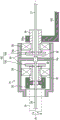
Fig. 2 is an enlarged cross-sectional view of the distal end portion of the insertion portion 20. As shown in fig. 2, the insertion portion 20 includes a substantially tubular outer tube 30, an outer tube 32, and an inner tube 34, which are parallel to the insertion axis Ax. The outer tube 30 constitutes the outer peripheral wall of the insertion portion 20 as already described. The opening of the distal end portion of the outer tube 30 is inclined from a posture perpendicular to the insertion axis Ax. The proximal end portion of the outer tube 30 is held rotatably in the axial direction B by the distal end portion of the grip portion 22, although details will be described later. A knob 36 is fitted and fixed to the base end of the outer tube 30.
The outer tube 32 is inserted and disposed inside the outer tube 30. A front end optical system 40 constituting a camera unit 24 described later is provided at the front end portion of the outer tube 32. The proximal end portion of the outer tube 32 is connected to a housing 74 (see fig. 3) in the grip 22, although details will be described later. A space 31 for disposing the light guide 28 is formed between the inner peripheral surface of the outer tube 30 and the outer peripheral surface of the outer tube 32.
The inner tube 34 is inserted and disposed inside the outer tube 32. A first signal cable 26 is inserted into the inner tube 34. A base end optical system 50 and an imaging unit 60 constituting a camera unit 24 described later are provided at the tip end portion of the inner tube 34. The proximal end portion of the inner tube 34 is connected to a connecting member 90 (see fig. 3) in the operation unit 21, although details thereof will be described later.
The camera unit 24 includes a front-end optical system 40, a base-end optical system 50, and an imaging unit 60. Note that symbol OA in the figure is an optical axis of the optical system of the camera unit 24.
The front end optical system 40 is an example of the optical system of the present invention, and is provided at the front end of the outer tube 32. The front-end optical system 40 is a oblique-view optical system that refracts light incident from a direction oblique to the insertion axis Ax in a direction parallel to the insertion axis Ax and guides the light to the base-end optical system 50. The front-end optical system 40 includes a front-end body 42 and a front-end barrel 44 provided to the front-end body 42.
The tip body 42 constitutes the tip of the insertion portion 20 (outer tube 32) and is a cover that covers the tip barrel 44. The distal end portion main body 42 is formed in a substantially cylindrical shape parallel to the insertion axis Ax. A cover glass 46 having an inclined posture corresponding to the inclined angle of an objective lens 48a in the front lens barrel 44 described later is provided in the opening portion on the front end side of the front end body 42.
The distal end portion main body 42 is fixed to the inner peripheral surface of the outer tube 30. As a result, when the outer tube 30 rotates in the axial direction B, the front end optical system 40 and the outer tube 32 rotate integrally with the outer tube 30 in the axial direction B.
An objective lens 48a, a prism 48b, and a lens 48c are accommodated in the front barrel 44. The objective lens 48a is inclined from a posture perpendicular to the insertion axis Ax, and faces the cover glass 46. The objective lens 48a emits light incident through the cover glass 46 toward the prism 48 b. The prism 48b is an example of the refractive optical element of the present invention, and refracts light incident from the objective lens 48a, that is, light incident from a direction inclined with respect to the insertion axis Ax in a direction parallel (including substantially parallel) to the insertion axis Ax, and then emits the light toward the lens 48c. Thus, the viewing direction of the squint mirror 10 is inclined with respect to the insertion axis Ax. The lens 48c is oriented perpendicular to the insertion axis Ax, and emits light incident from the prism 48b toward a lens 56 in a base end mirror tube 52 of a base end optical system 50, which will be described later.
The configuration of the optical system in the front end mirror tube 44 is not particularly limited as long as the light incident from a direction inclined with respect to the insertion axis Ax can be guided into the base end mirror tube 52.
A cylindrical portion 45 extending from the base end side thereof is formed on the front end barrel 44. The cylindrical portion 45 is fitted to the tip end portion of a base end barrel 52 described later so as to be rotatable about the axial direction. Thus, the base end mirror 52 is fitted to the tip end mirror 44 so as to be rotatable relative to each other in the axial direction.
The base end optical system 50 is provided at the front end portion of the inner tube 34, and guides light incident from the front end barrel 44 to the image pickup unit 60. The base optical system 50 includes a base barrel 52, a bracket 54, and a prism 55.
The base end mirror 52 is fixed to the front end of the inner tube 34 via a bracket 54. As described above, the distal end portion of the base barrel 52 is fitted in the opening portion on the base end side of the tubular portion 45 so as to be rotatable about the axial direction B. Thus, the other of the front end barrel 44 and the base end barrel 52 is rotatable about the axial direction B. As a result, the inner tube 34 is rotatable relative to the outer tube 32 in the axial direction B.
A plurality of lenses 56 having optical axes 0A parallel to the insertion axis Ax are provided in the base end mirror tube 52. Each lens 56 emits light incident from the front end barrel 44 toward the prism 55.
The bracket 54 is formed in a substantially cylindrical shape parallel to the insertion axis Ax, and is fixed to the front end portion of the inner tube 34. The bracket 54 is fixedly connected (externally fitted) to the base end portion of the base end barrel 52. Accordingly, since the inner tube 34 and the base end mirror tube 52 are connected by the bracket 54, the inner tube 34, the base end mirror tube 52, and the bracket 54 are integrally rotatable relative to the outer tube 32 in the axial direction B.
A prism 55 is held in an opening on the base end side of the bracket 54, and an imaging unit 60 described later is further held via the prism 55. Therefore, the imaging unit 60 is rotatable relative to the outer tube 32 in the axial direction B integrally with the inner tube 34 and the base end mirror tube 52 via the bracket 54 and the prism 55.
The prism 55 refracts the light incident through the base end mirror cylinder 52 by 90 degrees. In addition, a mirror may be used instead of the prism 55.
The image pickup unit 60 picks up light (observation image 300) that passes through the front end barrel 44 and the base end barrel 52 and is reflected by the prism 55. The imaging unit 60 includes an imaging element 64 and a circuit board 66.
The image pickup element 64 is connected (fixed) to the prism 55 in a state of being mounted on the circuit board 66, and is mounted on the bracket 54 via the prism 55. Then, the image pickup element 64 picks up the light refracted by the prism 55 and outputs an image pickup signal. As the image pickup element 64, a CCD (Charge Coupled Device: charge coupled device) type image sensor or a CMOS (Complementary Metal Oxide Semiconductor: complementary metal oxide semiconductor) type image sensor is used.
In the present embodiment, the imaging element 64 is mounted on the bracket 54 via the prism 55, but the imaging element 64 may be directly mounted on the opening on the base end side of the bracket 54. In this case, the image pickup element 64 has a light receiving surface perpendicular to the optical axis 0A by being held by the bracket 54 in a posture perpendicular to the insertion axis Ax (optical axis OA).
The circuit board 66 controls driving of the image pickup element 64. The front end portion of the first signal cable 26 is connected to the circuit board 66 via the connector 68. Then, the circuit board 66 outputs the image pickup signal of the image pickup element 64 to the first signal cable 26 via the connector 68.
Fig. 3 is a cross-sectional view of the main portion of the grip 22 and the knob 36. As shown in fig. 3, the grip 22 is formed in a tubular shape parallel to the insertion axis Ax.
A knob 36 fixed to the proximal end side of the outer tube 30 is provided on the distal end side of the grip 22. As an example, the knob 36 is provided rotatably on the outer peripheral surface of the distal end side of the grip 22 via a seal ring 38. Thus, by rotating the operation knob 36 in the axial direction B, the outer tube 30 is rotated in the axial direction B with respect to the grip 22, and then the outer tube 32 and the distal end optical system 40 are rotated in the same direction via the outer tube 30. This makes it possible to change the viewing direction (viewing direction) of the oblique mirror 10. The rotation operation range of the knob 36 is limited to a predetermined range (for example, 340 degrees) by the rotation stopper 120.
The base ends of the outer tube 32 and the inner tube 34 are inserted into the grip 22 from the opening on the distal end side of the grip 22. The external cable 72 is connected to the base end portion of the grip 22. A light guide insertion space 70 is formed inside the grip portion 22. A housing 74 is provided inside the grip 22. The case 74 is disposed on the front end side of the light guide insertion space 70.
The housing 74 is formed in a substantially cylindrical shape parallel to the insertion axis Ax, has a diameter smaller than the inner diameter of the grip 22, and is accommodated in the grip 22. The housing 74 is held in the inner space of the grip 22 by the outer tube 32, a coupling beam 100 described later, and the like. A base end portion of the outer tube 32 is connected to a front end portion of the housing 74. As a result, when the outer tube 30 is rotated in the axial direction B relative to the grip 22, the rotational force is transmitted to the front-end optical system 40, the outer tube 32, and the housing 74. As a result, the housing 74 rotates in the same direction as the outer tube 30.
A base end side of the inner tube 34 and a base end side of the first signal cable 26 are disposed inside the case 74. A partition wall 74a perpendicular to the insertion axis Ax is provided in the housing 74, for example, in an opening on the base end side of the housing 74. The partition 74a closes the opening on the base end side of the case 74.
Further, a cylindrical portion 74b parallel to the insertion axis Ax is provided on the base end side of the housing 74. The cylindrical portion 74b may be formed to have the same diameter as the housing 74 or may be formed to have a different diameter from the housing 74. Further, the cylindrical portion 74b may be integrally formed with the housing 74. In this case, the base end portion of the case 74 functions as a cylindrical portion 74b. A part of a coupling portion 84 described later is disposed inside the case 74, and a distal end portion of the second signal cable 27 is disposed inside the cylindrical portion 74b in addition to the part of the coupling portion 84.
Fig. 4 is a cross-sectional view of the outer tube 32 and the housing 74. As shown in fig. 4, a sealed space 80 (airtight space) is formed inside the outer tube 32 and the housing 74, and the inner tube 34, the imaging unit 60, the first signal cable 26, and the like are disposed in the sealed space 80. The front end side of the sealed space 80 is defined by the front end optical system 40. The base end side of the closed space 80 is defined by the partition 74a. This increases the moisture resistance of the camera unit 24, thereby preventing fog and breakage.
Fig. 5 is an enlarged sectional view of the case 74 and the cylindrical portion 74 b. As shown in fig. 3 to 5, the above-described partition 74a, the airtight connector 82, and the connecting portion 84 are provided inside the case 74 and the cylindrical portion 74 b.
The airtight connector 82 is provided rotatably relative to the partition 74a in the axial direction B so as to penetrate the inside and outside of the sealed space 80. The airtight connector 82 is electrically connected to the base end side of the first signal cable 26 inside the case 74 (inside the sealed space 80) and the tip end side of the second signal cable 27 inside the cylindrical portion 74b (outside the sealed space 80). Thus, the first signal cable 26 and the second signal cable 27 are inserted and arranged inside the grip portion 22. In the case where the first signal cable 26 and the second signal cable 27 are capable of being twisted in the axial direction B, for example, in the case where the first signal cable 26 and the second signal cable 27 are constituted by a plurality of separated bare wires, the airtight connector 82 may be fixed to the partition 74a.
The coupling portion 84 is provided inside the housing 74 and the cylindrical portion 74B so as to be rotatable relative to the housing 74 and the cylindrical portion 74B in the axial direction B. The first signal cable 26 and the second signal cable 27 are inserted into the connecting portion 84. The connection portion 84 is magnetically connected (connected) to a base end side of the inner tube 34 in the case 74 (in the sealed space 80) and a connection beam 100, which will be described later, outside the sealed space 80 with the partition 74a interposed therebetween.
The coupling portion 84 includes a connecting member 90, a bearing support member 92, and a bearing 94. The coupling portion 84 further includes a bearing support member 96, a bearing 98, a coupling beam 100, and a magnetic coupling 102, in addition to the above-described members.
The connecting member 90 and the bearing support member 92 are provided in the housing 74 (in the sealed space 80) and are formed in a substantially cylindrical shape parallel to the insertion axis Ax. Then, the first signal cable 26 is inserted into the inside of the connection member 90 and the bearing support member 92.
The connecting member 90 connects the base end side of the inner tube 34 and the tip end side of the bearing support member 92 in the housing 74 (in the sealed space 80). Thereby, the bearing support member 92 is connected to the inner tube 34 via the connecting member 90.
The bearing support member 92 is connected to the connecting member 90 at its distal end side as described above, and is fixed to the first magnet 103 of the magnetic coupling 102 at its proximal end side. A bearing 94 that is received in the housing 74 is fixed to the outer peripheral surface of the bearing support member 92. Thus, the bearing support member 92 and the first magnet 103 are held rotatably relative to the housing 74 in the axial direction B within the housing 74. As the bearing 94, various known radial bearings such as a ball bearing and a roller bearing are used.
The bearing support member 96 is provided inside the cylindrical portion 74b (outside the sealed space 80). The bearing support member 96 is formed in a substantially cylindrical shape parallel to the insertion axis Ax, and the second signal cable 27 is inserted therein.
The bearing support member 96 has a distal end side fixed to the second magnet 104 of the magnetic coupling 102 in the cylindrical portion 74b, and a proximal end side connected to the coupling beam 100. A bearing 98 inscribed in the cylindrical portion 74b is fixed to the outer peripheral surface of the bearing support member 96. Thus, the bearing support member 96 and the second magnet 104 are held in the cylindrical portion 74B so as to be rotatable relative to the cylindrical portion 74B in the axial direction B. As the bearing 98, various known radial bearings may be used in the same manner as the bearing 94.
Returning to fig. 3, the coupling beam 100 is formed in a beam shape extending in the axial direction of the insertion shaft Ax in the light guide insertion space 70. The coupling beam 100 has a ring portion 100a on the distal end side and a ring portion 100b on the proximal end side. The ring portion 100a is fitted to the base end side of the bearing support member 96, and the ring portion 100B is fixed inside the grip portion 22 so as not to be rotatable relative to each other in the axial direction B. As a result, the inner tube 34 (image pickup section 60) is fixed so as not to rotate relative to the grip section 22 via the coupling beam 100, the bearing support member 96, a magnetic coupling 102, and a bearing support member 92, which will be described later. Therefore, these coupling beams 100 and the like are examples of the inner tube fixing portion of the present invention.
The magnetic coupling 102 is constituted by a first magnet 103 provided in the housing 74 (in the sealed space 80) with the partition wall 74a interposed therebetween, and a second magnet 104 provided in the tubular portion 74b (outside the sealed space 80). The magnetic coupling 102 is a magnetic coupling member that magnetically couples the bearing support member 92 (inner tube 34) and the bearing support member 96 (coupling beam 100). The first magnet 103 and the second magnet 104 have a disk shape parallel to the partition 74a (perpendicular to the insertion axis Ax). An insertion hole (not shown) through which the first signal cable 26 is inserted is formed in the center of the first magnet 103, and an insertion hole (not shown) through which the second signal cable 27 is inserted is formed in the center of the second magnet 104.
By magnetically coupling the inner tube 34 and the coupling beam 100 via the magnetic coupling 102, torque (stationary torque) can be transmitted from the grip 22 to the inner tube 34. Thus, when the outer tube 30 is rotated by the doctor through the knob 36, the inner tube 34 (the base end optical system 50 and the imaging unit 60) is prevented from rotating (rotating) in the axial direction B together with the outer tube 32, that is, the posture of the inner tube 34 in the axial direction B is maintained by the magnetic coupling 102.
Next, the external shape of the operation unit 21 will be specifically described. As described above, for a doctor, the following is desirable: the operation is performed while grasping the vertical direction of the observation image 300, which is outputted from the image pickup unit 60 via the processor device 14 (hereinafter, simply referred to as "outputted from the image pickup unit 60") and displayed on the display 16, and keeping the vertical direction of the observation image 300 in the display 16 coincident with a predetermined direction, for example, the vertical direction of the display 16. Therefore, the grip 22 of the present embodiment has an external shape in the vertical direction of the observation image 300 displayed on the display 16, which can be easily grasped by the doctor. The grip 22 also has an external shape that improves usability such as a feeling of stability during gripping by the grip 22 of the doctor.
Fig. 6 is an explanatory diagram for explaining a relationship between the up-down direction indicating the up-down direction of the imaging system 61 and the up-down direction indicating the up-down direction of the observation image 300 displayed on the display 16. Reference numeral 6A in fig. 6 is a cross-sectional view of the base end optical system 50 (see fig. 2) provided at the front end portion of the inner tube 34 and an imaging system 61 (also referred to as an imaging unit) constituted by an imaging unit 60. Symbol 6B of fig. 6 is a front view of the observation image 300 displayed on the display 16.
As shown in fig. 6, the up-down direction of the imaging system 61 is determined based on a direction corresponding to the upper side (TOP) of the observation image 300 displayed on the display 16 and a direction corresponding to the lower side (BOTTOM) of the observation image 300 on the display 16. The vertical direction of the imaging system 61 can be arbitrarily set by the relationship with the display 16. In the present embodiment, the light receiving surface of the image pickup element 64 is arranged in the direction along the insertion axis Ax, and the up-down direction of the light receiving surface of the image pickup element 64 is the left-right direction (the direction along the insertion axis Ax) in fig. 6A. In the present specification, the vertical direction of the imaging system 61 refers to the vertical direction of the observation image 300 (hereinafter, simply referred to as "vertical direction of the observation image 300") outputted from the imaging unit 60 and displayed on the display 16. Then, of the vertical directions of the imaging system 61, the direction corresponding to the upper side (TOP) of the observation image 300 is set as the upper side direction in the vertical direction, and the direction corresponding to the lower side (BOTTOM) of the observation image 300 is set as the lower side direction in the vertical direction.
Fig. 7 is a side view of the operation portion 21. Fig. 8 is a plan view of the operation unit 21. Fig. 9 is a bottom view of the operation portion 21. In fig. 7 to 9, among XYZ directions orthogonal to each other, the direction parallel to the insertion axis Ax is referred to as the X direction, the vertical direction of the observation image 300 (the vertical direction of the imaging system 61) is referred to as the Z direction, and the direction perpendicular to the XZ direction is referred to as the Y direction. In the X direction, the direction of the tip end side of the operation unit 21 is the X (+) direction, and the direction of the base end side of the operation unit 21 is the X (-) direction. In the Z direction, the upper direction of the imaging system 61 in the vertical direction is referred to as the Z (+) direction, and the lower direction of the imaging system 61 in the vertical direction is referred to as the Z (-) direction. One of the Y directions is set as the Y (+) direction and the other is set as the Y (-) direction.
In the present specification, "palm" refers to the substantial entirety of the portion other than the finger. The "palm (palm") refers to the central region of the palm (the concave portion between the little finger ball and the mother finger ball).
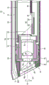
As shown in fig. 7 to 9, the grip 22 is formed in a substantially cylindrical shape (see fig. 3) in which a tip 207 on the X (+) direction side is open and a base 208 on the X (-) direction side is closed. A first flat surface portion 200, a second flat surface portion 202, a first curved surface portion 204, and a second curved surface portion 206 are formed on the outer surface of the grip portion 22.
The first planar portion 200 is formed on the outer surface of the grip 22 at a position on the Z (+) direction side, which is a position on the upper side in the up-down direction of the observation image 300 (up-down direction of the imaging system 61). The first plane portion 200 is a plane extending in the X direction and perpendicular to the Z direction, and is formed from the distal end portion 207 of the grip portion 22 to the base end portion 208. With the holding portion 22 held by the doctor, the root portion of the thumb of the doctor's hand is in contact with the first planar portion 200. The first plane portion 200 may be substantially parallel to the X direction or may be substantially perpendicular to the Z direction.
A first mark 226 is formed at the distal end portion of the first planar portion 200. The first mark 226 is located at the center of the first plane portion 200 in the Y direction when the first plane portion 200 is viewed from the Z (+) direction side. The shape of the first mark 226 is not particularly limited as long as it can be recognized by a tactile sensation based on the thumb or the like of the operator, and is formed in a convex shape, for example.
The second flat surface 202 is formed on the outer surface of the grip 22 at a position opposite to the first flat surface 200 with the insertion axis Ax interposed therebetween, that is, at a position on the lower side in the up-down direction (up-down direction of the imaging system 61) of the observation image 300, that is, at a position on the Z (-) direction side. The second plane 202 is a plane extending in the X direction and perpendicular to the Z direction, similarly to the first plane 200, but is formed from the front end 207 at a position immediately forward of the base end 208. When the holding portion 22 is held by the doctor, fingers of the doctor's hand other than the thumb are brought into contact with the second flat surface portion 202. The second plane 202 may be substantially parallel to the X direction or may be substantially perpendicular to the Z direction.
The first curved surface portion 204 is a curved surface connecting the side edge portion 200A on the Y (+) direction side of the first planar portion 200 and the side edge portion 202A on the Y (+) direction side of the second planar portion 202. The first curved surface 204 bulges toward the Y (+) direction. When the operator grips the grip 22 with, for example, the right hand, particularly the palm of the right hand, contacts the first curved surface portion 204.
The second curved surface portion 206 is a curved surface connecting the side edge portion 200B on the Y (-) direction side of the first planar portion 200 and the side edge portion 202B on the Y (-) direction side of the second planar portion 202. The second curved surface 206 bulges toward the Y (-) direction. When the operator grips the grip 22 with, for example, the right hand, the tip of the finger of the right hand other than the thumb is in contact with the second curved surface portion 206.
The base end 208 of the grip 22 is formed in a dome shape (also referred to as a shell shape) that bulges in the X (-) direction. When the holding portion 22 is held by the doctor, the base end 208 is in contact with the palm of the doctor.
Further, since the second flat surface portion 202 is formed to a position directly in front of the base end portion 208 as described above, a portion of the base end portion 208, that is, a portion on the Z (-) direction side becomes a bulge portion 208A bulging further toward the Z (-) direction side than the second flat surface portion 202. Then, an inclined plane portion 210 is provided between the bulge portion 208A and the second plane portion 202. The inclined plane portion 210 is an inclined plane inclined to the Z (-) direction side as it goes further to the X (-) direction side from the base end of the second plane portion 202. When the holding portion 22 is held by the doctor, the middle finger or the ring finger (or little finger) of the doctor's hand is brought into contact with the bulge 208A and the inclined plane portion 210.
The proximal end 208 has a substantially tubular cable insertion portion 73 protruding from a position offset from a proximal end apex P on the proximal end side thereof toward the Z (-) direction. When viewed from the Y direction side, the cable insertion portion 73 is inclined in an obliquely downward direction C from the base end portion 208 toward the X (-) direction side and toward the Z (-) direction side with respect to the X (-) direction. The external cable 72 is connected to the cable insertion portion 73. Thereby, the second signal cable 27 and the light guide 28 positioned inside the external cable 72 are inserted into the grip 22 through the cable insertion portion 73. As a result, the second signal cable 27 is connected to the first signal cable 26 inside the grip 22, and is further electrically connected to the imaging unit 60 via the first signal cable 26. The light emitting end 28C of the light guide 28 is disposed on the distal end side of the outer tube 30 through the light guide insertion space 70 and the space 31.
When the doctor holds the grip 22, the cable insertion portion 73 is abutted against the inside of the palm of the doctor. Thereby, the external cable 72 is led out from the root portion of the little finger of the operator's hand holding the grip 22.
A finger rest 220, finger contact portions 222 and 224, a second mark 228, and a third mark 230 are formed on the outer surface of the knob 36.
An abdomen portion of the thumb of the operator who grips the grip 22 is placed on the finger rest 220. The finger rest 220 is formed in a concave curved shape corresponding to the shape of the abdomen portion of the thumb.
The finger contact portions 222 and 224 are formed on the outer surface of the knob 36 so as to sandwich the finger rest 220 in the axial direction B. The finger contact portions 222 and 224 contact both side portions of the thumb placed on the finger rest 220. Thus, the operating force generated by the surgeon moving the thumb left and right can be effectively transmitted to the knob 36.
A second indicator 228 is provided on the finger rest 220. The shape of the second mark 228 is not particularly limited as long as it can be recognized by the thumb of the doctor, and is formed in a convex shape, for example. In the case where the rotational position of the knob 36 in the axial direction B is adjusted to the central position (intermediate position) of the rotational range of the knob 36, the second mark 228 is located on the same line as the first mark 226 formed on the first planar portion 200 in the X direction. Thus, the operator can easily grasp the center position of the knob 36 by the feeling of the finger. When the rotational position of the knob 36 is adjusted so that the second mark 228 matches the first mark 226, the viewing direction (observation direction, imaging direction) of the squint 10 includes a component in the Z (-) direction.
The third mark 230 is formed on the outer surface of the knob 36 at a position opposite to the position where the second mark 228 is formed with the insertion shaft Ax interposed therebetween. When the knob 36 is rotated in the axial direction B at a large angle (for example, 120 degrees) from the center position of the grip 22, the third mark 230 can be visually recognized even if the second mark 228 cannot be visually recognized. Accordingly, the rotational position of the knob 36 can be grasped based on the third mark 230.
Next, the operation of the squint mirror 10, particularly the operation unit 21, having the above-described configuration will be described.
In the case of performing observation or operation in the patient using the squint 10, the surgeon grips the grip 22 with the right hand (or the left hand), for example. In this case, the root portion of the thumb of the right hand is in contact with the first flat surface portion 200, the fingers of the right hand other than the thumb are in contact with the second flat surface portion 202, the inclined flat surface portion 210 and the bulge portion 208A, the palm of the right hand is in contact with the first curved surface portion 204 and the base end portion 208, the tip of the fingers of the right hand other than the thumb is in contact with the second curved surface portion 206, and the cable insertion portion 73 is in contact with the palm of the right hand. The external cable 72 is then derived from the root portion of the little finger of the right hand.
By placing the root portion of the thumb of the right hand of the operator on the first flat surface portion 200, the second flat surface portion 202 is easily supported by the other fingers of the right hand, and the operator can easily grasp the grip portion 22. When the surgeon places the thumb on the first flat surface portion 200 of the grip 22, the thumb can be placed on the finger rest 220 with the abdomen portion of the thumb naturally lying along the first flat surface portion 200. When the right palm is set up, the second flat surface 202 is formed on the outer surface of the grip 22, so that the grip 22 can be prevented from rolling on the right palm. Further, the base end 208 is brought into contact with the palm of the right hand, so that the stability of the holding portion 22 when held by the doctor can be improved.
Further, when the holding portion 22 is held by the doctor, the middle finger, ring finger, or the like of the right hand comes into contact with the inclined plane portion 210 and the bulge portion 208A, so that the stability of the holding portion 22 when held by the doctor can be further improved. Further, by forming the second flat surface portion 202 to a position on the front side of the base end portion 208 and providing the inclined flat surface portion 210 and the bulge portion 208A, the amount of the external cable 72 drawn out from the base end portion 208 can be ensured.
When the holding portion 22 is gripped by the doctor, the external cable 72 can be led out from the base end 208 in the obliquely downward direction C through the cable insertion portion 73. In the present embodiment, the occurrence of such a problem can be avoided, although the external cable 72 is brought into contact with the patient when the external cable 72 is led out from the base end portion 208 to the Z (-) direction side, or the external cable 72 is brought into contact with the doctor when the external cable 72 is led out from the base end portion 208 to the X (-) direction side.
As described above, the grip 22 of the present embodiment has an external shape that improves usability based on the ease with which the operator grips the grip 22 and the feeling of stability at the time of gripping. As a result, the grip 22 is prevented from rotating in the hand of the doctor, and thus the up-down direction of the observation image 300 is prevented from being changed.
After holding the grip 22, the operator inserts the insertion unit 20 into the patient, and confirms the observation image 300 output from the image pickup unit 60 via the display 16. Thereby, the physician can view the patient's body through the display 16. Then, when the doctor changes the viewing direction of the scope 10, the operator rotates the operation knob 36 in the axial direction B by the thumb of the right hand placed on the finger rest 220. Thus, the outer tube 30 and the outer tube 32 (the front end optical system 40) are rotated integrally with the knob 36 in the same direction, and the viewing direction of the squint mirror 10 can be oriented in a desired direction.
At this time, since the posture of the inner tube 34 in the axial direction B is maintained by the magnetic coupling 102, the inner tube 34 (the base end optical system 50 and the imaging unit 60) is prevented from rotating in the axial direction B together with the outer tube 32 (rotations). As a result, even if the viewing direction is changed, the rotation of the observation image 300 observed on the display 16 is prevented, and the vertical direction of the observation image 300 is maintained. In the operation unit 21 of the present embodiment, the knob 36 can be rotated by the right hand holding the grip unit 22, that is, the grip of the operation unit 21 and the rotation operation of the knob 36 can be performed by one hand. As a result, the operability of the squint mirror 10 is improved.
While the patient is being observed by the observation image 300 displayed on the display 16, the doctor grasps the up-down direction of the observation image 300 based on the first plane portion 200 and the second plane portion 202 on the outer surface of the grip portion 22. As described above, the first flat surface portion 200 is formed at a position on the upper side in the up-down direction of the observation image 300 and the second flat surface portion 202 is formed at a position on the lower side in the up-down direction of the observation image 300 in the outer surface of the grip portion 22. Therefore, the operator can grasp the vertical direction of the observation image 300 by the feeling of the right hand (finger) holding the grip 22 without looking away from the display 16. Thus, the doctor can adjust the posture of the grip 22 so that the vertical direction of the observation image 300 matches a desired direction such as the vertical direction of the display 16. As a result, the doctor can maintain the state in which the up-down direction of the observation image 300 coincides with the up-down direction of the display 16 during observation in the patient's body passing through the display 16, rotation operation of the knob 36, other operation, or operation.
As described above, in the present embodiment, the first flat surface portion 200 is formed at the outer surface of the grip 22 at the upper side in the up-down direction of the observation image 300, and the second flat surface portion 202 is formed at the lower side in the up-down direction of the observation image 300, so that the operator can easily grasp the up-down direction of the observation image 300.
Further, by setting the shape of the surfaces other than the first flat surface portion 200 and the second flat surface portion 202 to a curved surface shape, that is, a shape other than a flat surface, on the outer surface of the grip portion 22, the operator can easily grasp the first flat surface portion 200 and the second flat surface portion 202, that is, the up-down direction of the observation image 300, with only the feeling of the finger.
[ others ]
In the above embodiment, the insertion portion 20 is constituted by the outer tube 30, the outer tube 32, and the inner tube 34, and the structure of the insertion portion 20 is not particularly limited as long as the visual field direction can be changed according to the rotation operation of the knob 36.
In the above embodiment, the side edge portion 200A and the side edge portion 202A are connected by the first curved surface portion 204, and the side edge portion 200B and the side edge portion 202B are connected by the second curved surface portion 206, but if the doctor can recognize the first flat surface portion 200 and the second flat surface portion 202 by hand feeling, an arbitrary shape surface may be provided instead of the first curved surface portion 204 and the second curved surface portion 206.
In the above embodiment, the housing 74 is provided inside the grip 22, but the structure provided inside the grip 22 is not particularly limited.
In the above embodiment, the description has been made by taking as an example the rigid scope 10 in which the visual field direction can be changed, but the present invention can be applied to a rigid scope in which the visual field direction is fixed and an operation portion thereof. In this case, the knob 36 is omitted from the operation portion 21. The present invention is not limited to a hard scope, and can be applied to a soft scope (soft endoscope) and an operation unit thereof.
Symbol description
A tilt mirror, a 12-endoscope system, a 14-processor device, a 16-display, a 18-light source device, a 20-insertion section, a 21-operation section, a 22-grip section, a 24-unit, a 26-first signal cable, a 27-second signal cable, a 28-light guide, a 28C-light exit end, a 30-outer tube, a 31-space, a 32-outer tube, a 34-inner tube, a 36-knob, a 38-seal ring, a 40-front end optical system, a 42-front end body, a 44-front end lens barrel, a 45-cylindrical section, a 46-cover glass, a 48 a-objective lens, a 48 b-prism, a 48C-lens, a 50-base end optical system, a 52-base end lens barrel, a 54-bracket, and a 55-prism, 56-lens, 60-image pickup section, 61-image pickup system, 64-image pickup element, 66-circuit board, 68-connector, 70-light guide insertion space, 72-external cable, 73-cable insertion section, 74-housing, 74 a-partition, 74 b-cylindrical section, 80-airtight space, 82-airtight connector, 84-coupling section, 90-coupling section, 92-bearing support section, 94-bearing, 96-bearing support section, 98-bearing, 100-coupling beam, 100A-ring section, 100 b-ring section, 102-magnetic coupling, 103-first magnet, 104-second magnet, 120-rotation stopper, 200-first planar section, 200A-side edge section, 200B-side edge portion, 202-second flat portion, 202A-side edge portion, 202B-side edge portion, 204-first curved portion, 206-second curved portion, 207-front end portion, 208-base end portion, 208A-bulge portion, 210-inclined flat portion, 220-finger rest portion, 222-finger abutment portion, 224-finger abutment portion, 226-first mark, 228-second mark, 230-third mark, 300-observation image, ax-insertion axis, B-axis direction, C-obliquely downward direction, OA-optical axis, P-base end apex.
Claims (12)
1. An operation unit connected to a proximal end side of an insertion unit of an endoscope, the insertion unit being provided with an optical system and an imaging unit that images light passing through the optical system, the operation unit comprising:
a grip portion extending in an axial direction of an insertion shaft of the insertion portion;
a first plane portion formed on an outer surface of the grip portion at a position on an upper side in the vertical direction, and extending in the axial direction and being perpendicular to the vertical direction, when a vertical direction indicating an image formed based on an imaging signal output from the imaging portion is set as the vertical direction; a kind of electronic device with high-pressure air-conditioning system
And a second flat surface portion formed on an outer surface of the grip portion at a position indicating a lower side in the up-down direction, extending in the axial direction and being perpendicular to the up-down direction.
2. The operation section according to claim 1, wherein,
the grip portion includes:
a first curved surface portion that, when a direction perpendicular to both the axial direction and the vertical direction is a vertical direction, connects a side edge portion on one side of the vertical direction of the first planar portion and a side edge portion on one side of the vertical direction of the second planar portion, and bulges toward one side of the vertical direction; a kind of electronic device with high-pressure air-conditioning system
And a second curved surface portion that connects a side edge portion on the other side in the vertical direction of the first planar portion and a side edge portion on the other side in the vertical direction of the second planar portion, and bulges toward the other side in the vertical direction.
3. The operation section according to claim 1 or 2, wherein,
the base end portion of the grip portion is formed in a dome shape.
4. The operation portion according to any one of claims 1 to 3, wherein,
the first plane part is formed from the front end part of the holding part to the base end part of the holding part,
the second flat portion is formed from the distal end portion of the grip portion over a position on the front side of the proximal end portion of the grip portion,
a part of the base end portion of the grip portion is a bulge portion bulging downward in the up-down direction than the second planar portion.
5. The operation section according to claim 4, wherein,
the operation unit includes:
and an inclined plane portion which is provided between the base end of the second plane portion and the bulge portion in a connecting manner and which is inclined downward in the vertical direction as going further toward the base end side from the base end of the second plane portion.
6. The operation portion according to any one of claims 1 to 5, wherein,
The operation unit includes:
a cable insertion portion protruding from a base end apex of the base end portion of the grip portion to a position offset to a lower side in the up-down direction for inserting a cable connected to the imaging portion,
the cable insertion portion is provided so as to protrude in a direction on a base end side of a base end portion of the grip portion when viewed from a vertical direction perpendicular to both the axial direction and the vertical direction, and is provided so as to protrude in a direction inclined to a lower side of the vertical direction with respect to the axial direction.
7. The operation portion according to any one of claims 1 to 6, wherein,
the insertion portion includes:
an outer tube which is held rotatably relative to the distal end side of the grip portion in the axial direction of the insertion shaft;
an outer tube inserted into the outer tube and rotated integrally with the outer tube in the axial direction; a kind of electronic device with high-pressure air-conditioning system
An inner tube inserted into the outer tube and rotatable relative to the outer tube and the outer tube in the axial direction,
when the optical system is provided on the distal end side of the outer tube and the imaging unit is provided on the distal end side of the inner tube, the optical system is provided with:
An inner tube fixing portion provided inside the grip portion so as not to be rotatable relative to the grip portion in the axial direction, to fix a base end side of the inner tube; a kind of electronic device with high-pressure air-conditioning system
And an annular rotation operation member fixed to a base end side of the outer tube, and configured to rotate the outer tube in the axial direction.
8. The operation portion according to any one of claims 1 to 7, wherein,
the grip portion is made of a rubber material or a resin material.
9. An endoscope, comprising:
an insertion section provided with an optical system and an imaging section for imaging light passing through the optical system; a kind of electronic device with high-pressure air-conditioning system
The operation portion according to any one of claims 1 to 8 connected to a base end side of the insertion portion.
10. The endoscope of claim 9, wherein,
the insertion portion includes:
an outer tube which is held rotatably relative to the distal end side of the grip portion in the axial direction of the insertion shaft;
an outer tube inserted into the outer tube and rotated integrally with the outer tube in the axial direction;
an inner tube inserted into the outer tube and rotatable relative to the outer tube and the outer tube in the axial direction; a kind of electronic device with high-pressure air-conditioning system
An inner tube fixing portion provided in the grip portion so as not to be rotatable relative to the grip portion in the axial direction, for fixing a base end side of the inner tube,
the optical system is provided on the front end side of the outer tube,
the imaging unit is provided on the distal end side of the inner tube.
11. The endoscope of claim 10, wherein,
the endoscope is provided with:
and an annular rotation operation member fixed to a base end side of the outer tube, and configured to rotate the outer tube in the axial direction.
12. The endoscope according to any one of claims 9 to 11, wherein,
the optical system includes a refractive optical element that refracts light incident from a direction inclined with respect to the insertion axis in parallel with the insertion axis.
Applications Claiming Priority (2)
| Application Number | Priority Date | Filing Date | Title |
|---|---|---|---|
| JP2021194571A JP2023080970A (en) | 2021-11-30 | 2021-11-30 | Operation part and endoscope |
| JP2021-194571 | 2021-11-30 |
Publications (1)
| Publication Number | Publication Date |
|---|---|
| CN116195954A true CN116195954A (en) | 2023-06-02 |
Family
ID=86316920
Family Applications (1)
| Application Number | Title | Priority Date | Filing Date |
|---|---|---|---|
| CN202211430262.2A Pending CN116195954A (en) | 2021-11-30 | 2022-11-15 | Operation unit and endoscope |
Country Status (4)
| Country | Link |
|---|---|
| US (1) | US20230165435A1 (en) |
| JP (1) | JP2023080970A (en) |
| CN (1) | CN116195954A (en) |
| DE (1) | DE102022131736A1 (en) |
Family Cites Families (4)
| Publication number | Priority date | Publication date | Assignee | Title |
|---|---|---|---|---|
| US5621830A (en) | 1995-06-07 | 1997-04-15 | Smith & Nephew Dyonics Inc. | Rotatable fiber optic joint |
| DE102016212470A1 (en) | 2016-07-08 | 2018-01-11 | Olympus Winter & Ibe Gmbh | Optical system of a stereo video endoscope, stereo video endoscope and method of operating an optical system of a stereo video endoscope |
| JP6889158B2 (en) | 2017-08-31 | 2021-06-18 | 富士フイルム株式会社 | Endoscope connector device |
| DE102018100481A1 (en) | 2018-01-10 | 2019-07-11 | Olympus Winter & Ibe Gmbh | Videoscope |
-
2021
- 2021-11-30 JP JP2021194571A patent/JP2023080970A/en active Pending
-
2022
- 2022-11-15 CN CN202211430262.2A patent/CN116195954A/en active Pending
- 2022-11-18 US US18/057,151 patent/US20230165435A1/en active Pending
- 2022-11-30 DE DE102022131736.6A patent/DE102022131736A1/en active Pending
Also Published As
| Publication number | Publication date |
|---|---|
| JP2023080970A (en) | 2023-06-09 |
| US20230165435A1 (en) | 2023-06-01 |
| DE102022131736A1 (en) | 2023-06-01 |
Similar Documents
| Publication | Publication Date | Title |
|---|---|---|
| US10206559B2 (en) | Endoscope apparatus | |
| JP5132018B2 (en) | Zoom laparoscope | |
| US7662092B2 (en) | Endoscope device with electrically actuated bending | |
| EP1736094B1 (en) | Endoscope device | |
| US8100825B2 (en) | Endoscope and supportive member for bending operation of the same | |
| JP2006015078A (en) | Medical apparatus | |
| JP2001095747A (en) | Electronic endoscope | |
| US20140012087A1 (en) | Endoscope | |
| WO2006052769A1 (en) | Endoscope with independently rotatable tube and eyepiece | |
| JP4648638B2 (en) | Endoscope | |
| JP6322775B1 (en) | Endoscope system | |
| JP6116780B1 (en) | Endoscope | |
| US20140066710A1 (en) | Devices and methods for intraoperative control of endoscopic imaging | |
| JP4847071B2 (en) | Endoscopic imaging device | |
| CN116195954A (en) | Operation unit and endoscope | |
| US20230165437A1 (en) | Endoscope | |
| JP7264162B2 (en) | Interchangeable lens, imaging device and rotation detection device | |
| JPH0713087A (en) | Hard endoscope device | |
| JP2002058629A (en) | Electronic endoscope | |
| US11350816B2 (en) | Portable and ergonomic endoscope with disposable cannula | |
| CN113329675B (en) | Endoscope with a lens | |
| US20240090922A1 (en) | Miniature Angle-View Endoscope with Image Orientation Correction | |
| EP3858216B1 (en) | Endoscope | |
| JP6173624B1 (en) | Endoscope | |
| CN115886694A (en) | Endoscope with a detachable handle |
Legal Events
| Date | Code | Title | Description |
|---|---|---|---|
| PB01 | Publication | ||
| PB01 | Publication |