CN116194675A - Flow control structure for enhanced performance and turbine incorporating the same - Google Patents
Flow control structure for enhanced performance and turbine incorporating the same Download PDFInfo
- Publication number
- CN116194675A CN116194675A CN202180063581.1A CN202180063581A CN116194675A CN 116194675 A CN116194675 A CN 116194675A CN 202180063581 A CN202180063581 A CN 202180063581A CN 116194675 A CN116194675 A CN 116194675A
- Authority
- CN
- China
- Prior art keywords
- channels
- channel
- turbine
- diffuser
- angle
- Prior art date
- Legal status (The legal status is an assumption and is not a legal conclusion. Google has not performed a legal analysis and makes no representation as to the accuracy of the status listed.)
- Pending
Links
Images


Classifications
-
- F—MECHANICAL ENGINEERING; LIGHTING; HEATING; WEAPONS; BLASTING
- F01—MACHINES OR ENGINES IN GENERAL; ENGINE PLANTS IN GENERAL; STEAM ENGINES
- F01D—NON-POSITIVE DISPLACEMENT MACHINES OR ENGINES, e.g. STEAM TURBINES
- F01D25/00—Component parts, details, or accessories, not provided for in, or of interest apart from, other groups
- F01D25/24—Casings; Casing parts, e.g. diaphragms, casing fastenings
-
- F—MECHANICAL ENGINEERING; LIGHTING; HEATING; WEAPONS; BLASTING
- F01—MACHINES OR ENGINES IN GENERAL; ENGINE PLANTS IN GENERAL; STEAM ENGINES
- F01D—NON-POSITIVE DISPLACEMENT MACHINES OR ENGINES, e.g. STEAM TURBINES
- F01D9/00—Stators
- F01D9/02—Nozzles; Nozzle boxes; Stator blades; Guide conduits, e.g. individual nozzles
- F01D9/04—Nozzles; Nozzle boxes; Stator blades; Guide conduits, e.g. individual nozzles forming ring or sector
- F01D9/045—Nozzles; Nozzle boxes; Stator blades; Guide conduits, e.g. individual nozzles forming ring or sector for radial flow machines or engines
-
- F—MECHANICAL ENGINEERING; LIGHTING; HEATING; WEAPONS; BLASTING
- F01—MACHINES OR ENGINES IN GENERAL; ENGINE PLANTS IN GENERAL; STEAM ENGINES
- F01D—NON-POSITIVE DISPLACEMENT MACHINES OR ENGINES, e.g. STEAM TURBINES
- F01D11/00—Preventing or minimising internal leakage of working-fluid, e.g. between stages
- F01D11/08—Preventing or minimising internal leakage of working-fluid, e.g. between stages for sealing space between rotor blade tips and stator
-
- F—MECHANICAL ENGINEERING; LIGHTING; HEATING; WEAPONS; BLASTING
- F04—POSITIVE - DISPLACEMENT MACHINES FOR LIQUIDS; PUMPS FOR LIQUIDS OR ELASTIC FLUIDS
- F04D—NON-POSITIVE-DISPLACEMENT PUMPS
- F04D17/00—Radial-flow pumps, e.g. centrifugal pumps; Helico-centrifugal pumps
- F04D17/08—Centrifugal pumps
- F04D17/10—Centrifugal pumps for compressing or evacuating
-
- F—MECHANICAL ENGINEERING; LIGHTING; HEATING; WEAPONS; BLASTING
- F04—POSITIVE - DISPLACEMENT MACHINES FOR LIQUIDS; PUMPS FOR LIQUIDS OR ELASTIC FLUIDS
- F04D—NON-POSITIVE-DISPLACEMENT PUMPS
- F04D29/00—Details, component parts, or accessories
- F04D29/40—Casings; Connections of working fluid
- F04D29/42—Casings; Connections of working fluid for radial or helico-centrifugal pumps
- F04D29/44—Fluid-guiding means, e.g. diffusers
- F04D29/441—Fluid-guiding means, e.g. diffusers especially adapted for elastic fluid pumps
- F04D29/444—Bladed diffusers
-
- F—MECHANICAL ENGINEERING; LIGHTING; HEATING; WEAPONS; BLASTING
- F05—INDEXING SCHEMES RELATING TO ENGINES OR PUMPS IN VARIOUS SUBCLASSES OF CLASSES F01-F04
- F05D—INDEXING SCHEME FOR ASPECTS RELATING TO NON-POSITIVE-DISPLACEMENT MACHINES OR ENGINES, GAS-TURBINES OR JET-PROPULSION PLANTS
- F05D2250/00—Geometry
- F05D2250/20—Three-dimensional
- F05D2250/29—Three-dimensional machined; miscellaneous
- F05D2250/294—Three-dimensional machined; miscellaneous grooved
Abstract
A flow control device and structure for a turbine. In some examples, the flow control devices and structures include various arrangements of flow guide channels, partial-height vanes, and other treatments on one or both of the shroud side and the hub side of the turbine to redirect, guide, or otherwise affect portions of the turbine flow field, thereby improving machine performance.
Description
Cross Reference to Related Applications
The present application claims the benefit of priority from U.S. provisional patent application serial No. 62/706,286, filed 8/7 in 2020, entitled "Enhanced Performance Imbedded Diffuser Passages and Grooved Turbomachinery Impeller Covers (enhanced performance embedded diffuser channel and slotted turbine wheel cover)", which is incorporated herein by reference in its entirety.
Technical Field
The present disclosure relates generally to the field of turbines. In particular, the present disclosure relates to a flow control structure for enhanced performance and a turbine incorporating the flow control structure.
Background
The losses of the turbine stages vary from case to case in terms of strength and characteristics, but all turbine stages include most of the mechanisms in the following for single-phase, single-component streams: surface friction, secondary flow generation, outlet mixing, interstitial gap flow, leakage, and impingement formation for highly compressible flows. These mechanisms are in turn affected by a number of design parameters such as flow, inlet pressure and temperature, outlet pressure, angle of incidence, flow turning plus surface curvature, thickness and rotation regime, etc. Losses negatively affect turbine performance and are generally understood as degradation of flow conditions, resulting in a decrease in the overall pressure and an increase in entropy of the flow process. Losses can also lead to flow separation and stall and impeller slippage, as well as non-uniform flow fields, which often negatively impact downstream element performance. There remains a need for improved apparatus and methods for reducing losses and mitigating the effects of losses.
Disclosure of Invention
In one implementation, the present disclosure relates to a turbine. The turbine includes a hub surface, a shroud surface, and a plurality of recessed channels in the hub surface or shroud surface, each of the recessed channels extending in a flow direction and having an angular profile α (M) relative to a meridian reference plane passing through the corresponding channel at a meridian location M along the channel length; and wherein the angle of at least a first portion of each of the channels is designed and configured to be equal to or less than the calculated minimum flow angle of the working fluid at the maximum mass flow rate operating point, thereby increasing the coupling of the channel to the working fluid at the maximum mass flow rate operating point.
In another implementation, the present disclosure is directed to a turbine. The turbine includes a hub surface, a shroud surface, and a plurality of recessed channels extending in a flow direction and located in the hub surface or the shroud surface; and wherein the plurality of channels comprises a plurality of first channels and a plurality of second channels, wherein an angle α1 (M) of the first channels relative to a meridian location along the channels is different from an angle α1 (M) of the second channels relative to a meridian location along the channels, wherein the angles α1 (M), α1 (M) are angles of a corresponding one of the first channels or the second channels relative to a meridian reference plane passing through the channels at the meridian location M along the channel length.
In yet another implementation, the present disclosure is directed to a turbine. The turbine includes a hub surface, a shroud surface, and a plurality of recessed channels extending in a flow direction and located in the hub surface or shroud surface, each of the channels having a first edge on a convex side of the channel and a second edge on a concave side of the channel at the hub surface or shroud surface; and wherein at least a portion of at least one of the first edge and the second edge of at least one of the plurality of channels includes a tip forming a scoop to capture and redirect flow into the channel.
In yet another implementation, the present disclosure is directed to a turbine. The turbine includes a hub surface, a shroud surface, a plurality of recessed channels extending in a flow direction and located in the hub surface or shroud surface, and a plurality of partial-height blades positioned adjacent corresponding ones of the recessed channels, the partial-height blades being designed and configured to improve coupling of the recessed channels to a working fluid flow field.
In yet another implementation, the present disclosure is directed to a method of forming a flow control structure for a turbine having an impeller, a shroud, a hub, and downstream elements. The method includes estimating a change in flow angle of a working fluid near a hub or shroud as a function of mass flow rate in a flow field distribution of a turbine; identifying an estimated minimum flow angle at a maximum mass flow rate operating point; and defining at least one channel in a surface of the hub or the shroud for redirecting at least a portion of the working fluid, the defining including selecting a channel angle of the at least one channel that is less than or equal to the estimated minimum flow angle, thereby improving coupling of the at least one channel to the working fluid at the maximum mass flow rate operating point.
In yet another implementation, the present disclosure is directed to a method of defining a flow control structure for a turbine having an impeller with an inlet and an outlet, a shroud, a hub, and a downstream element, the hub and shroud defining an impeller passageway, the method comprising generating a computational fluid model of the turbine using a computer; calculating an impeller passageway flow field distribution at the maximum mass flow rate operating point using the calculated fluid model; determining a change in flow angle in a flow field distribution near the hub or shroud; and defining at least one passage extending in the flow direction in at least one of the hub and the shroud, the defining including defining a passage angle of the at least one passage that is less than or equal to the determined flow angle at the maximum mass flow rate operating point.
Drawings
For the purpose of illustrating the disclosure, the drawings show aspects of one or more embodiments of the disclosure. However, it should be understood that the present disclosure is not limited to the precise arrangements and instrumentalities shown in the drawings, wherein:
FIG. 1 is a cross-sectional side view of a radial compressor having recessed channels in a hub surface and shroud surface of the compressor;
FIG. 2 is a front view of a diffuser backplate of the compressor of FIG. 1;
FIG. 3 shows measured performance of three different vaneless diffusers coupled to compressors;
FIG. 4 shows measured performance of three different vaneless diffusers coupled to compressors;
FIG. 5 illustrates calculated average flow angles as a function of meridional position for flow tubes adjacent a shroud surface in a centrifugal compressor coupled to a vaneless diffuser;
FIG. 6 shows calculated average flow angle as a function of meridian position for flow tubes adjacent a hub surface in a centrifugal compressor coupled to a vaneless diffuser;
FIG. 7 illustrates calculated average flow angles as a function of meridional position for flow tubes adjacent to shroud surfaces in a centrifugal compressor coupled to a vaneless diffuser;
FIG. 8 shows calculated average flow angle as a function of meridian position for flow tubes adjacent a hub surface in a centrifugal compressor coupled to a vaneless diffuser;
FIG. 9 illustrates calculated average flow angles as a function of meridional position for flow tubes adjacent a shroud surface in a centrifugal compressor coupled to a vaneless diffuser;
FIG. 10 shows an example flow chart generated by the CFD program for a flow rate of 0.5lbm/sec, 100000rpm, shroud side case and showing a portion of the impeller and diffuser;
FIG. 11 illustrates a portion of a diffuser backplate and also conceptually illustrates two example flow streamlines at different flow angles;
FIG. 12 illustrates a diffuser plate including multiple sets of channels with different channel angles;
FIG. 13 shows a front view of the diffuser plate of FIG. 12;
FIG. 14 illustrates another example of a diffuser plate including multiple sets of channels with different channel angles;
FIG. 15 illustrates another example of a diffuser plate including multiple sets of channels with different channel angles;
FIG. 16 illustrates another example of a diffuser plate including multiple sets of channels with different channel angles;
FIG. 17 illustrates a diffuser plate with two sets of channels and also conceptually illustrates low angle streamlines and high angle streamlines;
18-20 illustrate example transition edge features that may be incorporated into recessed channels;
FIG. 21 is a perspective view of a diffuser having partial height vanes positioned adjacent a plurality of recessed channels;
FIG. 22 is a top view of the diffuser of FIG. 21;
FIG. 23 is a side cross-sectional view of a portion of the diffuser of FIG. 21;
FIG. 24 is a side cross-sectional view of a portion of another example of a diffuser having partial-height vanes positioned adjacent a plurality of recessed channels;
FIG. 25 is a top view of a diffuser having partial-height vanes positioned adjacent a plurality of recessed channels;
FIG. 26 is a side cross-sectional view of a portion of the diffuser of FIG. 25;
FIG. 27 is a side cross-sectional view of a portion of another example of a diffuser having partial-height vanes positioned adjacent a plurality of recessed channels; and
FIG. 28 illustrates another example implementation of a diffuser including a plurality of recessed channels, at least some of the recessed channels having a cross-sectional area that varies along the length of the channels to form a converging-diverging nozzle.
Detailed Description
Aspects of the present disclosure include flow control devices and structures designed and configured to one or more of the following: reducing the negative impact of losses on the performance of the turbine, improving the performance of the turbine, reducing the negative impact of losses on downstream elements formed in upstream elements, and improving the coupling and performance of the upstream and downstream elements. As described more below, exemplary flow control devices made in accordance with the present disclosure may include various arrangements of flow guide channels, partial height vanes, and other treatments that may be located on one or both of the shroud side and the hub side of the turbine to redirect, guide, or otherwise affect portions of the turbine flow field, thereby improving machine performance.
Turbines, whether radial, axial or mixed flow, and whether compressors, pumps, turbines, etc., typically include an impeller having a plurality of blades and rotating about a rotational axis and disposed within a fluid path. The term "impeller" as used herein refers to any type of vaned impeller or rotor of any type of turbine, including compressors, turbines, pumps and fans. The turbine wheel has an inlet and an outlet and is typically in fluid communication with a downstream element such as a diffuser or cascade or nozzle or stator. Non-uniformities are created in the impeller flow field due to real world effects such as losses due to surface friction, interstitial gap flow, leakage, and eddy currents due to the fundamental nature of the rotating machine. Such non-uniformities may be described in terms of magnitude and angular non-uniformities of fluid velocity in the impeller passageway, wherein the low-loss regions of the flow field are generally aligned in a first direction, e.g., following the impeller channel direction, and other regions of the flow field are conveyed at various other angles and velocities, up to and including perpendicular to the main impeller channel direction and in the opposite direction of the main impeller passageway direction. Such off-angle flow field non-uniformities represent losses in the system and may lead to further losses such as flow instability, stall in downstream elements, backflow in the impeller, or large impeller outlet aerodynamic blockage. The term "primary flow" and similar terms generally refer to the low loss portion of the impeller flow field that is generally aligned with the passage direction, and "secondary flow" and similar terms generally refer to other portions of the working fluid flow field, and which may contain eddy currents and appreciable losses.
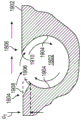
Fig. 1 and 2 illustrate one example of a centrifugal compressor 100 including a flow control structure made in accordance with the present disclosure. FIG. 1 is a cross-sectional side view and illustrates an impeller 102 rotatably disposed within an impeller shroud 164 and upstream of a vaneless diffuser 106. Impeller 102 is configured to rotate about an axis of rotation a1 and includes a plurality of blades 108 (only one labeled), and an inlet 112 and an outlet 114. The impeller blades 108 extend in a meridional direction between a leading edge 116 (only one marked) and a trailing edge 118 (only one marked) and in a spanwise direction between a hub 120 and shroud sides 122 of the impeller blades. The shroud 164 (also sometimes referred to as a housing) extends from the impeller inlet 112 to the outlet 114 and defines a shroud surface 124 positioned adjacent the shroud sides 122 of the impeller blades, the shroud 164 defining an impeller passageway with the hub 120.
As is known in the art, the impeller 102 is configured to deliver a working fluid through an impeller passageway, compress the working fluid, and discharge the compressed working fluid through a diffuser 106. The diffuser 106 includes a front plate 125 defining a front surface 126 (sometimes referred to as a shroud surface or shroud side of the diffuser) and a back plate 128 defining a back surface 130 (sometimes referred to as a hub surface or hub side of the diffuser). The shroud surface 124 of the shroud 164 and the diffuser front surface 126 are generally aligned, and the portion of the hub 120 at the impeller outlet 114 is aligned with the diffuser rear surface 130 as shown. In the illustrated example, the impeller 102 is open such that there is a small gap between the shroud side 122 of the blades 108 and the shroud surface 124, and the impeller is configured to rotate relative to the stationary shroud 164. Similarly, there is a small gap between the hub outer radius 134 and the diffuser backplate 128, while the shroud 164 and the diffuser front plate 125 may not include any such gap and may form a continuous surface between the impeller and the diffuser 106.
FIG. 2 is a front view of the back plate 128 of the diffuser with the remaining components of the compressor 100 omitted. As shown in fig. 2, the back plate 128 of the diffuser includes a plurality of elongated flow guide channels 202 (only one labeled), the flow guide channels 202 being positioned circumferentially around the back plate and extending generally in the flow direction from the diffuser inlet 204 to the diffuser outlet 206. The channels 202 have a meridian length defined as the length of the channel centerline extending from the beginning to the end of a given channel. In other examples, the channels 202 may have different lengths, e.g., the channels 202 may not extend to the diffuser outlet 206 and may end upstream of the diffuser outlet. In some examples, the channel 202 may be designed and configured to communicate with a flow direction channel (not shown) located in the impeller hub 120.
The curvature of the channel 202 may be characterized by an angular profile α (M) defining the angle of the channel relative to a meridian position M along the length of the channel when projected onto the meridian reference plane MP, the angle α being the angle between a tangent t to the channel centerline and the meridian reference plane MP passing through the impeller rotation axis a1, the meridian reference plane MP intersecting the channel at the meridian position M. Fig. 2 shows an angle α1 at a meridian position M1 with respect to a meridian reference plane MP1 extending through the tunnel at the meridian position M1, and an angle α2 at a meridian position M2 with respect to a meridian reference plane MP2 extending through the tunnel at the meridian position M2. The flow directing channels disclosed herein may have an angle α (M) that varies along the length of the channel or have a constant angle. In the illustrated example, the channel 202 has a constant angle α (M). As shown in fig. 2, in a radial machine such as compressor 100, the channel having a constant angle α (M) has a curved spiral shape.
The channel 202 has a flow direction length, defined as the length of the channel centerline extending from the beginning to the end of a given channel, and has a chord length c, defined as the length of the chord line CL. In the illustrated example, the channels 202 are disposed around the circumference of the diffuser 106 and are evenly spaced apart. Channel solidity (solidity) may be defined as the ratio between the chord length c and the spacing s between adjacent channels, e.g. the spacing of diffuser inlets or any other common reference point. The channel 202 is designed and configured to direct a portion of the working fluid, such as the secondary flow portion of the working fluid, to reduce losses and provide diffuser and compressor performance.
Referring again to fig. 1, the compressor 100 also includes a plurality of elongated flow guide channels 140 (only one shown) on the shroud side of the compressor. In the illustrated example, the channel 140 extends from a start location 142 in the impeller passageway upstream of the impeller blade trailing edge 118 and generally extends in the flow direction downstream beyond the impeller outlet 114 and into the diffuser 106 along the front surface 126 of the diffuser front plate 125 up to the diffuser outlet 114. The channels 140 in the front plate 125 may have a similar configuration as the channels 202 in the back plate 128, but may have a different number of channels, channel angles, cross-sectional shapes or sizes to account for differences in flow field characteristics between the hub and shroud surfaces. In other examples, the channels 140 may have different starting or ending positions, including starting positions located anywhere along the impeller passageway between the impeller inlet 112 and the outlet 114, or starting positions of one or more of the channels 140 may be located in the diffuser 106 and not in the impeller at all. The end positions of the channels 202 and 140 may similarly have any of a number of positions along the impeller length or diffuser passageway. In other examples, compressor 100 may include recessed flow direction channels only along the shroud side of the machine (e.g., only channels 140) and no channels along the hub side of the machine (e.g., no channels 202), or vice versa (only hub side channels and no shroud side channels).
Various examples of prior art flow directing channels are disclosed in U.S. patent No. 9,845,810 (the' 810 patent), entitled "Flow Control Structures for Turbomachines and Methods of Designing the Same (flow control structure for a turbine and method of designing the same), the contents of which are incorporated herein by reference in their entirety. Various features and combinations of flow directing structures including recessed flow directing channels may be combined with features described and illustrated in this disclosure.
Recent studies by the inventors have shown that the angle α (M) of flow direction channels, such as channels 202 and 140, can have a significant impact on the performance of the turbine. In some examples, to achieve desired performance characteristics, such as target pressure and flow characteristics, the flow direction curvature or flow direction angle profile of one or more of the channels may be set to approximate an estimated, measured, or calculated working fluid flow angle, for example, a flow angle at a particular meridian and span location in the machine when the turbine is operating at a particular operating point, such as at a stage choke point. For example, one or more recessed flow direction channels, such as channel 202 and/or channel 140, may have an angle α (M) along the entire length of the channel or along a portion of the channel that is about equal to, or in some examples about equal to or less than, the flow angle of the working fluid near the shroud wall surface or hub wall surface when the turbine is operating at the stage choke point. In some examples, the one or more passages may have an angle α (M) that is approximately equal to or less than the flow angle of the working fluid at or near the shroud wall surface when the turbine is operating at a mass flow rate of: the mass flow rate is at least 90% of the mass flow rate at the stage choke point, and in some examples, the mass flow rate is at least 80% of the mass flow rate at the stage choke point, and in some examples, the mass flow rate is at least 70% of the mass flow rate at the stage choke point, and in some examples, the mass flow rate is at least 60% of the mass flow rate at the stage choke point. In some examples, the one or more passages may have an angle α (M) that is approximately equal to or less than the flow angle of the working fluid at or near the shroud wall surface when the turbine is operating at a mass flow rate of: +/-15% of the mass flow rate at the optimal efficiency point, +/-15% of the mass flow rate at the choke point, such as a stage choke point, 20% to 80% of the mass flow rate at the optimal efficiency point, 20% to 80% of the mass flow rate at the choke point, the mass flow rate between the optimal efficiency point and the choke point, for example, about midway between the optimal efficiency point and the choke point.
As described more below, in some examples, more than one set of channels with different angular profiles may be included on the hub side or shroud side of the turbine to optimize performance over a wide range of operating conditions. In yet another example, the solidity of the channel may be selected to optimize performance. In yet another example, edge features along the length of the channel may be utilized to improve the effectiveness of the channel. In yet another example, vanes, such as full or partial height vanes, may be included to improve the performance of the recessed flow direction channel. In yet another example, the cross-sectional area may be configured and dimensioned to prevent obstruction in the channel.
Fig. 3 and 4 show measured performance of three different vaneless diffusers coupled to compressors: (1) Curve 302 represents test data from a baseline vaneless diffuser that does not include recessed channels in the hub or shroud; (2) Curve 304 represents test data from a vaneless diffuser similar to diffuser 106 and including recessed flow direction channels in both the front and back plates of the diffuser, similar to channels 202 and 140, but which do not extend into the impeller upstream of the diffuser; and (3) curve 306 represents test data from a diffuser that is identical to the diffuser of curve 304 except that the hub and shroud channels are circumferentially offset from each other and the shroud side channels are also similar to channel 140 and extend upstream into the impeller.
Fig. 3 illustrates total pressure-to-static pressure ratios relative to dimensionless mass flow rates for four different impeller speeds (80000 RPM to 135000 RPM). Fig. 4 illustrates the total efficiency versus static efficiency with respect to dimensionless mass flow rate for the same four impeller speeds (80000 RPM to 135000 RPM). As shown in fig. 3 and 4, at low flow rates, the performance of the machine including the flow direction channels (curves 304 and 306) is significantly better than the performance of the baseline machine without channels (curve 302), thus achieving high level performance of the original record. However, at higher flow rates at high speeds, there is a performance degradation 308, where the pressure and efficiency of the two machines with channels (curves 304 and 306) are about the same as the performance of the baseline case (curve 302). In other words, the performance benefits of the recessed flow direction channels appear to be lost at higher flow rates (above about mref=0.5) and higher speeds (125 k and 135k speed lines) and/or the channels appear to be less effective in improving machine performance. This trend is found whether operating from high flow to low flow (i.e., right to left on the line) or vice versa. Depending on the direction of operation, small changes in mass flow rate are observed, with performance degradation 308 occurring in the 120k and 135k velocity lines. The present disclosure includes the following structures: the structure is designed and configured to minimize or eliminate the observed performance degradation 308 and to provide a flow control structure including recessed flow direction channels designed to provide improved performance at high flow rates and speeds and at lower flow rates and speeds. As discussed more below, performance degradation at higher flow rates may be due to a reduced degree of coupling between the working fluid in the diffuser and the recessed channels, wherein changes in the working fluid flow angle cause portions of the working fluid to bypass the channels, resulting in reduced compressor performance and efficiency. In some cases, the decrease in performance may also be caused by a choked flow in one or more of the recessed channels at higher flow rates.
Fig. 5 shows calculated average flow angles as a function of meridian position for flow tubes adjacent to shroud surfaces in a centrifugal compressor coupled to a vaneless diffuser. The calculations were performed by computational fluid dynamics models of centrifugal compressors and vaneless diffusers. The concave flow direction channels are not included in the model. The average value of the flow angle is calculated in the circumferential direction around the machine, so that the variation between all impeller blades is averaged to one representative angle. Fig. 5 shows the average flow angle versus meridian position for four different mass flow rates each using an impeller operating at 135000RPM, where curve 502 illustrates the calculated flow angle for the lowest mass flow condition and curve 506 illustrates the angle for the highest mass flow condition. The angle is obtained in the same way as the angle α (M) with respect to the meridian reference plane. Thus, higher angles relative to the radial reference line indicate more tangential flow, which is well known in the art to be near the stability limit, and lower angles indicate more radial flow. In this figure, the impeller starts at about 25% meridian distance (M) and ends at about 62% meridian distance. The diffuser extends from about 62% meridian distance to about 88% meridian distance. Curve 502 is for the lowest flow rate condition and occurs immediately prior to stage stall or system surge; curve 506 is the lowest trace for the highest flow rate and occurs immediately before the impeller's choking limit level. These traces are obtained near the adjacent wall (cover); for the shroud, the trace passes just through the impeller clearance gap grid. As is evident from fig. 5, the flow angle becomes more radial (lower angle) as the mass flow rate increases. As noted above in connection with fig. 3 and 4, performance degradation is also observed at higher flow rates. Thus, as described in more detail below, decreasing the flow angle with increasing flow rate may cause the flow to eventually become more radial than the recessed channels, thereby preventing flow from entering the channels and reducing the impact of the channels on machine performance.
Fig. 6 shows calculated circumferential average flow angles along the hub for the same CFD model as used in fig. 5 and the same four operating conditions as shown in fig. 5, where curve 608 is the lowest flow condition and curve 606 is the highest flow condition. Fig. 7 and 8 illustrate calculated flow angle data along the shroud (fig. 7) and hub (fig. 8) as a function of meridian position and flow rate at a lower impeller speed of 100000 RPM. At lower rotational speeds, along the shroud (fig. 7), the diffuser time average (variation between blades) flow angle is in the range of 40 to 73 degrees relative to the meridian or radial direction, and in the range of 58 to 75 degrees on the line of n=135000 rpm (fig. 5). Thus, a lower velocity line shows a steeper (more radial, lower angle) streamline than a higher velocity line. For the hub (fig. 8), the angle is not much reduced relative to the angle of the shroud side compared to higher speed line operation. Fig. 9 illustrates an alternative example for pr=4.5 stage, vaneless diffuser, and no recessed channels in the hub or shroud, provided as another angle of the average flow angle range that is approximately the same as the ranges of fig. 5 and 7.
FIG. 10 is a flow chart generated by a Computational Fluid Dynamics (CFD) program that calculates a fluid model, such as for a 0.5lbm/sec flow rate, 100000rpm, shroud side case, and illustrates a portion of the impeller 1002 and diffuser 1004. Arrows represent flow field streamline vectors, with the angle of the arrow indicating the flow direction and the length of the arrow indicating the magnitude of the flow rate. Flow charts such as the one shown in fig. 10 show that the flow field is more complex than the average flow angle between the blades shown in fig. 5 to 9. In the illustrated example, the vector has a more tangential direction (higher flow angle relative to the meridional reference plane) in the region of the impeller outlet/diffuser inlet 1006 and a more radial direction (lower flow angle) downstream of the diffuser inlet.
Fig. 11 illustrates a portion of the diffuser backplate 128 (see also fig. 2), and also conceptually illustrates two example flow streamlines including a more tangential, high angle streamline 1102 and a more radial, low angle streamline 1104, as explained above in connection with fig. 5-9, where the more tangential, high angle streamline 1102 may be more prevalent at lower flow rates, and the more radial, low angle streamline 1104 may be more prevalent at higher flow rates. As can be seen in fig. 11, the angle of the channel 202 (only one marked) may have an effect on whether working fluid enters the channel. In the illustrated example, the channel 202 has a relatively high angle that is better suited to capturing more tangential flow, but at lower angles, the lower angle more radial flow (e.g., the low angle streamlines 1104) may skip or miss the channel 202 entirely, as shown in fig. 11, with a greater likelihood, thus reducing the effectiveness of the channel. This phenomenon may account for the performance degradation 308 shown in fig. 3 and 4 and described above.
Referring again to fig. 5, if, for example, the angle of the recessed channel falls in the middle of the calculated range of flow angles for the diffuser, for example, the channel angle α (M) is about 65 degrees, then the flow may have two different modes of behavior. The flow conditions at lower angles (steeper streamlines, more radial flow) that occur for higher flow rate compressor or pump performance may be more radial than the trajectory of the channel so that the flow may directly skip and bypass the channel, or miss the channel entirely, as conceptually illustrated by streamlines 1104 in fig. 11, resulting in little flow being captured in the channel itself. In contrast to fig. 6 and 5, the calculated flow angle on the hub has a minimum flow angle that is about 10 degrees lower (more radial) than on the shroud at high flow conditions of about 50 degrees. In one example, to avoid the dual mode operation and performance degradation at higher flow rates described above in connection with fig. 3 and 4, and to keep the channel working well at all flow rates, the recessed channel may be set at a sufficiently low angle level (and thus more radial) to allow full channel operation at all flow rates along the operating characteristics. For example, in the case shown in fig. 5 and 6, for the forward (shroud) side, it may be sufficient for fig. 5 to show an angular passage of about 55 to 60 degrees (approximately equal to or less than 5 degrees than the lowest flow angle associated with the most radial flow at higher flow rates); for the hub side or the rear side, a channel angle of about 50 degrees may be used.
Referring again to fig. 10, a vector flow diagram illustrates that in some cases it may be necessary to more specifically address the curvature of the channel. The bird's eye view of fig. 10 may show straight channels or about 40 degree logarithmic spiral shaped channels to achieve optimal interception of streamlines by the channels, as the flow angle appears to approach an angle of about 45 degrees downstream of the impeller exit, but for both rectification purposes (e.g., rectification from the impeller cover channel) and to facilitate entry of the channels from an initial tangential high angle flow at the impeller blade trailing edge, a higher angle (more tangential) at the impeller discharge/diffuser inlet may be highly preferred. Thus, the channels have an angle that varies according to the meridional position, such that there is a higher angle in the region at the diffuser inlet and a lower angle downstream of the diffuser inlet.
Fig. 12 and 13 illustrate another example of a diffuser plate 1200. The diffuser plate 1200 may be used for a front plate or back plate of a diffuser passageway and includes multiple sets of channels, here two sets of channels—channel 1202 and channel 1204 (only one of each set is labeled). The diffuser plate 1200 is designed and configured to minimize or eliminate performance degradation that may occur over a range of flow rates by designing and selecting different angular profiles for the two sets of channels 1202, 1204 to achieve different working fluid flow angles. In the illustrated example, the passages 1202 have a higher angle and are more tangential relative to the meridian reference plane, and thus may be more efficient at lower mass flow rates at which the flow angle tends to be greater and more tangential, as described above in connection with fig. 5-9. The channels 1204 have a lower angle and are more radial relative to the meridional reference plane, and thus may be more efficient at higher mass flow rates where the flow angle tends to be lower and more radial. Thus, the lower angle channels 1204 may be incorporated into the front or back plate of a bladed or vaneless diffuser to eliminate the performance degradation 308 observed at higher mass flow rates (see fig. 3 and 4).
In some examples, the channel 1202 has an angular profile α (M) over all or a portion of the channel that is greater than or equal to an estimated, calculated, measured, or otherwise determined maximum working fluid flow angle within a corresponding region of the turbine at a minimum mass flow rate operating point. In some examples, the passage 1202 has an angle α (M) that is within +/-5% of the maximum working fluid flow angle at the minimum mass flow rate operating point, and in some examples, within +/-10% of the maximum working fluid flow angle, and in some examples, within +/-15% of the maximum working fluid flow angle, and in some examples, within +/-20% of the maximum working fluid flow angle, and in some examples, within +/-25% of the maximum working fluid flow angle.
In some examples, the channel 1204 has an angular profile α (M) over all or a portion of the channel that is less than or equal to an estimated, calculated, measured, or otherwise determined minimum working fluid flow angle within a corresponding region of the turbine at a maximum mass flow rate operating point. In some examples, the passage 1204 has an angle α (M) that is within +/-5% of the minimum working fluid flow angle at the maximum mass flow rate operating point, and in some examples, within +/-10% of the minimum working fluid flow angle, and in some examples, within +/-15% of the minimum working fluid flow angle, and in some examples, within +/-20% of the minimum working fluid flow angle, and in some examples, within +/-25% of the minimum working fluid flow angle.
The diffuser plate 1200 includes a plurality of channels including a plurality of first channels 1202 and a plurality of second channels 1204, wherein for all values of M, in other words, for all meridional positions along the length of the diffuser plate 1200 between the inlet and outlet of the diffuser, the angle α1 (M) of the first channels 1202 relative to the meridional position along the channels is greater than the angle α2 (M) of the second channels relative to the meridional position along the channels. The angles α1 (M), α2 (M) are angles of the respective one of the first or second channels relative to a meridian reference plane passing through the channel at a meridian position M along the channel length.
In the illustrated example, both channels 1202 and 1204 have a length extending across the diffuser from the diffuser inlet 1206 to the diffuser outlet 1208 and have an area plan and an angular profile that results in each of the channels from the respective groups 1202, 1204 intersecting one of the channels from the other group at an intersection point 1210, where the meridional position of the intersection point can be any position along the diffuser length. For example, if 0%M is a diffuser inlet and 100% m is a diffuser outlet, then the intersection 1210 may have a meridian position in the range of 1%M to 99% m, and in some examples, a meridian position in the range of 5% to 95% m, and in some examples, a meridian position in the range of 10% to 90% m, and in some examples, a meridian position in the range of 20% to 80% m, and in some examples, a meridian position in the range of 30% to 70% m, and in some examples, a meridian position in the range of 40% to 60% m, and in some examples, a meridian position in the range of 5% to 50% m, and in some examples, a meridian position in the range of 50% to 90% m.
In the illustrated example, as best seen in fig. 12, the channels 1202 and 1204 each have an enlarged submerged cross-section that is located below the diffuser surface 1220, designed to accommodate and diffuse sufficient volumetric flow under certain design conditions. In one example, both channels 1202 and 1204 may have substantially the same cross-sectional area plan, where the cross-sectional area of each channel may increase with increasing meridional position to accommodate an increasing amount of diffusion flow. In other examples, the cross-sectional shape or area of the two sets of channels may be different, e.g., the lower angle channels 1204 may be shallower and have a smaller cross-sectional area near the diffuser inlet, as flow in the region of the diffuser inlet is understood to be more tangential, but the channels 1204 may have deeper and larger cross-sectional area and/or wider width at the diffuser plate surface further downstream, where the flow angle is lower (more radial).
In the illustrated example, there are an equal number of channels 1202 and 1204, here 12 per channel. In other examples, the number of each channel may be different. For example, one set of channels may have a fewer number than another set of channels, such as 10% to 20% fewer, or 20% to 30% fewer, or 30% to 40% fewer, or 50% to 60% fewer, or 60% to 70% fewer, or 80% to 90% fewer, or 10% to 60% fewer channels. As a non-limiting example, in another implementation, the diffuser plate 1200 may include 12 higher angle channels 1202 as shown in fig. 12, but only 6 lower angle channels 1204, wherein the 6 channels 1204 are evenly spaced around the circumference of the diffuser, as the lower angle channels may have a greater impact on performance by controlling low angle secondary flows that are detrimental to performance.
In the example shown in fig. 12, the two sets of channels 1202 and 1204 have lengths that extend across the diffuser from the diffuser inlet 1206 to the diffuser outlet 1208. In other examples, instead of two sets of channels extending across the entire length of the diffuser, channels 1202 and 1204 may have different starting and/or ending positions. For example, one set of channels 1202, 1204 may extend across the entire length of the diffuser, while another set of channels may be located along only a portion of the diffuser. Fig. 14-16 illustrate two such examples, where fig. 14 shows a diffuser plate 1400 including a first set of flow direction channels 1402 (only two labeled) having a first angular profile and a second set of flow direction channels 1404 (only two labeled) having a second angular profile that is different from the first angular profile. In the illustrated example, the channel 1402 has a greater angle relative to a meridian reference plane and is designed and configured to couple to and capture a more tangential higher angle flow typically found at lower flow rates. The channel 1404 has a smaller angle relative to the meridian reference plane and is designed and configured to couple to and capture the lower angle flow of the more radial direction typically found at higher flow rates. In the illustrated example, the higher angle channels 1402 extend across the entire length of the diffuser from the diffuser inlet 1406 to the diffuser outlet 1408, while the lower angle channels 1404 do not extend across the entire diffuser but are positioned only in the inlet region of the diffuser, with the channels extending from the diffuser inlet 1406 to an intersection point 1410 (only one labeled), at the intersection point 1410, each of these channels intersecting and in fluid communication with a corresponding lower angle channel in the lower angle channels 1404.
Fig. 15 illustrates another example implementation of a diffuser plate 1500, the diffuser plate 1500 including a first set of flow direction channels 1502 (only two labeled) having a first angular profile and a second set of flow direction channels 1504 (only two labeled) having a second angular profile that is different from the first angular profile. In the illustrated example, the channel 1502 has a greater angle relative to the meridian reference plane and is designed and configured to couple to and capture a more tangential higher angle flow typically found at lower flow rates. The channel 1504 has a smaller angle relative to the meridian reference plane and is designed and configured to couple to and capture the more radial lower angle flow typically found at higher flow rates. In the illustrated example, the higher angle channels 1502 extend across the entire length of the diffuser from the diffuser inlet 1506 to the diffuser outlet 1508, while the lower angle channels 1504 do not extend across the entire diffuser but are positioned only in the downstream region of the diffuser, with the channels extending from an intermediate position to the diffuser outlet 1508. As noted above in connection with fig. 10, CFD calculations indicate that the flow angle through the design may be highly tangential at the diffuser inlet and become more radial downstream. Thus, the lower angle channels 1504 may be designed, configured, and selectively positioned in the downstream portion of the diffuser to capture higher angle flows and have a start position 1510 that is in a region where the calculated flow angle falls below a threshold, such as less than 40 to 60 degrees, and in some examples, less than 40 to 50 degrees, relative to a meridian reference plane.
Fig. 16 illustrates another example diffuser plate 1600, the diffuser plate 1600 being similar to the diffuser plate 1500, including a first set of higher angle channels 1602 extending across the entire length of the diffuser and a second set of lower angle channels 1604 positioned in a downstream portion of the diffuser passageway. Unlike the diffuser plate 1500 in which the channels 1502 and 1504 have similar cross-sectional shapes and area profiles, the channels 1604 have a shallower depth and a different cross-sectional area than the channels 1602 and are designed to capture a smaller volume of fluid flow than the channels 1602. In the example shown in fig. 14-16, each set of channels includes the same number of channels. In other implementations, one set of channels may have a fewer number than another set of channels, such as 10% to 20% fewer, or 20% to 30% fewer, or 30% to 40% fewer, or 50% to 60% fewer, or 60% to 70% fewer, or 80% to 90% fewer, or 10% to 60% fewer channels. In the illustrated example, the higher angle channels extend across the entire length of the diffuser, while in other implementations, the higher angle channels may not extend across the entire length of the diffuser, they may have a start position and an end position at other points along the diffuser. Similarly, in the illustrated example, the lower angle channels extend across only a portion of the diffuser, while in other implementations, the lower angle channels may extend across the entire length of the diffuser. In other examples, the turbine may have three or more groups of channels, the channels in each group having a different angular profile than the channels in the other group, the number of channels in each group may be the same or different, and the channels in each group may extend across the entire length of the diffuser or only a portion of the diffuser, may extend into the impeller from upstream, and may be positioned on the hub or shroud side of the turbine or on both sides.
FIG. 17 illustrates a diffuser plate 1700 with two sets of channels 1702, 1704, and also conceptually illustrates low angle streamlines 1706 and high angle streamlines 1708. As shown in fig. 17, by having two sets of channels with different angular profiles, both the higher and lower angular flows can be captured by the channels 1702, 1704 and redirected in a preferred direction, thereby improving the performance of the turbine over a wide range of flow rates and operating conditions.
Fig. 18-20 illustrate example transition edge features that may be incorporated into any of the recessed channels disclosed herein to increase the effectiveness of the channel in coupling to and redirecting flow. Fig. 18 shows a diffuser plate 1800 comprising recessed channels 1802, each recessed channel 1802 having a convex side 1804 and a concave side 1806 (only one channel is labeled), and fig. 18 conceptually illustrates higher angle streamlines 1808, the higher angle streamlines 1808 having a flow angle relative to a meridian reference plane that is about equal to or slightly greater than the angle of the channel 1802. A higher angle flow line 1808 may be desired across the convex side 1804 and into the channel. Fig. 9 is one example of a cross-sectional side view of a channel 1802 and illustrates example edge features of the channel. In the illustrated example, on the convex side 1804 of the channel 1802, the channel includes a transition edge feature in the form of a chamfered edge 1906 between the diffuser hub or shroud surface 1902 and the side wall 1904 of the channel to help facilitate flow into the channel. The depth d1 of the chamfer may be varied to optimize the performance of the channel, and in some examples, the depth d1 of the chamfer is in the range of 2% to 50% of the channel depth. As indicated by the dashed line, in another example, the channel 1802 may include a transition edge feature in the form of a rounded corner 1908 rather than a chamfer to facilitate flow into the channel.
In the example shown in fig. 19, the concave side 1806 of the channel 1802 includes a tip 1910, the tip 1910 extending laterally inward from the channel sidewall 1904 and forming a scoop to capture and direct flow into the channel. Fig. 19 includes arrows conceptually illustrating fluid flow, wherein channel edge features on the male side 1804 and female side 1806 of the channel promote fluid flow into the channel. Fig. 20 shows another example of a transition edge feature in the form of a tip 2000 on a concave side 1806 of a channel 1802, the tip 2000 extending not only laterally from the channel sidewall 2002 but also vertically from the diffuser hub or shroud surface 2004 by a height h1 to provide a scoop to capture and redirect flow into the channel. The height h1 of the tip 2000 may be varied to optimize channel performance, and in some examples, the height h1 is in the range of 2% to 50% of the channel depth.
The channel edge features illustrated in fig. 19 and 20 may be combined in any combination, for example, a chamfer or fillet may be added to the channel illustrated in fig. 20. The channel edge features may be reversed, with the chamfer or rounded portions on the concave side 1806 and the tip on the convex side.
In some examples, the edge geometry of the channel may vary with meridian position. For example, referring again to fig. 18, the high angle flow line 1808 intersects the upstream portion 1810 of the channel 1802 first through the convex side 1804, while the low angle flow line 1812 intersects the downstream portion 1814 of the channel first through the concave side 1806. The channel 1802 may be designed to capture both the high angle flow lines 1808 and the low angle flow lines 1812 by incorporating a tip, such as incorporating a tip 1910 or 2000 on the concave side 1806 on the upstream portion 1810 to capture the high angle flow lines 1808 and having the opposite configuration on the downstream portion 1814, i.e., incorporating a tip on the convex side 1804 to capture the low angle flow lines 1812. If the channel 1802 is defined to extend from a starting position at meridian location 0%M to an ending position at meridian location 100% m, the upstream portion 1810 may extend from 0%M to 10% m, and in some examples from 0%M to 20% m, and in some examples from 0%M to 30% m, from 0%M to 40% m, and in some examples from 0%M to 50% m, and in some examples from 0%M to 60% m. The downstream portion 1814 may extend from 40% m to 100% m, and in some examples, from 50% m to 100% m, and in some examples, from 60% m to 100% m, and in some examples, from 70% m to 100% m, and in some examples, from 80% m to 100% m, and in some examples, from 90% m to 100% m.
More generally, in some examples, the recessed channel may include edge features that form scoops on at least a portion of the channel, such as a convex side of a downstream portion of the channel, to capture a more radial lower angle flow that may be more prevalent at higher flow rates and downstream locations of the diffuser inlet. And in some examples, the scoop on the convex side may start at a first meridian location downstream of the start location of the channel, and the opposite concave side of the channel may include the scoop along an upstream portion of the channel between the start location and the first meridian location.
Fig. 21-23 illustrate another example implementation of a diffuser 2100 that includes a flow control structure designed and configured to improve diffuser and turbine performance. In the illustrated example, the diffuser 2100 includes a top plate 2102 and a bottom plate 2104. The base plate 2104 includes a plurality of recessed channels 2106, the plurality of recessed channels 2106 extending generally in the flow direction and may have any of the geometries and features of any of the recessed channels disclosed herein. The diffuser 2100 also includes a plurality of partial-height blades 2108 attached to the roof 2102, the plurality of partial-height blades 2108 being designed and configured to, among other things, increase the effectiveness of the channels 2106 by creating a pressure distribution in the flow field proximate to the channels, which increases the coupling between the channels and the flow field. Fig. 22 is a top view of the diffuser 2100 with the top plate 2102 removed to further illustrate the positioning of partial-height blades 2108 relative to channels 2106. In the illustrated example, a partial-height vane is positioned adjacent the convex side 2202 of each channel 2106, has a length less than the channel length, and is positioned adjacent the diffuser inlet 2204, adjacent the upstream portion of the channel.
In other examples, the blades may be shorter or longer, including having the same length as the channel, and may be positioned at any point along the channel, such as adjacent a downstream portion indicated by dashed line 2208, the dashed line 2208 illustrating an alternate position of the blades 2108 or a position of an additional partial-height blade. In another example, the blade 2108 can be positioned on the concave side 2206 of the channel 2106 at any point along the length of the channel. In one example, the vane 2108 may be positioned on the concave side 2206 of the channel 2106 adjacent to the upstream portion and designed to redirect high angle tangential flow into the channel, and additional partial-height vanes may be positioned on the convex side 2202, e.g., adjacent to the downstream position, and designed to redirect low angle more radial flow into the channel. In other examples, a first subset of channels 2106 has partial-height blades 2108 adjacent to concave side 2206 and a second subset of channels has partial-height blades 2108 adjacent to convex side 2202. And in some examples, the first subset of channels has a different curvature or angular profile than the second subset of channels, e.g., the first subset of channels may have a higher or lower angle than the second subset of channels.
In the illustrated example, there are the same number of partial-height blades 2108 and channels 2106. In other examples, the number of blades 2108 may be greater or lesser. For example, the number of partial-height blades may be in the range of 10% to 75% of the number of channels, and in some examples, the partial-height blades 2108 may be as many as 1/5, 1/3, or 1/2 of the channels 2106.
Fig. 23 is a side cross-sectional view of a portion of the diffuser 2100 and shows one of the partial-height blades 2108 and one of the channels 2106. The partial-height blades 2108 may have a height h that is less than the spanwise distance s between the top plate 2102 and the bottom plate 2104. The partial-height blade may have any height less than the span distance s, including a height h within the following range of span distances s: 5% to 90%, and in some examples 5% to 10%, and in some examples 5% to 15%, and in some examples 5% to 20%, and in some examples 5% to 25%, and in some examples 5% to 30%, and in some examples 5% to 35%, and in some examples 5% to 45%, and in some examples 5% to 55%, and in some examples 45% to 95%, and in some examples 55% to 95%, and in some examples 65% to 95%, and in some examples 75% to 95%, and in some examples 85% to 95%.
The partial-height blades 2108 may be spaced apart from the centerline of the channel 2106 by an offset distance d, wherein the offset distance d is in the range of 1/2-10 times the blade thickness t, and in some examples, in the range of 1/2-5 times the blade thickness t, and in some examples, in the range of 1/2-3 times the blade thickness t, and in some examples, in the range of 1/2-2 times the blade thickness t. The partial-height blades may also have an angle of incidence (difference between flow angle and blade angle) in the range of-5 degrees to +25 degrees. One or more of the vane height h, vane offset d relative to adjacent channels, and vane incidence angle may be designed, constructed, and selected to create a pressure profile in the fluid flow field adjacent to the channels 2106 to increase the coupling of the channels to the flow field and to increase the effectiveness of the channels.
Fig. 24 illustrates another example implementation in the form of a diffuser 2400, the diffuser 2400 being similar to the diffuser 2100 except that the diffuser plate 2400 includes a plurality of partial-height vanes 2402 (only one labeled) attached to the same side of the diffuser as the plurality of channels 2404 (only one shown). Fig. 24 is a side cross-sectional view of a portion of the top plate 2406 of the diffuser 2400. The height h, offset angle d, and angle of incidence of the partial-height blades 2402 may have any of the values disclosed above for the partial-height blades 2108.
In yet another example, the embodiments illustrated in fig. 21-23 and 24 may be combined in any manner, for example, the diffuser may include recessed flow direction channels on both the hub side and the shroud side of the diffuser passageway, and may include partial height vanes on only one side or both sides. If partial-height blades are included on both sides, the partial-height blades may be positioned in an interdigitated alternating arrangement, with a first partial-height blade attached to, for example, a shroud side of the diffuser and a second partial-height blade circumferentially spaced from the first partial-height blade and attached to a hub side of the diffuser, then another first partial-height blade attached to the shroud or the like. In another example, the embodiment illustrated in fig. 21-23 may be reversed, with the flow direction channels in the top plate 2102 and the partial height blades attached to the bottom plate 2104. In another example, the embodiment illustrated in fig. 24 may be reversed, with the flow direction channels in the floor of the diffuser and the partial height vanes also attached to the floor.
Fig. 25 illustrates another example implementation of a diffuser plate 2500, the diffuser plate 2500 including a flow control structure for improving diffuser and turbine performance that includes a plurality of partial-height vanes 2502 and a plurality of recessed channels 2504 in a diffuser plate 2505, wherein the diffuser plate may form a front plate or a back plate of the diffuser 2500. In the illustrated example, the number of recessed channels 2504 is greater than the number of partial-height lobes 2502, and the partial-height lobes are selectively located between channel pairs 2506 and no partial-height lobes are located between adjacent channel pairs. The channel pair 2506 includes a pressure side channel 2504b on the pressure side 2509 of the blade 2502 and a suction side channel 2504a on the suction side 2507 of the blade. In the illustrated example, the two channels 2504 in each pair 2506 are not in fluid communication and each extend from the inlet 2508 to the outlet 2510 of the diffuser. In other examples, the two channels 2504 may be combined into a single channel located upstream or downstream of the partial-height vane 2502, or may intersect at an intersection point similar to the channels 1202 and 1204 in fig. 12 and 13. In yet another example, two channels 2504 of a channel pair 2506 may define different openings in the surface 2512 of the diffuser plate 2502, but share the same fluid pathway immersed below the diffuser surface.
Fig. 26 and 27 are cross-sectional side views of two alternative embodiments of a diffuser 2500, illustrating that a portion of the height blades 2502 located between a pair 2506 of channels 2504 may be located on the same or opposite sides of a diffuser passageway. In the example illustrated in fig. 26, the partial-height vanes 2502 are attached to the diffuser plate 2505 and are equally spaced apart from the channels 2504a and 2504b by distances d_a, d_b, and the channel pairs 2506 are spaced apart by a spacing distance s. In the illustrated example, the separation distance s is less than the separation between adjacent channel pairs 2506, and in one example, d_a and d_b are each in the range of t to 5t, where t is the thickness of the blade 2502. In another example, the spacing may be larger, and in some examples, the distances d_a and d_b may not be equal. For example, d_a may be smaller than d_b, and d_b may be in the range of 2 x d_a to 5 x d_a. In other words, the vane 2502 may be proximate to the pressure side channel 2504a and spaced a greater distance from the suction side channel 2504 to prevent the vane from blocking flow to the suction side channel. In other examples, a reverse arrangement may be used, wherein the vane 2502 may be positioned proximate to the suction side channel 2504b. The alternative embodiment illustrated in fig. 27 may be configured to have the same range of interval parameters d_a, d_b, and s. In some examples, the relative spacing between the vanes 2502 and the channels 2504a, 2504b will be selected depending on whether the vanes are attached to the same side (fig. 26) or opposite side (fig. 27) of the diffuser passageway due to the different effects of the vanes on the flow field in the region of the channels 2504. In the example illustrated in fig. 26 and 27, two channels 2504 in a channel pair 2506 have substantially the same cross-sectional shape, area, and depth. In another example, the shape, size, or depth of the channels 2504 may vary, for example, depending on whether the channels are located on the pressure side 2507 or the suction side 2509 of the vane 2502 and whether the vanes are attached to the same or opposite sides of the diffuser passageway. For example, the suction side blade 2504b may be shallower and/or have a smaller cross-sectional area than the pressure side blade 2504 a. In other examples, the pressure side blade 2504a may be shallower and/or have a smaller cross-sectional area than the suction side blade 2504b.
The partial-height blade 2502 may have any height h less than the span distance s_span of the diffuser passageway, including a height h within the following range of span distances: 5% to 90%, and in some examples 5% to 10%, and in some examples 5% to 15%, and in some examples 5% to 20%, and in some examples 5% to 25%, and in some examples 5% to 30%, and in some examples 5% to 35%, and in some examples 5% to 45%, and in some examples 5% to 55%, and in some examples 45% to 95%, and in some examples 55% to 95%, and in some examples 75% to 95%, and in some examples 85% to 95%. In the example shown in fig. 25, no partial height vane is provided between the pair 2506 of channels 2504. In other examples, additional full-height vanes or partial-height vanes may be located between the channel pairs, and in the case of partial-height vanes, the partial-height vanes may be attached to the same or opposite side of the diffuser passageway as the partial-height vanes 2502.
Fig. 28 illustrates another example implementation of a diffuser 2800, the diffuser 2800 including a plurality of recessed channels 2802 in a diffuser plate 2804. The channel 2802 includes an elongated opening 2806 in a surface 2808 of the diffuser plate 2804, and further includes a submerged portion 2810 having a width greater than the width of the opening 2806, the sides of the submerged portion of the channel passageway below the surface 2808 being illustrated in fig. 28 by dashed lines. As illustrated by the dashed lines, the width and cross-sectional area of the submerged portion 2810 varies with meridian position, and in the illustrated example, the width and cross-sectional area of the submerged portion 2810 is designed and configured to form a converging-diverging nozzle 2812, the converging-diverging nozzle 2812 including a throat 2814 at meridian position M. As noted above in connection with fig. 3 and 4, a decrease in performance at higher flow rates has been observed in some implementations of compressors with recessed channels. In some examples, the decrease in performance may be due to a blockage of fluid flow within the channel. Thus, the channel 2802 and converging-diverging nozzle 2812 are designed and configured to improve the performance of the channel at higher flow rates.
The foregoing has described in detail the illustrative embodiments of the present disclosure. It should be noted that in this specification and the appended claims, unless specifically stated or otherwise, the use of connectivity language in, for example, the phrases "at least one of X, Y and Z" and "one or more of X, Y and Z" should be taken to mean that each item in the connectivity list may exist in any number other than or in combination with any or all of the other items in the connectivity list. Applying this general rule, the connectivity phrases in the foregoing example of connectivity list consisting of X, Y and Z should each contain: one or more of X; one or more of Y; one or more of Z; one or more of X and one or more of Y; one or more of Y and one or more of Z; one or more of X and one or more of Z; and one or more of Y and Z of one or more of X, Y of X.
Various modifications and additions may be made without departing from the spirit and scope of the disclosure. The features of each of the various embodiments described above may be combined with the features of the other described embodiments as appropriate to provide various combinations of features in the associated new embodiments. For example, any of the features of the examples of multiple sets of channels with different angular profiles described and illustrated in fig. 12-16 may be combined with any of the examples of channel edge features described and illustrated in fig. 17-20, and/or any of the features of the example implementations of fig. 21-27 that incorporate partial-height vanes and recessed channels, and/or any of the features of the example implementations of the convergent-divergent nozzle in fig. 28. Furthermore, while the foregoing describes a number of individual embodiments, what is described herein is merely illustrative of the application of the principles of the disclosure. Additionally, although particular methods herein may be illustrated and/or described as being performed in a particular order, the order may be highly variable within the ordinary skill in the art to which the various aspects of the disclosure are directed. Accordingly, this description is intended to be taken only by way of example and not to otherwise limit the scope of the invention. In addition, any of the recessed channels disclosed herein as being located in the diffuser may extend upstream into the impeller, or may be located entirely in the impeller rather than the diffuser. Any of the examples of partial-height vanes disclosed herein may be modified to attach the partial-height vanes to any side of the diffuser passageway, and instead of or in addition to the partial-height vanes, the diffuser may further include one or more full-height vanes. Examples described herein in connection with radial compressors may be readily applied to mixed flow or radial pump mixed flow compressors as well as axial mixed flow or radial fans and turbines. Any of the examples disclosed herein that include recessed channels may be modified to incorporate the recessed channels onto one or both sides of the turbine passage.
Claims (41)
1. A turbine, comprising:
a hub surface, a shroud surface, and a plurality of recessed channels in the hub surface or the shroud surface, each of the recessed channels extending in a flow direction and having an angular profile α (M) relative to a meridian reference plane passing through the corresponding channel at a meridian location M along a channel length;
wherein the angle of at least a first portion of each of the channels is designed and configured to be equal to or less than a calculated minimum flow angle of working fluid at a maximum mass flow rate operating point, thereby increasing the coupling of the channel with the working fluid at the maximum mass flow rate operating point.
2. The turbine of claim 1, wherein the maximum mass flow rate operating point is a mass flow rate of at least 80% of the mass flow rate at the stage choke point or the maximum mass flow rate operating point is the stage choke point.
3. The turbine of claim 1, wherein the maximum mass flow rate operating point is: (1) a mass flow rate at the optimal efficiency point +/-15%, (2) a mass flow rate at the choke point +/-15%, (3) a mass flow rate at the optimal efficiency point 20% to 80%, (4) a mass flow rate at the choke point 20% to 80%, (5) a mass flow rate between the optimal efficiency point and the choke point, e.g., a mass flow rate approximately midway between the optimal efficiency point and the choke point.
4. The turbine of claim 1, wherein the turbine comprises an impeller and a diffuser having an inlet at a meridional distance M of 0%M and an outlet at 100% M, wherein the plurality of recessed channels are at least partially located in the diffuser, wherein the first portion of the channels are at least 20% M downstream of the inlet of the diffuser.
5. A turbine, comprising:
a hub surface, a shroud surface; and
a plurality of recessed channels extending in a flow direction and located in the hub surface or the shroud surface;
wherein the plurality of channels comprises a plurality of first channels and a plurality of second channels, wherein an angle α1 (M) of the first channels relative to a meridian location along the channels is different from an angle α2 (M) of the second channels relative to a meridian location along the channels, wherein the angles α1 (M), α2 (M) are angles of a corresponding one of the first channels or the second channels relative to a meridian reference plane passing through the channels at a meridian location M along the length of the channels.
6. The turbine of claim 5, wherein at least one of the first passages is in direct fluid communication with a corresponding one of the second passages.
7. The turbine of claim 5, wherein at least one of the first channels intersects a corresponding one of the second channels.
8. The turbine of any one of claims 5 to 7, wherein the turbine comprises a diffuser having an inlet and an outlet, wherein the first and second channels each extend from the inlet of the diffuser to the outlet of the diffuser.
9. The turbine of any one of claims 5 to 7, wherein the turbine comprises a diffuser having an inlet and an outlet, wherein each of the first channels extends from the inlet of the diffuser to the outlet of the diffuser, and each of the second channels has a start position proximate the inlet of the diffuser and an end position at an intersection point where the respective second channel intersects the corresponding one of the first channels.
10. The turbine of any one of claims 5 to 7, wherein the turbine comprises a diffuser having an inlet and an outlet, wherein each of the first channels extends from the inlet of the diffuser to the outlet of the diffuser, and each of the second channels has a start position downstream of the inlet of the diffuser and an end position at the outlet of the diffuser.
11. The turbine according to any one of claims 5 to 10, wherein the angle α1 (M) of the first channel is greater than the angle α2 (M) of the second channel for all values of M.
12. The turbine according to any one of claims 5 to 10, wherein the angle a (M) of the first channel is smaller than the angle a (M) of the second channel for all values of M.
13. A turbine, comprising:
a hub surface, a shroud surface; and
a plurality of recessed channels extending in a flow direction and located in the hub surface or the shroud surface, each of the channels having a first edge on a convex side of the channel and a second edge on a concave side of the channel at the hub surface or the shroud surface,
wherein at least a portion of at least one of the first edge and the second edge of at least one of the plurality of channels includes a tip forming a scoop to capture and redirect flow into the channel.
14. The turbine of claim 13, wherein the tip extends laterally from a sidewall of the channel.
15. The turbine of claim 13 or 14, wherein the tip extends vertically from the hub surface or the shroud surface.
16. The turbine according to any one of claims 13 to 15, wherein the tip is positioned along at least a portion of the first edge of at least one of the channels.
17. The turbine according to any one of claims 13 to 16, wherein the tip is positioned along at least a portion of the second edge of at least one of the channels.
18. The turbine according to any one of claims 13 to 15, wherein the tip is located along an upstream portion of at least one of the channels.
19. The turbine of claim 18, wherein the passageway extends from a start position at meridian position 0%M to an end position at meridian position 100% m, wherein the upstream portion extends from 0%M to 50% m.
20. The turbine according to any one of claims 13 to 18, wherein the tip is located along a downstream portion of at least one of the channels.
21. The turbine of claim 20, wherein the passageway extends from a start position at meridian position 0%M to an end position at meridian position 100% m, wherein the downstream portion extends from 50% m to 100% m.
22. The turbine of any one of claims 13 to 15, wherein an upstream portion of the second edge of at least one of the channels includes a tip forming a scoop to capture and redirect flow into the channel, and a downstream portion of the first edge of the at least one channel includes a tip forming a scoop to capture and redirect flow into the channel.
23. The turbine of claim 22, wherein a downstream portion of the second edge of the at least one channel does not include a tip and an upstream portion of the first edge of the at least one channel does not include a tip.
24. The turbine of claim 22 or 23, wherein the downstream portion of the second edge of the at least one channel includes a chamfer or fillet and the upstream portion of the first edge of the at least one channel includes a chamfer or fillet.
25. The turbine of any one of claims 13 to 23, wherein at least a portion of at least one of the first edge or the second edge of at least one of the plurality of channels includes a chamfer or a rounded corner to facilitate fluid flow into the channel.
26. A turbine, comprising:
a hub surface, a shroud surface;
a plurality of recessed channels extending in a flow direction and located in the hub surface or the shroud surface; and
a plurality of partial-height vanes positioned proximate to corresponding ones of the recessed channels, the partial-height vanes being designed and configured to improve coupling of the recessed channels to a working fluid flow field.
27. The turbine of claim 26, wherein each of the partial-height blades is positioned on a convex side of each of the channels adjacent to a corresponding channel of the plurality of channels.
28. The turbine of claim 26, wherein each of the partial-height blades is positioned on a concave side of each of the channels adjacent to a corresponding channel of the plurality of channels.
29. The turbine of any one of claims 26 to 28, wherein the partial-height blades have a length less than a length of the channels, and each of the partial-height blades is positioned adjacent an upstream portion of a corresponding one of the channels.
30. The turbine of any one of claims 26 to 28, wherein the partial-height blades have a length less than a length of the channels, and each of the partial-height blades is positioned adjacent a downstream portion of a corresponding one of the channels.
31. The turbine of any one of claims 26 to 30, wherein the partial-height blades have a thickness t and each of the partial-height blades is positioned a distance d from a centerline of a corresponding one of the recessed channels, wherein d is in the range of 1/2-10 times the blade thickness t.
32. The turbine of any one of claims 26 to 31, wherein the partial-height blades are attached to a side of the turbine opposite a side of the turbine where the recessed channel is located.
33. The turbine of any one of claims 26 to 31, wherein the partial-height blades are attached to the same side of the turbine where the recessed channel is located.
34. The turbine of any one of claims 26 to 31, wherein the partial-height blades are attached to the shroud surface and the recessed channel is located in the hub surface.
35. The turbine of any one of claims 26 to 31, wherein the partial-height blades are attached to the shroud surface and the recessed channel is located in the shroud surface.
36. The turbine of any one of claims 26 to 31, wherein the partial-height blades are attached to the hub surface and the recessed channel is located in the shroud surface.
37. The turbine of any one of claims 26 to 31, wherein the partial-height blades are attached to the hub surface and the recessed channel is located in the hub surface.
38. The turbine of any one of the preceding claims, wherein at least one of the recessed channels has a cross-sectional area that varies along the channel length and is designed and configured to form a converging-diverging nozzle.
39. A method of forming a flow control structure for a turbine having an impeller, a shroud, a hub, and downstream elements, the method comprising:
estimating a change in flow angle of the working fluid proximate to the hub or the shroud as a function of mass flow rate in a flow field distribution of the turbine;
Identifying an estimated minimum flow angle at a maximum mass flow rate operating point; and
defining at least one channel in a surface of the hub or the shroud for redirecting at least a portion of the working fluid, the defining comprising selecting a channel angle of the at least one channel that is less than or equal to the estimated minimum flow angle, thereby improving coupling of the at least one channel with the working fluid at the maximum mass flow rate operating point.
40. The method of claim 39, further comprising identifying an estimated maximum flow angle at a minimum mass flow rate operating point;
wherein defining at least one channel comprises:
defining a plurality of first channels in a surface of the hub or the shroud, the plurality of first channels having a channel angle less than or equal to the estimated minimum flow angle; and
a plurality of second channels in a surface of the hub or the shroud are defined, the plurality of second channels having a channel angle greater than or equal to the estimated maximum flow angle.
41. A method of defining a flow control structure for a turbine having an impeller with an inlet and an outlet, a shroud, a hub, and a downstream element, the hub and the shroud defining an impeller passageway, the method comprising:
Generating a computational fluid model of the turbine using a computer;
calculating an impeller passageway flow field distribution at a maximum mass flow rate operating point using the calculated fluid model;
determining a change in flow angle in a flow field distribution proximate to the hub or the shroud;
at least one channel extending in a flow direction in at least one of the hub and the shroud is defined, the defining including defining a channel angle of the at least one channel that is less than or equal to the determined flow angle at the maximum mass flow rate operating point.
Applications Claiming Priority (3)
| Application Number | Priority Date | Filing Date | Title |
|---|---|---|---|
| US202062706286P | 2020-08-07 | 2020-08-07 | |
| US62/706,286 | 2020-08-07 | ||
| PCT/US2021/071119 WO2022032296A1 (en) | 2020-08-07 | 2021-08-05 | Flow control structures for enhanced performance and turbomachines incorporating the same |
Publications (1)
| Publication Number | Publication Date |
|---|---|
| CN116194675A true CN116194675A (en) | 2023-05-30 |
Family
ID=80117740
Family Applications (1)
| Application Number | Title | Priority Date | Filing Date |
|---|---|---|---|
| CN202180063581.1A Pending CN116194675A (en) | 2020-08-07 | 2021-08-05 | Flow control structure for enhanced performance and turbine incorporating the same |
Country Status (5)
| Country | Link |
|---|---|
| US (2) | US11828188B2 (en) |
| EP (1) | EP4193035A1 (en) |
| JP (1) | JP2023536998A (en) |
| CN (1) | CN116194675A (en) |
| WO (1) | WO2022032296A1 (en) |
Family Cites Families (77)
| Publication number | Priority date | Publication date | Assignee | Title |
|---|---|---|---|---|
| US2029813A (en) | 1932-10-25 | 1936-02-04 | Mey Rene De | Guiding vane for fans or the like |
| US2967013A (en) | 1954-10-18 | 1961-01-03 | Garrett Corp | Diffuser |
| US2991927A (en) | 1958-02-03 | 1961-07-11 | Thomas E Quick | Apparatus for moving fluids |
| US3369737A (en) | 1962-12-10 | 1968-02-20 | Gen Electric | Radial flow machine |
| US3506373A (en) * | 1968-02-28 | 1970-04-14 | Trw Inc | Hydrodynamically balanced centrifugal impeller |
| US3663117A (en) * | 1970-01-21 | 1972-05-16 | Cornell Mfg Co | Aeration pump |
| US3625630A (en) | 1970-03-27 | 1971-12-07 | Caterpillar Tractor Co | Axial flow diffuser |
| US3652176A (en) * | 1970-04-20 | 1972-03-28 | Sudstrand Corp | Turbine wheel containment device |
| US3781128A (en) | 1971-10-12 | 1973-12-25 | Gen Motors Corp | Centrifugal compressor diffuser |
| FR2205949A5 (en) | 1972-11-06 | 1974-05-31 | Cit Alcatel | |
| US3893787A (en) | 1974-03-14 | 1975-07-08 | United Aircraft Corp | Centrifugal compressor boundary layer control |
| US3904312A (en) | 1974-06-12 | 1975-09-09 | Avco Corp | Radial flow compressors |
| GB1518293A (en) | 1975-09-25 | 1978-07-19 | Rolls Royce | Axial flow compressors particularly for gas turbine engines |
| US4131389A (en) | 1975-11-28 | 1978-12-26 | The Garrett Corporation | Centrifugal compressor with improved range |
| US4063848A (en) | 1976-03-24 | 1977-12-20 | Caterpillar Tractor Co. | Centrifugal compressor vaneless space casing treatment |
| JPS605788B2 (en) | 1977-10-20 | 1985-02-14 | 株式会社東芝 | water turbine casing |
| US4212585A (en) | 1978-01-20 | 1980-07-15 | Northern Research And Engineering Corporation | Centrifugal compressor |
| GB2034435A (en) | 1978-10-24 | 1980-06-04 | Gerry U | Fluid rotary power conversion means |
| JPS56113097A (en) | 1980-02-08 | 1981-09-05 | Hitachi Ltd | Diffuser for centrifugal hydraulic machine |
| FR2487018A1 (en) | 1980-07-16 | 1982-01-22 | Onera (Off Nat Aerospatiale) | IMPROVEMENTS ON SUPERSONIC COMPRESSORS |
| US4479755A (en) | 1982-04-22 | 1984-10-30 | A/S Kongsberg Vapenfabrikk | Compressor boundary layer bleeding system |
| US4606699A (en) | 1984-02-06 | 1986-08-19 | General Electric Company | Compressor casing recess |
| GB2245312B (en) | 1984-06-19 | 1992-03-25 | Rolls Royce Plc | Axial flow compressor surge margin improvement |
| DE3670347D1 (en) | 1985-12-24 | 1990-05-17 | Holset Engineering Co | COMPRESSORS. |
| US4781530A (en) | 1986-07-28 | 1988-11-01 | Cummins Engine Company, Inc. | Compressor range improvement means |
| US4824325A (en) | 1988-02-08 | 1989-04-25 | Dresser-Rand Company | Diffuser having split tandem low solidity vanes |
| US4877373A (en) | 1988-02-08 | 1989-10-31 | Dresser-Rand Company | Vaned diffuser with small straightening vanes |
| US4902200A (en) | 1988-04-25 | 1990-02-20 | Dresser-Rand Company | Variable diffuser wall with ribbed vanes |
| US5228832A (en) | 1990-03-14 | 1993-07-20 | Hitachi, Ltd. | Mixed flow compressor |
| US5178516A (en) | 1990-10-02 | 1993-01-12 | Hitachi, Ltd. | Centrifugal compressor |
| AU1571192A (en) | 1991-03-08 | 1992-10-06 | Baker Hughes Incorporated | Pitot pump with improved rotor cover |
| US5489186A (en) | 1991-08-30 | 1996-02-06 | Airflow Research And Manufacturing Corp. | Housing with recirculation control for use with banded axial-flow fans |
| JP2743658B2 (en) | 1991-10-21 | 1998-04-22 | 株式会社日立製作所 | Centrifugal compressor |
| JPH05149296A (en) | 1991-11-28 | 1993-06-15 | Daikin Ind Ltd | Centrifugal compressor |
| US5316441A (en) | 1993-02-03 | 1994-05-31 | Dresser-Rand Company | Multi-row rib diffuser |
| US5368440A (en) | 1993-03-11 | 1994-11-29 | Concepts Eti, Inc. | Radial turbo machine |
| JP3482668B2 (en) * | 1993-10-18 | 2003-12-22 | 株式会社日立製作所 | Centrifugal fluid machine |
| US5730580A (en) | 1995-03-24 | 1998-03-24 | Concepts Eti, Inc. | Turbomachines having rogue vanes |
| DE19722353A1 (en) | 1997-05-28 | 1998-12-03 | Klein Schanzlin & Becker Ag | Centrifugal pump with an inlet guiding device |
| GB2337795A (en) | 1998-05-27 | 1999-12-01 | Ebara Corp | An impeller with splitter blades |
| US6164911A (en) | 1998-11-13 | 2000-12-26 | Pratt & Whitney Canada Corp. | Low aspect ratio compressor casing treatment |
| US6231301B1 (en) | 1998-12-10 | 2001-05-15 | United Technologies Corporation | Casing treatment for a fluid compressor |
| US6290458B1 (en) | 1999-09-20 | 2001-09-18 | Hitachi, Ltd. | Turbo machines |
| DE60014025T2 (en) | 2000-03-17 | 2006-02-16 | Hitachi, Ltd. | TURBOMASCHINEN |
| JP3899829B2 (en) | 2001-02-28 | 2007-03-28 | 株式会社日立プラントテクノロジー | pump |
| EP1404975B1 (en) | 2001-06-15 | 2009-08-26 | Concepts ETI, Inc. | Flow stabilizing device |
| DE10205363A1 (en) | 2002-02-08 | 2003-08-21 | Rolls Royce Deutschland | gas turbine |
| CN100406683C (en) | 2002-08-23 | 2008-07-30 | Mtu飞机发动机有限公司 | Recirculation structure for a turbocompressor |
| GB0325215D0 (en) | 2003-10-29 | 2003-12-03 | Rolls Royce Plc | Design of vanes for exposure to vibratory loading |
| KR100568183B1 (en) | 2004-01-08 | 2006-04-05 | 삼성전자주식회사 | Turbo compressor |
| US7025557B2 (en) | 2004-01-14 | 2006-04-11 | Concepts Eti, Inc. | Secondary flow control system |
| US7189059B2 (en) | 2004-10-27 | 2007-03-13 | Honeywell International, Inc. | Compressor including an enhanced vaned shroud |
| JP2006170112A (en) | 2004-12-17 | 2006-06-29 | Mitsubishi Heavy Ind Ltd | Unstable flow suppression device for fluid machine |
| US7448852B2 (en) | 2005-08-09 | 2008-11-11 | Praxair Technology, Inc. | Leaned centrifugal compressor airfoil diffuser |
| US8016557B2 (en) | 2005-08-09 | 2011-09-13 | Praxair Technology, Inc. | Airfoil diffuser for a centrifugal compressor |
| US7658592B1 (en) | 2005-12-29 | 2010-02-09 | Minebea Co., Ltd. | Slots in fan housing to reduce tonal noise |
| EP1860325A1 (en) | 2006-05-26 | 2007-11-28 | ABB Turbo Systems AG | Diffuser |
| US7758303B1 (en) | 2006-07-31 | 2010-07-20 | General Electric Company | FLADE fan with different inner and outer airfoil stagger angles at a shroud therebetween |
| US20080044273A1 (en) | 2006-08-15 | 2008-02-21 | Syed Arif Khalid | Turbomachine with reduced leakage penalties in pressure change and efficiency |
| FR2907519B1 (en) | 2006-10-20 | 2011-12-16 | Snecma | FLOOR PLATFORM FLOOR |
| DE102007037924A1 (en) | 2007-08-10 | 2009-02-12 | Rolls-Royce Deutschland Ltd & Co Kg | Turbomachine with Ringkanalwandausnehmung |
| JP4952465B2 (en) | 2007-09-13 | 2012-06-13 | 株式会社Ihi | Pipe diffuser centrifugal compressor |
| DE102008011644A1 (en) | 2008-02-28 | 2009-09-03 | Rolls-Royce Deutschland Ltd & Co Kg | Housing structuring for axial compressor in the hub area |
| US7941300B1 (en) | 2008-02-29 | 2011-05-10 | Florida Turbine Technologies, Inc. | Process for the design of an airfoil |
| US8506237B2 (en) | 2008-03-12 | 2013-08-13 | Concepts Eti, Inc. | Radial-flow turbomachines having performance-enhancing features |
| DE102008019603A1 (en) | 2008-04-18 | 2009-10-22 | Rolls-Royce Deutschland Ltd & Co Kg | Turbomachine with scoop internal fluid recirculation |
| US8052384B2 (en) | 2008-06-17 | 2011-11-08 | Hamilton Sundstrand Corporation | Centrifugal pump with segmented diffuser |
| JP2010025000A (en) | 2008-07-22 | 2010-02-04 | Hitachi Plant Technologies Ltd | Centrifugal fluid machine |
| JP5316365B2 (en) | 2009-10-22 | 2013-10-16 | 株式会社日立プラントテクノロジー | Turbo fluid machine |
| AU2009354834B2 (en) | 2009-10-27 | 2016-01-28 | General Electric Company | Droplet catcher for centrifugal compressor |
| US8616836B2 (en) | 2010-07-19 | 2013-12-31 | Cameron International Corporation | Diffuser using detachable vanes |
| WO2014116842A1 (en) | 2013-01-23 | 2014-07-31 | Concepts Eti, Inc. | Structures and methods for forcing coupling of flow fields of adjacent bladed elements of turbomachines, and turbomachines incorporating the same |
| US9377030B2 (en) * | 2013-03-29 | 2016-06-28 | Honeywell International Inc. | Auxiliary power units and other turbomachines having ported impeller shroud recirculation systems |
| US10240613B2 (en) | 2013-05-14 | 2019-03-26 | Dresser-Rand Company | Supersonic compressor with structural arrangement to increase pressure energy in a discharge process fluid received from a centrifugal impeller |
| ITCO20130019A1 (en) | 2013-05-17 | 2014-11-18 | Nuovo Pignone Srl | IMPELLER WITH CIRCULAR RETROGYATED PIPES. |
| KR101532631B1 (en) | 2013-12-20 | 2015-06-30 | 한국생산기술연구원 | Method for designing 150 ~ 1200 Ns centrifugal and mixed flow pump |
| CN106574636B (en) | 2014-06-24 | 2021-08-24 | 概创机械设计有限责任公司 | Flow control structure for turbomachine and design method thereof |
-
2021
- 2021-08-05 EP EP21853427.9A patent/EP4193035A1/en active Pending
- 2021-08-05 JP JP2023507961A patent/JP2023536998A/en active Pending
- 2021-08-05 WO PCT/US2021/071119 patent/WO2022032296A1/en unknown
- 2021-08-05 US US18/020,005 patent/US11828188B2/en active Active
- 2021-08-05 CN CN202180063581.1A patent/CN116194675A/en active Pending
-
2023
- 2023-11-27 US US18/519,432 patent/US20240084718A1/en active Pending
Also Published As
| Publication number | Publication date |
|---|---|
| WO2022032296A1 (en) | 2022-02-10 |
| JP2023536998A (en) | 2023-08-30 |
| US20230279785A1 (en) | 2023-09-07 |
| EP4193035A1 (en) | 2023-06-14 |
| US11828188B2 (en) | 2023-11-28 |
| US20240084718A1 (en) | 2024-03-14 |
Similar Documents
| Publication | Publication Date | Title |
|---|---|---|
| US11085460B2 (en) | Flow control structures for turbomachines and methods of designing the same | |
| US9551225B2 (en) | Structures and methods for forcing coupling of flow fields of adjacent bladed elements of turbomachines, and turbomachines incorporating the same | |
| JP4668413B2 (en) | Turbomachine impeller | |
| CN112814945B (en) | Offset passages in a diffuser and corresponding methods of designing the diffuser | |
| EP0622549B1 (en) | Centrifugal compressor and vaned diffuser | |
| EP0040534A1 (en) | Compressor diffuser | |
| JP5351941B2 (en) | Centrifugal compressor, its impeller, its operating method, and impeller design method | |
| WO2013073469A1 (en) | Centrifugal fluid machine | |
| JP6064003B2 (en) | Centrifugal fluid machine | |
| JP6362980B2 (en) | Turbo machine | |
| US11828188B2 (en) | Flow control structures for enhanced performance and turbomachines incorporating the same | |
| JPH04143499A (en) | Diffuser of centrifugal fluid machine | |
| JPS6261800B2 (en) | ||
| JP6758924B2 (en) | Impeller |
Legal Events
| Date | Code | Title | Description |
|---|---|---|---|
| PB01 | Publication | ||
| PB01 | Publication | ||
| SE01 | Entry into force of request for substantive examination | ||
| SE01 | Entry into force of request for substantive examination |