CN116155032A - Motor cooling treatment device and cooling method - Google Patents
Motor cooling treatment device and cooling method Download PDFInfo
- Publication number
- CN116155032A CN116155032A CN202310145493.7A CN202310145493A CN116155032A CN 116155032 A CN116155032 A CN 116155032A CN 202310145493 A CN202310145493 A CN 202310145493A CN 116155032 A CN116155032 A CN 116155032A
- Authority
- CN
- China
- Prior art keywords
- cooling
- ring
- water
- rear end
- slip ring
- Prior art date
- Legal status (The legal status is an assumption and is not a legal conclusion. Google has not performed a legal analysis and makes no representation as to the accuracy of the status listed.)
- Pending
Links
Images


Classifications
-
- H—ELECTRICITY
- H02—GENERATION; CONVERSION OR DISTRIBUTION OF ELECTRIC POWER
- H02K—DYNAMO-ELECTRIC MACHINES
- H02K9/00—Arrangements for cooling or ventilating
- H02K9/19—Arrangements for cooling or ventilating for machines with closed casing and closed-circuit cooling using a liquid cooling medium, e.g. oil
-
- H—ELECTRICITY
- H02—GENERATION; CONVERSION OR DISTRIBUTION OF ELECTRIC POWER
- H02K—DYNAMO-ELECTRIC MACHINES
- H02K9/00—Arrangements for cooling or ventilating
- H02K9/02—Arrangements for cooling or ventilating by ambient air flowing through the machine
- H02K9/04—Arrangements for cooling or ventilating by ambient air flowing through the machine having means for generating a flow of cooling medium
- H02K9/06—Arrangements for cooling or ventilating by ambient air flowing through the machine having means for generating a flow of cooling medium with fans or impellers driven by the machine shaft
-
- Y—GENERAL TAGGING OF NEW TECHNOLOGICAL DEVELOPMENTS; GENERAL TAGGING OF CROSS-SECTIONAL TECHNOLOGIES SPANNING OVER SEVERAL SECTIONS OF THE IPC; TECHNICAL SUBJECTS COVERED BY FORMER USPC CROSS-REFERENCE ART COLLECTIONS [XRACs] AND DIGESTS
- Y02—TECHNOLOGIES OR APPLICATIONS FOR MITIGATION OR ADAPTATION AGAINST CLIMATE CHANGE
- Y02T—CLIMATE CHANGE MITIGATION TECHNOLOGIES RELATED TO TRANSPORTATION
- Y02T10/00—Road transport of goods or passengers
- Y02T10/60—Other road transportation technologies with climate change mitigation effect
- Y02T10/64—Electric machine technologies in electromobility
Landscapes
- Engineering & Computer Science (AREA)
- Power Engineering (AREA)
- Motor Or Generator Cooling System (AREA)
Abstract
The invention relates to the technical field of motor cooling, in particular to a motor cooling treatment device and a motor cooling method. The cooling mechanism comprises a shell and a cooling mechanism arranged on the shell, wherein the shell limits the position of the cooling mechanism, the shell drives the cooling mechanism to reciprocate in the limited process of the cooling mechanism, and in the reciprocating process of the cooling mechanism, a water source is collected to the outside, so that air flow absorbs heat emitted by the cooling mechanism, and the heat emitted by the cooling mechanism is blown away from the cooling mechanism. When the rotor in the stator shell rotates, the driving mechanism is driven to drive the water cooling device to reciprocate in the stator shell, and when the water cooling device reciprocates, the space in the water cooling device is changed through the semi-sliding sleeve ring, so that the water cooling device mobilizes and flows cooling water, and the water cooling device can absorb heat generated by the stator shell.
Description
Technical Field
The invention relates to the technical field of motor cooling, in particular to a motor cooling treatment device and a motor cooling method.
Background
In the process of using the motor, the rotor is required to rotate rapidly, a large amount of heat is generated in the process of rotating the rotor, the temperature of a coil in the rotor is increased by improving the heat, when the rotor works in a high-temperature environment for a long time, the temperature of a motor body is also increased, so that the motor has the possibility of energy consumption increase, service life shortening and burning, and in order to reduce the temperature on the motor, the motor is required to be cooled, so that the normal use of the motor is ensured.
At present, when the motor is cooled, air cooling or water cooling is mostly adopted, when the air cooling is adopted, fan blades are directly installed on the motor, but the method of adopting the fan blades to dissipate heat can be adopted under the working state of the motor in a short time, when the motor is used for a long time, the temperature on the motor body rises, the air cooling effect of the motor body can be deteriorated, so that the cooling effect of the air cooling on the motor can be influenced, and when the water cooling is adopted, an external electric appliance needs to be connected, such as a water pump drives water to flow to absorb heat on the motor, the cooling effect of the effect is good, but extra electric appliances are used for cooling the motor, and the energy consumption of the motor in use can be enhanced, so that the motor which can effectively cool and can not increase the electric appliance is required.
Disclosure of Invention
The invention aims to provide a motor cooling treatment device and a motor cooling method, which are used for solving the problems in the background technology.
In order to achieve the above object, one of the purposes of the present invention is to provide a motor cooling treatment device, which comprises a housing and a cooling mechanism disposed on the housing, wherein the housing limits the position of the cooling mechanism, the housing drives the cooling mechanism to reciprocate in the process that the cooling mechanism is limited, and in the process that the cooling mechanism reciprocates, a water source is collected to the outside, and the heat generated by the housing is absorbed through the collected water source, and meanwhile, the air flow generated by the housing during operation is guided by the cooling mechanism, so that the air flow absorbs the heat emitted by the cooling mechanism, and the heat emitted by the cooling mechanism is blown away from the cooling mechanism.
As a further improvement of the technical scheme, the shell comprises a stator shell wrapping a motor rotor, the two ends of the stator shell are respectively sleeved and fixed with a full-sliding sleeve ring and a half-sliding sleeve ring, the cooling mechanism comprises a water cooling device, and the full-sliding sleeve ring and the half-sliding sleeve ring limit the position of the water cooling device.
As a further improvement of the technical scheme, the water cooling device comprises a rear end slip ring and a front end slip ring, wherein the rear end slip ring is slidably sleeved on the full slip sleeve ring, an extrusion opening communicated with the outside is formed in the inner side wall of the front end slip ring, one end of the half slip sleeve ring is slidably inserted into the extrusion opening, and the front end slip ring is slidably sleeved on the stator shell.
As a further improvement of the technical scheme, the inside of the rear end slip ring and the inside of the front end slip ring are hollow structures, a plurality of connecting pipes are fixed on the side wall, close to the front end slip ring, of the rear end slip ring, one end of each connecting pipe is inserted into the front end slip ring, and the connecting pipes are fixedly connected with the front end slip ring through nuts.
As a further improvement of the technical scheme, a sealed cavity is formed among the semi-slip sleeve ring, the stator shell and the front end slip ring, cooling water for cooling is received in the front end slip ring and the rear end slip ring, meanwhile, one-way valves are connected to the rear end slip ring and the front end slip ring, rubber pipes communicated with an external water tank are connected to the one-way valves, the one-way valves connected with the rear end slip ring block cooling water from flowing out, and the one-way valves connected with the front end slip ring block cooling water from flowing in.
As the further improvement of this technical scheme, install actuating mechanism on the water-cooling plant, actuating mechanism is used for driving water-cooling plant reciprocating motion on stator housing, actuating mechanism includes front end actuating frame and rear end actuating frame, all be equipped with the outside pole that supports of extending of a plurality of on front end actuating frame, the rear end actuating frame, front end actuating frame and rear end actuating frame set up respectively at stator housing's both ends, and are connected with stator housing's rotor bearing, rear end sliding ring and front end sliding ring are fixed with laminating clamping ring in one side that keeps away from each other, laminating clamping ring is annular wavy line, when the outer end contact of supporting pole and laminating clamping ring on the front end actuating frame, the last supporting pole of rear end actuating frame contacts with laminating clamping ring innermost.
As a further improvement of the technical scheme, the front end driving frame is provided with the fan blades, when the fan blades rotate, air flow blowing to the water cooling device is generated, the side wall of the front end slip ring is provided with the air outlet groove, one end of the air outlet groove penetrates through the side wall of the front end slip ring, which is close to the rear end slip ring, the air flow generated by the fan blades enters the air outlet groove and blows to the rear end slip ring through the air outlet groove, the position, corresponding to the air outlet groove, of the rear end slip ring is provided with the upwards inclined air passing groove, and the air flow blowing from the air outlet groove passes through the air passing groove and is far away from the water cooling device.
As a further improvement of the technical scheme, a positioning ring is sleeved on the stator housing, a positioning frame for positioning the stator housing is fixed at the bottom of the positioning ring, a plurality of limiting plates are fixed on the positioning ring, and the limiting plates clamp the positions of the connecting pipes and limit the sliding direction of the connecting pipes.
As a further improvement of the technical scheme, a fan cover is arranged at one end, close to the front end slip ring, of the stator shell, fan blades are sleeved on the fan cover, the fan cover comprises a housing, the fan blades are arranged in the housing, a plurality of side air ports are formed in the side wall of the housing, an inclined guide plate inclined towards the interior of the housing is arranged on one side of each side air port, and partial air flow generated by the fan blades moves towards the outside of the water cooling device through the guide of the inclined guide plate.
The second object of the present invention is to provide a method for cooling by operating a cooling treatment device for a motor comprising any one of claims 1 to 9, comprising the steps of:
s1, conveying cooling water into the rear-end slip ring through a rubber pipe, wherein the cooling water enters the rear-end slip ring through a one-way valve and is guided by a connecting pipe, so that the front-end slip ring is also filled with the cooling water;
s2, when a rotor in a stator shell rotates, the rotor drives a front end driving frame and a rear end driving frame to rotate, when the front end driving frame and the rear end driving frame rotate, the water cooling device reciprocates on the stator shell through friction of a supporting rod and a bonding pressing ring, in the reciprocating movement process of the water cooling device, when the water cooling device moves towards the direction close to the front end driving frame, one end of a half-slip ring is inserted into the front end slip ring, at the moment, the space in the front end slip ring is reduced, part of cooling water in the front end slip ring is discharged through a one-way valve, and when the water cooling device moves towards the direction close to the rear end driving frame, part of the half-slip ring leaves the front end slip ring, at the moment, the space in the front end slip ring is enlarged, so that the cooling water in the rear end slip ring is absorbed by the front end slip ring, and then the outside cooling water absorbed by a rubber tube enters the rear end slip ring, and heat generated by the stator shell is absorbed by the cooling water entering the water cooling device;
s3, air flow generated by rotation of the fan blades blows towards the water cooling device, so that heat emitted from the water cooling device is blown away, part of air flow enters the air outlet groove, part of heat in the front end slip ring is taken away, part of air flow from the air outlet groove enters the air passing groove, and part of heat on the rear end slip ring is taken away.
Compared with the prior art, the invention has the beneficial effects that:
1. according to the motor cooling treatment device and the motor cooling method, when the rotor in the stator shell rotates, the driving mechanism is driven to drive the water cooling device to reciprocate in the stator shell, and when the water cooling device reciprocates, the space inside the water cooling device is changed through the semi-sliding sleeve ring, so that the water cooling device mobilizes and flows cooling water, the water cooling device can absorb heat generated by the stator shell, other electric appliances are prevented from being used under the condition of water cooling, and the device has the function of saving energy in use.
2. In the motor cooling treatment device and the motor cooling method, when the water cooling device cools the stator housing in a water-cooling way, the air flow generated by the driving mechanism blows the water cooling device to accelerate the temperature emission speed on the water cooling device, and meanwhile, the heat accumulated near the water cooling device is blown away, so that the water cooling device dissipates heat better, and the normal operation of the stator housing is ensured.
3. In the motor cooling treatment device and the cooling method, when the driving mechanism generates air flow, part of the air flow generated by the driving mechanism is guided by the fan housing, so that part of the air flow blows towards the obliquely upper part of the water cooling device, the air flow drives the heat emitted by the water cooling device to diffuse towards a far distance, the diffusion of heat nearby the water cooling device is quickened, and the heat dissipation effect of the device is improved.
Drawings
FIG. 1 is a schematic diagram of the overall structure of the present invention;
FIG. 2 is a schematic diagram of a housing structure according to the present invention;
FIG. 3 is a schematic diagram of a cooling mechanism according to the present invention;
FIG. 4 is a schematic view of a water cooling apparatus according to the present invention;
FIG. 5 is a schematic cross-sectional view of a water cooling apparatus according to the present invention;
FIG. 6 is a schematic diagram of a driving mechanism according to the present invention;
FIG. 7 is a schematic diagram of the movement of internal materials during use of the unitary device of the present invention;
FIG. 8 is a schematic view of the flow of liquid inside the water cooling apparatus according to the present invention;
FIG. 9 is a second overall schematic diagram of the present invention;
fig. 10 is a schematic view of a fan housing according to the present invention.
The meaning of each reference sign in the figure is:
1. a housing; 11. a stator housing; 12. a full-slip collar; 13. a semi-slip collar; 14. a positioning ring; 15. a positioning frame; 16. a limiting plate;
2. a cooling mechanism;
21. a water cooling device; 211. a rear slip ring; 212. a front end slip ring; 213. a connecting pipe; 214. laminating the compression ring; 215. an air outlet groove; 216. a wind passing groove;
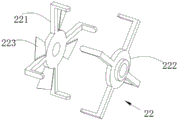
22. a driving mechanism; 221. a front end driving frame; 222. a rear end driving frame; 223. a fan blade;
3. a one-way valve; 4. a rubber tube; 5. a fan housing; 51. a housing; 52. a side air port; 53. and an inclined guide plate.
Description of the embodiments
The following description of the embodiments of the present invention will be made clearly and completely with reference to the accompanying drawings, in which it is apparent that the embodiments described are only some embodiments of the present invention, but not all embodiments. All other embodiments, which can be made by those skilled in the art based on the embodiments of the invention without making any inventive effort, are intended to be within the scope of the invention.
In the description of the present invention, it should be understood that the terms "center", "longitudinal", "lateral", "length", "width", "thickness", "upper", "lower", "front", "rear", "left", "right", "vertical", "horizontal", "top", "bottom", "inner", "outer", "clockwise", "counterclockwise", etc. indicate orientations or positional relationships based on the orientations or positional relationships shown in the drawings are merely for convenience in describing the present invention and simplifying the description, and do not indicate or imply that the apparatus or elements referred to must have a specific orientation, be configured and operated in a specific orientation, and thus should not be construed as limiting the present invention.
At present, when the motor is cooled, air cooling or water cooling is mostly adopted, when the air cooling is adopted, fan blades are directly installed on the motor, but the method of adopting the fan blades to dissipate heat can be adopted under the working state of the motor in a short time, when the motor is used for a long time, the temperature on the motor body rises, the air cooling effect of the motor body can be deteriorated, so that the cooling effect of the air cooling on the motor can be influenced, and when the water cooling is adopted, an external electric appliance needs to be connected, such as a water pump drives water to flow to absorb heat on the motor, the cooling effect of the effect is good, but extra electric appliances are used for cooling the motor, and the energy consumption of the motor in use can be enhanced, so that the motor which can effectively cool and can not increase the electric appliance is required.
Examples
In order to solve the above-mentioned problems, referring to fig. 1, one of the purposes of the present embodiment is to provide a motor cooling treatment device, which includes a housing 1 and a cooling mechanism 2 disposed on the housing 1, wherein the housing 1 limits the position of the cooling mechanism 2, so that the cooling mechanism 2 can be stably mounted on the housing 1, and meanwhile, in the process that the cooling mechanism 2 is limited, the housing 1 drives the cooling mechanism 2 to reciprocate, and in the process that the cooling mechanism 2 reciprocates, a water source is collected to the outside, so that the water source enters into the cooling mechanism 2, and the collected water source absorbs heat generated by the housing 1, so that the temperature on the housing 1 is reduced, and meanwhile, when the cooling mechanism 2 reciprocates to collect the water source into the cooling mechanism 2, the use of other electrical appliances is reduced, so that energy is saved, and meanwhile, air flow generated by the housing 1 is guided by the cooling mechanism 2, so that the air flow absorbs heat emitted by the cooling mechanism 2 and blows away from the cooling mechanism 2, so that heat is prevented from being collected in the vicinity of the cooling mechanism 2 and affecting the heat emitted by the cooling mechanism 2;
under the condition that no new electric appliance is added, the cooling mechanism 2 collects water sources to cool the shell 1, air flow generated by the shell 1 cools the cooling mechanism 2 in the water cooling and cooling process, and the cooling mechanism 2 guides the air flow in the air flow blowing process, so that the air flow carries a large amount of heat from the cooling mechanism 2, and heat dissipation on the cooling mechanism 2 is quickened, thereby ensuring effective cooling of the shell 1, and ensuring that the temperature on the shell 1 is not too high to influence the use of the shell 1 when the shell 1 is used for a long time.
In order to achieve the above-mentioned effects, please refer to fig. 1-8, the casing 1 includes a stator housing 11 for wrapping a rotor of the motor, a full-sliding collar 12 and a half-sliding collar 13 are respectively sleeved and fixed at two ends of the stator housing 11, the cooling mechanism 2 includes a water cooling device 21, and the full-sliding collar 12 and the half-sliding collar 13 limit positions of the water cooling device 21, so that the water cooling device 21 can be stably mounted on the casing 1, so that the water cooling device 21 can work subsequently.
The water cooling device 21 comprises a rear end slip ring 211 and a front end slip ring 212, the rear end slip ring 211 and the front end slip ring 212 are equal in size and are annular, meanwhile, the rear end slip ring 211 is slidably sleeved on the full slip collar 12, an extrusion opening communicated with the outside is formed in the inner side wall of the front end slip ring 212, one end of the half slip ring 13 is slidably inserted into the extrusion opening, the front end slip ring 212 is slidably sleeved on the stator shell 11, a sealed cavity is formed among the half slip ring 13, the stator shell 11 and the front end slip ring 212, when the shell 1 drives the cooling mechanism 2 to move, the rear end slip ring 211 and the front end slip ring 212 slide on the full slip collar 12 and the half slip ring 13 respectively, in order to improve the stability of the water cooling device, the rear end slip ring 211, the front end slip ring 212 and the half slip ring 13 cannot fall off from the full slip collar 12 and the half slip ring 13 when the rear end slip ring 211 and the front end slip ring 212 slide on the full slip collar 12, the end of the half slip ring 13 is also provided with a baffle ring, the rear end slip ring 211 and the front end slip ring 212 is blocked by the baffle ring 212.
Meanwhile, in order to enable the water cooling device 21 to collect external cooling water into the interior when in reciprocating movement, the cooling water absorbs heat emitted by the stator housing 11, the interiors of the rear end slip ring 211 and the front end slip ring 212 are hollow structures, cooling water for cooling is received by the interiors of the front end slip ring 212 and the rear end slip ring 211, the one-way valves 3 are connected to the rear end slip ring 211 and the front end slip ring 212, the one-way valves 3 connected with the rear end slip ring 211 are connected with the rubber tubes 4 communicated with an external water tank, the one-way valves 3 connected with the rear end slip ring 211 are used for blocking the cooling water from flowing out, and meanwhile, in order to enable the cooling water between the rear end slip ring 211 and the front end slip ring 212 to flow, a plurality of connecting tubes 213 are fixed on the side walls of the rear end slip ring 211 and the front end slip ring 212, the interiors of the rear end slip ring 211 and the front end slip ring 212 are communicated, and the cooling water can flow between the rear end slip ring 211 and the front end slip ring 212.
The driving mechanism 22 is arranged on the water cooling device 21, the driving mechanism 22 is used for driving the water cooling device 21 to reciprocate on the stator housing 11, the casing 1 drives the driving mechanism 22 to drive the water cooling device 21 to reciprocate on the casing 1, when the driving mechanism 22 drives the water cooling device 21 to reciprocate, and when the water cooling device 21 moves towards the direction close to the front end driving frame 221, one end of the half sliding sleeve ring 13 is inserted into the front end sliding ring 212, the space inside the front end sliding ring 212 is reduced, cooling water inside the front end sliding ring 212 is extruded, the cooling water flows outwards through the one-way valve 3, but the one-way valve 3 connected with the rear end sliding ring 211 blocks the outflow of the cooling water, so that part of the cooling water in the front end sliding ring 212 is discharged through the one-way valve 3, when the water cooling device 21 moves toward the rear end driving frame 222, a part of the half slip ring 13 moves away from the front end slip ring 212, and at this time, the space inside the front end slip ring 212 expands, the air pressure inside the front end slip ring 212 is reduced, the front end slip ring 212 absorbs the cooling water to the outside, the check valve 3 connected with the front end slip ring 212 blocks the cooling water from flowing into the front end slip ring 212, the front end slip ring 212 absorbs the cooling water inside the rear end slip ring 211, the cooling water in the rear end slip ring 211 is absorbed into the front end slip ring 212 through the connecting pipe 213, and at the same time, when the liquid in the rear end slip ring 211 flows to the front end slip ring 212, the rear end slip ring 211 absorbs the cooling water to the outside through the rubber tube 4, so that the cooling water inside the water cooling device 21 is replaced, the cooling water entering into the water cooling device 21 absorbs the heat generated by the stator housing 11, the water cooling device 21 can continuously cool down the stator housing 11 by water cooling.
Meanwhile, when the water cooling device 21 cools the stator housing 11, no other electric appliances are added, so that electric energy is saved.
In order to make the driving mechanism 22 drive the water cooling device 21 to reciprocate, the structure of the driving mechanism 22 is thinned, the driving mechanism 22 comprises a front end driving frame 221 and a rear end driving frame 222, a plurality of supporting rods extending outwards are arranged on the front end driving frame 221 and the rear end driving frame 222, the front end driving frame 221 and the rear end driving frame 222 are respectively arranged at two ends of the stator shell 11 and are connected with rotor bearings of the stator shell 11, the rotor bearings on the stator shell 11 drive the front end driving frame 221 and the rear end driving frame 222 to rotate, the rear end sliding ring 211 and the front end sliding ring 212 are fixed with the bonding pressing ring 214 at one side far away from each other, the bonding pressing ring 214 is an annular wavy line, the supporting rods on the rear end driving frame 222 are uniformly arranged in a protruding and recessed mode, when the supporting rods on the front end driving frame 221 are contacted with the outermost end of the bonding pressing ring 214, and when the front end driving frame 221 and the rear end driving frame 222 rotate, the supporting rods on the bonding pressing ring 214 are pushed by the supporting rods, so that the rear end sliding ring 211 and the front end sliding ring 212 slide on the stator shell 11 in a reciprocating manner.
In order to avoid the problem that the rear end slip ring 211 and the front end slip ring 212 are driven to rotate when the abutting rod pushes the abutting ring 214, the stator housing 11 is sleeved with the positioning ring 14, a plurality of limiting plates 16 are fixed on the positioning ring 14, the limiting plates 16 clamp the positions of the connecting pipes 213, the sliding direction of the connecting pipes 213 is limited, the stable horizontal sliding of the rear end slip ring 211 and the front end slip ring 212 is ensured, and meanwhile, the outwardly extending limiting plates 16 conduct and radiate heat on the stator housing 11, so that the heat diffusion on the stator housing 11 is accelerated.
In order to facilitate the fixing of the position of the stator housing 11, a positioning frame 15 for positioning the stator housing 11 is fixed to the bottom of the positioning ring 14, and the position of the stator housing 11 is fixed by positioning the positioning frame 15 with screws.
When the limiting plate 16 is provided on the stator housing 11, the installation of the connection pipe 213 is hindered, and in order to facilitate the installation of the rear end slip ring 211 and the front end slip ring 212 on the stator housing 11, one end of the connection pipe 213 is inserted into the front end slip ring 212, and the connection pipe 213 and the front end slip ring 212 are fixedly connected together by nuts, so that the water cooling device 21 is assembled by inserting the connection pipe 213 and the front end slip ring 212 when the installation of the rear end slip ring 211 and the front end slip ring 212 is performed.
In order to improve the heat dissipation effect of the device, the front end driving frame 221 is provided with the fan blades 223, when the fan blades 223 rotate, air flow blowing the water cooling device 21 is generated, heat dissipated on the water cooling device 21 is blown away through the air flow, meanwhile, when the water cooling device 21 moves back and forth, the dissipation of the heat can be accelerated, and the heat dissipation effect of the water cooling device 21 is improved.
In order to further improve the heat dissipation effect of the water cooling device 21, an air outlet slot 215 is formed in the side wall of the front end slip ring 212, one end of the air outlet slot 215 penetrates through the side wall of the front end slip ring 212 close to the rear end slip ring 211, a plurality of connecting ports are formed in the air outlet slot 215 and the outer wall of the front end slip ring 212, air flow generated by the fan blades 223 enters the air outlet slot 215 through the connecting ports and blows towards the rear end slip ring 211, meanwhile, an upward inclined air passing slot 216 is formed in the position, corresponding to the air outlet slot 215, of the rear end slip ring 211, one end of the air passing slot 216 penetrates out of the outer side wall of the rear end slip ring 211, air flow blown from the air passing slot 215 passes through the air passing slot 216 and is far away from the water cooling device 21, so that the air flow drives away part of air flow inside the rear end slip ring 211 and the front end slip ring 212, heat dissipation of the water cooling device 21 is accelerated, and meanwhile, the air flow flowing out of the air flow from the air outlet slot 215 blows away heat dissipation from the limiting plate 16, and heat is prevented from gathering near the stator housing 11.
Examples
Considering that the air flow generated when the fan blades 223 rotate is directly blown to the water cooling device 21, there is a problem that heat emitted by the water cooling device 21 is accumulated near the water cooling device 21, so that the heat in the air near the water cooling device 21 wraps up the water cooling device 21, and the heat emitted by the water cooling device 21 is slowly diffused, in order to solve the problem, referring to fig. 9-10, a fan housing 5 is arranged at one end of the stator housing 11 near the front end slip ring 212, the fan housing 5 is sleeved inside, the fan housing 5 comprises a housing 51, the housing 51 is fixedly connected with a limiting plate 16, the fan blades 223 are arranged inside the housing 51, a gap exists between the housing 51 and the front end slip ring 212, the air flow generated by the fan blades 223 can directly blow the front end slip ring 212, a plurality of side air ports 52 are formed on the side wall of the housing 51, and inclined guide plates 53 inclined towards the inside of the side air ports 52 are arranged, and part of the air flow generated by the fan blades 223 moves towards the outside of the water cooling device 21 through the guide plates 53, so that the air flow leaving from the fan housing 5 is in an umbrella shape and is outwardly diffused, the air flow leaving the fan housing 5 is fixedly connected with the housing 51, a gap exists between the housing 51 and a gap exists between the front end slip ring 212, so that the air flow generated by the fan blade 223 is directly adjacent to the front end of the water cooling device 21 is directly blown to the air, and the heat is quickly diffused by the air cooling device 21, and the heat is quickly diffused by the air cooling device, and the heat is avoided.
The second object of the present invention is to provide a method for cooling by operating a motor cooling treatment device comprising any one of claims 1 to 9, comprising the steps of:
s1, conveying cooling water into the rear end slip ring 211 through a rubber pipe 4, enabling the cooling water to enter the rear end slip ring 211 through a one-way valve 3, and enabling the front end slip ring 212 to be filled with the cooling water through guidance of a connecting pipe 213;
s2, when the rotor in the stator shell 11 rotates, the rotor drives the front end driving frame 221 and the rear end driving frame 222 to rotate, when the front end driving frame 221 and the rear end driving frame 222 rotate, the water cooling device 21 moves reciprocally on the stator shell 11 through friction between the abutting rod and the abutting pressing ring 214, during the reciprocal movement of the water cooling device 21, when the water cooling device 21 moves towards the direction close to the front end driving frame 221, one end of the half sliding sleeve ring 13 is inserted into the front end sliding ring 212, at the moment, the space inside the front end sliding ring 212 is reduced, part of cooling water in the front end sliding ring 212 is discharged through the one-way valve 3, and when the water cooling device 21 moves towards the direction close to the rear end driving frame 222, part of the half sliding sleeve ring 13 leaves the front end sliding ring 212, at the moment, the space inside the front end sliding ring 212 is enlarged, cooling water inside the rear end sliding ring 211 is absorbed by the front end sliding ring 212, and then the outside cooling water absorbed by the rubber tube 4 enters the rear end sliding ring 211, and the cooling water entering the water cooling device 21 absorbs heat generated by the stator shell 11;
s3, air flow generated by rotation of the fan blades 223 blows towards the water cooling device 21, so that heat emitted from the water cooling device 21 is blown away, meanwhile, part of air flow enters the air outlet groove 215, part of heat in the front end slip ring 212 is taken away, part of air flow from the air outlet groove 215 enters the air passing groove 216, and part of heat on the rear end slip ring 211 is taken away.
The foregoing has shown and described the basic principles, principal features and advantages of the invention. It will be understood by those skilled in the art that the present invention is not limited to the above-described embodiments, and that the above-described embodiments and descriptions are only preferred embodiments of the present invention, and are not intended to limit the invention, and that various changes and modifications may be made therein without departing from the spirit and scope of the invention as claimed. The scope of the invention is defined by the appended claims and equivalents thereof.
Claims (10)
1. The utility model provides a motor cooling processing apparatus, includes casing (1) and sets up cooling mechanism (2) on casing (1), casing (1) restrict cooling mechanism (2) position, its characterized in that: in the process that cooling mechanism (2) is restricted, casing (1) is with cooling mechanism (2) drive reciprocating motion, and in the in-process of cooling mechanism (2) reciprocating motion, outwards gather the water source, and absorb the heat that casing (1) produced through the water source of gathering, the air current that casing (1) produced at the during operation simultaneously is guided by cooling mechanism (2), makes the air current absorb the heat that cooling mechanism (2) distributes, and blows away from cooling mechanism (2) with the heat that cooling mechanism (2) distributes.
2. The motor cooling treatment device according to claim 1, wherein: the machine shell (1) comprises a stator shell (11) wrapping a motor rotor, a full sliding sleeve ring (12) and a half sliding sleeve ring (13) are sleeved and fixed at two ends of the stator shell (11) respectively, the cooling mechanism (2) comprises a water cooling device (21), and the full sliding sleeve ring (12) and the half sliding sleeve ring (13) limit the position of the water cooling device (21).
3. The motor cooling treatment device according to claim 2, wherein: the water cooling device (21) comprises a rear end slip ring (211) and a front end slip ring (212), wherein the rear end slip ring (211) is slidably sleeved on the full-slip sleeve ring (12), an extrusion opening communicated with the outside is formed in the inner side wall of the front end slip ring (212), one end of the half-slip sleeve ring (13) is slidably inserted into the extrusion opening, and the front end slip ring (212) is slidably sleeved on the stator shell (11).
4. A motor cooling treatment device according to claim 3, wherein: the inside of rear end sliding ring (211) and front end sliding ring (212) is hollow structure, just be fixed with a plurality of connecting pipe (213) on the lateral wall that rear end sliding ring (211) is close to front end sliding ring (212), in front end sliding ring (212) were inserted to one end of connecting pipe (213) to link together connecting pipe (213) and front end sliding ring (212) fixed connection through the nut.
5. A motor cooling treatment device according to claim 3, wherein: a sealed cavity is formed among the semi-slip sleeve ring (13), the stator housing (11) and the front end slip ring (212), cooling water for cooling is received in the front end slip ring (212) and the rear end slip ring (211), meanwhile, the rear end slip ring (211) and the front end slip ring (212) are connected with one-way valves (3), rubber pipes (4) communicated with an external water tank are connected to the one-way valves (3), the one-way valves (3) connected with the rear end slip ring (211) block the outflow of the cooling water, and the one-way valves (3) connected with the front end slip ring (212) block the inflow of the cooling water.
6. A motor cooling treatment device according to claim 3, wherein: install actuating mechanism (22) on water cooling plant (21), actuating mechanism (22) are used for driving water cooling plant (21) reciprocating motion on stator housing (11), actuating mechanism (22) are including front end drive frame (221) and rear end drive frame (222), all be equipped with the outside butt pole that extends of a plurality of on front end drive frame (221), rear end drive frame (222), front end drive frame (221) and rear end drive frame (222) set up respectively at the both ends of stator housing (11), and are connected with the rotor bearing of stator housing (11), one side that rear end sliding ring (211) and front end sliding ring (212) keep away from each other is fixed with laminating clamping ring (214), laminating clamping ring (214) are annular wavy line, and when the outer end contact of butt pole on front end drive frame (221) and laminating clamping ring (214), the butt pole on rear end drive frame (222) and laminating clamping ring (214) are innermost contact.
7. The motor cooling treatment device according to claim 6, wherein: the front end driving frame (221) is provided with fan blades (223), when the fan blades (223) rotate, air flow blowing to the water cooling device (21) is generated, an air outlet groove (215) is formed in the side wall of the front end sliding ring (212), one end of the air outlet groove (215) penetrates through the side wall, close to the rear end sliding ring (211), of the front end sliding ring (212), the air flow generated by the fan blades (223) enters the air outlet groove (215) and blows towards the rear end sliding ring (211) through the air outlet groove (215), an upward inclined air passing groove (216) is formed in the position, corresponding to the air outlet groove (215), of the rear end sliding ring (211), and the air flow blowing from the air outlet groove (215) passes through the air passing groove (216) and is far away from the water cooling device (21).
8. The motor cooling treatment device according to claim 4, wherein: the stator housing (11) is sleeved with a positioning ring (14), a positioning frame (15) for positioning the stator housing (11) is fixed at the bottom of the positioning ring (14), a plurality of limiting plates (16) are fixed on the positioning ring (14), the limiting plates (16) clamp the positions of the connecting pipes (213) and limit the sliding direction of the connecting pipes (213).
9. The motor cooling treatment device according to claim 7, wherein: the stator housing (11) is close to one end of front end sliding ring (212) and is provided with fan housing (5), fan housing (5) cover is established in inside with flabellum (223), fan housing (5) are including housing (51), flabellum (223) set up in the inside of housing (51), a plurality of side air port (52) have been seted up on the lateral wall of housing (51) to be provided with inclined guide board (53) towards the inside slope of housing (51) in one side of side air port (52), the outside removal of water cooling plant (21) is passed through to the guide of inclined guide board (53) partial air current that fan blade (223) produced.
10. A method of cooling by operation of a cooling treatment apparatus comprising a motor as claimed in any one of claims 1 to 9, characterized in that: the method comprises the following steps:
s1, conveying cooling water into the rear end slip ring (211) through a rubber pipe (4), enabling the cooling water to enter the rear end slip ring (211) through a one-way valve (3), and enabling the front end slip ring (212) to be filled with the cooling water through guidance of a connecting pipe (213);
s2, when a rotor in a stator shell (11) rotates, the rotor drives a front end driving frame (221) and a rear end driving frame (222) to rotate, when the front end driving frame (221) and the rear end driving frame (222) rotate, a water cooling device (21) moves reciprocally on the stator shell (11) through friction of a supporting rod and a bonding pressing ring (214), in the process of the reciprocal movement of the water cooling device (21), one end of a half sliding sleeve ring (13) is inserted into the front end sliding ring (212) when the water cooling device (21) moves towards the direction close to the front end driving frame (221), at the moment, the space inside the front end sliding ring (212) is reduced, part of cooling water in the front end sliding ring (212) is discharged through a one-way valve (3), and when the water cooling device (21) moves towards the direction close to the rear end driving frame (222), a part of the half sliding sleeve ring (13) leaves the front end sliding ring (212), at the moment, the space inside the front end sliding ring (212) is enlarged, the front end sliding ring (211) absorbs cooling water inside the rear end sliding ring (211) to absorb heat, and then the cooling water inside the stator shell (211) absorbs heat to the cooling water, and the cooling water enters the outer shell (11) to absorb heat;
s3, air flow generated by rotation of the fan blades (223) blows towards the water cooling device (21), so that heat emitted from the water cooling device (21) is blown away, part of the air flow enters the air outlet groove (215), part of the heat in the front end slip ring (212) is taken away, part of the air flow from the air outlet groove (215) enters the air passing groove (216), and part of the heat on the rear end slip ring (211) is taken away.
Priority Applications (1)
| Application Number | Priority Date | Filing Date | Title |
|---|---|---|---|
| CN202310145493.7A CN116155032A (en) | 2023-02-21 | 2023-02-21 | Motor cooling treatment device and cooling method |
Applications Claiming Priority (1)
| Application Number | Priority Date | Filing Date | Title |
|---|---|---|---|
| CN202310145493.7A CN116155032A (en) | 2023-02-21 | 2023-02-21 | Motor cooling treatment device and cooling method |
Publications (1)
| Publication Number | Publication Date |
|---|---|
| CN116155032A true CN116155032A (en) | 2023-05-23 |
Family
ID=86361572
Family Applications (1)
| Application Number | Title | Priority Date | Filing Date |
|---|---|---|---|
| CN202310145493.7A Pending CN116155032A (en) | 2023-02-21 | 2023-02-21 | Motor cooling treatment device and cooling method |
Country Status (1)
| Country | Link |
|---|---|
| CN (1) | CN116155032A (en) |
-
2023
- 2023-02-21 CN CN202310145493.7A patent/CN116155032A/en active Pending
Similar Documents
| Publication | Publication Date | Title |
|---|---|---|
| CN109274220B (en) | High-efficient heat dissipation motor | |
| KR101817616B1 (en) | Compressor assembly | |
| US10859098B2 (en) | Drive device | |
| KR101817612B1 (en) | Air injector equipment set for cooling a motor | |
| CN213990430U (en) | Liquid cooling type energy-saving permanent magnet synchronous motor | |
| CN214464524U (en) | Diesel engine cooling water pump and diesel engine cooling water circulation system | |
| CN115208116B (en) | Plastic package direct current brushless motor for clothes dryer | |
| KR20160110213A (en) | Compressor assembly structure with heat dissipation member for motor | |
| CN218006020U (en) | Motor bearing is with mobile type water-cooling circulation heat abstractor | |
| CN216414051U (en) | Motor housing with combined type cooling structure | |
| CN213152689U (en) | Heat dissipation type electric power automation equipment based on semiconductor refrigeration | |
| CN111969768B (en) | Three-phase motor with heat abstractor | |
| CN211930438U (en) | Desulfurization motor circulative cooling device | |
| CN116155032A (en) | Motor cooling treatment device and cooling method | |
| CN219351680U (en) | Solar photovoltaic panel with good heat dissipation performance | |
| CN213426789U (en) | Power management device with good heat dissipation performance | |
| CN113872392A (en) | Stable direct-drive motor with double cooling mechanisms | |
| CN219509888U (en) | Automobile electronic water pump with cooling function | |
| CN218155599U (en) | New energy automobile water-cooled condenser | |
| CN220582571U (en) | Heat radiator for central air conditioner outdoor unit | |
| CN220275524U (en) | Dust collector with heat dissipation function | |
| CN219268664U (en) | Direct-drive motor with heat dissipation mechanism | |
| CN216530801U (en) | Motor base with air-cooling and water-cooling combined type heat dissipation structure | |
| CN218071182U (en) | Oil cooling device of large ceiling fan motor | |
| CN210468988U (en) | Integrated driving motor |
Legal Events
| Date | Code | Title | Description |
|---|---|---|---|
| PB01 | Publication | ||
| PB01 | Publication | ||
| SE01 | Entry into force of request for substantive examination | ||
| SE01 | Entry into force of request for substantive examination |