CN116145636A - Multi-terrain foundation tamping device for civil engineering - Google Patents
Multi-terrain foundation tamping device for civil engineering Download PDFInfo
- Publication number
- CN116145636A CN116145636A CN202211383228.4A CN202211383228A CN116145636A CN 116145636 A CN116145636 A CN 116145636A CN 202211383228 A CN202211383228 A CN 202211383228A CN 116145636 A CN116145636 A CN 116145636A
- Authority
- CN
- China
- Prior art keywords
- hydraulic cylinder
- guide frame
- arm
- terrain
- civil engineering
- Prior art date
- Legal status (The legal status is an assumption and is not a legal conclusion. Google has not performed a legal analysis and makes no representation as to the accuracy of the status listed.)
- Withdrawn
Links
Images


Classifications
-
- E—FIXED CONSTRUCTIONS
- E02—HYDRAULIC ENGINEERING; FOUNDATIONS; SOIL SHIFTING
- E02D—FOUNDATIONS; EXCAVATIONS; EMBANKMENTS; UNDERGROUND OR UNDERWATER STRUCTURES
- E02D3/00—Improving or preserving soil or rock, e.g. preserving permafrost soil
- E02D3/02—Improving by compacting
- E02D3/046—Improving by compacting by tamping or vibrating, e.g. with auxiliary watering of the soil
- E02D3/068—Vibrating apparatus operating with systems involving reciprocating masses
-
- F—MECHANICAL ENGINEERING; LIGHTING; HEATING; WEAPONS; BLASTING
- F16—ENGINEERING ELEMENTS AND UNITS; GENERAL MEASURES FOR PRODUCING AND MAINTAINING EFFECTIVE FUNCTIONING OF MACHINES OR INSTALLATIONS; THERMAL INSULATION IN GENERAL
- F16F—SPRINGS; SHOCK-ABSORBERS; MEANS FOR DAMPING VIBRATION
- F16F15/00—Suppression of vibrations in systems; Means or arrangements for avoiding or reducing out-of-balance forces, e.g. due to motion
- F16F15/02—Suppression of vibrations of non-rotating, e.g. reciprocating systems; Suppression of vibrations of rotating systems by use of members not moving with the rotating systems
- F16F15/04—Suppression of vibrations of non-rotating, e.g. reciprocating systems; Suppression of vibrations of rotating systems by use of members not moving with the rotating systems using elastic means
- F16F15/06—Suppression of vibrations of non-rotating, e.g. reciprocating systems; Suppression of vibrations of rotating systems by use of members not moving with the rotating systems using elastic means with metal springs
- F16F15/067—Suppression of vibrations of non-rotating, e.g. reciprocating systems; Suppression of vibrations of rotating systems by use of members not moving with the rotating systems using elastic means with metal springs using only wound springs
Landscapes
- Engineering & Computer Science (AREA)
- General Engineering & Computer Science (AREA)
- Structural Engineering (AREA)
- Life Sciences & Earth Sciences (AREA)
- Paleontology (AREA)
- Soil Sciences (AREA)
- General Life Sciences & Earth Sciences (AREA)
- Mining & Mineral Resources (AREA)
- Environmental & Geological Engineering (AREA)
- Civil Engineering (AREA)
- Agronomy & Crop Science (AREA)
- Physics & Mathematics (AREA)
- Acoustics & Sound (AREA)
- Aviation & Aerospace Engineering (AREA)
- Mechanical Engineering (AREA)
- Investigation Of Foundation Soil And Reinforcement Of Foundation Soil By Compacting Or Drainage (AREA)
Abstract
The invention relates to the technical field of foundation tamping equipment, in particular to a multi-terrain foundation tamping device for civil engineering, which comprises a tamping machine body, a guide frame and a transverse movement driving mechanism; the guide frame comprises two track frames which are arranged at two sides of the tamper body; the two transverse moving driving mechanisms are respectively arranged on the two track frames, one end of each transverse moving driving mechanism is connected with the track frame, the other end of each transverse moving driving mechanism is fixedly connected with the tamper body, and each transverse moving driving mechanism is used for driving the tamper body to do reciprocating linear motion on the guide frame. The guide frame and the sideslip actuating mechanism, the reciprocating rectilinear motion is done on the guide frame to the sideslip actuating mechanism drive rammer body, and the rammer body is automatic to the ground of guide frame within range tamps, and the rammer body has realized the ground of automatic tamp guide frame within range at the in-process of tamping ground, reduces artifical the participation, has reduced constructor's intensity of labour.
Description
Technical Field
The invention relates to the technical field of foundation tamping equipment, in particular to a multi-terrain foundation tamping device for civil engineering.
Background
With the continuous progress of science and technology and the development of engineering practice, people always keep attention on engineering quality, safety progress and cost in the construction process of civil engineering, and foundation construction is the first step of engineering. In the foundation construction process, the foundation needs to be rammed. Earth and stone mixtures are generally applied to engineering construction of roadbeds, dykes and the like in China, and the earth and stone mixtures need to be tamped.
The current general method for ramming soil is to divide the ramming of soil layers into high-intensity manual labor with a lot of labor force, and in the modern foundation ramming process, a foundation ramming device is generally adopted to ramm the foundation to replace manual ramming operation of workers.
Currently, the existing foundation tamping devices on the market are mostly compacting machines for tamping backfill soil and stone mixtures by utilizing the impact and impact vibration actions, and are generally handheld tamping devices. In the use, need constructor unanimous hand to hold ramming device work, constructor intensity of labour is big, especially under high temperature environment, constructor hardly keeps long-time work.
Disclosure of Invention
To the problem that prior art exists, provide a multi-terrain foundation ramming device for civil engineering, this application is through setting up rammer body, guide frame and sideslip actuating mechanism, and constructor removes the guide to the ground that needs to tamp, and sideslip actuating mechanism drives the rammer body and makes reciprocating rectilinear motion on the guide frame, realizes the automatic tamping ground of rammer body, has reduced constructor's intensity of labour. .
In order to solve the problems in the prior art, the invention adopts the following technical scheme:
a multi-terrain foundation tamping device for civil engineering comprises a tamping machine body, a guide frame and a transverse movement driving mechanism;
the guide frame comprises two track frames which are arranged at two sides of the tamper body;
the two transverse moving driving mechanisms are respectively arranged on the two track frames, one end of each transverse moving driving mechanism is connected with the track frame, the other end of each transverse moving driving mechanism is fixedly connected with the tamper body, and each transverse moving driving mechanism is used for driving the tamper body to do reciprocating linear motion on the guide frame.
Preferably, the transverse moving driving mechanism comprises a linear motor, a connecting frame, a moving trolley, a connecting block, a connecting rod and a first connecting arm, and a second sliding groove is formed in the rail frame;
the linear motor is arranged below the track frame and is fixedly connected with the track frame through the connecting frame;
the movable trolley is arranged in the second chute;
the upper end of the connecting block penetrates through the track frame to be fixedly connected with the lower end of the movable trolley, and the lower end of the connecting block is fixedly connected with the linear motor;
the four connecting rods are vertically arranged, and the lower ends of the four connecting rods are arrayed in the middle of the movable trolley and fixedly connected with the movable trolley;
one end of the first connecting arm is fixedly connected with the tamper body, the upper ends of the four connecting rods penetrate through one end of the first connecting arm, and the connecting rods are in sliding connection with the first connecting arm.
Preferably, the lateral movement driving mechanism further comprises a second damping structure, and the second damping structure comprises a first hydraulic cylinder and a second damping spring;
the upper end of the first hydraulic cylinder is hinged with the first connecting arm, and the lower end of the first hydraulic cylinder is hinged with the middle part of the mobile trolley;
the second damping spring is sleeved on the second hydraulic cylinder, the upper end of the second damping spring is fixedly connected with the upper end of the second hydraulic cylinder, and the lower end of the second damping spring is fixedly connected with the lower end of the first hydraulic cylinder.
Preferably, the guide frame further comprises a hydraulic leg;
the hydraulic support legs are four, and the four hydraulic support legs are respectively arranged at four corners of the guide frame.
Preferably, the lower end of the hydraulic support leg is provided with a positioning hole.
Preferably, the front end and the rear end of the guide frame are both provided with movable handles.
Preferably, the multi-terrain foundation compacting device for civil engineering further comprises an auxiliary supporting structure;
the two auxiliary support structures are arranged on two sides of the tamper body and are matched with the two transverse moving driving mechanisms, and the auxiliary support structures comprise a first support arm and a second support arm;
the first supporting arm is arranged on one side of the transverse moving driving mechanism, one end of the first supporting arm is connected with the track frame, and the other end of the first supporting arm is connected with the tamper body;
the second support arm is arranged on the other side of the transverse moving driving mechanism, one end of the second support arm is connected with the track frame, and the other end of the second support arm is connected with the tamper body.
Preferably, the first support arm comprises a second sliding block, a second hydraulic cylinder, a third damping spring, a second connecting arm and a second sliding block, and the second support arm comprises a third hydraulic cylinder, a fourth damping spring, a third connecting arm and a third sliding block;
one end of the second connecting arm is fixedly connected with the tamper body;
the second sliding block is arranged in the second sliding groove;
one end of the second hydraulic cylinder is hinged with the other end of the second connecting arm, and the other end of the second hydraulic cylinder is hinged with the upper end of the second sliding block;
the third damping spring is sleeved on the second hydraulic cylinder, and two ends of the third damping spring are respectively connected with two ends of the second hydraulic cylinder;
one end of the third connecting arm is fixedly connected with the tamper body;
the third sliding block is arranged in the second sliding groove;
one end of the third hydraulic cylinder is hinged with the other end of the third connecting arm, and the other end of the third hydraulic cylinder is hinged with the upper end of the third sliding block;
the fourth damping spring is sleeved on the third hydraulic cylinder, and two ends of the fourth damping spring are respectively connected with two ends of the third hydraulic cylinder.
Preferably, the tamper body comprises a fixed column, a first sliding block, a first motor, a belt, a driven wheel and a first sliding groove;
the fixed column is vertically arranged and penetrates through the tamper body;
the two first sliding blocks are symmetrically arranged on the surface of the upper part of the fixed column;
the first motor is arranged outside the tamper body;
the driven wheel is arranged on the fixed column, and a first sliding groove on the driven wheel is matched with the first sliding block;
one end of the belt is in transmission connection with the output end of the first motor, and the other end of the belt is in transmission connection with the driven wheel.
Preferably, the tamper body further comprises a first shock absorbing structure, the first shock absorbing structure is arranged outside the tamper body, and the first shock absorbing structure comprises an upper connecting plate, a first shock absorbing spring and a lower connecting plate;
the upper connecting plate is sleeved on the fixed column and connected with the upper end of the fixed column;
the lower connecting plate is sleeved on the fixed column and is connected with the upper end of the tamper body;
the first damping spring is sleeved on the fixed column, the upper end of the first damping spring is connected with the upper connecting plate, and the lower end of the first damping spring is connected with the lower connecting plate.
Compared with the prior art, the beneficial effects of this application are:
the guide frame and the sideslip actuating mechanism, two sideslip actuating mechanism simultaneous working, drive the tamper body and do reciprocal rectilinear motion on the guide frame, the tamper body is automatic to tamp the ground of guide frame within range, after the ground of guide frame within range is tamped, the staff removes the guide frame again to the ground that next department needs to tamp, the tamper body is automatic to tamp the ground of guide frame within range again, the tamper body has realized the ground of automatic tamp guide frame within range at the in-process of tamping ground, manual participation is reduced, constructor's intensity of labour has been reduced.
The linear motor, the link, the travelling car, the connecting block, connecting rod and first linking arm, linear motor reciprocating rectilinear motion drives the travelling car through the connecting block and reciprocates rectilinear motion, and the removal of travelling car drives the connecting rod and removes to drive first linking arm and remove, and then realize driving the tamper main part and do reciprocating rectilinear motion on the guide frame.
Second shock-absorbing structure, rammer compactor body can produce vibrations at the during operation, and vibrations can be transmitted to travelling car along first linking arm to lead to the guide frame vibrations, through installing second shock-absorbing structure between first linking arm and travelling car, shock-absorbing structure can absorb some vibrations, and then makes the vibrations of guide frame reduce.
Drawings
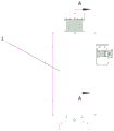
FIG. 1 is a front view of a multi-terrain foundation ramming apparatus for civil engineering of the present application;
FIG. 2 is a left side view of a multi-terrain foundation ramming apparatus for civil engineering of the present application;
FIG. 3 is a top view of a multi-terrain foundation ramming apparatus for civil engineering of the present application;
FIG. 4 is a perspective view of a multi-terrain foundation ramming apparatus for civil engineering of the present application;
FIG. 5 is a perspective view of the tamper body of the present application;
FIG. 6 is a front view of the tamper body of the present application;
FIG. 7 is a cross-sectional view at A-A of FIG. 6;
FIG. 8 is a perspective view of the driven shaft and stationary post of the present application;
FIG. 9 is a perspective view of a guide frame of the present application;
FIG. 10 is a partial view at B of FIG. 9;
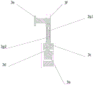
FIG. 11 is a perspective view of the traversing drive mechanism and track frame of the present application;
FIG. 12 is a front view of the traversing drive mechanism and track frame of the present application;
FIG. 13 is a cross-sectional view taken at C-C of FIG. 12;
FIG. 14 is a front view of the auxiliary support structure of the present application;
FIG. 15 is a sectional view taken at D-D of FIG. 14;
FIG. 16 is a perspective view of a first support arm of the present application;
fig. 17 is a perspective view of a second support arm of the present application.
The reference numerals in the figures are:
1-a tamper body; 1 a-fixing columns; 1a 1-a first slider; 1 b-a first motor; 1 c-driven wheel; 1c 1-a first chute; 1 d-belt; 1 e-a first shock absorbing structure; 1e 1-an upper connecting plate; 1e 2-lower connection plate; 1e 3-a first shock absorbing spring;
2-a guide frame; 2 a-track frame; 2a 1-a second chute; 2 b-hydraulic legs; 2b 1-positioning holes; 2 c-moving the handle;
3-a lateral movement driving mechanism; 3 A-A linear motor; 3 b-a connection frame 3 c-a travelling trolley; 3 d-connecting blocks; 3 e-a first connecting arm; 3 f-a connecting rod; 3 g-a second damping structure 3g 1-a first hydraulic cylinder; 3g 2-second damper spring;
4-an auxiliary support structure; 4 A-A first support arm; 4a 1-a second connecting arm; 4a 2-a second slider; 4a 3-a second hydraulic cylinder; 4a 4-a third damper spring; 4 b-a second support arm; 4b 1-a third connecting arm; 4b 2-a third slider; 4b 3-a third hydraulic cylinder; 4b 4-fourth damper springs.
Detailed Description
The invention will be further described in detail with reference to the drawings and the detailed description below, in order to further understand the features and technical means of the invention and the specific objects and functions achieved.
Referring to fig. 1 to 17, a multi-terrain foundation ramming apparatus for civil engineering is characterized by comprising a rammer body 1, a guide frame 2 and a traversing driving mechanism 3;
the guide frame 2 comprises two rail frames 2a, and the two rail frames 2a are arranged at two sides of the tamper body 1;
the two transverse moving driving mechanisms 3 are arranged, the two transverse moving driving mechanisms 3 are respectively arranged on the two track frames 2a, one end of each transverse moving driving mechanism 3 is connected with the track frame 2a, the other end of each transverse moving driving mechanism 3 is fixedly connected with the tamper body 1, and the transverse moving driving mechanisms 3 are used for driving the tamper body 1 to do reciprocating linear motion on the guide frame 2.
Through setting up guide frame 2 and sideslip actuating mechanism 3, the external power supply of whole equipment, during the staff is under construction, remove guide frame 2 to need the ground of tamping, tamper body 1 begins to tamp ground, two sideslip actuating mechanism 3 simultaneous working, drive tamper body 1 is reciprocating rectilinear motion on guide frame 2, tamper body 1 carries out automatic tamping to the ground of guide frame 2 within range, after the ground of guide frame 2 within range is tamped, the staff again removes guide frame 2 to the ground that next department needs to tamp, tamper body 1 is again automatic tamp the ground of guide frame 2 within range, tamper body 1 has realized the ground of automatic tamp guide frame 2 within range at the in-process of tamping ground, manual participation is reduced, constructor's intensity of labour has been reduced.
Referring to fig. 11 to 13, the traversing driving mechanism 3 includes a linear motor 3a, a connecting frame 3b, a moving trolley 3c, a connecting block 3d, a connecting rod 3f and a first connecting arm 3e, and the track frame 2a is provided with a second chute 2a1;
the linear motor 3a is arranged below the track frame 2a, and the linear motor 3a is fixedly connected with the track frame 2a through the connecting frame 3 b;
the moving trolley 3c is arranged in the second chute 2a1;
the upper end of the connecting block 3d passes through the track frame 2a and is fixedly connected with the lower end of the movable trolley 3c, and the lower end of the connecting block 3d is fixedly connected with the linear motor 3 a;
the four connecting rods 3f are arranged vertically, and the lower ends of the four connecting rods 3f are arrayed in the middle of the movable trolley 3c and fixedly connected with the movable trolley 3 c;
one end of the first connecting arm 3e is fixedly connected with the tamper body 1, the upper ends of the four connecting rods 3f penetrate through one end of the first connecting arm 3e, and the connecting rods 3f are in sliding connection with the first connecting arm 3 e.
Through setting up linear motor 3a, link 3b, travelling car 3c, connecting block 3d, connecting rod 3f and first linking arm 3e, linear motor 3a reciprocating rectilinear motion drives travelling car 3c through connecting block 3d and reciprocates rectilinear motion, and travelling car 3 c's removal drives connecting rod 3f and removes to drive first linking arm 3e and remove, and then realize driving the tamper main part and do reciprocating rectilinear motion on guide frame 2.
Referring to fig. 11 and 13, the traverse driving mechanism 3 further includes a second shock absorbing structure 3g, the second shock absorbing structure 3g including a first hydraulic cylinder 3g1 and a second shock absorbing spring 3g2;
the upper end of the first hydraulic cylinder 3g1 is hinged with the first connecting arm 3e, and the lower end of the first hydraulic cylinder 3g1 is hinged with the middle part of the movable trolley 3 c;
the second damping spring 3g2 is sleeved on the second hydraulic cylinder 4a3, the upper end of the second damping spring 3g2 is fixedly connected with the upper end of the second hydraulic cylinder 4a3, and the lower end of the second damping spring 3g2 is fixedly connected with the lower end of the first hydraulic cylinder 3g 1.
Through setting up second shock-absorbing structure 3g, rammer body 1 at the during operation, self can produce vibrations, and vibrations can be transmitted to travelling car 3c along first linking arm 3e to lead to guide frame 2 vibrations, through installing second shock-absorbing structure 3g between first linking arm 3e and travelling car 3c, shock-absorbing structure can absorb partial vibrations, and then makes the vibrations of guide frame 2 reduce.
Referring to fig. 9, the guide frame 2 further includes hydraulic legs 2b;
the hydraulic legs 2b have four, and the four hydraulic legs 2b are provided at the four corners of the guide frame 2, respectively.
Through setting up hydraulic support leg 2b, when horizontal ground construction, the tamper body 1 is in the tamping completion behind the ground of the guide frame 2 within range, constructor removes guide frame 2 to the ground for the tamp, two hydraulic support legs of one end of guide frame 2 are in the subaerial that does not tamp this moment, this place ground is higher, two hydraulic support legs of the other end of guide frame 2 are in the subaerial that has tamped this place ground is lower, guide frame 2 is in the inclination this moment, influence the operating condition of tamper body 1, can realize through hydraulic support leg 2b that guide frame 2 is in the horizontality, guarantee the operating condition of tamper body 1.
Referring to fig. 10, the lower end of the hydraulic leg 2b is provided with a positioning hole 2b1.
Through setting up locating hole 2b1, when the construction, constructor removes guide frame 2 to the ground department that needs tamp, inserts the locating pin in locating hole 2b1, and the fixed column 1a guides the position of frame 2, has prevented that the vibrations that tamper body 1 produced in the course of the work from driving guide frame 2 and moving.
As shown in fig. 9, both front and rear ends of the guide frame 2 are provided with moving handles 2c.
Through setting up removal handle 2c, constructor can hold removal handle 2c and remove guide frame 2 when removing guide frame 2, has made things convenient for constructor construction.
Referring to fig. 14 to 15, the multi-terrain foundation compacting device for civil engineering further includes an auxiliary support structure 4;
the auxiliary supporting structures 4 are two, the two auxiliary supporting structures 4 are arranged on two sides of the tamper body 1 and are matched with the two transverse moving driving mechanisms 3, and the auxiliary supporting structures 4 comprise a first supporting arm 4a and a second supporting arm 4b;
the first supporting arm 4a is arranged on one side of the transverse moving driving mechanism 3, one end of the first supporting arm 4a is connected with the track frame 2a, and the other end of the first supporting arm 4a is connected with the tamper body 1;
the second supporting arm 4b is disposed on the other side of the traversing driving mechanism 3, one end of the second supporting arm 4b is connected with the track frame 2a, and the other end of the second supporting arm 4b is connected with the tamper body 1.
Through setting up first support arm 4a and second support arm 4b, when ramming the slope surface, constructor removes guide frame 2 to on the slope surface, and when rammer body 1 rammed the slope surface, the work end needs perpendicular slope surface, and first support arm 4a and second support arm 4b mutually support, can keep sideslip actuating mechanism 3 to compress tightly on guide frame 2, can keep the work end perpendicular to ground of rammer body 1 again, has realized that rammer body 1 can work and tamp the slope surface at the slope surface.
Referring to fig. 16 and 17, the first support arm 4a includes a second slider 4a2, a second hydraulic cylinder 4a3, a third damper spring 4a4, a second link arm 4a1, and a second slider 4a2, and the second support arm 4b includes a third hydraulic cylinder 4b3, a fourth damper spring 4b4, a third link arm 4b1, and a third slider 4b2;
one end of the second connecting arm 4a1 is fixedly connected with the tamper body 1;
the second sliding block 4a2 is arranged in the second sliding groove 2a1;
one end of the second hydraulic cylinder 4a3 is hinged with the other end of the second connecting arm 4a1, and the other end of the second hydraulic cylinder 4a3 is hinged with the upper end of the second sliding block 4a 2;
the third damping spring 4a4 is sleeved on the second hydraulic cylinder 4a3, and two ends of the third damping spring 4a4 are respectively connected with two ends of the second hydraulic cylinder 4a 3;
one end of the third connecting arm 4b1 is fixedly connected with the tamper body 1;
the third sliding block 4b2 is arranged in the second sliding groove 2a1;
one end of the third hydraulic cylinder 4b3 is hinged with the other end of the third connecting arm 4b1, and the other end of the third hydraulic cylinder 4b3 is hinged with the upper end of the third sliding block 4b2;
the fourth damping spring 4b4 is sleeved on the third hydraulic cylinder 4b3, and two ends of the fourth damping spring 4b4 are respectively connected with two ends of the third hydraulic cylinder 4b 3.
Through setting up second slider 4a2, second pneumatic cylinder 4a3, third damping spring 4a4, second linking arm 4a1, second slider 4a2, third pneumatic cylinder 4b3, fourth damping spring 4b4, third linking arm 4b1 and third slider 4b2, when the slope of guide frame 2 department slope, second hydraulic stem and third damping spring 4a pull the tamper body 1 at higher one end, third pneumatic cylinder 4b3 and fourth damping spring 4b are at lower one end withstands the tamper body 1, second slider 4a2 and third slider 4b2 card are in second spout 2a1, keep tamper body 1 hug closely on guide frame 2.
Referring to fig. 5 to 8, the tamper body 1 includes a fixed column 1a, a first slider 1a1, a first motor 1b, a belt 1d, a driven wheel 1c, and a first chute 1c1;
the fixed column 1a is vertically arranged and penetrates through the tamper body 1;
the first sliding blocks 1a1 are two, and the two first sliding blocks 1a1 are symmetrically arranged on the surface of the upper part of the fixed column 1 a;
the first motor 1b is mounted outside the tamper body 1;
the driven wheel 1c is arranged on the fixed column 1a, and a first sliding groove 1c1 on the driven wheel 1c is matched with the first sliding block 1a 1;
one end of the belt 1d is in transmission connection with the output end of the first motor 1b, and the other end of the belt 1d is in transmission connection with the driven wheel 1 c.
Through setting up fixed column 1a, first slider 1a1, first motor 1b, belt 1d, from driving wheel 1c and first spout 1c1, fixed column 1a presses subaerial, first motor 1b work drives belt 1d and rotates, thereby drive from driving wheel 1c and rotate, first spout 1c1 on the driving wheel 1c drives first slider 1a1 and rotates, and then drive fixed column 1a and rotate, the ground rotation flattening of pressing fixed column 1a, then fixed column 1a moves down, first slider 1a moves down along first spout 1c1, realized fixed column 1a at the in-process of moving down, can not influence first motor 1b and from driving wheel 1c etc..
Referring to fig. 5 to 8, the tamper body 1 further includes a first shock-absorbing structure 1e, the first shock-absorbing structure 1e being provided outside the tamper body 1, the first shock-absorbing structure 1e including an upper connection plate 1e1, a first shock-absorbing spring 1e3, and a lower connection plate 1e2;
the upper connecting plate 1e1 is sleeved on the fixed column 1a and is connected with the upper end of the fixed column 1 a;
the lower connecting plate 1e2 is sleeved on the fixed column 1a and is connected with the upper end of the tamper body 1;
the first damping spring 1e3 is sleeved on the fixed column 1a, the upper end of the first damping spring 1e3 is connected with the upper connecting plate 1e1, and the lower end of the first damping spring 1e3 is connected with the lower connecting plate 1e 2.
Through setting up first shock-absorbing structure 1e, because fixed column 1a at the during operation down, the upper end of fixed column 1a can the downwardly moving, and the vibrations of fixed column 1a just can transmit for rammer body 1, absorbs partial vibrations through first shock-absorbing structure 1e, reduces the efficiency of vibrations transmission.
The foregoing examples merely illustrate one or more embodiments of the invention, which are described in greater detail and are not to be construed as limiting the scope of the invention. It should be noted that it will be apparent to those skilled in the art that several variations and modifications can be made without departing from the spirit of the invention, which are all within the scope of the invention. Accordingly, the scope of protection of the present invention is to be determined by the appended claims.
Claims (10)
1. The multi-terrain foundation tamping device for civil engineering is characterized by comprising a tamping machine body (1), a guide frame (2) and a transverse movement driving mechanism (3);
the guide frame (2) comprises two track frames (2 a), and the two track frames (2 a) are arranged at two sides of the tamper body (1);
the transverse moving driving mechanisms (3) are two, the two transverse moving driving mechanisms (3) are respectively arranged on the two track frames (2 a), one end of each transverse moving driving mechanism (3) is connected with the track frame (2 a), the other end of each transverse moving driving mechanism (3) is fixedly connected with the tamper body (1), and each transverse moving driving mechanism (3) is used for driving the tamper body (1) to do reciprocating linear motion on the guide frame (2).
2. The multi-terrain foundation ramming device for civil engineering according to claim 1, wherein the traversing driving mechanism (3) comprises a linear motor (3 a), a connecting frame (3 b), a moving trolley (3 c), a connecting block (3 d), a connecting rod (3 f) and a first connecting arm (3 e), and the track frame (2 a) is provided with a second chute (2 a 1);
the linear motor (3 a) is arranged below the track frame (2 a), and the linear motor (3 a) is fixedly connected with the track frame (2 a) through the connecting frame (3 b);
the movable trolley (3 c) is arranged in the second chute (2 a 1);
the upper end of the connecting block (3 d) penetrates through the track frame (2 a) to be fixedly connected with the lower end of the movable trolley (3 c), and the lower end of the connecting block (3 d) is fixedly connected with the linear motor (3 a);
the four connecting rods (3 f) are arranged vertically, and the lower ends of the four connecting rods (3 f) are arrayed in the middle of the movable trolley (3 c) and fixedly connected with the movable trolley (3 c);
one end of the first connecting arm (3 e) is fixedly connected with the tamper body (1), the upper ends of the four connecting rods (3 f) penetrate through one end of the first connecting arm (3 e), and the connecting rods (3 f) are in sliding connection with the first connecting arm (3 e).
3. The multi-terrain foundation ramming device for civil engineering according to claim 2, characterized in that the traversing driving mechanism (3) further comprises a second shock absorbing structure (3 g), the second shock absorbing structure (3 g) comprising a first hydraulic cylinder (3 g 1) and a second shock absorbing spring (3 g 2);
the upper end of the first hydraulic cylinder (3 g 1) is hinged with the first connecting arm (3 e), and the lower end of the first hydraulic cylinder (3 g 1) is hinged with the middle part of the mobile trolley (3 c);
the second damping spring (3 g 2) is sleeved on the second hydraulic cylinder (4 a 3), the upper end of the second damping spring (3 g 2) is fixedly connected with the upper end of the second hydraulic cylinder (4 a 3), and the lower end of the second damping spring (3 g 2) is fixedly connected with the lower end of the first hydraulic cylinder (3 g 1).
4. A multi-terrain foundation ramming device for civil engineering according to claim 1, characterized in that said guiding frame (2) further comprises hydraulic legs (2 b);
the hydraulic support legs (2 b) are provided with four, and the four hydraulic support legs (2 b) are respectively arranged at four corners of the guide frame (2).
5. The multi-terrain foundation ramming device for civil engineering according to claim 4, wherein the lower end of the hydraulic support leg (2 b) is provided with a positioning hole (2 b 1).
6. The multi-terrain foundation ramming device for civil engineering according to claim 1, wherein the guide frame (2) is provided with moving handles (2 c) at both front and rear ends.
7. A multi-terrain foundation ramming device for civil engineering according to claim 1, characterized in that it further comprises an auxiliary supporting structure (4);
the auxiliary supporting structures (4) are two, the two auxiliary supporting structures (4) are arranged on two sides of the tamper body (1) and are matched with the two transverse moving driving mechanisms (3), and the auxiliary supporting structures (4) comprise a first supporting arm (4 a) and a second supporting arm (4 b);
the first support arm (4 a) is arranged on one side of the transverse movement driving mechanism (3), one end of the first support arm (4 a) is connected with the track frame (2 a), and the other end of the first support arm (4 a) is connected with the tamper body (1);
the second support arm (4 b) is arranged on the other side of the transverse movement driving mechanism (3), one end of the second support arm (4 b) is connected with the track frame (2 a), and the other end of the second support arm (4 b) is connected with the tamper body (1).
8. The multi-terrain foundation ramming device for civil engineering according to claim 2 or 7, characterized in that the first support arm (4 a) comprises a second slider (4 a 2), a second hydraulic cylinder (4 a 3), a third shock-absorbing spring (4 a 4), a second connecting arm (4 a 1) and a second slider (4 a 2), the second support arm (4 b) comprising a third hydraulic cylinder (4 b 3), a fourth shock-absorbing spring (4 b 4), a third connecting arm (4 b 1) and a third slider (4 b 2);
one end of the second connecting arm (4 a 1) is fixedly connected with the tamper body (1);
the second sliding block (4 a 2) is arranged in the second sliding groove (2 a 1);
one end of the second hydraulic cylinder (4 a 3) is hinged with the other end of the second connecting arm (4 a 1), and the other end of the second hydraulic cylinder (4 a 3) is hinged with the upper end of the second sliding block (4 a 2);
the third damping spring (4 a 4) is sleeved on the second hydraulic cylinder (4 a 3), and two ends of the third damping spring (4 a 4) are respectively connected with two ends of the second hydraulic cylinder (4 a 3);
one end of the third connecting arm (4 b 1) is fixedly connected with the tamper body (1);
the third sliding block (4 b 2) is arranged in the second sliding groove (2 a 1);
one end of a third hydraulic cylinder (4 b 3) is hinged with the other end of the third connecting arm (4 b 1), and the other end of the third hydraulic cylinder (4 b 3) is hinged with the upper end of the third sliding block (4 b 2);
the fourth damping spring (4 b 4) is sleeved on the third hydraulic cylinder (4 b 3), and two ends of the fourth damping spring (4 b 4) are respectively connected with two ends of the third hydraulic cylinder (4 b 3).
9. The multi-terrain foundation ramming device for civil engineering according to claim 1, characterized in that the rammer body (1) comprises a fixed column (1 a), a first slide (1 a 1), a first motor (1 b), a belt (1 d), a driven wheel (1 c) and a first runner (1 c 1);
the fixed column (1 a) is vertically arranged and penetrates through the tamper body (1);
the two first sliding blocks (1 a 1) are symmetrically arranged on the surface of the upper part of the fixed column (1 a);
the first motor (1 b) is arranged outside the tamper body (1);
the driven wheel (1 c) is arranged on the fixed column (1 a), and a first sliding groove (1 c 1) on the driven wheel (1 c) is matched with the first sliding block (1 a 1);
one end of the belt (1 d) is in transmission connection with the output end of the first motor (1 b), and the other end of the belt (1 d) is in transmission connection with the driven wheel (1 c).
10. The multi-terrain foundation ramming device for civil engineering according to claim 1 or 9, characterized in that the rammer body (1) further comprises a first shock absorbing structure (1 e), the first shock absorbing structure (1 e) being arranged outside the rammer body (1), the first shock absorbing structure (1 e) comprising an upper connection plate (1 e 1), a first shock absorbing spring (1 e 3) and a lower connection plate (1 e 2);
the upper connecting plate (1 e 1) is sleeved on the fixed column (1 a) and is connected with the upper end of the fixed column (1 a);
the lower connecting plate (1 e 2) is sleeved on the fixed column (1 a) and is connected with the upper end of the tamper body (1);
the first damping spring (1 e 3) is sleeved on the fixed column (1 a), the upper end of the first damping spring (1 e 3) is connected with the upper connecting plate (1 e 1), and the lower end of the first damping spring (1 e 3) is connected with the lower connecting plate (1 e 2).
Priority Applications (1)
| Application Number | Priority Date | Filing Date | Title |
|---|---|---|---|
| CN202211383228.4A CN116145636A (en) | 2022-11-02 | 2022-11-02 | Multi-terrain foundation tamping device for civil engineering |
Applications Claiming Priority (1)
| Application Number | Priority Date | Filing Date | Title |
|---|---|---|---|
| CN202211383228.4A CN116145636A (en) | 2022-11-02 | 2022-11-02 | Multi-terrain foundation tamping device for civil engineering |
Publications (1)
| Publication Number | Publication Date |
|---|---|
| CN116145636A true CN116145636A (en) | 2023-05-23 |
Family
ID=86360782
Family Applications (1)
| Application Number | Title | Priority Date | Filing Date |
|---|---|---|---|
| CN202211383228.4A Withdrawn CN116145636A (en) | 2022-11-02 | 2022-11-02 | Multi-terrain foundation tamping device for civil engineering |
Country Status (1)
| Country | Link |
|---|---|
| CN (1) | CN116145636A (en) |
Cited By (1)
| Publication number | Priority date | Publication date | Assignee | Title |
|---|---|---|---|---|
| CN116876461A (en) * | 2023-08-14 | 2023-10-13 | 山东鼎信岩土科技有限公司 | Foundation micro-vibration ramming construction method |
-
2022
- 2022-11-02 CN CN202211383228.4A patent/CN116145636A/en not_active Withdrawn
Cited By (2)
| Publication number | Priority date | Publication date | Assignee | Title |
|---|---|---|---|---|
| CN116876461A (en) * | 2023-08-14 | 2023-10-13 | 山东鼎信岩土科技有限公司 | Foundation micro-vibration ramming construction method |
| CN116876461B (en) * | 2023-08-14 | 2023-12-15 | 山东鼎信岩土科技有限公司 | Foundation micro-vibration ramming construction method |
Similar Documents
| Publication | Publication Date | Title |
|---|---|---|
| CN116145636A (en) | Multi-terrain foundation tamping device for civil engineering | |
| CN210917302U (en) | Road bed compaction device | |
| CN114369983B (en) | Tamping device with tamping angle adjusting function for highway construction | |
| CN113216141A (en) | Hydraulic vibration rammer compactor for weakening reaction force of oil cylinder | |
| US3608496A (en) | Ballast tamping apparatus | |
| CN112554162A (en) | Road construction tamps damping device for ground | |
| CN213926216U (en) | Red sandstone roadbed construction ramming compaction device | |
| CN210151707U (en) | Rammer compactor for construction | |
| CN213086762U (en) | Hydraulic engineering vibrations rammer | |
| CN219297898U (en) | Pavement tamping equipment capable of slowing down vibration | |
| CN220150017U (en) | Filler compaction device for bridge construction | |
| CN221480764U (en) | Building foundation compaction device for highway engineering | |
| CN220433342U (en) | Roadbed ramming compaction device for highway roadbed construction | |
| CN218116395U (en) | Red sandstone roadbed construction ramming compaction device | |
| CN211472462U (en) | Soil compaction equipment | |
| CN218027120U (en) | Special seam punning processing apparatus is restoreed to portable bituminous paving | |
| CN219930931U (en) | Soil tamping equipment for building construction | |
| CN219430732U (en) | Foundation leveling equipment for building construction | |
| CN219343131U (en) | Tamping device for earth and stone engineering | |
| CN220352567U (en) | Ramming equipment convenient to move for building civil engineering | |
| CN221072182U (en) | Road surface land leveller for reservoir rush repair | |
| CN221052522U (en) | Road subgrade tamping device | |
| CN115679771A (en) | Road bridge is road bed tamping unit for construction | |
| CN218090786U (en) | Dedicated ground ramming device of building construction | |
| CN220888217U (en) | Road construction rubble soil ramming device |
Legal Events
| Date | Code | Title | Description |
|---|---|---|---|
| PB01 | Publication | ||
| PB01 | Publication | ||
| SE01 | Entry into force of request for substantive examination | ||
| SE01 | Entry into force of request for substantive examination | ||
| WW01 | Invention patent application withdrawn after publication | ||
| WW01 | Invention patent application withdrawn after publication |
Application publication date: 20230523 |