CN116139552B - Sedimentation tank for sewage treatment - Google Patents
Sedimentation tank for sewage treatment Download PDFInfo
- Publication number
- CN116139552B CN116139552B CN202310437044.XA CN202310437044A CN116139552B CN 116139552 B CN116139552 B CN 116139552B CN 202310437044 A CN202310437044 A CN 202310437044A CN 116139552 B CN116139552 B CN 116139552B
- Authority
- CN
- China
- Prior art keywords
- pipeline
- sedimentation
- box body
- sewage treatment
- plate
- Prior art date
- Legal status (The legal status is an assumption and is not a legal conclusion. Google has not performed a legal analysis and makes no representation as to the accuracy of the status listed.)
- Active
Links
Images


Classifications
-
- B—PERFORMING OPERATIONS; TRANSPORTING
- B01—PHYSICAL OR CHEMICAL PROCESSES OR APPARATUS IN GENERAL
- B01D—SEPARATION
- B01D21/00—Separation of suspended solid particles from liquids by sedimentation
- B01D21/0039—Settling tanks provided with contact surfaces, e.g. baffles, particles
- B01D21/0054—Plates in form of a coil
-
- B—PERFORMING OPERATIONS; TRANSPORTING
- B01—PHYSICAL OR CHEMICAL PROCESSES OR APPARATUS IN GENERAL
- B01D—SEPARATION
- B01D21/00—Separation of suspended solid particles from liquids by sedimentation
- B01D21/01—Separation of suspended solid particles from liquids by sedimentation using flocculating agents
-
- B—PERFORMING OPERATIONS; TRANSPORTING
- B01—PHYSICAL OR CHEMICAL PROCESSES OR APPARATUS IN GENERAL
- B01D—SEPARATION
- B01D21/00—Separation of suspended solid particles from liquids by sedimentation
- B01D21/02—Settling tanks with single outlets for the separated liquid
-
- B—PERFORMING OPERATIONS; TRANSPORTING
- B01—PHYSICAL OR CHEMICAL PROCESSES OR APPARATUS IN GENERAL
- B01D—SEPARATION
- B01D21/00—Separation of suspended solid particles from liquids by sedimentation
- B01D21/24—Feed or discharge mechanisms for settling tanks
- B01D21/245—Discharge mechanisms for the sediments
-
- Y—GENERAL TAGGING OF NEW TECHNOLOGICAL DEVELOPMENTS; GENERAL TAGGING OF CROSS-SECTIONAL TECHNOLOGIES SPANNING OVER SEVERAL SECTIONS OF THE IPC; TECHNICAL SUBJECTS COVERED BY FORMER USPC CROSS-REFERENCE ART COLLECTIONS [XRACs] AND DIGESTS
- Y02—TECHNOLOGIES OR APPLICATIONS FOR MITIGATION OR ADAPTATION AGAINST CLIMATE CHANGE
- Y02W—CLIMATE CHANGE MITIGATION TECHNOLOGIES RELATED TO WASTEWATER TREATMENT OR WASTE MANAGEMENT
- Y02W10/00—Technologies for wastewater treatment
- Y02W10/10—Biological treatment of water, waste water, or sewage
Landscapes
- Chemical & Material Sciences (AREA)
- Chemical Kinetics & Catalysis (AREA)
- Sewage (AREA)
Abstract
Description
技术领域technical field
本发明属于污水处理技术领域,尤其涉及一种污水处理用沉淀箱。The invention belongs to the technical field of sewage treatment, in particular to a sedimentation tank for sewage treatment.
背景技术Background technique
沉淀箱是应用沉淀作用去除水中悬浮物的一种净化水质的设备,具有平流式、立式、辐流式等式样。其中,立式沉淀设备的优点是占用的地面空间小,对空间的利用率高。对于经过过滤之后的污水,即污水中不含大颗粒杂质,只含小颗粒杂质,例如泥沙,可采用立式的沉淀箱进行沉淀,缺点是,污水的液面高,污水中的沉淀杂质全部需要落到底壁上,沉淀所需的行程长,沉淀速度慢,并且,由于立式沉淀设备的底壁面积小,沉淀杂质堆积也会更高,因此,也不便于排出沉淀杂质。The sedimentation tank is a water purification equipment that uses sedimentation to remove suspended solids in water. It has advection, vertical, radial and other styles. Among them, the advantage of vertical sedimentation equipment is that it occupies less ground space and has a high utilization rate of space. For the filtered sewage, that is, the sewage does not contain large particles of impurities, but only contains small particles of impurities, such as sediment, a vertical sedimentation tank can be used for precipitation. The disadvantage is that the liquid level of the sewage is high, and the precipitated impurities in the sewage All need to fall on the bottom wall, the journey required for sedimentation is long, and the sedimentation speed is slow. Moreover, because the bottom wall area of the vertical sedimentation equipment is small, the accumulation of precipitated impurities will be higher, so it is not easy to discharge the precipitated impurities.
发明内容Contents of the invention
针对现有技术存在的问题,本发明提供了一种污水处理用沉淀箱,具备能提高立式沉淀设备的沉淀速度,且便于排出杂质的优点,解决了现有技术中污水的液面高,污水中的沉淀杂质全部需要落到底壁上,沉淀所需的行程长,沉淀速度慢,并且,由于立式沉淀设备的底壁面积小,沉淀杂质堆积也会更高,因此,也不便于排出沉淀杂质的问题。Aiming at the problems existing in the prior art, the present invention provides a sedimentation tank for sewage treatment, which has the advantages of improving the sedimentation speed of the vertical sedimentation equipment and facilitating the discharge of impurities, and solves the problem of high liquid level of sewage in the prior art. All the precipitated impurities in the sewage need to fall on the bottom wall, the journey required for sedimentation is long, and the sedimentation speed is slow. Moreover, due to the small area of the bottom wall of the vertical sedimentation equipment, the accumulation of precipitated impurities will be higher, so it is not easy to discharge The problem of precipitated impurities.
本发明是这样实现的,一种污水处理用沉淀箱,包括具有进水口和出水口的箱体,还包括:位于箱体中的具有上下层次的沉淀板,且所述沉淀板之间具有若干预定高度的容纳区域;所述沉淀板内部具有主通道以及与所述主通道连通的第一通孔,所述第一通孔开设于所述沉淀板的上表面;所述主通道连通有能启闭的管道,所述管道的下端延伸到所述箱体的外侧。The present invention is achieved in this way. A settling box for sewage treatment includes a box body with a water inlet and a water outlet, and also includes: settling plates with upper and lower levels located in the box body, and there are several settling plates between the settling plates. accommodating area with a predetermined height; the inside of the precipitation plate has a main channel and a first through hole communicating with the main channel, and the first through hole is opened on the upper surface of the precipitation plate; the main channel communicates with a An open and closed pipeline, the lower end of which extends to the outside of the box.
作为本发明优选的,所述管道下端延伸出所述箱体,所述管道下端通过连接管连通有杂质收集箱,所述连接管上具有阀门。As preferred in the present invention, the lower end of the pipeline extends out of the box, the lower end of the pipeline communicates with the impurity collection box through a connecting pipe, and the connecting pipe has a valve.
作为本发明优选的,所述沉淀板的下表面具有若干和所述主通道连通的第二通孔,若干所述第二通孔等距分布。As preferred in the present invention, the lower surface of the settling plate has several second through holes communicating with the main channel, and the several second through holes are equidistantly distributed.
作为本发明优选的,所述管道上方连通有供气件和/或供液件;As preferred in the present invention, an air supply element and/or a liquid supply element are communicated above the pipeline;
所述管道的外周面上具有第三通孔,所述供气件和/或供液件向所述管道7中出入气体和/或液体,所述气体和/或液体从第三通孔中喷出时,能冲刷所述沉淀板的上表面和/或下表面。There is a third through hole on the outer peripheral surface of the pipeline, the gas supply part and/or liquid supply part enters and exits gas and/or liquid into the
作为本发明优选的,所述箱体的内腔为圆柱形腔体,所述管道竖直设置,且和所述箱体的内腔同轴设置,所述沉淀板的形状为螺旋形,所述沉淀板环绕设置在管道上;As preferred in the present invention, the inner cavity of the box is a cylindrical cavity, the pipeline is arranged vertically and coaxially with the inner cavity of the box, the shape of the precipitation plate is spiral, and the The settling plate is arranged around the pipeline;
所述第一通孔具有若干个,且设置为条形,且若干个第一通孔呈环形等距设置。There are several first through holes arranged in a strip shape, and the several first through holes are arranged equidistantly in a ring shape.
作为本发明优选的,所述污水处理用沉淀箱还包括转动驱动机构,用于驱动所述管道转动;所述转动驱动机构包括第一电机,所述第一电机的输出端传动连接有第一齿轮;所述管道的外周面固定安装有第二齿轮,所述第一齿轮和所述第二齿轮啮合。As preferred in the present invention, the sedimentation tank for sewage treatment also includes a rotation drive mechanism for driving the pipeline to rotate; the rotation drive mechanism includes a first motor, and the output end of the first motor is connected with a first Gear: a second gear is fixedly installed on the outer peripheral surface of the pipeline, and the first gear meshes with the second gear.
作为本发明优选的,所述沉淀板的上边缘设置有和所述主通道连通的第一排杂通道,在打开管道的情况下,所述沉淀板转动一圈时能将聚集在箱体内壁上的沉淀杂质排出。As preferred in the present invention, the upper edge of the settling plate is provided with a first waste removal channel that communicates with the main channel, and when the pipeline is opened, the settling plate can accumulate on the inner wall of the box when the settling plate rotates once. The precipitated impurities on it are discharged.
作为本发明优选的,所述箱体的内腔表面设置有若干清理机构;所述清理机构包括具有竖直设置的滑轨,所述滑轨上滑动连接有滑块,所述滑块上固定连接有上拨杆和下拨杆,所述上拨杆的下表面和所述沉淀板的上表面贴合,所述下拨杆的上表面和所述沉淀板的下表面贴合。As preferred in the present invention, the surface of the inner cavity of the box is provided with several cleaning mechanisms; the cleaning mechanism includes a vertically arranged slide rail, and a slide block is slidably connected to the slide rail, and the slide block is fixed An upper driving rod and a lower driving rod are connected, the lower surface of the upper driving rod is attached to the upper surface of the precipitation plate, and the upper surface of the lower driving rod is attached to the lower surface of the precipitation plate.
作为本发明优选的,所述沉淀板的下边缘和所述箱体的底壁上表面贴合,所述沉淀板的下边缘具有第二排杂通道,所述第二排杂通道和所述主通道连通。As preferred in the present invention, the lower edge of the settling plate is attached to the upper surface of the bottom wall of the box, the lower edge of the settling plate has a second miscellaneous passage, and the second miscellaneous passage and the The main channel is connected.
作为本发明优选的,所述出水口上设置有能启闭的挡板,当所述挡板闭合于所述出水口的上端时,所述挡板上表面和所述箱体底壁上表面齐平;As preferred in the present invention, the water outlet is provided with a baffle that can be opened and closed. When the baffle is closed at the upper end of the water outlet, the upper surface of the baffle and the upper surface of the bottom wall of the box body flush;
所述挡板下侧连接有防水的推动件,用于推动挡板启闭;A waterproof pusher is connected to the lower side of the baffle, which is used to push the baffle to open and close;
所述污水处理用沉淀箱还包括控制开关,所述控制开关的输出端和所述推动件信号连接,当所述控制开关被触动时,能驱使挡板开启或关闭。The settling tank for sewage treatment also includes a control switch, the output end of the control switch is connected to the push member for signal, and when the control switch is touched, the baffle can be driven to open or close.
与现有技术相比,本发明的有益效果如下:Compared with the prior art, the beneficial effects of the present invention are as follows:
本发明中,污水进入箱体后,被分隔在若干个容纳区域中,在每一个容纳区域中,污水中的沉淀只要落到沉淀板的上表面即可完成沉淀,而无需落到箱体的底壁,因此缩短了沉淀所需的行程,提高了沉淀效率。在需要去除沉淀板上表面的沉淀杂质时,打开管道,靠近沉淀板的污水在重力作用下流入第一通孔,并且带动沉淀板上表面的沉淀杂质进入第一通孔,然后依次通过主通道、管道,最终排出箱体,最后关闭管道,使其他的污水从出水口排出,进入下一个处理工序。由于将污水分隔在若干个容纳区域中,每个容纳区域中的沉淀堆积不会过高,因此也便于杂质的排出。In the present invention, after the sewage enters the box, it is divided into several accommodation areas. In each accommodation area, the sediment in the sewage can be settled as long as it falls on the upper surface of the sedimentation plate, without falling into the bottom of the box. bottom wall, thus shortening the stroke required for settling and improving settling efficiency. When it is necessary to remove the precipitated impurities on the upper surface of the sedimentation plate, the pipeline is opened, and the sewage near the sedimentation plate flows into the first through hole under the action of gravity, and the precipitated impurities on the upper surface of the sedimentation plate are driven into the first through hole, and then pass through the main channel in turn , the pipeline, and finally discharge the box, and finally close the pipeline, so that other sewage is discharged from the outlet and enters the next treatment process. Since the sewage is separated into several accommodation areas, the sediment accumulation in each accommodation area will not be too high, so the discharge of impurities is also facilitated.
附图说明Description of drawings
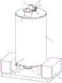
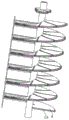
图1是本发明实施例提供的污水处理用沉淀箱的立体结构示意图;Fig. 1 is the schematic diagram of the three-dimensional structure of the sedimentation tank for sewage treatment provided by the embodiment of the present invention;
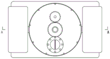
图2是本发明实施例提供的污水处理用沉淀箱的俯视结构示意图;Fig. 2 is a top view structural schematic diagram of a sedimentation tank for sewage treatment provided by an embodiment of the present invention;
图3是本发明实施例提供的图2中A-A部分的剖视结构示意图;Fig. 3 is a schematic cross-sectional structure diagram of part A-A in Fig. 2 provided by an embodiment of the present invention;
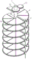
图4是本发明实施例提供的沉淀板和清洁机构的第一视角的结构示意图;Fig. 4 is a structural schematic diagram of a first viewing angle of a precipitation plate and a cleaning mechanism provided by an embodiment of the present invention;
图5是本发明实施例提供的图4中B部分的放大结构示意图;Fig. 5 is an enlarged structural schematic diagram of part B in Fig. 4 provided by an embodiment of the present invention;
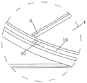
图6是本发明实施例提供的图4中C部分的放大结构示意图;Fig. 6 is a schematic diagram of an enlarged structure of part C in Fig. 4 provided by an embodiment of the present invention;
图7是本发明实施例提供的沉淀板和清洁机构的第二视角的结构示意图;Fig. 7 is a structural schematic diagram of a second viewing angle of a sedimentation plate and a cleaning mechanism provided by an embodiment of the present invention;
图8是本发明实施例提供的箱体底壁处的剖开结构示意图;Fig. 8 is a schematic diagram of a cutaway structure at the bottom wall of a box provided by an embodiment of the present invention;
图9是本发明实施例提供的图8中D部分的放大结构示意图。FIG. 9 is a schematic diagram of an enlarged structure of part D in FIG. 8 provided by an embodiment of the present invention.
图中:1、进水口;2、出水口;3、箱体;4、沉淀板;5、主通道;6、第一通孔;7、管道;71、连接管;8、杂质收集箱;9、阀门;10、第二通孔;20、第三通孔;11、第一电机;12、第一齿轮;13、第二齿轮;14、第一排杂通道;15、滑轨;16、滑块;17、上拨杆;18、下拨杆;19、第二排杂通道;21、挡板;22、第二电机;23、转轴;24、偏心轮。In the figure: 1. Water inlet; 2. Water outlet; 3. Box body; 4. Settling plate; 5. Main channel; 6. First through hole; 7. Pipeline; 71. Connecting pipe; 8. Impurity collection box; 9. Valve; 10. Second through hole; 20. Third through hole; 11. First motor; 12. First gear; 13. Second gear; 14. First miscellaneous discharge channel; 15. Slide rail; 16 , slider; 17, upper lever; 18, lower lever; 19, second miscellaneous channel; 21, baffle; 22, second motor; 23, rotating shaft; 24, eccentric wheel.
具体实施方式Detailed ways
为能进一步了解本发明的发明内容、特点及功效,兹例举以下实施例,并配合附图详细说明如下。In order to further understand the content, features and effects of the present invention, the following examples are given, and detailed descriptions are given below with reference to the accompanying drawings.
下面结合附图对本发明的结构作详细的描述。The structure of the present invention will be described in detail below in conjunction with the accompanying drawings.
请参阅图1-图3,本发明实施例提供的一种污水处理用沉淀箱,包括具有进水口1和出水口2的箱体3,还包括:位于箱体3中的具有上下层次的沉淀板4,且所述沉淀板4之间具有若干预定高度的容纳区域(请参阅图3);所述沉淀板4内部具有主通道5以及与所述主通道5连通的第一通孔6,所述第一通孔6开设于所述沉淀板4的上表面;所述主通道5连通有能启闭的管道7,所述管道7的下端延伸到所述箱体3的外侧。Please refer to Fig. 1-Fig. 3, a kind of sedimentation box for sewage treatment provided by the embodiment of the present invention includes a
在本设置中,污水从进水口1进入箱体3后,被分隔在若干个容纳区域中,在每一个容纳区域中,污水中的沉淀只要落到沉淀板4的上表面即可完成沉淀,而无需落到箱体3的底壁,因此缩短了沉淀所需的行程,提高了沉淀效率。在需要去除沉淀板4上表面的沉淀杂质时,打开管道7,靠近沉淀板4的污水在重力作用下流入第一通孔6,并且带动沉淀板4上表面的沉淀杂质进入第一通孔6,然后依次通过主通道5、管道7,最终排出箱体3,最后关闭管道7,使其他的污水从出水口2排出,进入下一个处理工序。由于将污水分隔在若干个容纳区域中,每个容纳区域中的沉淀堆积不会过高,因此也便于杂质的排出。In this setting, after the sewage enters the
进一步的,对于沉淀板4而言,在一种实施例中,可设置有若干个沉淀板4,所述沉淀板4呈单排或多排排列,位于同一排的沉淀板4上下对齐从而在沉淀板4之间形成容纳区域,通过该设置,可以实现上述目的。Further, for the
在另一种实施例中,请参阅图3和图4,所述箱体3的内腔为圆柱形腔体,所述管道7竖直设置,且和所述箱体3的内腔同轴设置,所述沉淀板4的形状为螺旋形,所述沉淀板4环绕设置在管道7上。In another embodiment, please refer to FIG. 3 and FIG. 4 , the inner cavity of the
通过该设置,一方面,污水注入时,污水可在沉淀板4上旋转下移,从而从上到下清洗沉淀板4上表面,每次注入污水时都能起到冲刷作用;另一方面,该设置占用的水平空间更小。Through this setting, on the one hand, when the sewage is injected, the sewage can rotate and move down on the
需要说明的是,通常的沉淀板4的螺距和外径比例为1:1-2,而在本设置中,沉淀板4的螺距和外径的比例为1:4-10。当螺距和外径的比例高于1:4,此时沉淀板4的螺距较大,沉淀板4的倾斜较大,沉淀板4上的沉淀杂质容易下滑。当螺距和外径的比例低于1:10,此时螺距过小,使容纳区域的高度尺寸较小,一方面,沉淀所需时间不能明显降低,另一方面,在沉淀板4的用料和工艺等方面会造成浪费,且在后续设置中,驱动沉淀板4进行转动的能耗增大。沉淀板4的螺距和外径的比例为1:4-10时,容纳区域的高度适中,并且沉淀板4上的沉淀杂质不易下滑。It should be noted that the ratio of the screw pitch to the outer diameter of the
进一步的,所述沉淀板4的边缘和箱体3内壁贴合。若沉淀板4和箱体3内壁之间具有间隙,则间隙中的沉淀会落到箱体3底壁,行程较长,不利于提高沉淀速度。因此,所述沉淀板4的边缘和箱体3内壁贴合可解决该问题。并且,沉淀板4的上表面可设置为不光滑的面(例如磨砂面),防止沉淀杂质下滑。Further, the edge of the
请参阅图1和图3,所述管道7下端延伸出所述箱体3,所述管道7下端通过连接管71连通有杂质收集箱8,所述连接管71上具有阀门9。Please refer to FIG. 1 and FIG. 3 , the lower end of the
通过该设置,通过阀门9的启闭即可控制管道7的启闭,当沉淀结束后,开启阀门9,即可使箱体3中水带动沉淀板4上的沉淀杂质进入第一通孔6,然后依次通过主通道5、管道7和连接管71进入到杂质收集箱8中,然后关闭阀门9,即可完成杂质的排出。优选的,杂质收集箱8具有若干个,可容纳更多的杂质。在具体实施时,可通过泵(例如污泥泵)来连通管道7和连接管71,从而对管道7产生吸力,便于排出沉淀杂质。Through this setting, the opening and closing of the
示例性的,请参阅图3和图4,所述第一通孔6具有若干个,且设置为条形,且若干个第一通孔6呈环形等距设置。一方面,沉淀板4上表面的沉淀杂质即使下滑,也会滑落到第一通孔6中,进而进入到主通道5中。另一方面,也便于后续设置的清理机构将沉淀板4上的沉淀杂质拨到第一通孔6中,从而便于沉淀杂质的排出。For example, please refer to FIG. 3 and FIG. 4 , there are several first through
请参阅图4和图5,所述沉淀板4的下表面具有若干和所述主通道5连通的第二通孔10,若干所述第二通孔10等距分布。Please refer to FIG. 4 and FIG. 5 , the lower surface of the settling
通过该设置,在一个容纳区域中,污水中的沉淀杂质下沉的同时,污水中的漂浮物杂质会上浮到上一层沉淀板4的下表面,当打开管道7排出沉淀时,水流也可带动漂浮物杂质通过第二通孔10进入到主通道5中,然后经管道7下端排出。通过本设置,不止可以去除沉淀杂质,还能去除漂浮物杂质。并且由于漂浮物杂质也只需要在容纳区间中进行上浮,上浮的行程更小,因此可提高去除漂浮物杂质的速度。Through this setting, in a holding area, while the sedimented impurities in the sewage sink, the floating impurities in the sewage will float up to the lower surface of the upper layer of
需要说明的是,在第一通孔6和第二通孔10的宽度尺寸较大(长度尺寸和宽度尺寸的比例在10:1以下)时,所述第二通孔10和所述第一通孔6交错分布,或者两者之间有部分不对齐,从而不会使大量的沉淀杂质依次通过第一通孔6和第二通孔10而掉落到下一个容纳区间中,也不会使大量的漂浮物杂质依次通过第二通孔10和第一通孔6而上浮到上一个容纳区间中,从而将沉淀和漂浮物的运动空间限制在容纳区域中。It should be noted that when the width dimension of the first through
当然,在第一通孔6和第二通孔10的宽度尺寸较小(长度尺寸和宽度尺寸的比例在10:1以上)时,为了加工第一通孔6和第二通孔10的便捷性,也可使两者对齐,因为第一通孔6和第二通孔10的宽度尺寸较小,杂质穿过的数量在工艺要求之内,不会影响运行。Of course, when the width dimension of the first through
进一步的,所述管道7上方连通有供气件和/或供液件(图中未示出)。Further, an air supply element and/or a liquid supply element (not shown in the figure) communicates above the
通过该设置,第一,可直接将溶解后的絮凝剂通过管道7注入到每一个容纳区域中,提高絮凝剂的注入效率。第二,可反向冲洗第一通孔6和第二通孔10,防止堵塞。第三,可通过供气件向管道7中供气,使气体从第一通孔6中排出,从而可以提高漂浮物的上浮速度(适用于沉淀杂质已经排出的情况下)。在具体实施时,可以单独设置供气件或者供液件,也可通过设置供气件和供液件,两者通过切换阀和管道7的上端连通。供气件和供液件可根据距离的使用需要设置为高压或普通液体泵,或气泵,在此不再赘述。With this arrangement, firstly, the dissolved flocculant can be directly injected into each accommodation area through the
所述管道7的外周面上具有第三通孔20,所述第三通孔20设置有单向阀,允许流体通过管道7流向腔体内,阻止腔体内的流体流入所述管道7内,所述供气件和/或供液件向所述管道7中出入气体和/或液体,所述气体和/或液体从第三通孔20中喷出时,能冲刷所述沉淀板4的上表面和/或下表面。在具体实施时,所述第三通孔20可向不同方向倾斜,从而提高清理面积。The outer peripheral surface of the
请参阅图1和图3,本装置还包括转动驱动机构,用于驱动所述管道7转动;所述转动驱动机构包括第一电机11,所述第一电机11的输出端传动连接有第一齿轮12;所述管道7的外周面固定安装有第二齿轮13,所述第一齿轮12和所述第二齿轮13啮合。Please refer to Fig. 1 and Fig. 3, this device also includes a rotation drive mechanism for driving the rotation of the
例如,所述第一电机11的输出端传动连接有第一齿轮12的设置为:第一电机11的输出端通过变速箱传动连接于第一齿轮12。通过该设置,一方面,能够驱动管道7和沉淀板4转动,另一方面,不会阻碍管道7的上端和供气件和/或供液件通过管道7连接。For example, if the output end of the
沉淀板4转动的优点在于:The advantage that
第一,沉淀板4边缘可设置毛刷,从而在沉淀板4转动时,可以清理箱体3的内壁。请参阅图4-图6,沉淀板4的上边缘设置有和所述主通道5连通的第一排杂通道14,在打开管道7的情况下,沉淀板4转动一圈时可将聚集在箱体3内壁和沉淀板4边缘之间的沉淀杂质排出。并且,也可便于将毛刷清理内壁的杂质排出。优选的,第一通孔6:第二通孔10:第一排杂通道14的出液体积比为4∶2∶1。通过该设置,在排出各项杂质时,可降低对污水的排出量。First, brushes can be arranged on the edge of the
第二,能在箱体3内壁上设置清理机构,通过沉淀板4的转动,拨动沉淀板4上的沉淀杂质和/或沉淀板4下的漂浮物进入到第一通孔6或第二通孔10。例如:Second, a cleaning mechanism can be set on the inner wall of the
请参阅图5和图7,所述清理机构包括具有竖直设置的滑轨15,所述滑轨15上滑动连接有滑块16,所述滑块16上固定连接有上拨杆17和下拨杆18,所述上拨杆17的下表面和所述沉淀板4的上表面贴合,所述下拨杆18的上表面和所述沉淀板4的下表面贴合。Please refer to Fig. 5 and Fig. 7, described clearing mechanism comprises the
通过该设置,在排出杂质时,驱使沉淀板4转动,从而使上拨杆17将沉淀板4的上表面的杂质拨动到第一通孔6中,并且,下拨杆18将沉淀板4下表面的杂质拨动到第二通孔10中,从而便于杂质排出。Through this arrangement, when the impurities are discharged, the
上拨杆17和下拨杆18可设置为橡胶等容易形变和复位的材质,或者拨杆主体采用刚性材质,和沉淀板4贴合的部位为橡胶等容易形变和复位的材质。进一步的,箱体3的内腔表面设置竖直的滑槽,滑块16和滑轨15均设置于滑槽中,因此,不会妨碍沉淀板4和箱体3的内腔表面贴合。The
请参阅图3和图7,所述沉淀板4的下边缘和所述箱体3的底壁上表面贴合,所述沉淀板4的下边缘具有第二排杂通道19,所述第二排杂通道19和所述主通道5连通,通过转动沉淀板4,可将箱体3的底壁上表面的杂质排出,并且还可清理箱体3的底壁上表面。Referring to Fig. 3 and Fig. 7, the lower edge of the settling
进一步的,请参阅图8和图9,所述出水口2上设置有能启闭的挡板21,当所述挡板21闭合于所述出水口2的上端时,所述挡板21上表面和所述箱体3底壁上表面齐平;Further, please refer to FIG. 8 and FIG. 9, the water outlet 2 is provided with a
所述挡板21下侧连接有防水的推动件,用于推动挡板21启闭;The lower side of the
所述污水处理用沉淀箱还包括控制开关,所述控制开关的输出端和所述推动件信号连接,当所述控制开关被触动时,能驱使挡板21开启或关闭。The settling tank for sewage treatment also includes a control switch, the output terminal of the control switch is connected to the push member for signal, and when the control switch is touched, the
通过该设置,在沉淀板4的下边缘清理箱体3底壁上表面的沉淀杂质时,由于设置挡板21,沉淀杂质不会落到出水口2中,当沉淀板4转动一圈清理结束时,拨动控制开关,从而推动件推动挡板21开启,此时可将去除沉淀后的污水从出水口2排出。Through this setting, when cleaning the precipitated impurities on the upper surface of the bottom wall of the
例如,所述推动件包括第二电机22、转轴23和偏心轮24,所述第二电机22固定连接于所述出水口2的外侧,所述转轴23的一端和所述第二电机22的输出端固定连接,所述转轴23通过密封轴承连接于所述出水口2,且所述转轴23的另一端延伸到所述出水口2的外侧,所述偏心轮24固定连接于所述转轴23。所述第二电机22通过转轴23带动偏心轮24转动,从而将挡板21向上推动,挡板21一侧通过弹片和箱体3的底壁上表面连接,因此能被偏心轮24向上推动而倾斜。For example, the pusher includes a
例如,控制开关设置可为接触式的控制开关,设置在箱体3底壁上表面或箱体3底壁,当沉淀板4转动360°时,可将箱体3底壁上的杂质去除,清理后,沉淀板4碰触控制开关,从而使挡板21开启,从而排出污水。For example, the control switch setting can be a contact control switch, which is arranged on the upper surface of the bottom wall of the
本发明的工作原理:Working principle of the present invention:
第一步,使出水口2处于关闭状态,开启进水口1,污水从进水口1进入箱体3,并沿着沉淀板4螺旋下滑,直至灌注到箱体的预定容积,此时,污水被分隔在若干容纳区域中;The first step is to close the water outlet 2 and open the
第二步,通过关闭阀门9,从而将管道7的下端关闭,然后从管道7的上端灌入液体状态的絮凝剂,絮凝剂通过第一通孔6、第二通孔10和第三通孔20灌注到容纳区域中;In the second step, the lower end of the
第三步,开始沉淀,在每一个容纳区域中,污水中的沉淀只要落到沉淀板4的上表面即可完成沉淀,而无需落到箱体3的底壁,因此缩短了沉淀所需的行程,提高了沉淀效率;The third step is to start settling. In each holding area, the settling in the sewage can be completed as long as it falls on the upper surface of the settling
第四步,在需要去除沉淀板4上表面的沉淀杂质时,打开管道7,靠近沉淀板4的污水在重力作用下流入第一通孔6,并且带动沉淀板4上表面的沉淀杂质进入第一通孔6,然后依次通过主通道5、管道7,最终排出箱体3;In the fourth step, when it is necessary to remove the precipitated impurities on the upper surface of the
第五步,关闭管道7,打开出水口2,使沉淀后的污水从出水口2排出。The fifth step is to close the
需要说明的是,在本文中,诸如第一和第二等之类的关系术语仅仅用来将一个实体或者操作与另一个实体或操作区分开来,而不一定要求或者暗示这些实体或操作之间存在任何这种实际的关系或者顺序。而且,术语“包括”、“包含”或者其任何其他变体意在涵盖非排他性的包含,从而使得包括一系列要素的过程、方法、物品或者设备不仅包括那些要素,而且还包括没有明确列出的其他要素,或者是还包括为这种过程、方法、物品或者设备所固有的要素。It should be noted that in this article, relational terms such as first and second are only used to distinguish one entity or operation from another entity or operation, and do not necessarily require or imply that there is a relationship between these entities or operations. There is no such actual relationship or order between them. Furthermore, the term "comprises", "comprises" or any other variation thereof is intended to cover a non-exclusive inclusion such that a process, method, article, or apparatus comprising a set of elements includes not only those elements, but also includes elements not expressly listed. other elements of or also include elements inherent in such a process, method, article, or device.
尽管已经示出和描述了本发明的实施例,对于本领域的普通技术人员而言,可以理解在不脱离本发明的原理和精神的情况下可以对这些实施例进行多种变化、修改、替换和变型,本发明的范围由所附权利要求及其等同物限定。Although the embodiments of the present invention have been shown and described, those skilled in the art can understand that various changes, modifications and substitutions can be made to these embodiments without departing from the principle and spirit of the present invention. and modifications, the scope of the invention is defined by the appended claims and their equivalents.
Claims (9)
Priority Applications (1)
| Application Number | Priority Date | Filing Date | Title |
|---|---|---|---|
| CN202310437044.XA CN116139552B (en) | 2023-04-23 | 2023-04-23 | Sedimentation tank for sewage treatment |
Applications Claiming Priority (1)
| Application Number | Priority Date | Filing Date | Title |
|---|---|---|---|
| CN202310437044.XA CN116139552B (en) | 2023-04-23 | 2023-04-23 | Sedimentation tank for sewage treatment |
Publications (2)
| Publication Number | Publication Date |
|---|---|
| CN116139552A CN116139552A (en) | 2023-05-23 |
| CN116139552B true CN116139552B (en) | 2023-06-27 |
Family
ID=86362202
Family Applications (1)
| Application Number | Title | Priority Date | Filing Date |
|---|---|---|---|
| CN202310437044.XA Active CN116139552B (en) | 2023-04-23 | 2023-04-23 | Sedimentation tank for sewage treatment |
Country Status (1)
| Country | Link |
|---|---|
| CN (1) | CN116139552B (en) |
Families Citing this family (1)
| Publication number | Priority date | Publication date | Assignee | Title |
|---|---|---|---|---|
| CN118925301A (en) * | 2024-07-23 | 2024-11-12 | 湖北安耐吉环保科技有限公司 | A waste lubricating oil regeneration coagulation sedimentation composite equipment |
Citations (2)
| Publication number | Priority date | Publication date | Assignee | Title |
|---|---|---|---|---|
| RU2006248C1 (en) * | 1991-06-24 | 1994-01-30 | Акционерное общество "Новатор" | Vertical settler |
| CN206940517U (en) * | 2017-05-03 | 2018-01-30 | 衢州科创工业设计服务有限公司 | A kind of detention tank with sterilizing function |
Family Cites Families (7)
| Publication number | Priority date | Publication date | Assignee | Title |
|---|---|---|---|---|
| CN101879384B (en) * | 2010-07-15 | 2012-07-18 | 云南大红山管道有限公司 | Process method for high-floater and small-granularity demineralization in iron concentrate transportation |
| US20120195686A1 (en) * | 2011-02-01 | 2012-08-02 | Grant Michael Hardgrave | Drywell retrofit sump insert for storm water treatment |
| CN103803890B (en) * | 2014-03-11 | 2015-10-07 | 山东理工大学 | Ceramic Composite microballon prepares the method for low density oil well cementing cement briquette |
| KR101991810B1 (en) * | 2018-02-08 | 2019-06-21 | 주식회사 두현이엔씨 | Wastewater treatment system having improved removing efficiency of floating matter and scum |
| CN111632408B (en) * | 2020-06-27 | 2024-07-26 | 河南泽衡环保科技股份有限公司 | Totally-enclosed vertical sewage treatment sedimentation tank |
| CN216677096U (en) * | 2021-12-15 | 2022-06-07 | 福建圆通机械工贸有限责任公司 | Sewage treatment and precipitation device for PET bottle flake production without industrial acid neutralization |
| CN218653128U (en) * | 2022-08-27 | 2023-03-21 | 王学良 | Sewage is with deposiing device |
-
2023
- 2023-04-23 CN CN202310437044.XA patent/CN116139552B/en active Active
Patent Citations (2)
| Publication number | Priority date | Publication date | Assignee | Title |
|---|---|---|---|---|
| RU2006248C1 (en) * | 1991-06-24 | 1994-01-30 | Акционерное общество "Новатор" | Vertical settler |
| CN206940517U (en) * | 2017-05-03 | 2018-01-30 | 衢州科创工业设计服务有限公司 | A kind of detention tank with sterilizing function |
Also Published As
| Publication number | Publication date |
|---|---|
| CN116139552A (en) | 2023-05-23 |
Similar Documents
| Publication | Publication Date | Title |
|---|---|---|
| CN208493359U (en) | A kind of novel sedimentation basin | |
| CN209848401U (en) | Sewage treatment sedimentation tank | |
| CN116139552B (en) | Sedimentation tank for sewage treatment | |
| WO2026020973A1 (en) | Wastewater recycling device capable of continuously saving water resources | |
| CN113585440B (en) | Drainage system with treatment facility and drainage control method | |
| CN221333174U (en) | Cyclone sand setting device convenient for discharging | |
| CN214862123U (en) | Special wet dust collector for slag disintegrating pool | |
| CN211912827U (en) | Sewage settling device | |
| CN222358012U (en) | A sewage treatment sedimentation tank | |
| CN222605602U (en) | A sewage treatment pool | |
| CN210078925U (en) | Rotary recoil type inclined plate sedimentation device | |
| CN220078632U (en) | Municipal road concave green belt water collecting and purifying device | |
| CN218944426U (en) | High-efficient swash plate sedimentation tank | |
| CN116005702B (en) | Precipitation well structure | |
| CN110917668A (en) | Precipitation device for sewage treatment | |
| CN117735742A (en) | Aeration sand setting tank capable of efficiently discharging sand | |
| CN117625361A (en) | A highly active probiotic separation device for production | |
| CN214612315U (en) | Desander for oil development | |
| CN208511959U (en) | A sewage treatment tank sludge discharge device | |
| CN211311263U (en) | Septic tank capable of preventing partition wall from blocking water passing opening | |
| CN116272009A (en) | A rapid water intake structure for the upper layer of the mud-water separation sedimentation tank | |
| CN116022986A (en) | A sludge thickening device | |
| CN222550206U (en) | Precision sand removal device | |
| CN222846517U (en) | Water treatment sedimentation tower | |
| CN218755253U (en) | Anaerobic reactor |
Legal Events
| Date | Code | Title | Description |
|---|---|---|---|
| PB01 | Publication | ||
| PB01 | Publication | ||
| SE01 | Entry into force of request for substantive examination | ||
| SE01 | Entry into force of request for substantive examination | ||
| GR01 | Patent grant | ||
| GR01 | Patent grant | ||
| PE01 | Entry into force of the registration of the contract for pledge of patent right |
Denomination of invention: A sedimentation tank for sewage treatment Effective date of registration: 20231101 Granted publication date: 20230627 Pledgee: Yantai financing guarantee Group Co.,Ltd. Pledgor: Yantai Yunfeng Eco-environmental Industry Development Co.,Ltd. Registration number: Y2023980063737 |
|
| PE01 | Entry into force of the registration of the contract for pledge of patent right |