CN116112667A - Method and apparatus for video encoding and decoding using palette mode - Google Patents
Method and apparatus for video encoding and decoding using palette mode Download PDFInfo
- Publication number
- CN116112667A CN116112667A CN202211518329.8A CN202211518329A CN116112667A CN 116112667 A CN116112667 A CN 116112667A CN 202211518329 A CN202211518329 A CN 202211518329A CN 116112667 A CN116112667 A CN 116112667A
- Authority
- CN
- China
- Prior art keywords
- block
- video
- palette
- prediction
- quantization parameter
- Prior art date
- Legal status (The legal status is an assumption and is not a legal conclusion. Google has not performed a legal analysis and makes no representation as to the accuracy of the status listed.)
- Pending
Links
Images


Classifications
-
- H—ELECTRICITY
- H04—ELECTRIC COMMUNICATION TECHNIQUE
- H04N—PICTORIAL COMMUNICATION, e.g. TELEVISION
- H04N19/00—Methods or arrangements for coding, decoding, compressing or decompressing digital video signals
- H04N19/44—Decoders specially adapted therefor, e.g. video decoders which are asymmetric with respect to the encoder
-
- H—ELECTRICITY
- H04—ELECTRIC COMMUNICATION TECHNIQUE
- H04N—PICTORIAL COMMUNICATION, e.g. TELEVISION
- H04N19/00—Methods or arrangements for coding, decoding, compressing or decompressing digital video signals
- H04N19/10—Methods or arrangements for coding, decoding, compressing or decompressing digital video signals using adaptive coding
- H04N19/102—Methods or arrangements for coding, decoding, compressing or decompressing digital video signals using adaptive coding characterised by the element, parameter or selection affected or controlled by the adaptive coding
- H04N19/119—Adaptive subdivision aspects, e.g. subdivision of a picture into rectangular or non-rectangular coding blocks
-
- H—ELECTRICITY
- H04—ELECTRIC COMMUNICATION TECHNIQUE
- H04N—PICTORIAL COMMUNICATION, e.g. TELEVISION
- H04N19/00—Methods or arrangements for coding, decoding, compressing or decompressing digital video signals
- H04N19/10—Methods or arrangements for coding, decoding, compressing or decompressing digital video signals using adaptive coding
- H04N19/102—Methods or arrangements for coding, decoding, compressing or decompressing digital video signals using adaptive coding characterised by the element, parameter or selection affected or controlled by the adaptive coding
- H04N19/124—Quantisation
-
- H—ELECTRICITY
- H04—ELECTRIC COMMUNICATION TECHNIQUE
- H04N—PICTORIAL COMMUNICATION, e.g. TELEVISION
- H04N19/00—Methods or arrangements for coding, decoding, compressing or decompressing digital video signals
- H04N19/10—Methods or arrangements for coding, decoding, compressing or decompressing digital video signals using adaptive coding
- H04N19/102—Methods or arrangements for coding, decoding, compressing or decompressing digital video signals using adaptive coding characterised by the element, parameter or selection affected or controlled by the adaptive coding
- H04N19/132—Sampling, masking or truncation of coding units, e.g. adaptive resampling, frame skipping, frame interpolation or high-frequency transform coefficient masking
-
- H—ELECTRICITY
- H04—ELECTRIC COMMUNICATION TECHNIQUE
- H04N—PICTORIAL COMMUNICATION, e.g. TELEVISION
- H04N19/00—Methods or arrangements for coding, decoding, compressing or decompressing digital video signals
- H04N19/10—Methods or arrangements for coding, decoding, compressing or decompressing digital video signals using adaptive coding
- H04N19/134—Methods or arrangements for coding, decoding, compressing or decompressing digital video signals using adaptive coding characterised by the element, parameter or criterion affecting or controlling the adaptive coding
- H04N19/157—Assigned coding mode, i.e. the coding mode being predefined or preselected to be further used for selection of another element or parameter
-
- H—ELECTRICITY
- H04—ELECTRIC COMMUNICATION TECHNIQUE
- H04N—PICTORIAL COMMUNICATION, e.g. TELEVISION
- H04N19/00—Methods or arrangements for coding, decoding, compressing or decompressing digital video signals
- H04N19/10—Methods or arrangements for coding, decoding, compressing or decompressing digital video signals using adaptive coding
- H04N19/169—Methods or arrangements for coding, decoding, compressing or decompressing digital video signals using adaptive coding characterised by the coding unit, i.e. the structural portion or semantic portion of the video signal being the object or the subject of the adaptive coding
- H04N19/17—Methods or arrangements for coding, decoding, compressing or decompressing digital video signals using adaptive coding characterised by the coding unit, i.e. the structural portion or semantic portion of the video signal being the object or the subject of the adaptive coding the unit being an image region, e.g. an object
- H04N19/176—Methods or arrangements for coding, decoding, compressing or decompressing digital video signals using adaptive coding characterised by the coding unit, i.e. the structural portion or semantic portion of the video signal being the object or the subject of the adaptive coding the unit being an image region, e.g. an object the region being a block, e.g. a macroblock
-
- H—ELECTRICITY
- H04—ELECTRIC COMMUNICATION TECHNIQUE
- H04N—PICTORIAL COMMUNICATION, e.g. TELEVISION
- H04N19/00—Methods or arrangements for coding, decoding, compressing or decompressing digital video signals
- H04N19/10—Methods or arrangements for coding, decoding, compressing or decompressing digital video signals using adaptive coding
- H04N19/169—Methods or arrangements for coding, decoding, compressing or decompressing digital video signals using adaptive coding characterised by the coding unit, i.e. the structural portion or semantic portion of the video signal being the object or the subject of the adaptive coding
- H04N19/182—Methods or arrangements for coding, decoding, compressing or decompressing digital video signals using adaptive coding characterised by the coding unit, i.e. the structural portion or semantic portion of the video signal being the object or the subject of the adaptive coding the unit being a pixel
-
- H—ELECTRICITY
- H04—ELECTRIC COMMUNICATION TECHNIQUE
- H04N—PICTORIAL COMMUNICATION, e.g. TELEVISION
- H04N19/00—Methods or arrangements for coding, decoding, compressing or decompressing digital video signals
- H04N19/10—Methods or arrangements for coding, decoding, compressing or decompressing digital video signals using adaptive coding
- H04N19/169—Methods or arrangements for coding, decoding, compressing or decompressing digital video signals using adaptive coding characterised by the coding unit, i.e. the structural portion or semantic portion of the video signal being the object or the subject of the adaptive coding
- H04N19/184—Methods or arrangements for coding, decoding, compressing or decompressing digital video signals using adaptive coding characterised by the coding unit, i.e. the structural portion or semantic portion of the video signal being the object or the subject of the adaptive coding the unit being bits, e.g. of the compressed video stream
-
- H—ELECTRICITY
- H04—ELECTRIC COMMUNICATION TECHNIQUE
- H04N—PICTORIAL COMMUNICATION, e.g. TELEVISION
- H04N19/00—Methods or arrangements for coding, decoding, compressing or decompressing digital video signals
- H04N19/10—Methods or arrangements for coding, decoding, compressing or decompressing digital video signals using adaptive coding
- H04N19/169—Methods or arrangements for coding, decoding, compressing or decompressing digital video signals using adaptive coding characterised by the coding unit, i.e. the structural portion or semantic portion of the video signal being the object or the subject of the adaptive coding
- H04N19/186—Methods or arrangements for coding, decoding, compressing or decompressing digital video signals using adaptive coding characterised by the coding unit, i.e. the structural portion or semantic portion of the video signal being the object or the subject of the adaptive coding the unit being a colour or a chrominance component
-
- H—ELECTRICITY
- H04—ELECTRIC COMMUNICATION TECHNIQUE
- H04N—PICTORIAL COMMUNICATION, e.g. TELEVISION
- H04N19/00—Methods or arrangements for coding, decoding, compressing or decompressing digital video signals
- H04N19/50—Methods or arrangements for coding, decoding, compressing or decompressing digital video signals using predictive coding
- H04N19/593—Methods or arrangements for coding, decoding, compressing or decompressing digital video signals using predictive coding involving spatial prediction techniques
-
- H—ELECTRICITY
- H04—ELECTRIC COMMUNICATION TECHNIQUE
- H04N—PICTORIAL COMMUNICATION, e.g. TELEVISION
- H04N19/00—Methods or arrangements for coding, decoding, compressing or decompressing digital video signals
- H04N19/70—Methods or arrangements for coding, decoding, compressing or decompressing digital video signals characterised by syntax aspects related to video coding, e.g. related to compression standards
Abstract
An electronic device performs a method for video encoding. The method comprises the following steps: dividing a video frame into a plurality of blocks; determining a quantization parameter for a current block of the plurality of blocks; identifying escape samples in the current block; if it is determined that the quantization parameter is greater than a threshold value: obtaining a reconstructed sample based on the escape sample using a predefined formula; and if it is determined that the quantization parameter is equal to the threshold value: setting the reconstructed samples to values of the escape samples; and encoding information associated with the quantization parameter into a bitstream.
Description
The present application is a divisional application with the application number of "202080071489.5", the application date of "day 08, 14 in 2020", and the title of the invention "method and apparatus for video encoding and decoding using palette mode".
Technical Field
The present application relates generally to video data codec and compression, and more particularly to a method and system for video codec using palette modes.
Background
Various electronic devices support digital video such as digital televisions, laptop or desktop computers, tablet computers, digital cameras, digital recording devices, digital media players, video game consoles, smart phones, video teleconferencing devices, video streaming devices, and the like. These electronic devices transmit, receive, encode, decode, and/or store digital video data by implementing video compression/decompression standards defined by the MPEG-4, ITU-T H.263, ITU-T H.264/MPEG-4 part 10, advanced Video Codec (AVC), high Efficiency Video Codec (HEVC), and common video codec (VVC) standards. Video compression typically includes performing spatial (intra) prediction and/or temporal (inter) prediction to reduce or eliminate redundancy inherent in video data. For block-based video coding, a video frame is partitioned into one or more slices, each slice having a plurality of video blocks, which may also be referred to as a Coding Tree Unit (CTU). Each CTU may contain one Coding Unit (CU) or be recursively split into smaller CUs until a predefined minimum CU size is reached. Each CU (also referred to as a leaf CU) contains one or more Transform Units (TUs), and each CU also contains one or more Prediction Units (PUs). Each CU may be encoded in intra mode, inter mode, or IBC mode. Video blocks in an intra-codec (I) slice of a video frame are encoded using spatial prediction, which is relative to reference samples in neighboring blocks within the same video frame. Video blocks in inter-codec (P or B) slices of a video frame may use spatial prediction, relative to reference samples in neighboring blocks in the same video frame, or temporal prediction, relative to reference samples in other previous and/or future reference videos.
A prediction block for a current video block to be encoded is generated based on spatial prediction or temporal prediction of a reference block (e.g., a neighboring block) that has been previously encoded. The process of finding the reference block may be accomplished by a block matching algorithm. Residual data, which represents pixel differences between a current block to be encoded and a prediction block, is referred to as a residual block or a prediction error. The inter-coded block is encoded according to a motion vector and a residual block, the motion vector pointing to a reference block in a reference frame forming the prediction block. The process of determining motion vectors is commonly referred to as motion estimation. The intra-coded block is coded according to an intra-prediction mode and a residual block. For further compression, the residual block is transformed from the pixel domain to a transform domain (e.g., frequency domain) to generate residual transform coefficients, which may then be quantized. These quantized transform coefficients, initially arranged in a two-dimensional array, may be scanned to produce a one-dimensional vector of transform coefficients, and then entropy encoded into a video bitstream to achieve even greater compression.
The encoded video bitstream is then stored in a computer readable storage medium (e.g., flash memory) for access by another electronic device having digital video capabilities, or transmitted directly to the electronic device in a wired or wireless manner. The electronic device then performs video decompression (which is the reverse of the video compression described above) by: for example, parsing the encoded video bitstream to obtain syntax elements from the bitstream, and reconstructing the digital video data from the encoded video bitstream to its original format based at least in part on the syntax elements obtained from the bitstream, and the electronic device rendering the reconstructed digital video data on a display of the electronic device.
As digital video quality changes from high definition to 4k×2K or even 8k×4K, the amount of video data to be encoded/decoded increases exponentially. It is a continuing challenge to more efficiently encode/decode video data while maintaining the image quality of the decoded video data.
Disclosure of Invention
Embodiments are described herein in connection with video data encoding and decoding, and in particular, embodiments relate to systems and methods for video encoding and decoding using palette modes.
According to a first aspect of the present application, a method for video coding, comprises: dividing a video frame into a plurality of blocks; determining a quantization parameter for a current block of the plurality of blocks; identifying escape samples in the current block; if it is determined that the quantization parameter is greater than a threshold value: obtaining a reconstructed sample based on the escape sample using a predefined formula; and if it is determined that the quantization parameter is equal to the threshold value: setting the reconstructed samples to values of the escape samples; and encoding information associated with the quantization parameter into a bitstream.
According to a second aspect of the present application, an electronic device comprises: one or more processing units, a memory, and a plurality of programs stored in the memory. These programs, when executed by one or more processing units, cause the electronic device to perform the method for video encoding as described above.
According to a third aspect of the present application, a non-transitory computer readable storage medium stores a plurality of programs for execution by an electronic device having one or more processing units. These programs, when executed by one or more processing units, cause the electronic device to perform the method for video encoding as described above.
Drawings
The accompanying drawings, which are included to provide a further understanding of the embodiments and are incorporated in and constitute a part of this specification, illustrate the described embodiments and together with the description serve to explain the principles. Like reference numerals designate corresponding parts.
Fig. 1 is a block diagram illustrating an exemplary video encoding and decoding system according to some embodiments of the present disclosure.
Fig. 2 is a block diagram illustrating an exemplary video encoder according to some embodiments of the present disclosure.
Fig. 3 is a block diagram illustrating an exemplary video decoder according to some embodiments of the present disclosure.
Fig. 4A-4E are block diagrams illustrating how a frame is recursively partitioned into multiple video blocks of different sizes and shapes according to some embodiments of the present disclosure.
Fig. 5 is a block diagram illustrating an example of determining and using a palette table to encode and decode video data according to some embodiments of the present disclosure.
Fig. 6 is a flowchart illustrating an exemplary process by which a video decoder implements techniques for decoding video data using a palette-based scheme, according to some embodiments of the present disclosure.
Detailed Description
Reference will now be made in detail to the present embodiments, examples of which are illustrated in the accompanying drawings. In the following detailed description, numerous specific, non-limiting details are set forth to provide an understanding of the subject matter presented herein. It will be apparent, however, to one skilled in the art that various alternatives can be used without departing from the scope of the claims, and the subject matter can be practiced without these specific details. For example, it will be apparent to one of ordinary skill in the art that the subject matter presented herein may be implemented on many types of electronic devices having digital video capabilities.
Fig. 1 is a block diagram illustrating an exemplary system 10 for encoding and decoding video blocks in parallel according to some embodiments of the present disclosure. As shown in fig. 1, the system 10 includes a source device 12, the source device 12 generating and encoding video data that is subsequently decoded by a target device 14. Source device 12 and destination device 14 may comprise any of a wide variety of electronic devices including desktop or laptop computers, tablet computers, smart phones, set-top boxes, digital televisions, cameras, display devices, digital media players, video game consoles, video streaming devices, and the like. In some implementations, the source device 12 and the target device 14 are equipped with wireless communication capabilities.
In some implementations, the target device 14 may receive encoded video data to be decoded via the link 16. Link 16 may comprise any type of communication medium or device capable of moving encoded video data from source device 12 to destination device 14. In one example, link 16 may include a communication medium to enable source device 12 to transmit encoded video data directly to destination device 14 in real-time. The encoded video data may be modulated according to a communication standard, such as a wireless communication protocol, and transmitted to the target device 14. The communication medium may include any wireless or wired communication medium such as a Radio Frequency (RF) spectrum or one or more physical transmission lines. The communication medium may form part of a packet-based network, such as a local area network, a wide area network, or a global network, such as the internet. The communication medium may include routers, switches, base stations, or any other equipment that may be helpful in facilitating communication from source device 12 to destination device 14.
In some other implementations, encoded video data may be transferred from output interface 22 to storage device 32. The encoded video data in the storage device 32 may then be accessed by the target device 14 via the input interface 28. Storage device 32 may include any of a variety of distributed data storage media or locally accessed data storage media such as hard drives, blu-ray discs, DVDs, CD-ROMs, flash memory, volatile or non-volatile memory, or any other suitable digital storage media for storing encoded video data. In another example, storage device 32 may correspond to a file server or another intermediate storage device that may hold encoded video data generated by source device 12. The target device 14 may access the stored video data from the storage device 32 via streaming or download. The file server may be any type of computer capable of storing encoded video data and transmitting the encoded video data to the target device 14. Exemplary file servers include web servers (e.g., for websites), FTP servers, network Attached Storage (NAS) devices, or local disk drives. The target device 14 may access the encoded video data through any standard data connection including a wireless channel (e.g., wi-Fi connection), a wired connection (e.g., DSL, cable modem, etc.), or a combination of both, suitable for accessing the encoded video data stored on the file server. The transmission of encoded video data from storage device 32 may be streaming, download, or a combination of both.
As shown in fig. 1, source device 12 includes a video source 18, a video encoder 20, and an output interface 22. Video source 18 may include a source such as a video capture device, for example, a video camera, a video archive containing previously captured video, a video feed interface for receiving video from a video content provider, and/or a computer graphics system for generating computer graphics data as source video, or a combination of such sources. As one example, if video source 18 is a video camera of a security monitoring system, source device 12 and target device 14 may form a camera phone or video phone. However, the embodiments described in this application may be generally applicable to video codecs and may be applied to wireless applications and/or wired applications.
The captured, pre-captured, or computer-generated video may be encoded by video encoder 20. The encoded video data may be transmitted directly to the target device 14 via the output interface 22 of the source device 12. The encoded video data may also (or alternatively) be stored on the storage device 32 for subsequent access by the target device 14 or other device for decoding and/or playback. Output interface 22 may further include a modem and/or a transmitter.
The target device 14 includes an input interface 28, a video decoder 30, and a display device 34. Input interface 28 may include a receiver and/or modem and receives encoded video data over link 16. The encoded video data transmitted over link 16 or provided on storage device 32 may include various syntax elements that are generated by video encoder 20 for use by video decoder 30 in decoding the video data. Such syntax elements may be included in encoded video data transmitted over a communication medium, stored on a storage medium, or stored on a file server.
In some implementations, the target device 14 may include a display device 34, and the display device 34 may be an integrated display device and an external display device configured to communicate with the target device 14. The display device 34 displays the decoded video data to a user and may include any of a variety of display devices, such as a Liquid Crystal Display (LCD), a plasma display, an Organic Light Emitting Diode (OLED) display, or another type of display device.
Video encoder 20 and video decoder 30 may operate in accordance with proprietary standards or industry standards, such as section 10 of VVC, HEVC, MPEG-4, advanced Video Codec (AVC), or extensions to such standards. It should be understood that the present application is not limited to a particular video codec/decoding standard and may be applicable to other video codec/decoding standards. It is generally contemplated that video encoder 20 of source device 12 may be configured to encode video data according to any of these current or future standards. Similarly, it is also generally contemplated that the video decoder 30 of the target device 14 may be configured to decode video data according to any of these current or future standards.
Video encoder 20 and video decoder 30 may each be implemented as any of a variety of suitable encoder circuitry, such as one or more microprocessors, digital Signal Processors (DSPs), application Specific Integrated Circuits (ASICs), field Programmable Gate Arrays (FPGAs), discrete logic, software, hardware, firmware or any combinations thereof. When implemented in part in software, the electronic device can store instructions for the software in a suitable non-transitory computer-readable medium and execute the instructions in hardware using one or more processors to perform the video codec/decoding operations disclosed in the present disclosure. Each of video encoder 20 and video decoder 30 may be included in one or more encoders or decoders, any of which may be integrated as part of a combined encoder/decoder (CODEC) in the respective device.
Fig. 2 is a block diagram illustrating an exemplary video encoder 20 according to some embodiments described in this application. Video encoder 20 may perform intra-and inter-prediction coding of video blocks within video frames. Intra-prediction codec relies on spatial prediction to reduce or eliminate spatial redundancy in video data within a given video frame or picture. Inter-prediction codec relies on temporal prediction to reduce or eliminate temporal redundancy in video data within adjacent video frames or pictures of a video sequence.
As shown in fig. 2, video encoder 20 includes a video data memory 40, a prediction processing unit 41, a Decoded Picture Buffer (DPB) 64, an adder 50, a transform processing unit 52, a quantization unit 54, and an entropy encoding unit 56. The prediction processing unit 41 further includes a motion estimation unit 42, a motion compensation unit 44, a segmentation unit 45, an intra prediction processing unit 46, and an intra Block Copy (BC) unit 48. In some implementations, video encoder 20 also includes an inverse quantization unit 58, an inverse transform processing unit 60, and an adder 62 for video block reconstruction. A deblocking filter (not shown) may be located between adder 62 and DPB 64 to filter block boundaries to remove blocking artifacts from the reconstructed video. In addition to the deblocking filter, a loop filter (not shown) may be used to filter the output of adder 62. Video encoder 20 may take the form of, or be divided among, one or more of the fixed hardware units or programmable hardware units shown.
Video data memory 40 may store video data to be encoded by components of video encoder 20. The video data in video data store 40 may be obtained, for example, from video source 18. DPB 64 is a buffer that stores reference video data for use by video encoder 20 in encoding the video data (e.g., in intra-or inter-prediction codec mode). Video data memory 40 and DPB 64 may be formed from any of a variety of memory devices. In various examples, video data memory 40 may be on-chip with other components of video encoder 20, or off-chip with respect to those components.
As shown in fig. 2, after receiving video data, a dividing unit 45 within the prediction processing unit 41 divides the video data into video blocks. The partitioning may also include partitioning the video frame into slices, tiles (tiles), or other larger Codec Units (CUs) according to a predefined splitting structure associated with the video data, such as a quadtree structure. A video frame may be divided into a plurality of video blocks (or a set of video blocks, referred to as tiles). The prediction processing unit 41 may select one of a plurality of possible prediction codec modes, such as one of a plurality of intra-prediction codec modes or one of a plurality of inter-prediction codec modes, for the current video block based on the error result (e.g., codec rate and distortion level). The prediction processing unit 41 may provide the resulting intra or inter prediction codec block to the adder 50 to generate a residual block and to the adder 62 to reconstruct the encoded block for subsequent use as part of a reference frame. Prediction processing unit 41 also provides syntax elements, such as motion vectors, intra mode indicators, partition information, and other such syntax information, to entropy encoding unit 56.
To select an appropriate intra-prediction codec mode for the current video block, intra-prediction processing unit 46 within prediction processing unit 41 may perform intra-prediction codec for the current video block with respect to one or more neighboring blocks in the same frame as the current block to be encoded to provide spatial prediction. Motion estimation unit 42 and motion compensation unit 44 within prediction processing unit 41 perform inter-prediction codec of the current video block with respect to one or more prediction blocks in one or more reference frames to provide temporal prediction. Video encoder 20 may perform multiple codec passes, for example, to select an appropriate codec mode for each block of video data.
In some implementations, motion estimation unit 42 determines an inter-prediction mode for the current video frame by generating a motion vector from a predetermined pattern within the sequence of video frames, the motion vector indicating a displacement of a Prediction Unit (PU) of a video block within the current video frame relative to a prediction block within a reference video frame. The motion estimation performed by the motion estimation unit 42 is a process of generating a motion vector that estimates motion for a video block. The motion vector, for example, may indicate the displacement of a video block PU within a current video frame or picture relative to a prediction block within a reference frame (or other coded unit) relative to a current block being coded within the current frame (or other coded unit). The predetermined pattern may designate video frames in the sequence as P-frames or B-frames. The intra BC unit 48 may determine the vector (e.g., block vector) for intra BC codec in a manner similar to the determination of the motion vector for inter prediction by the motion estimation unit 42, or may utilize the motion estimation unit 42 to determine the block vector.
A prediction block is a block of a reference frame that is considered to closely match the PU of the video block to be encoded in terms of pixel differences, which may be determined by the Sum of Absolute Differences (SAD), sum of Squared Differences (SSD), or other difference metric. In some implementations, video encoder 20 may calculate values for sub-integer pixel positions of reference frames stored in DPB 64. For example, video encoder 20 may interpolate values for one-quarter pixel positions, one-eighth pixel positions, or other fractional pixel positions of the reference frame. Accordingly, the motion estimation unit 42 may perform a motion search with respect to the full pixel position and the fractional pixel position, and output a motion vector having fractional pixel accuracy.
Motion estimation unit 42 calculates motion vectors for PUs of video blocks in an inter-prediction codec frame by: the location of the PU is compared to the location of the predicted block of the reference frame selected from the first reference frame list (list 0) or the second reference frame list (list 1), each of which identifies one or more reference frames stored in DPB 64. The motion estimation unit 42 sends the calculated motion vector to the motion compensation unit 44 and then to the entropy encoding unit 56.
The motion compensation performed by the motion compensation unit 44 may involve acquiring or generating a prediction block based on the motion vector determined by the motion estimation unit 42. Upon receiving the motion vector for the PU of the current video block, motion compensation unit 44 may locate the prediction block to which the motion vector points in one of the reference frame lists, retrieve the prediction block from DPB 64, and forward the prediction block to adder 50. Adder 50 then forms a residual video block of pixel differences by subtracting the pixel values of the prediction block provided by motion compensation unit 44 from the pixel values of the current video block being encoded. The pixel differences forming the residual video block may include a luma difference component or a chroma difference component or both. Motion compensation unit 44 may also generate syntax elements associated with the video blocks of the video frames for use by video decoder 30 in decoding the video blocks of the video frames. The syntax elements may include, for example, syntax elements defining motion vectors used to identify the prediction block, any flags indicating prediction modes, or any other syntax information described herein. Note that the motion estimation unit 42 and the motion compensation unit 44 may be highly integrated, but are illustrated separately for conceptual purposes.
In some implementations, the intra BC unit 48 may generate vectors and obtain prediction blocks in a similar manner as described above in connection with the motion estimation unit 42 and the motion compensation unit 44, but these prediction blocks are located in the same frame as the current block being encoded and decoded, and these vectors are referred to as block vectors rather than motion vectors. In particular, the intra BC unit 48 may determine an intra prediction mode for encoding the current block. In some examples, intra BC unit 48 may encode the current block using various intra prediction modes, e.g., during multiple separate encoding passes, and test their performance through rate-distortion analysis. Next, the intra BC unit 48 may select an appropriate intra prediction mode from among the various tested intra prediction modes to use and generate the intra mode indicator accordingly. For example, the intra BC unit 48 may calculate rate distortion values using rate distortion analysis for various tested intra prediction modes, and select the intra prediction mode having the best rate distortion characteristics among the tested modes to use as the appropriate intra prediction mode. Rate-distortion analysis typically determines the amount of distortion (or error) between an encoded block and the original uncoded block encoded to produce the encoded block, as well as the bit rate (i.e., number of bits) used to produce the encoded block. The intra BC unit 48 may calculate the ratio from the distortion and rate for the various encoded blocks to determine which intra prediction mode exhibits the best rate distortion value for the block.
In other examples, intra BC unit 48 may use motion estimation unit 42 and motion compensation unit 44, in whole or in part, to perform such functions for intra BC prediction in accordance with implementations described herein. In either case, for intra block copying, the prediction block may be a block that is considered to closely match the block to be encoded in terms of pixel differences, which may be determined by Sum of Absolute Differences (SAD), sum of Squared Differences (SSD), or other difference metric, and the identification of the prediction block may include calculation of a value for a sub-integer pixel location.
Whether the prediction block is from the same frame according to intra prediction or from a different frame according to inter prediction, video encoder 20 may form a residual video block by: the pixel values of the prediction block are subtracted from the pixel values of the current video block being encoded and decoded, thereby forming pixel difference values. The pixel differences forming the residual video block may include both a luma component difference and a chroma component difference.
As an alternative to inter prediction performed by the motion estimation unit 42 and the motion compensation unit 44, or intra block copy prediction performed by the intra BC unit 48, as described above, the intra prediction processing unit 46 may intra predict the current video block. In particular, intra-prediction processing unit 46 may determine an intra-prediction mode for encoding the current block. To this end, intra-prediction processing unit 46 may encode the current block using various intra-prediction modes, for example, during multiple separate encoding passes, and intra-prediction processing unit 46 (or a mode selection unit in some examples) may select an appropriate intra-prediction mode to use from among the tested intra-prediction modes. Intra-prediction processing unit 46 may provide entropy encoding unit 56 with information indicating the selected intra-prediction mode for the block. Entropy encoding unit 56 may encode information in the bitstream that indicates the selected intra-prediction mode.
After the prediction processing unit 41 determines a prediction block for the current video block via inter prediction or intra prediction, the adder 50 forms a residual video block by subtracting the prediction block from the current video block. The residual video data in the residual block may be included in one or more Transform Units (TUs) and provided to transform processing unit 52. The transform processing unit 52 transforms the residual video data into residual transform coefficients using a transform, such as a Discrete Cosine Transform (DCT) or a conceptually similar transform.
The transform processing unit 52 may send the resulting transform coefficients to the quantization unit 54. The quantization unit 54 quantizes the transform coefficient to further reduce the bit rate. The quantization process may also reduce the bit depth associated with some or all of the coefficients. The quantization level may be modified by adjusting quantization parameters. In some examples, quantization unit 54 may then perform a scan of a matrix including the quantized transform coefficients. Alternatively, entropy encoding unit 56 may perform the scan.
After quantization, entropy encoding unit 56 entropy encodes the quantized transform coefficients into a video bitstream using, for example, context Adaptive Variable Length Coding (CAVLC), context Adaptive Binary Arithmetic Coding (CABAC), syntax-based context adaptive binary arithmetic coding (SBAC), probability Interval Partitioning Entropy (PIPE) coding, or another entropy encoding method or technique. The encoded bitstream may then be sent to video decoder 30 or archived in storage device 32 for later transmission to video decoder 30 or retrieval by video decoder 30. Entropy encoding unit 56 may also entropy encode motion vectors and other syntax elements for the current video frame being encoded.
Adder 62 adds the reconstructed residual block to the motion compensated prediction block generated by motion compensation unit 44 to generate a reference block for storage in DPB 64. The reference block may then be used as a prediction block by the intra BC unit 48, the motion estimation unit 42, and the motion compensation unit 44 to inter-predict another video block in a subsequent video frame.
Fig. 3 is a block diagram illustrating an exemplary video decoder 30 according to some embodiments of the present application. Video decoder 30 includes video data memory 79, entropy decoding unit 80, prediction processing unit 81, inverse quantization unit 86, inverse transform processing unit 88, adder 90, and DPB 92. The prediction processing unit 81 further includes a motion compensation unit 82, an intra prediction processing unit 84, and an intra BC unit 85. Video decoder 30 may perform a decoding process that is substantially reciprocal to the encoding process described above with respect to video encoder 20 in connection with fig. 2. For example, the motion compensation unit 82 may generate prediction data based on the motion vector received from the entropy decoding unit 80, and the intra prediction unit 84 may generate prediction data based on the intra prediction mode indicator received from the entropy decoding unit 80.
In some examples, the elements of video decoder 30 may be tasked to perform embodiments of the present application. Further, in some examples, embodiments of the present disclosure may be divided among one or more units of video decoder 30. For example, the intra BC unit 85 may perform embodiments of the present application alone, or in combination with other units of the video decoder 30 (such as the motion compensation unit 82, the intra prediction processing unit 84, and the entropy decoding unit 80). In some examples, video decoder 30 may not include intra BC unit 85, and the functions of intra BC unit 85 may be performed by other components of prediction processing unit 81 (such as motion compensation unit 82).
Video data memory 79 may store video data, such as an encoded video bitstream, to be decoded by other components of video decoder 30. The video data stored in video data storage 79 may be obtained, for example, from storage device 32, from a local video source such as a camera, via wired or wireless network communication of video data, or by accessing a physical data storage medium such as a flash drive or hard disk. The video data memory 79 may include a Coded Picture Buffer (CPB) that stores encoded video data from an encoded video bitstream. Decoded Picture Buffer (DPB) 92 of video decoder 30 stores reference video data for use when video decoder 30 decodes video data, e.g., in an intra-or inter-prediction codec mode. Video data memory 79 and DPB 92 may be formed from any of a variety of memory devices, such as Dynamic Random Access Memory (DRAM), including Synchronous DRAM (SDRAM), magnetoresistive RAM (MRAM), resistive RAM (RRAM), or other types of memory devices. For purposes of illustration, video data memory 79 and DPB 92 are depicted in fig. 3 as two different components of video decoder 30. It will be apparent to those skilled in the art that video data memory 79 and DPB 92 may be provided by the same memory device or separate memory devices. In some examples, video data memory 79 may be on-chip with other components of video decoder 30, or off-chip with respect to those components.
During the decoding process, video decoder 30 receives an encoded video bitstream that represents video blocks of encoded video frames and associated syntax elements. Video decoder 30 may receive syntax elements at the video frame level and/or the video block level. Entropy decoding unit 80 of video decoder 30 entropy decodes the bitstream to generate quantized coefficients, motion vectors or intra-prediction mode indicators, and other syntax elements. Entropy decoding unit 80 then forwards the motion vectors and other syntax elements to prediction processing unit 81.
When a video frame is encoded as an intra-prediction codec (I) frame, or used for an intra-coding prediction block in other types of frames, the intra-prediction processing unit 84 of the prediction processing unit 81 may generate prediction data for a video block of the current video frame based on the signaled intra-prediction mode and reference data from a previously decoded block of the current frame.
When a video frame is encoded as an inter-prediction codec (i.e., B or P) frame, the motion compensation unit 82 of the prediction processing unit 81 generates one or more prediction blocks for a video block of the current video frame based on the motion vector and other syntax elements received from the entropy decoding unit 80. Each of the prediction blocks may be generated from a reference frame within one of the reference frame lists. Video decoder 30 may construct a list of reference frames, i.e., list 0 and list 1, based on the reference frames stored in DPB 92 using a default construction technique.
In some examples, when a video block is encoded according to the intra BC mode described herein, intra BC unit 85 of prediction processing unit 81 generates a prediction block for the current video block based on the block vector and other syntax elements received from entropy decoding unit 80. The prediction block may be within a reconstructed region of the same picture as the current video block defined by video encoder 20.
The motion compensation unit 82 and/or the intra BC unit 85 determine prediction information for the video block of the current video frame by parsing the motion vector and other syntax elements, and then use the prediction information to generate a prediction block for the current video block being decoded. For example, motion compensation unit 82 uses some of the received syntax elements to determine a prediction mode (e.g., intra-prediction or inter-prediction) for encoding and decoding a video block of a video frame, an inter-prediction frame type (e.g., B or P), construction information for one or more reference frame lists for the frame, motion vectors for each inter-prediction encoded video block of the frame, inter-prediction states for each inter-prediction encoded video block of the frame, and other information for decoding the video block in the current video frame.
Similarly, the intra BC unit 85 may use some of the received syntax elements, such as flags, to determine which video blocks of the frame the current video block was predicted using intra BC mode, the construction information of which video blocks of the frame are within the reconstruction region and should be stored in the DPB in 92, the block vector for each intra BC predicted video block of the frame, the intra BC prediction status for each intra BC predicted video block of the frame, and other information for decoding the video blocks in the current video frame.
Inverse quantization unit 86 dequantizes quantized transform coefficients provided in the bitstream and entropy decoded by entropy decoding unit 80 using the same quantization parameters calculated by video encoder 20 for each video block in the video frame to determine a degree of quantization. The inverse transform processing unit 88 applies an inverse transform (e.g., an inverse DCT, an inverse integer transform, or a conceptually similar inverse transform process) to the transform coefficients to reconstruct the residual block in the pixel domain.
After the motion compensation unit 82 or the intra BC unit 85 generates a prediction block for the current video block based on the vector and other syntax elements, the adder 90 reconstructs the decoded video block for the current video block by adding the residual block from the inverse transform processing unit 88 to the corresponding prediction block generated by the motion compensation unit 82 and the intra BC unit 85. An in-loop filter (not shown) may be located between adder 90 and DPB 92 to further process the decoded video blocks. The decoded video blocks in a given frame are then stored in DPB 92, DPB 92 storing reference frames for subsequent motion compensation of the next video block. DPB 92, or a memory device separate from DPB 92, may also store decoded video for later presentation on a display device, such as display device 34 of fig. 1.
In a typical video codec process, a video sequence generally includes an ordered set of frames or pictures. Each frame may include three sample arrays, denoted SL, SCb, and SCr. SL is a two-dimensional array of luminance samples. SCb is a two-dimensional array of Cb chroma samples. SCr is a two-dimensional array of Cr chroma samples. In other examples, the frame may be monochromatic and thus include only one two-dimensional array of luminance samples.
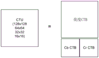
As shown in fig. 4A, video encoder 20 (or more specifically, partitioning unit 45) generates an encoded representation of a frame by first partitioning the frame into a set of Codec Tree Units (CTUs). A video frame may include an integer number of CTUs ordered consecutively in raster scan order from left to right and top to bottom. Each CTU is the largest logical codec unit and the width and height of the CTU are signaled by the video encoder 20 in the sequence parameter set such that all CTUs in the video sequence have the same size, i.e. one of 128 x 128, 64 x 64, 32 x 32 and 16 x 16. It should be noted that the present application is not necessarily limited to a particular size. As shown in fig. 4B, each CTU may include one Codec Tree Block (CTB) of luma samples, two corresponding codec tree blocks of chroma samples, and syntax elements for encoding and decoding samples of the codec tree blocks. Syntax elements describe the nature of the different types of units of the pixel block being encoded and how the video sequence may be reconstructed at video decoder 30, including inter-or intra-prediction, intra-prediction modes, motion vectors, and other parameters. In a monochrome picture or a picture having three separate color planes, a CTU may include a single codec tree block and syntax elements for encoding and decoding samples of the codec tree block. The codec tree block may be an nxn block of samples.
To achieve better performance, video encoder 20 may recursively perform tree partitioning, such as binary tree partitioning, trigeminal tree partitioning, quadtree partitioning, or a combination thereof, on the coded tree blocks of CTUs and divide the CTUs into smaller Codec Units (CUs). As depicted in fig. 4C, a 64 x 64 CTU 400 is first divided into four smaller CUs, each having a block size of 32 x 32. Of the four smaller CUs, both CUs 410 and 420 are divided into four 16×16 CUs by block size. Both 16 x 16 CUs 430 and 440 are further divided into four 8 x 8 CUs by block size. Fig. 4D depicts a quadtree data structure showing the end result of the segmentation process of CTU 400 as depicted in fig. 4C, each leaf node of the quadtree corresponding to one CU of a respective size ranging from 32 x 32 to 8 x 8. As with the CTU depicted in fig. 4B, each CU may include a Coding Block (CB) of luma samples and two corresponding coding blocks of chroma samples of the same-size frame, and syntax elements for coding the samples of the coding blocks. In a monochrome picture or a picture having three separate color planes, a CU may include a single codec block and syntax structures for encoding and decoding samples of the codec block. It should be noted that the quadtree partitions depicted in fig. 4C and 4D are for illustration purposes only, and that one CTU may be split into multiple CUs based on quadtree partitions/trigeminal partitions/binary tree partitions to accommodate different local characteristics. In a multi-type tree structure, one CTU is partitioned by a quadtree structure, and each quadtree leaf CU may be further partitioned by a binary and trigeminal tree structure. As shown in fig. 4E, there are five segmentation types, namely, a quad segmentation, a horizontal binary segmentation, a vertical binary segmentation, a horizontal trigeminal segmentation, and a vertical trigeminal segmentation.
In some implementations, video encoder 20 may further partition the codec blocks of the CU into one or more mxn Prediction Blocks (PB). The prediction block is a rectangular (square or non-square) block of samples on which the same (inter or intra) prediction is applied. A Prediction Unit (PU) of a CU may include a prediction block of luma samples, two corresponding prediction blocks of chroma samples, and syntax elements for predicting the prediction block. In a monochrome picture or a picture having three separate color planes, a PU may include a single prediction block and syntax structures for predicting the prediction block. Video encoder 20 may generate a predicted luma block, a predicted Cb block, and a predicted Cr block for the luma prediction block, the Cb prediction block, and the Cr prediction block of each PU of the CU.
Video encoder 20 may use intra-prediction or inter-prediction to generate the prediction block for the PU. If video encoder 20 uses intra-prediction to generate the prediction block of the PU, video encoder 20 may generate the prediction block of the PU based on decoded samples of the frame associated with the PU. If video encoder 20 uses inter prediction to generate the prediction block of the PU, video encoder 20 may generate the prediction block of the PU based on decoded samples of one or more frames other than the frame associated with the PU.
After video encoder 20 generates the predicted luma block, the predicted Cb block, and the predicted Cr block for the one or more PUs of the CU, video encoder 20 may generate a luma residual block for the CU by subtracting the predicted luma block of the CU from its original luma codec block such that each sample in the luma residual block of the CU indicates a difference between a luma sample in one of the predicted luma blocks of the CU and a corresponding sample in the original luma codec block of the CU. Similarly, video encoder 20 may generate Cb residual blocks and Cr residual blocks for the CU, respectively, such that each sample in the Cb residual block of the CU indicates a difference between a Cb sample in one of the predicted Cb blocks of the CU and a corresponding sample in the original Cb codec block of the CU, and each sample in the Cr residual block of the CU may indicate a difference between a Cr sample in one of the predicted Cr blocks of the CU and a corresponding sample in the original Cr codec block of the CU.
Further, as shown in fig. 4C, video encoder 20 may use quadtree partitioning to decompose the luma residual block, the Cb residual block, and the Cr residual block of the CU into one or more luma transform blocks, cb transform blocks, and Cr transform blocks. A transform block is a rectangular (square or non-square) block of samples to which the same transform is applied. A Transform Unit (TU) of a CU may include a transform block of luma samples, two corresponding transform blocks of chroma samples, and syntax elements for transforming the transform block samples. Thus, each TU of a CU may be associated with a luma transform block, a Cb transform block, and a Cr transform block. In some examples, the luma transform block associated with a TU may be a sub-block of a luma residual block of a CU. The Cb transform block may be a sub-block of a Cb residual block of the CU. The Cr transform block may be a sub-block of a Cr residual block of the CU. In a monochrome picture or a picture having three separate color planes, a TU may comprise a single transform block and syntax structures for transforming the samples of the transform block.
Video encoder 20 may apply one or more transforms to the luma transform block of the TU to generate a luma coefficient block for the TU. The coefficient block may be a two-dimensional array of transform coefficients. The transform coefficients may be scalar quantities. Video encoder 20 may apply one or more transforms to the Cb transform block of the TU to generate a Cb coefficient block for the TU. Video encoder 20 may apply one or more transforms to the Cr transform blocks of the TUs to generate Cr coefficient blocks for the TUs.
After generating the coefficient block (e.g., the luma coefficient block, the Cb coefficient block, or the Cr coefficient block), video encoder 20 may quantize the coefficient block. Quantization generally refers to a process in which transform coefficients are quantized to potentially reduce the amount of data used to represent the transform coefficients, thereby providing further compression. After video encoder 20 quantizes the coefficient block, video encoder 20 may entropy encode syntax elements that indicate the quantized transform coefficients. For example, video encoder 20 may perform context-adaptive binary arithmetic coding (CABAC) on syntax elements indicating quantized transform coefficients. Finally, video encoder 20 may output a bitstream including a sequence of bits that form a representation of the codec frames and associated data, which is stored in storage device 32 or transmitted to target device 14.
Upon receiving the bitstream generated by video encoder 20, video decoder 30 may parse the bitstream to obtain syntax elements from the bitstream. Video decoder 30 may reconstruct the frames of video data based at least in part on the syntax elements obtained from the bitstream. The process of reconstructing video data is typically reciprocal to the encoding process performed by video encoder 20. For example, video decoder 30 may perform an inverse transform on the coefficient blocks associated with the TUs of the current CU to reconstruct residual blocks associated with the TUs of the current CU. Video decoder 30 also reconstructs a codec block of the current CU by adding samples of the prediction block for the PU of the current CU to corresponding samples of the transform block of the TU of the current CU. After reconstructing the codec blocks for each CU of the frame, video decoder 30 may reconstruct the frame.
As noted above, video codec mainly uses two modes, i.e., intra-prediction (or intra-prediction) and inter-prediction (or inter-prediction), to achieve video compression. Palette-based coding is another coding scheme that has been adopted by many video coding standards. In palette-based codecs (which may be particularly useful for screen-generated content codecs), a video codec (e.g., video encoder 20 or video decoder 30) forms a palette table of colors that represents video data of a given block. The palette table includes the most dominant (e.g., frequently used) pixel values in a given block. Pixel values that are not frequently represented in video data of a given block are not included in the palette table or are included as escape colors in the palette table.
Each entry in the palette table includes an index for a corresponding pixel value in the palette table. Palette indices for samples in a block may be encoded to indicate which entry from the palette table is to be used to predict or reconstruct which sample. The palette mode begins with a process of generating palette predictors for a first block of a picture, a slice, a tile, or other such grouping of video blocks. As will be explained below, palette predictors for subsequent video blocks are typically generated by updating previously used palette predictors. For illustration purposes, it is assumed that palette predictors are defined at the picture level. In other words, a picture may include multiple codec blocks, each having its own palette table, but only one palette predictor for the entire picture.
To reduce the bits required to signal palette entries in a video bitstream, a video decoder may utilize palette predictors to determine new palette entries in a palette table used to reconstruct a video block. For example, the palette predictor may include palette entries from a previously used palette table, or even be initialized with a most recently used palette table by including all entries of the most recently used palette table. In some implementations, palette predictors may include fewer than all entries from the most recently used palette table, and then incorporate some entries from other previously used palette tables. The palette predictor may have the same size as a palette table used to encode and decode a different block, or may be larger or smaller than the palette table used to encode and decode a different block. In one example, the palette predictor is implemented as a first-in-first-out (FIFO) table comprising 64 palette entries.
To generate a palette table for a block of video data from palette predictors, a video decoder may receive a one-bit flag for each entry of the palette predictor from the encoded video bitstream. The one-bit flag may have a first value (e.g., binary 1) indicating that an associated entry for the palette predictor is to be included in the palette table or a second value (e.g., binary 0) indicating that an associated entry for the palette predictor is not to be included in the palette table. If the size of the palette predictor is larger than the palette table for the block of video data, the video decoder may stop receiving more flags once the maximum size for the palette table is reached.
In some implementations, some entries in the palette table may be signaled directly in the encoded video bitstream instead of being determined using palette predictors. For such an entry, the video decoder may receive three separate m-bit values from the encoded video bitstream, the m-bit values indicating pixel values for the luma component and the two chroma components associated with the entry, where m represents the bit depth of the video data. Those palette entries derived from the palette predictor only require a one bit flag, as compared to the multiple m-bit values required for the palette entry to be signaled directly. Accordingly, signaling some or all of the palette entries using the palette predictor can significantly reduce the number of bits required to signal entries of the new palette table, thereby improving the overall codec efficiency of palette mode codec.
In many cases, the palette predictor for a block is determined based on a palette table used to encode one or more previously encoded blocks. But when the first codec tree unit in a picture, slice or tile is coded, the palette table of the previously coded block may not be available. Therefore, palette predictors cannot be generated using entries of a palette table that was previously used. In this case, an initialization value sequence of palette predictors may be signaled in a Sequence Parameter Set (SPS) and/or a Picture Parameter Set (PPS), which are values used to generate palette predictors when a previously used palette table is not available. SPS generally refers to a syntax structure of syntax elements applied to a series of consecutive codec video pictures called a Codec Video Sequence (CVS), which is determined by the content of syntax elements found in PPS, which are referenced by syntax elements found in each slice header. PPS generally refers to the syntax structure of syntax elements applied to one or more individual pictures within a CVS, which are determined by the syntax elements found in each slice header. Thus, SPS is generally considered to be a higher level syntax structure than PPS, which means that syntax elements included in SPS are generally changed less frequently and applied to a larger portion of video data than syntax elements included in PPS.
Fig. 5 is a block diagram illustrating an example of determining and using a palette table to codec video data in a picture 500, according to some embodiments of the present disclosure. The picture 500 includes a first block 510 associated with a first palette table 520 and a second block 530 associated with a second palette table 540. Since the second block 530 is on the right side of the first block 510, the second palette table 540 may be determined based on the first palette table 520. Palette predictor 550 is associated with picture 500 and is used to collect zero or more palette entries from first palette table 520 and construct zero or more palette entries in second palette table 540. Note that the various blocks depicted in fig. 5 may correspond to CTU, CU, PU or TUs as described above, and that these blocks are not limited to the block structure of any particular codec standard and may be compatible with future block-based codec standards.
Generally, the palette table includes a plurality of pixel values that are dominant and/or representative of the block currently being encoded (e.g., block 510 or block 530 in fig. 5). In some examples, a video codec (e.g., video encoder 20 or video decoder 30) may separately codec the palette table for each color component of the block. For example, video encoder 20 may encode a palette table for the luma component of the block, another palette table for the chroma Cb component of the block, and yet another palette table for the chroma Cr component of the block. In this case, each of the first palette table 520 and the second palette table 540 may be a plurality of palette tables. In other examples, video encoder 20 may encode a single palette table for all color components of a block. In this case, the i-th entry in the palette table is a triplet value of (Yi, cbi, cri), where each value corresponds to one component of a pixel. Accordingly, the representation of first palette table 520 and second palette table 540 is merely one example and is not intended to be limiting.
As described herein, a video codec (such as video encoder 20 or video decoder 30) may use a palette-based coding scheme, using index I1,..in encodes pixels of first block 510, instead of directly encoding actual pixel values of first block 510. For example, for each pixel in first block 510, video encoder 20 may encode an index value for the pixel, where the index value is associated with the pixel value in first palette table 520. Video encoder 20 may encode first palette table 520 and transmit it in the encoded video data bitstream for use by video decoder 30 on the decoder side for palette-based decoding. In general, one or more palette tables may be transmitted for each block or may be shared among different blocks. Video decoder 30 may obtain index values from the video bitstream generated by video encoder 20 and reconstruct pixel values using corresponding pixel values of the index values in first palette table 520. In other words, for each respective index value of a block, video decoder 30 may determine an entry in first palette table 520. Video decoder 30 then replaces the corresponding index value in the block with the pixel value specified by the determined entry in first palette table 520.
In some implementations, a video codec (e.g., video encoder 20 or video decoder 30) determines second palette table 540 based at least in part on palette predictor 550 associated with picture 500. Palette predictor 550 may include some or all of the entries of first palette table 520 and may also include entries from other palette tables. In some examples, palette predictor 550 is implemented using a first-in-first-out table, wherein upon adding an entry of first palette table 520 to palette predictor 550, the oldest entry currently in palette predictor 550 is deleted to keep palette predictor 550 at or below a maximum size. In other examples, palette predictor 550 may be updated and/or maintained using different techniques.
In one example, video encoder 20 may encode a pred_palette_flag for each block (e.g., second block 530) to indicate whether the palette table for that block is predicted from one or more palette tables associated with one or more other blocks (such as neighboring block 510). For example, when the value of such flag is binary 1, video decoder 30 may determine that second palette table 540 for second block 530 is predicted from one or more previously decoded palette tables, and thus no new palette table for second block 530 is included in the video bitstream containing pred_palette_flag. When such a flag is binary 0, video decoder 30 may determine that second palette table 540 for second block 530 is included in the video bitstream as a new palette table. In some examples, the pred_palette_flag may be encoded and decoded separately for each different color component of the block (e.g., three flags, one for Y, one for Cb, and one for Cr for video blocks in YCbCr space). In other examples, a single pred_palette_flag may be encoded for all color components of a block.
In the above example, the pred_palette_flag is signaled per block to indicate that each entry of the palette table for the current block is predicted. This means that the second palette table 540 is identical to the first palette table 520 and no additional information is signaled. In other examples, one or more syntax elements may be signaled on a per entry basis. That is, a flag may be signaled for each entry of the previous palette table to indicate whether the entry is present in the current palette table. If a palette entry is not predicted, the palette entry may be explicitly signaled. In other examples, the two methods may be combined.
When predicting second palette table 540 from first palette table 520, video encoder 20 and/or video decoder 30 may locate a block from which to determine a prediction palette table. The prediction palette table may be associated with one or more neighboring blocks of the block currently being coded (i.e., the second block 530). As depicted in fig. 5, when determining the prediction palette table for second block 530, video encoder 20 and/or video decoder 30 may be positioned to the left-side neighboring block, i.e., first block 510. In other examples, video encoder 20 and/or video decoder 30 may locate one or more blocks, such as the upper block in picture 500, at other locations relative to second block 530. In another example, a palette table for a last block of a scan order used in palette mode may be used as the prediction palette table for the second block 530.
Video encoder 20 and/or video decoder 30 may determine the blocks for palette prediction according to a predetermined order of block positions. For example, video encoder 20 and/or video decoder 30 may initially identify a left neighboring block, i.e., first block 510, for palette prediction. If the left neighboring block is not available for prediction (e.g., the left neighboring block is encoded using a mode other than a palette-based encoding mode, such as an intra-prediction mode or an inter-prediction mode, or the left neighboring block is located at the leftmost edge of a picture or slice), video encoder 20 and/or video decoder 30 may identify the above neighboring block in picture 500. Video encoder 20 and/or video decoder 30 may continue searching for available blocks according to a predetermined order of block locations until a block is located that has a palette table available for palette prediction. In some examples, video encoder 20 and/or video decoder 30 may determine a prediction palette based on reconstructed samples of multiple blocks and/or neighboring blocks by: the predictive palette table is generated based on one or a combination of palette tables of one or more neighboring blocks (spatially or in scan order), while applying one or more formulas, functions, rules, etc. In one example, a prediction palette table comprising palette entries from one or more neighboring blocks of a previous codec comprises a plurality (N) of entries. In this case, video encoder 20 first sends binary vector V to video decoder 30, which has the same size as the prediction palette table, i.e., size N. Each entry in the binary vector indicates whether the corresponding entry in the prediction palette table is to be reused or copied to the palette table for the current block. For example, V (i) =l means that the i-th entry in the prediction palette table for the neighboring block will be reused or copied to the palette table for the current block, which may have a different index in the current block.
In still other examples, video encoder 20 and/or video decoder 30 may construct a candidate list that includes a plurality of potential candidates for palette prediction. In such examples, video encoder 20 may encode an index of the candidate list to indicate candidate blocks in the list from which the current block for palette prediction is selected. Video decoder 30 may construct the candidate list in the same manner, decode the index, and use the decoded index to select the palette for the corresponding block for use with the current block. In another example, the palette table of the indicated candidate block in the list may be used as a prediction palette table for per-entry prediction of the palette table for the current block.
In some implementations, the one or more syntax elements may indicate whether a palette table (such as second palette table 540) is predicted entirely from a prediction palette (e.g., first palette table 520, which may be composed of entries from one or more previously coded blocks), or whether a particular entry of second palette table 540 is predicted. For example, the initial syntax element may indicate whether all entries in the second palette table 540 are predicted. If the initial syntax element indicates that not all entries are predicted (e.g., a flag having a binary 0 value), one or more additional syntax elements may indicate which entries of the second palette table 540 are predicted from the prediction palette table.
In some implementations, the size of the palette table (e.g., in terms of the number of pixel values included in the palette table) may be fixed or may be signaled using one or more syntax elements in the encoded bitstream.
In some implementations, video encoder 20 may encode and decode pixels of a block without exactly matching pixel values in the palette table with actual pixel values in a corresponding block of video data. For example, video encoder 20 and video decoder 30 may merge or combine (i.e., quantize) different entries in the palette table when the pixel values of the entries are within a predetermined range of each other. In other words, if there is already an existing pixel value within the error magnitude of the new pixel value, the new pixel value is not added to the palette table, and samples in the block corresponding to the new pixel value are encoded using the index of the existing pixel value. Note that this lossy encoding and decoding process has no effect on the operation of video decoder 30, and video decoder 30 may decode pixel values in the same manner, regardless of whether a particular palette table is lossless or lossy.
In some implementations, video encoder 20 may select an entry in the palette table as a predicted pixel value for encoding a pixel value in the block. Video encoder 20 may then determine the difference between the actual pixel value and the selected entry as a residual and encode the residual. Video encoder 20 may generate a residual block that includes residual values for pixels in the block predicted by entries in the palette table, and video encoder 20 then applies the transform and quantization to the residual block (as described above in connection with fig. 2). In this way, video encoder 20 may generate quantized residual transform coefficients. In another example, the residual block may be encoded without loss (without transform and quantization) or without transform. Video decoder 30 may inverse transform and inverse quantize the transform coefficients to reproduce the residual block and then reconstruct the pixel values using the prediction palette entry values and the residual values for the pixel values.
In some implementations, video encoder 20 may determine an error threshold, referred to as a delta value, to construct a palette table. For example, if an actual pixel value for a location in a block produces an absolute difference between the actual pixel value and an existing pixel value entry in the palette table that is less than or equal to a delta value, video encoder 20 may send an index value to identify a corresponding index for the pixel value entry in the palette table for use in reconstructing the actual pixel value for the location. If an actual pixel value at a location in the block produces an absolute difference value that is greater than the delta value between the actual pixel value and an existing pixel value entry in the palette table, video encoder 20 may send the actual pixel value and add the actual pixel value to the palette table as a new entry. To construct the palette table, video decoder 30 may use the delta values signaled by the encoder, rely on fixed or known delta values, or infer or derive delta values.
As noted above, when encoding and decoding video data, video encoder 20 and/or video decoder 30 may use coding modes including intra-prediction mode, inter-prediction mode, lossless coding palette mode, and lossy coding palette mode. Video encoder 20 and video decoder 30 may encode one or more syntax elements indicating whether palette-based coding is enabled. For example, at each block, video encoder 20 may encode syntax elements indicating whether palette-based codec modes are to be used for the block (e.g., CU or PU). For example, the syntax element may be signaled at a block level (e.g., CU level) in the encoded video bitstream and then received by video decoder 30 when decoding the encoded video bitstream.
In some implementations, the syntax elements described above may be transmitted at a higher level than the block level. For example, video encoder 20 may signal such syntax elements at a slice level, a tile level, a PPS level, or an SPS level. In this case, a value equal to 1 indicates that all blocks at or below the level are encoded using the palette mode, such that no additional mode information (e.g., palette mode or other mode) is signaled at the block level. A value equal to 0 indicates that no block at or below this level is encoded using palette mode.
In some implementations, the fact that the syntax element at the higher level enables the palette mode does not mean that each block at or below the higher level must be encoded with the palette mode. In particular, another CU-level or even TU-level syntax element may still be needed to indicate whether a block at the CU-level or TU-level is coded with palette mode, and if so, the corresponding palette table is to be constructed. In some implementations, the video codec (e.g., video encoder 20 and video decoder 30) selects the threshold value (e.g., 32) in terms of the number of samples within the block of the minimum block size such that palette modes are not allowed for blocks having a block size below the threshold value. In this case, no signaling of any syntax element is used for such blocks. Note that the threshold value for the minimum block size may be explicitly signaled in the bitstream or implicitly set to a default value that is complied with by both video encoder 20 and video decoder 30.
The pixel value at one location of the block may be the same as (or within the delta value of) the pixel value at other locations of the block. For example, it is common that adjacent pixel locations of a block have the same pixel value, or may be mapped to the same index value in a palette table. Thus, video encoder 20 may encode one or more syntax elements indicating a plurality of consecutive pixels or index values in a given scan order that have the same pixel value or index value. Strings of similarly valued pixel values or index values may be referred to herein as "runs". For example, if two consecutive pixels or indices in a given scan order have different values, the run is equal to zero. If two consecutive pixels or indices in a given scan order have the same value, but the third pixel or index in the scan order has a different value, then the run is equal to 1. For three consecutive indices or pixels with the same value, the run is 2, and so on. Video decoder 30 may obtain syntax elements indicating the runs from the encoded bitstream and use the data to determine the number of consecutive positions having the same pixel value or index value.
Fig. 6 is a flowchart illustrating an example process 600 according to some embodiments of the present disclosure, by which the video decoder 30 implements techniques for decoding video data using a palette-based scheme. In particular, video decoder 30 uses information related to quantization parameters to determine whether escape samples in a palette mode codec block (e.g., pixels that are not represented by palette entries in the palette table described above in connection with fig. 5 and that require additional overhead for signaling in the bitstream) are to be decoded in a lossless manner (i.e., the reconstructed pixel values for the escape samples are the same as the original pixel values) or in a lossy manner (i.e., the reconstructed pixel values for the escape samples are different from the original pixel values for quantization).
To implement the palette-based scheme, video decoder 30 receives video data corresponding to the palette mode codec block from the bitstream (610). For example, the palette mode codec block includes both escape samples and non-escape samples (e.g., pixel values represented by palette entries in a palette table).
Next, video decoder 30 determines quantization parameter values from information included in the parameter set associated with the palette mode codec block (620). For example, quantization parameter values may be associated with one of a plurality of codec levels and may be obtained, for example, from a sequence parameter set, a picture parameter set, a group header corresponding to a group of tiles, a tile header, and the like.
In some embodiments, for a quantization design for escape samples, given certain quantization parameters, the quantization scaling for escape samples is the same as in conventional quantization for samples in other codec tools (e.g., transform skip cases and/or samples in transform cases), but the actual operation for escape sample quantization is defined differently than conventional quantization operations. For example, quantization operations for escape samples involve shifting operations and/or shifting operations that are different from conventional quantization.
In some embodiments, the quantization process is the same for escape samples and non-escape samples. In one example, a conventional quantization process is used for quantization of escape samples in palette mode. Thus, the quantization design for escape samples will be the same as the quantization process for samples in transform skip mode and/or transform mode. When encoding and decoding palette escape colors using quantization/inverse quantization of transform skip mode, the following equations describe the corresponding quantization process and inverse quantization process applied at the encoder and decoder, respectively.
An encoder:
a decoder:
wherein pResi and pResi' are original residual coefficients and reconstructed residual coefficients; pLevel is the quantized value; transform shift is a displacement for compensating for the dynamic range increase due to 2D transform, which is equal to 15-bit depth- (log 2 (W) +log2 (H))/2, where W and H are the width and height of the current transform unit, and bit depth is the codec bit depth. encScale [ ] and de-scale [ ] are quantization and inverse quantization look-up tables that are 14-bit precision and 6-bit precision and are defined as:
| QP%6 | 0 | 1 | 2 | 3 | 4 | 5 |
| encScale[QP%6] | 26214 | 23302 | 20560 | 18396 | 16384 | 14564 |
| decScale[QP%6] | 40 | 45 | 51 | 57 | 64 | 72 |
TABLE 1
When the size of the transform block is not a power of 4, another look-up table is defined as:
| QP%6 | 0 | 1 | 2 | 3 | 4 | 5 |
| encScale[QP%6] | 18396 | 16384 | 14564 | 13107 | 11651 | 10280 |
| decScale[QP%6] | 57 | 64 | 72 | 80 | 90 | 102 |
TABLE 2
Next, video decoder 30 identifies quantized escape samples in the palette mode codec block (630). For example, quantized escape samples may be associated with overhead in the bitstream to distinguish from those non-escape samples represented by palette entries in the palette table.
Once video decoder 30 determines the escape samples in the palette mode codec block, video decoder 30 then determines a particular method of decoding the quantized escape samples based on information from the quantization parameter values. If it is determined that the quantization parameter value is greater than the threshold value (640) (e.g., the value of the Quantization Parameter (QP) is greater than 4), the video decoder 30 dequantizes the quantized escape samples according to a predefined formula (e.g., based on equation 2 and table 1 or table 2 listed above) to obtain reconstructed escape sample values (640-1). This decoding process is typically a lossy process, as the reconstructed escape sample values may differ from the original sample values due to quantization. If the quantization parameter value is determined to be less than or equal to the threshold value (650) (e.g., the value of QP is equal to or less than 4), video decoder 30 then sets the reconstructed escape samples to quantized escape sample values (650-1). In this case, the decoding process is a lossless process because the reconstructed escape sample values are identical to the original sample values. In some embodiments, video decoder 30 performs steps 640 and 650 in parallel, and while determining quantization parameter values from information included in the parameter set associated with the palette mode codec block (e.g., while performing step 620).
In some embodiments, video decoder 30 performs dequantization on quantized escape samples of all CUs within or below the level at which quantization parameter values are signaled. For example, if the quantization parameter values are obtained from a picture parameter set, all quantized escape samples of a CU within the picture will be decoded according to a predefined formula. In other words, when the value of QP is equal to or less than a specific value (e.g., 4), all CUs at or below the level at which quantization parameter information is signaled may be encoded in a lossless palette mode; when the value of QP is greater than a particular value (e.g., 4), it means that the lossless palette mode is not available to codec any CU at or below the level at which the QP information is signaled.
In some embodiments, video decoder 30 determines the quantization parameter values by: delta quantization parameter values are first determined from information included in a parameter set associated with the palette mode codec block and then added to a reference quantization parameter value as a quantization parameter value. Exemplary code for signaling delta quantization parameter values for palette mode encoded CUs is as follows:

TABLE 3 Table 3
In some embodiments, for palette mode codec blocks, delta quantization parameters are always signaled. Example code for always signaling delta quantization parameters for palette mode codec blocks is as follows:

TABLE 4 Table 4
In some embodiments, for palette mode codec blocks, the delta quantization parameters for the luma and chroma components are always signaled separately. Example code for signaling delta quantization parameters for the luma and chroma components, respectively, of a palette mode coded block is as follows:

TABLE 5
In some embodiments, quantized coefficients corresponding to escape samples in the palette mode codec block are binary coded using a fixed length binarization process based on quantization parameter values and bit depth. The fixed length binary length is determined according to one of two formulas:
Binary Length=(Bit Depth–Quantization Parameter Value/6) (3)
Binary Length=(Bit Depth–(floor(Quantization Parameter–4)/6))) (4)
in some embodiments, these binarization methods adaptively switch at different codec levels, such as Sequence Parameter Sets (SPS), picture Parameter Sets (PPS), slices, and/or codec block sets. In this case, the encoder has the flexibility to dynamically select the binarization method to signal the information in the bitstream.
In some embodiments, when the palette mode is lossless, a fixed length binarization process is used to escape samples. In one example, when the palette mode is lossless, escape samples are directly encoded and decoded based on their binary format values, each bit being encoded as a CABAC bypass binary bit.
In some embodiments, the parameter set associated with the palette mode codec block comprises: a first syntax element (e.g., palette_max_size) that specifies a maximum allowed palette size for the palette mode codec block; a second syntax element (e.g., palette_max_area) that specifies a maximum allowed palette region for the palette mode codec block; a third syntax element (e.g., palette_max_predictor_size) that specifies a maximum allowed palette predictor size for the palette mode codec block; a fourth syntax element (e.g., delta_palette_max_predictor_size) that specifies a difference between a maximum allowed palette predictor size and a maximum allowed palette size for the palette mode codec block; a fifth syntax element (e.g., palette_predictor_predictor_present_flag) that initializes a sequence palette predictor for the palette mode codec block; a sixth syntax element (e.g., num_palette_predictor_ initializer minus 1) that specifies a number of entries in an initialization value of a palette predictor for the palette mode codec block minus 1; a seventh syntax element (e.g., palette_predictor_initializers [ component ] [ i ]), which specifies a value of a component of an i-th palette entry for initializing the predictor palette entry array; an eighth syntax element (e.g., luma_bit_depth_entry_minus8_initials) that specifies a bit depth value of a luma component of an entry of the palette predictor initialization value minus 8; a ninth syntax element (e.g., chroma_bit_depth_entry_minus8_initials) that specifies a bit depth value of the chroma component of the entry for the palette predictor initialization value minus 8; a tenth syntax element (e.g., luma_bit_depth_entry_minus8) that specifies a bit depth value of the luma component of the palette entry minus 8; and an eleventh syntax element (e.g., chroma_bit_depth_entry_minus8_initials) that specifies the bit depth value of the chroma component of the palette entry minus 8.
In some embodiments, determining the quantization parameter value from information included in the parameter set associated with the palette mode codec block includes: if it is determined that the quantized coefficients for the palette mode codec block do not correspond to escape samples in the palette mode codec block (e.g., the coefficients are coded in the palette): setting a quantization parameter value equal to a quantization parameter value (QPcu) included in a parameter set corresponding to the current CU; and if it is determined that the quantized coefficients for the palette mode codec block correspond to escape samples in the palette mode codec block: the quantized parameter values were calculated according to the formula MIN (((MAX (4, qpcu) -2)/6) x 6+4, 61).
In some embodiments, video decoder 30 determines quantized parameter values from information included in a parameter set associated with the palette mode codec block if it is determined that quantized coefficients for the palette mode codec block correspond to escape samples in the palette mode codec block, and then limits the quantized parameter values according to formula MAX (4, qpcu).
In one or more examples, the described functionality may be implemented in hardware, software, firmware, or any combination thereof. If implemented in software, the functions may be stored on or transmitted over as one or more instructions or code on a computer-readable medium, and executed by a hardware-based processing unit. Computer-readable media may include computer-readable storage media corresponding to tangible media, such as data storage media, or communication media including any medium that facilitates transfer of a computer program from one place to another (e.g., according to a communication protocol). In this manner, a computer-readable medium may generally correspond to (1) a non-transitory tangible computer-readable storage medium or (2) a communication medium such as a signal or carrier wave. Data storage media may be any available media that can be accessed by one or more computers or one or more processors to retrieve instructions, code and/or data structures to implement the embodiments described herein. The computer program product may include a computer-readable medium.
The terminology used in the description of the embodiments herein is for the purpose of describing particular embodiments only, and is not intended to limit the scope of the claims. As used in the description of the embodiments and the appended claims, the singular forms "a," "an," and "the" are intended to include the plural forms as well, unless the context clearly indicates otherwise. It will also be understood that the term "and/or" as used herein refers to and encompasses any and all possible combinations of one or more of the associated listed items. It will be further understood that the terms "comprises" and/or "comprising," when used in this specification, specify the presence of stated features, elements, and/or components, but do not preclude the presence or addition of one or more other features, elements, components, and/or groups thereof.
It will be further understood that, although the terms first, second, etc. may be used herein to describe various elements, these elements should not be limited by these terms. These terms are only used to distinguish one element from another element. For example, a first electrode may be referred to as a second electrode, and similarly, a second electrode may be referred to as a first electrode, without departing from the scope of the embodiments. Both the first electrode and the second electrode are electrodes, but they are not the same electrode.
The description of the present application has been presented for purposes of illustration and description, and is not intended to be exhaustive or limited to the invention in the form disclosed. Many modifications, variations and alternative embodiments will come to mind to one skilled in the art having the benefit of the teachings presented in the foregoing descriptions and the associated drawings. The embodiments were chosen and described in order to best explain the principles of the invention, the practical application, and to enable others of ordinary skill in the art to understand the invention for various embodiments and with various modifications as are suited to the particular use contemplated. Therefore, it is to be understood that the scope of the claims is not to be limited to the specific examples of the disclosed embodiments and that modifications and other embodiments are intended to be included within the scope of the appended claims.
Claims (10)
1. A method for video encoding, comprising:
dividing a video frame into a plurality of blocks;
determining a quantization parameter for a current block of the plurality of blocks;
identifying escape samples in the current block;
if it is determined that the quantization parameter is greater than a threshold value:
obtaining a reconstructed sample based on the escape sample using a predefined formula; and
If it is determined that the quantization parameter is equal to the threshold value:
setting the reconstructed samples to values of the escape samples; and
information associated with the quantization parameter is encoded into a bitstream.
2. The method according to claim 1, wherein:
obtaining the reconstructed samples by a lossy process if the quantization parameter is determined to be greater than the threshold value; and
if it is determined that the quantization parameter is equal to the threshold value, the reconstructed samples are obtained by a lossless process.
3. The method of claim 1, wherein the predefined formula is associated with a lookup table defined as follows:
4. the method of claim 1, wherein encoding information associated with the quantization parameter into a bitstream comprises:
information associated with the quantization parameter is encoded into a sequence parameter set in the bitstream.
5. The method of claim 1, further comprising:
an overhead associated with the escape samples is encoded into the bitstream.
6. The method of claim 1, wherein the threshold value is equal to 4.
7. The method of claim 1, wherein determining the quantization parameter comprises:
The quantization parameter is limited according to the formula MAx (4, QPcu), where QPcu represents a quantization parameter value corresponding to the current block.
8. An electronic device, comprising:
one or more processing units;
a memory coupled to the one or more processing units; and
a plurality of programs stored in the memory, which when executed by the one or more processing units, cause the electronic device to perform the method of any of claims 1-7.
9. A non-transitory computer readable storage medium storing a bitstream, wherein the bitstream is generated by the method of any of claims 1-7.
10. A computer program product comprising a plurality of programs for execution by an electronic device having one or more processors, wherein the plurality of programs, when executed by the one or more processors, cause the electronic device to perform the method of any of claims 1-7.
Applications Claiming Priority (4)
| Application Number | Priority Date | Filing Date | Title |
|---|---|---|---|
| US201962887660P | 2019-08-15 | 2019-08-15 | |
| US62/887,660 | 2019-08-15 | ||
| CN202080071489.5A CN114762329A (en) | 2019-08-15 | 2020-08-14 | Method and apparatus for video encoding and decoding using palette mode |
| PCT/US2020/046321 WO2021030667A1 (en) | 2019-08-15 | 2020-08-14 | Methods and apparatus of video coding using palette mode |
Related Parent Applications (1)
| Application Number | Title | Priority Date | Filing Date |
|---|---|---|---|
| CN202080071489.5A Division CN114762329A (en) | 2019-08-15 | 2020-08-14 | Method and apparatus for video encoding and decoding using palette mode |
Publications (1)
| Publication Number | Publication Date |
|---|---|
| CN116112667A true CN116112667A (en) | 2023-05-12 |
Family
ID=74570436
Family Applications (2)
| Application Number | Title | Priority Date | Filing Date |
|---|---|---|---|
| CN202080071489.5A Pending CN114762329A (en) | 2019-08-15 | 2020-08-14 | Method and apparatus for video encoding and decoding using palette mode |
| CN202211518329.8A Pending CN116112667A (en) | 2019-08-15 | 2020-08-14 | Method and apparatus for video encoding and decoding using palette mode |
Family Applications Before (1)
| Application Number | Title | Priority Date | Filing Date |
|---|---|---|---|
| CN202080071489.5A Pending CN114762329A (en) | 2019-08-15 | 2020-08-14 | Method and apparatus for video encoding and decoding using palette mode |
Country Status (7)
| Country | Link |
|---|---|
| US (1) | US20220174301A1 (en) |
| EP (1) | EP4014491A4 (en) |
| JP (2) | JP7256595B2 (en) |
| KR (2) | KR102521034B1 (en) |
| CN (2) | CN114762329A (en) |
| MX (1) | MX2022001928A (en) |
| WO (1) | WO2021030667A1 (en) |
Families Citing this family (3)
| Publication number | Priority date | Publication date | Assignee | Title |
|---|---|---|---|---|
| US20220295046A1 (en) * | 2019-08-30 | 2022-09-15 | Kt Corporation | Method and device for processing video signal |
| CN114827605A (en) * | 2019-09-23 | 2022-07-29 | 北京达佳互联信息技术有限公司 | Method and computing device for video decoding |
| US11683489B2 (en) * | 2019-12-26 | 2023-06-20 | Qualcomm Incorporated | Monochrome palette mode for video coding |
Citations (2)
| Publication number | Priority date | Publication date | Assignee | Title |
|---|---|---|---|---|
| US20160227231A1 (en) * | 2015-01-29 | 2016-08-04 | Vid Scale, Inc | Escape color coding for palette coding mode |
| CN108028940A (en) * | 2015-09-18 | 2018-05-11 | 高通股份有限公司 | The limitation of escape pixel signal values in pallet mode video coding |
Family Cites Families (7)
| Publication number | Priority date | Publication date | Assignee | Title |
|---|---|---|---|---|
| WO2015091879A2 (en) | 2013-12-19 | 2015-06-25 | Canon Kabushiki Kaisha | Improved encoding process using a palette mode |
| US9826242B2 (en) * | 2014-03-14 | 2017-11-21 | Qualcomm Incorporated | Palette-based video coding |
| KR102268090B1 (en) * | 2014-03-14 | 2021-06-23 | 브이아이디 스케일, 인크. | Palette coding for screen content coding |
| US10425659B2 (en) | 2015-01-30 | 2019-09-24 | Qualcomm Incorporated | Coding escape pixels for palette coding |
| US10057587B2 (en) * | 2015-01-31 | 2018-08-21 | Qualcomm Incorporated | Coding escape pixels for palette mode coding |
| CN106664405B (en) * | 2015-06-09 | 2020-06-09 | 微软技术许可有限责任公司 | Robust encoding/decoding of escape-coded pixels with palette mode |
| CA3147923A1 (en) * | 2019-07-20 | 2021-01-28 | Beijing Bytedance Network Technology Co., Ltd. | Quantization process for palette mode |
-
2020
- 2020-08-14 WO PCT/US2020/046321 patent/WO2021030667A1/en unknown
- 2020-08-14 KR KR1020227007998A patent/KR102521034B1/en active IP Right Grant
- 2020-08-14 JP JP2022509701A patent/JP7256595B2/en active Active
- 2020-08-14 CN CN202080071489.5A patent/CN114762329A/en active Pending
- 2020-08-14 CN CN202211518329.8A patent/CN116112667A/en active Pending
- 2020-08-14 MX MX2022001928A patent/MX2022001928A/en unknown
- 2020-08-14 EP EP20852070.0A patent/EP4014491A4/en active Pending
- 2020-08-14 KR KR1020237011200A patent/KR20230049764A/en active Application Filing
-
2022
- 2022-02-15 US US17/672,550 patent/US20220174301A1/en active Pending
-
2023
- 2023-03-30 JP JP2023056640A patent/JP2023078462A/en active Pending
Patent Citations (2)
| Publication number | Priority date | Publication date | Assignee | Title |
|---|---|---|---|---|
| US20160227231A1 (en) * | 2015-01-29 | 2016-08-04 | Vid Scale, Inc | Escape color coding for palette coding mode |
| CN108028940A (en) * | 2015-09-18 | 2018-05-11 | 高通股份有限公司 | The limitation of escape pixel signal values in pallet mode video coding |
Non-Patent Citations (2)
| Title |
|---|
| BENJAMIN BROSS ET AL.: "Versatile Video Coding (Draft 6)", 《JOINT VIDEO EXPERTS TEAM (JVET) OF ITU-T SG 16 WP 3 AND ISO/IEC JTC 1/SC 29/WG 11 15TH MEETING: GOTHENBURG, SE》, pages 37 * |
| ICEKINGS: "量化参数QP", Retrieved from the Internet <URL:https://blog.csdn.net/icekings/article/details/24495077> * |
Also Published As
| Publication number | Publication date |
|---|---|
| US20220174301A1 (en) | 2022-06-02 |
| MX2022001928A (en) | 2022-05-24 |
| JP2023078462A (en) | 2023-06-06 |
| KR102521034B1 (en) | 2023-04-13 |
| JP7256595B2 (en) | 2023-04-12 |
| EP4014491A4 (en) | 2022-09-28 |
| CN114762329A (en) | 2022-07-15 |
| KR20220044344A (en) | 2022-04-07 |
| WO2021030667A1 (en) | 2021-02-18 |
| JP2022535163A (en) | 2022-08-04 |
| EP4014491A1 (en) | 2022-06-22 |
| KR20230049764A (en) | 2023-04-13 |
Similar Documents
| Publication | Publication Date | Title |
|---|---|---|
| CN114710679B (en) | Small chroma block size limitation in video coding and decoding | |
| US20220030228A1 (en) | Methods and apparatus of video coding using improved matrix-based intra prediction coding mode | |
| US20220174301A1 (en) | Methods and apparatus of video coding using palette mode | |
| CN114567786B (en) | Method and apparatus for video encoding and decoding in 4:4:4 chroma format | |
| CN113906749B (en) | Chroma residual joint coding method and device | |
| US20220086464A1 (en) | Methods and apparatus of segment-based video coding using palette mode | |
| CN115209139B (en) | Prediction mode signaling in video coding and decoding | |
| CN115802061B (en) | Method for encoding video data, electronic device and storage medium | |
| CN115004706A (en) | Methods and apparatus relating to transform and coefficient signaling | |
| CN114175641A (en) | Lossless codec efficiency in video codec | |
| JP7401631B2 (en) | Method and device for video coding using palette mode | |
| CN114208172A (en) | Method and apparatus for performing rate-distortion analysis for palette mode |
Legal Events
| Date | Code | Title | Description |
|---|---|---|---|
| PB01 | Publication | ||
| PB01 | Publication | ||
| SE01 | Entry into force of request for substantive examination | ||
| SE01 | Entry into force of request for substantive examination |