CN1161069A - Region limited excavation control apparatus for construction Machines - Google Patents
Region limited excavation control apparatus for construction Machines Download PDFInfo
- Publication number
- CN1161069A CN1161069A CN96190899A CN96190899A CN1161069A CN 1161069 A CN1161069 A CN 1161069A CN 96190899 A CN96190899 A CN 96190899A CN 96190899 A CN96190899 A CN 96190899A CN 1161069 A CN1161069 A CN 1161069A
- Authority
- CN
- China
- Prior art keywords
- guiding
- signal
- control
- bucket
- operation signal
- Prior art date
- Legal status (The legal status is an assumption and is not a legal conclusion. Google has not performed a legal analysis and makes no representation as to the accuracy of the status listed.)
- Granted
Links
Images


Classifications
-
- E—FIXED CONSTRUCTIONS
- E02—HYDRAULIC ENGINEERING; FOUNDATIONS; SOIL SHIFTING
- E02F—DREDGING; SOIL-SHIFTING
- E02F3/00—Dredgers; Soil-shifting machines
- E02F3/04—Dredgers; Soil-shifting machines mechanically-driven
- E02F3/28—Dredgers; Soil-shifting machines mechanically-driven with digging tools mounted on a dipper- or bucket-arm, i.e. there is either one arm or a pair of arms, e.g. dippers, buckets
- E02F3/36—Component parts
- E02F3/42—Drives for dippers, buckets, dipper-arms or bucket-arms
- E02F3/43—Control of dipper or bucket position; Control of sequence of drive operations
- E02F3/435—Control of dipper or bucket position; Control of sequence of drive operations for dipper-arms, backhoes or the like
- E02F3/437—Control of dipper or bucket position; Control of sequence of drive operations for dipper-arms, backhoes or the like providing automatic sequences of movements, e.g. linear excavation, keeping dipper angle constant
Landscapes
- Engineering & Computer Science (AREA)
- Mechanical Engineering (AREA)
- Mining & Mineral Resources (AREA)
- Civil Engineering (AREA)
- General Engineering & Computer Science (AREA)
- Structural Engineering (AREA)
- Life Sciences & Earth Sciences (AREA)
- General Life Sciences & Earth Sciences (AREA)
- Paleontology (AREA)
- Operation Control Of Excavators (AREA)
Abstract
An area where a front device 1A is movable is set in advance. A target speed vector of the front device is modified such that its component in the direction toward a boundary of the set area is reduced, by using signals obtained by reducing operation signals input from control lever units 4a-4c when a mode switch 20 is turned on and the front device is within and near the boundary of the set area, and by using the operation signals as they are when the mode switch 20 is turned off. When the front device is outside the set area, the target speed vector is modified so that the front device is returned to the set area. Thus, excavation within a limited area can be performed efficiently and smoothly, and an operator can select one of an accuracy precedence work mode and a speed precedence work mode at his own discretion.
Description
The present invention relates to a kind of region limited excavation control apparatus of construction Machines, specifically, relate to a kind of building machinery that is equipped on, region limited excavation control apparatus as hydraulic crawler excavator, described hydraulic crawler excavator has into the anterior device of more piece, and can excavate limiting under this anterior device movable range situation.
Hydraulic crawler excavator is known as a kind of representational building machinery.Hydraulic crawler excavator is made of anterior device and main body, and wherein anterior device comprises a cantilever, a suspension rod and a bucket, but their in the vertical direction pivoted separately, and main body then comprises superstructure and underframe.The bottom of anterior device cantilever is supported in the front portion of superstructure, and each front piece that comprises cantilever in this hydraulic crawler excavator is by corresponding manual control lever operation.But owing to each front piece is connected to each other by cardan axle, so that pivoted, so be difficult to be implemented in the interior digging operation of preset range.For above-mentioned reasons, JP-A-4-136324 proposes a kind of region limited excavation control apparatus that helps this digging operation.The region limited excavation control apparatus that is proposed comprises the mechanism that measures the anterior device attitude; Measure the mechanism of the calculated signals anterior device position of mechanism according to this; Understanding is forbidden the mechanism that be prohibited from entering district of described anterior device in going into; Lever feed amount counter mechanism, the position that it is used for determining anterior device be familiar with between the boundary line that is prohibited from entering the district apart from d, export the product of the lever signal that is multiplied each other by a function relevant then with d, as distance d during greater than a determined value, this function is got 1 value, as distance d during less than this determined value, this function is got the value between 0 and 1; And be used for transmission mechanism control device according to the motion of the signal controlling transmission mechanism of lever feed amount counter mechanism.Adopt the structure of the system that is proposed, because the operation signal of lever is restricted, with relevant to the boundary line that is prohibited from entering the district, even the operator attempts the front end of bucket is moved into when being prohibited from entering the district mistakenly, the front end of bucket also can automatically steadily be parked in place, described boundary line, perhaps for the bucket front end towards the moving of described boundary line, the operator can note judging and regain the front end of bucket according to the reduction of anterior device speed near the described district that is prohibited from entering.
Yet aforementioned related art has following problem.
Adopt the disclosed correlation technique of JP-A-4-136324, because the product that lever feed amount counter mechanism is directly taken advantage of by the function relevant with d transmission mechanism control device output lever actuating signal, when the bucket front end near being prohibited from entering the district during boundary line, the bucket front end is fallen gradually lentamente, and is parked in the described boundary line place, district that is prohibited from entering.So, can avoid the operator to attempt the immigration of bucket front end is prohibited from entering the impact that will produce in addition when distinguishing.But this correlation technique is designed to the speed that reduces described bucket front end, so that always will reduce to the orientation independent that moves with the bucket front end to this speed.Therefore, along being prohibited from entering under the situation about excavating the boundary line, district, when the action along with suspension rod, the bucket front end is approaching to be prohibited from entering when distinguishing, and also makes to be lowered along the speed that is prohibited from entering district's boundary line direction excavation.This just requires the operator to control the cantilever lever, and reduce excavation speed all will mobile bucket front end at every turn, makes it to leave to be prohibited from entering the district, to avoid the decline of excavation speed.As a result, when along being prohibited from entering the district when excavating, just make operating efficiency very impaired.On the other hand, increase work efficiency, just must excavate leaving a distance that is prohibited from entering the district, this just causes and can not excavate predetermined zone.
First purpose of the present invention is the region limited excavation control apparatus that a kind of construction Machines will be provided, and the employing native system can carry out the excavation in the localized area effectively, reposefully.
Second purpose of the present invention is the region limited excavation control apparatus that a kind of construction Machines will be provided, and adopts native system, even when operating mechanism is operated suddenly, also can carry out the excavation in the localized area exactly.
The 3rd purpose of the present invention is the region limited excavation control apparatus that a kind of construction Machines will be provided, adopt native system, when excavating in the localized area, the operator can select a kind of in accuracy priority job mode and the speed priority job mode with its oneself the meaning.(1) for realizing above-mentioned first and second purposes, according to the present invention, a kind of region limited excavation control apparatus of construction Machines comprises: a plurality of driven parts, and they comprise a plurality of front assemblies, constitute the anterior device of a more piece, and the in the vertical direction pivotable; A plurality of hydraulic gears drive a plurality of driven parts respectively; A plurality of operating mechanisms are used for commanding a plurality of actions that are driven parts; And a plurality of according to from the driven hydraulic control valve of the actuating signal of a plurality of operating mechanisms, be used for controlling the flow velocity of the hydraulic fluid of delivering to a plurality of hydraulic gears.This control system also comprises: regional set mechanism is used for setting the movable range of anterior device; First checkout gear is used for detecting position and the relevant state variation of attitude with anterior device; First calculation element is used for position and attitude according to the calculated signals anterior device of first checkout gear; The first signal guiding mechanism is when described anterior device during near the boundary line of setting regions, be used for according to first calculation element calculate value be adjusted at the operation signal of operating mechanism relevant in a plurality of operating mechanisms at least with the first specific front assembly, to reduce this operation signal; The secondary signal guiding mechanism, at least according to the operation signal that reduces by the first signal guiding mechanism and by first calculation element calculate value in order to calculate the speed of control anterior device, and be adjusted at the operation signal of a plurality of operating mechanisms operating mechanism relevant at least with the second specific front assembly according to the described speed that is used for controlling, so that anterior device reduces along the translational speed towards setting regions boundary line direction in the setting district.
In the present invention was as constituted above arranged, the secondary signal guiding mechanism was adjusted the operation signal of the operating mechanism relevant with the second specific front assembly, make anterior device set regional in along translational speed reduction towards the direction of setting regions boundary line.Being similar to JP-A-6-92367 and JP-A-6-92368 is the basic invention PCT/JP95/00843 as the international application proposition of priority, carry out the control that direction changes, along towards the moving of the direction of boundary line, setting district, anterior device can be moved in order to the anterior device that slows down along the boundary line of setting regions.As a result, can be effectively and be implemented in excavation in the localized area reposefully.
Because the control that direction changes in the basic invention of quoting as proof is in the above controlled as speed and is realized, if to the operation signal of anterior device is very big, if perhaps operate described operating mechanism suddenly, then because the hysteresis that responds in the control procedure, as the delay of hydraulic circuit, inertia force of anterior device or the like, just may make anterior device leave the zone that sets.
In the present invention, according to the calculating that the operation signal travel direction change of operating mechanism is controlled, described operation signal has been subjected to the first signal guiding mechanism adjustment and has been reduced.Therefore, even very big, the mobile of anterior device reduced to the operation signal of anterior device; Even operate described operating mechanism suddenly, also can make described anterior device begin at leisure to move.Therefore, under any circumstance, the influence of response lag in the control procedure is alleviated, and suppress the influence of anterior device inertia.So, can reduce anterior device and stretch out the amount that sets the zone, and can move anterior device along the boundary line of setting regions exactly.(2) be the 3rd purpose above realizing, according to the present invention, above control system in (1) also comprise operating type selection mechanism, in order to select whether to make operation signal from operating mechanism to be subjected to the first signal guiding mechanism adjustment and to be reduced, when this operating type selection mechanism work, when selecting not to be subjected to the first signal guiding mechanism to adjust, this first signal guiding mechanism is not adjusted described operation signal, simultaneously the secondary signal guiding mechanism at least according to this signal of being adjusted and first calculation element calculate value calculate the speed that is used for controlling anterior device, and be adjusted at the operation signal of operating mechanism relevant in a plurality of operating mechanisms at least with the second specific front assembly according to this control rate, make and reduce along translational speed towards setting regions boundary line direction.
Because this feature, the mode of selecting according to described operating type selection mechanism realizes the operation signal adjustment with the first signal guiding mechanism, and realizes the control of direction change according to the result who selects.
When utilizing the operation signal that has been subjected to the adjustment of the first signal guiding mechanism to realize the control of direction change, even because the operator wants the fast moving anterior device, the fast moving of anterior device also is suppressed, so operating efficiency descends possibly.In the present invention, when the selection mechanism of operation mode selects operation signal adjusted by the first signal guiding mechanism, can be as top said, anterior device is moved with the little setting regions amount in addition that reaches, and, then in fact utilize the operation signal of operating mechanism to realize that direction changes control when operation mode selection mechanism when the selection operation signal is not adjusted by the first signal guiding mechanism.Therefore, can be according to the big or small mobile anterior device of operation signal, and can not reduce operating efficiency.
So, adopt the present invention, when in the zone that digging operation is controlled at qualification, the operator can carry out operation according to the best mode of selecting according to the wish of oneself from accuracy priority job mode (it is smaller that wherein anterior device is extended the amount of setting regions) and speed priority job mode (wherein can make the anterior device fast moving).(3) in superincumbent (1) or (2), the first signal guiding mechanism preferably includes the mechanism that is used for adjusting from the operation signal of the operating mechanism relevant with the first specific front assembly, so that reduce this operation signal, make that this operation signal reduces a bigger amount along with the distance between anterior device and the setting regions boundary line reduces.
By the described operation signal of adjustment like this, even move anterior device with very high speed, the translational speed of described anterior device is also along with this anterior device is lowered near the boundary line of setting regions.Therefore, make that the influence of response lag is reduced in the control procedure, the influence of anterior device inertia is suppressed, anterior device can be moved along the boundary line of setting regions reposefully.In addition, because the translational speed of anterior device reduces with its boundary line near setting regions, thereby when anterior device during near the boundary line of setting regions, it can be worked reposefully, and sensation that can the flip-flop operation.(4) in superincumbent (3), the first signal guiding mechanism preferably also comprise be used for adjusting from the operating mechanism input relevant with the first specific front assembly the mechanism of operation signal so that the angle that forms between the boundary line along with the first specific front assembly and setting regions reduces.Make this operation signal reduce a bigger amount.
By the described operation signal of adjustment like this, because the translational speed of anterior device extends to position far away with it and slows down, so this anterior device can move along the boundary line of setting regions under its extends the situation of (anterior device is almost left the zone that sets) far away more reposefully.(5) in superincumbent (1) or (2), the first signal guiding mechanism preferably also comprises the mechanism that is used for adjusting from the operation signal of the operating mechanism relevant with the first specific front assembly, so that reduce this operation signal by described operation signal is carried out low-pass filtering treatment.
By the described operation signal of adjustment like this, make by low-pass filtering treatment to reduce this signal, when operating mechanism was subjected to operating suddenly, at the operation signal ascent stage, this signal was reduced.Therefore, as aforementioned features, even operating mechanism is operated suddenly, anterior device also can slowly begin to move, and makes that the influence of response lag reduces in the control procedure, and the influence of anterior device inertia is suppressed.(6) in superincumbent (1) or (2), wherein at least in a plurality of operating mechanisms the operating mechanism relevant with the first and second specific front assemblies be hydraulic pressure guiding type, its output steering pressure is as operation signal, and an operating system that comprises hydraulic pressure guiding type operating mechanism drives corresponding hydraulic control valve, described control system also comprises second checkout gear, be used to detect the input quantity of the operating mechanism relevant with the first specific front assembly, and the first signal guiding mechanism comprise input from the input signal of second checkout gear and by first calculation element calculate second calculation element of value, when forwardly being installed in the setting district near the boundary line, guide the limiting value of pressure according to the calculated signals of second checkout gear, also has the first guiding pressure control mechanism, be used for controlling the guiding pressure that transmits from corresponding manipulation device, make the guiding pressure that adds to hydraulic control valve be no more than described limiting value.
Because this characteristics, under the control system situation of band hydraulic pressure guiding type operating mechanism, when anterior device during near the boundary line of setting district, the operation signal (guiding pressure) of the operating mechanism relevant with the first specific front assembly can also be adjusted and reduce to the first signal guiding mechanism.(7) in superincumbent (6), described control system preferably includes the first guiding pipeline, guide to and the relevant hydraulic control valve of the first specific front assembly in order to will guide pressure, and first the guiding pressure control mechanism comprise the device that is used to export corresponding to the signal of telecommunication of described guiding pressure limit value, the first electric power-hydraulic pressure conversion equipment that is disposed in addition in the first guiding pipeline and drives by the described signal of telecommunication.(8) in superincumbent (6), described control system preferably also comprises the 3rd checkout gear, be used for detecting guiding pressure by the first guiding pressure control mechanism control, and the secondary signal guiding mechanism comprises the 3rd calculation element, be used for according to the guiding pressure that adds to the hydraulic control valve relevant from the calculated signals of the 3rd checkout gear with the second specific front assembly, also has the second guiding pressure control mechanism, be used for controlling the guiding pressure that transmits from corresponding manipulation device, make produce by the 3rd calculation element calculate guiding pressure.(9) in superincumbent (8), described control system preferably includes the second guiding pipeline, guide to and the relevant hydraulic control valve of the second specific front assembly in order to will guide pressure, and the second guiding pressure control mechanism comprises: be used to export corresponding to the 3rd calculation element calculate the device of the signal of telecommunication of guiding pressure; By second electric power-hydraulic pressure conversion equipment that the described signal of telecommunication drives, it is used for transmitting described guiding pressure; Be disposed in the device of second guiding in the pipeline in addition, be used for the guiding pressure that transmits from the operating mechanism relevant with the second specific front assembly and from the guiding pressure that second electric power-hydraulic pressure conversion equipment transmits higher a kind of of selection.(10) in superincumbent (1) or (2), the first specific front assembly preferably includes at least one suspension rod of hydraulic crawler excavator, and the second specific front assembly comprises at least one cantilever of this hydraulic crawler excavator.
Fig. 1 be expression first embodiment of the invention construction Machines the region limited excavation system with and the diagram of fluid power system;
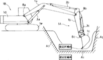
Fig. 2 is a kind of schematic diagram of using a setting regions shape around hydraulic excavating machine equipment of the present invention and this excavator of expression;
Fig. 3 is the schematic diagram that used zone in coordinate system method and the control of the first embodiment region limited excavation is set in expression;
Fig. 4 is the schematic diagram of an example of setting regions among expression first embodiment;
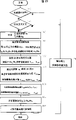
Fig. 5 is the control flow chart of steps of carrying out in control module of expression;
Fig. 6 is expression first embodiment a kind of diagram of adjusting the goal pace vector method in the deceleration area and the district that resets;
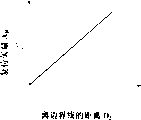
Fig. 7 is the curve that concerns the distance of expression from the bucket front end to the setting regions boundary line and the time constant;
Fig. 8 represents distance from the bucket front end to the setting regions boundary line and the curve that reduces to concern the factor;
Fig. 9 is the flow chart that the expression lever signal reduces to control details;
Figure 10 is the diagram that an expression changes by the input of low-pass filtering treatment control stick;
Figure 11 is the curve of representing the distance from the bucket front end to the setting regions boundary line and reducing to concern the vector factor;
Figure 12 be illustrated in direction change control down the bucket front end move along the diagram of the example in path;
Figure 13 is the curve that concerns the distance of expression from the bucket front end to the setting regions boundary line and the reset vector;
Figure 14 be illustrated in reset control down the bucket front end move along the diagram of the example in path;
Figure 15 be expression second embodiment of the invention construction Machines the region limited excavation system with and the diagram of fluid power system;
Figure 16 is the schematic diagram of expression hydraulic operation type control lever unit details;
Figure 17 is the functional-block diagram of expression control module control function;
Figure 18 is the schematic diagram of expression compensating for tilt angle method;
Figure 19 is the flow chart of the control step details partly carried out of expression control stick deceleration control;
Figure 20 is the diagram that concerns between the infusion rate of expression guiding pressure and flow control valve;
Figure 21 is that the expression direction changes the treatment step flow chart that control section is carried out;
Figure 22 is that distance Y a and the direction of expression from the bucket front end to the setting regions boundary line changes the curve that concerns the factor h the control section;
Figure 23 is that the expression direction changes another treatment step flow chart that control section is carried out;
Figure 24 is the curve of expression apart from relation between the Fa and function Vcyf=f (Ya);
Figure 25 is the treatment step flow chart that the expression reset control part is carried out;
Figure 26 be expression third embodiment of the invention construction Machines the region limited excavation system with and the diagram of fluid power system;
Figure 27 is the functional-block diagram of expression control module control function;
Figure 28 is illustrated in after bucket front end speed limit value is determined, the curve that concerns distance from the bucket front end to the setting regions boundary line and the bucket front end speed limit value that adopted;
Figure 29 is that expression bucket front end is in the setting district, when situation on the boundary line of setting district and the setting district outside, by other diagram of operating space of cantilever adjustment bucket front end speed;
Figure 30 is that the expression lever signal reduces to control the treatment step flow chart that calculating section is carried out;
Figure 31 is that the expression lever signal reduces to control the treatment step flow chart that conversion portion is carried out.
The following several embodiments of the present invention that are used for hydraulic crawler excavator of describing with reference to each accompanying drawing.
At first with reference to Fig. 1 to 10 explanation first embodiment of the present invention;
Among Fig. 1, use hydraulic crawler excavator of the present invention and comprise: hydraulic pump 2; A plurality of hydraulic gears of the hydraulic fluid of origin self-hydraulic pump 2, they comprise cantilever tank 3a, boom cylinder 3b, bucket cylinder 3c, turning motor 3d and left and right sides orbit motor 3e, 3f; The a plurality of control levers unit 14a-14f that is set up corresponding to hydraulic gear 3a-3f respectively; Be connected a plurality of flow control valve door 15a-15f between hydraulic pump 2 and a plurality of hydraulic gear 3a-3f, described each flow control valve door is subjected to the control from the corresponding operating signal Sa-Sf of control lever unit 14a-14f, delivers to the corresponding flow velocity of the hydraulic fluid of hydraulic gear 3a-3f with control; And a reducing valve 6, when the pressure between hydraulic pump 2 and the flow control valve door 15a-15f surpasses predetermined value, open it.Said modules is formed fluid power system jointly, is used for driving the driven unit of hydraulic crawler excavator.Control lever unit 14a-14f in the present embodiment is electric level type, and the output signal of telecommunication is as operation signal Sa-Sf.The opposed end of flow control valve door 15a-15f has electric power-hydraulic pressure conversion equipment, as comprise solenoid-activated part 30a, 30b-35a, the 35b of proportion magnetic valve, and, handle solenoid-activated part 30a, 30b-35a, the 35b that the relevant signal of telecommunication Sa-Sf of the direction of control lever unit 14a-14f is sent to flow control valve door 15a-15f with the size of input and operator along it.
As shown in Figure 2, hydraulic crawler excavator is made up of a more piece anterior device 1A and a main body 1B, described anterior device comprises cantilever 1a, suspension rod 1b and bucket 1c, they each can both pivotally rotate by in the vertical direction, described main body comprises superstructure 1d and underframe 1e.The cantilever 1a of anterior device 1A is supported on the front portion of described superstructure 1d at its cardinal extremity.Cantilever 1a, suspension rod 1b, bucket 1c, superstructure 1d and underframe 1e are with for being driven parts, and they are driven by cantilever tank 3a, boom cylinder 3b, bucket cylinder 3c, turning motor 3d and left and right sides orbit motor 3e, 3f respectively.These are driven the instruction works of parts according to control lever unit 14a-14f.
The region limited excavation control apparatus of present embodiment is provided in the hydraulic crawler excavator as above-mentioned structure.Described control system comprises: setting device 7, be used for providing instruction, and to set an excavation regions, the predetermined portions of described anterior device can be mobile in this zone by predetermined in advance operation procedure as the front end of bucket 1c; Operating type changeover switch 20 is used for selecting speed priority job mode or accuracy priority job mode; Angular transducer 8a, 8b, 8c are assemblied in the pivot place of cantilever 1a, suspension rod 1b and bucket 1c respectively, in order to along with the corner that detects them with respect to the state variation of the position of anterior device 1A and attitude; Control module 9A be used for receiving operation signal Sa-Sf from control lever unit 14a-14f, from the course of work of setting device 7 arrange signal, from the selection signal of operating type changeover switch 20, and from the detection signal of angular transducer 8a, 8b, 8c, the excavation regions that the front end of setting bucket 1c can move therein, and adjust operation signal Sa-Sf.
Operating type changeover switch 20 is such as the selector switch that selectively is switched on or switched off by the operator (changing its state of maintenance into after changing end).When operating type changeover switch 20 is disconnected, select speed priority job mode, and when it is connected, select accuracy priority job mode.
Control module 9A comprises that region setting part divides and the region limited excavation control section.Region setting part divides according to the instruction of setting device 7 carries out the calculating of setting the excavation regions that bucket 1c front end can move therein.Hereinafter with reference to Fig. 3 a kind of example of setting the excavation regions method is described.Be noted that and in vertical plane, set excavation regions in this example.
Among Fig. 3, handling according to the operator after anterior device moved to the front end of bucket 1C the position that P1 orders, the instruction of response setting device 7, calculate this front position of bucket 1C at this moment, make setting device 7 work subsequently, the degree of depth h1 of input from this position to excavation regions boundary line point P1* is so that set according to the degree of depth.Then, after the front end with bucket 1C moves to the position that P2 orders, according to top same method, the instruction of response setting device 7, calculate the front position of bucket 1C at this moment, and make setting device 7 work, the degree of depth h2 of input from this position to excavation regions boundary line point P2* is so that set according to the degree of depth thereupon.After this, extrapolate the formula that expression connects the straight line of 2 P1* and P2*, and this straight line is set at the boundary line of excavation regions.
There are the various sizes of anterior device 1A and main body 1B in its memory in control module 9A, region setting part divides according to the data of being deposited and corner α, β, 2 P1 of value calculating of γ and the position of P2 simultaneously, and described each corner is recorded by angular transducer 8a, 8b, 8c respectively.As an example, at this moment the position of 2 P1 and P2 is defined as pivoting point with cantilever 1a and is in the XY coordinate system of the origin of coordinates coordinate figure (X1, Y1), (X2, Y2).The XY coordinate system is the rectangular coordinate system that is fixed on the main body 1B, and hypothesis is in the perpendicular.Distance between the pivoting point of the pivoting point of given cantilever 1a and suspension rod 1b is L1.Distance between the pivoting point of the pivoting point of suspension rod 1b and bucket 1c is L2, and the distance between the pivoting point of bucket 1c and the bucket 1c front end is L3, then utilizes following formula, by corner α, β, γ determine in the XY coordinate system coordinate figure (X1, Y1), X2, Y2):
X=L1sinα+L2sin(α+β)+L3sin(α+β+γ)
Y=L1cosα+L2cos(α+β)+L3cos(α+β+γ)
Region setting part divides by just like following such 2 P1 on the boundary line, setting district that calculate
*And P2
*The Y coordinate figure, determine their coordinate figure:
Y1
*=Y1-h1
Y2
*=Y2-h2 obtains expression and connects 2 P1
*And P2
*The formula of straight line as follows:
Y=(Y2
*-Y1
*)X/(X2-X1)+
(X2Y1
*-X1Y2
*)/(X2-X1)
Then, an origin of coordinates is set on above-mentioned straight line, determine for example have the rectangular coordinate system of an axle by P2 by same straight line
*The XaYa coordinate system of the origin of coordinates that point is determined, and definite transform data that is tied to the XaYa coordinate system from the XY coordinate.
When utilizing independent straight line to set the boundary line of excavation regions in the last example, can in perpendicular, set excavation regions by the mutual combination of many straight lines with any required form.Fig. 4 represents an example of latter event, wherein utilizes three straight line A1, A2 and A3 to set described excavation regions.In this case, can set the boundary line of excavation regions by each bar straight line A1, A2 and A3 are carried out and above-mentioned same operation and calculating.
Region limited excavation control section among the control module 9A is carried out control according to the zone of setting by said process (following normal title setting district), so that limit movably zone of anterior device 1A according to flow process shown in Figure 5.Below in the process description region limited excavation control section control action of reference Fig. 5, carry out the description of the present embodiment course of work.
At first, at step 200 input operation signal Sa-Sf from control lever unit 14a-14f, and the cantilever 1a, the suspension rod 1b that record by angular transducer 8a, 8b, 8c in step 210 input and the corner of bucket 1c.
Then, in step 250, the various sizes of the anterior device 1A that is deposited in the memory according to the corner α, the β that record, γ and control module 9A are calculated anterior device 1A predetermined portions, as the position of bucket 1c front end.At this moment, divide performed program by region setting part above being similar to, calculate the front position of bucket 1c earlier as the value in the XY coordinate system.The transform data that utilizes region setting part to determine in dividing then becomes value in the XaYa coordinate system with the value transform in these XY coordinate systems.Thereby, finally calculate the value of front position in the XaYa coordinate system of bucket 1c.
Subsequently determine bucket 1c front end whether in deceleration area shown in Figure 6 in step 225, this deceleration area has been positioned at as the boundary line, setting district of above-mentioned setting and near this boundary line.If the front end of bucket 1c is in this deceleration area, then program enters step 257, determines whether operating type changeover switch 20 is also to connect or disconnection.If operating type changeover switch 20 is switched on, then program enters step 260, and if it is disconnected, then program enters step 270.
In step 260, control module is carried out the program (following normal title action bars signal reduces program) that reduces from the operation signal Sa-Sc of anterior device 1A control lever unit 14a-14c.
In step 270, at bucket 1c front end place, goal pace vector V c is subjected to indicate from control lever unit 14a-14c operation signal Sa-Sc, and the operation signal has here experienced the deceleration program in step 260.The memory of control module 9A is also stored from the operation signal Sa-Sc of control lever unit 14a-14c and by the correlation between the feed flow flow velocity of flow control valve door 15a-15c.By the respective value of determining to pass through flow control valve door 15a-15c feed flow flow velocity from the operation signal Sa-Sc of action bars unit 14a-14c, determine the expection actuating speed of hydraulic jack 3a-3c from these feed flow flow speed values, and calculate the goal pace vector V c at bucket front end place according to the various sizes of these expection actuating speeds and anterior device 1A.At this moment, be similar to the calculating of bucket front position in the step 250, by the value of first compute vectors Vc in the XY coordinate system, utilize region setting part to divide the transform data of determining that these value transforms are become XaYa coordinate system intermediate value again, calculate the value of goal pace vector V c in the XaYa coordinate system.Here, the Xa coordinate figure Vcx of goal pace vector V c in the XaYa coordinate system represents goal pace vector V c along the velocity component that is parallel to setting regions boundary line direction, and Ya coordinate figure Vcy represents goal pace vector V c along the velocity component perpendicular to setting regions boundary line direction.
Subsequently, in step 280, adjust goal pace vector V c, anterior device 1A is slowed down, after this, program enters step 290.
In addition, if the front end of determining bucket 1c when step 255 not at deceleration area, then calculates in step 270A after the goal pace vector V c at bucket 1c front end place of origin operation signal Sa-Sc instruction of controlled bar unit 14a-14c, program enters step 290.When step 270A, except making its experience deceleration program, origin operation signal Sa-Sc promptly is not used as the operation signal of control lever unit 14a-14c, and the calculating of goal pace vector V c is the same during with step 270.
After this, whether the front end of determining bucket 1c in step 290 is in outside, setting district shown in Figure 6, and this setting district is set as explained above.If the front end of bucket 1c is in this outside, setting district, then program enters step 300, at that time, adjusts goal pace vector V c, makes the front end of bucket 1c get back to this setting regions.If in this outside, setting district, then program does not enter step 310 to the front end of bucket 1c.
Subsequently, in step 310, calculate and operation signal Sa-Sc at the corresponding flow control valve door 15a-15c of step 280 or 300 resulting adjusted goal pace vector V c.This process is the inverse process of the calculating goal pace vector V c of execution in the step 260.
Then, in step 320, the operation signal Sa-Sf that control module output is imported when step 200, perhaps when step 310, calculate operation signal Sa-Sc, and the operation signal Sd-Sf of input when step 200 gets back to beginning then.
Determine the bucket front end when being described in step 255 hereinafter with reference to Fig. 7-12 whether in deceleration area, the operation signal Sa-Sc during step 260 slows down and handles, and is the adjustment of deceleration control to goal pace vector V c when step 280.
As the value that is used for setting the deceleration area scope, the memory stores of control module 9A distance Y a1 as shown in Figure 6 from the boundary line, setting district.In step 255, determine distance D 1 between bucket front position and the boundary line, setting district from the Ya coordinate figure of the determined bucket 1c of step 250 front position.Subsequently, if distance D 1, determines then that the bucket front end has entered deceleration area less than distance Y a1.
The memory of control module 9A is also stored distance D 1 from bucket 1c front end to the boundary line, setting district shown in Figure 7 and the correlation the time constant tg, and described distance D 1 shown in Figure 8 and lever signal reduce the correlation between the factor hg.Correlation between described distance D 1 and the time constant tg is set at, when described distance D 1 during greater than distance Y a1, time constant tg equals 0 (t2=0), and when described distance D 1 during less than distance Y a1, reduce with distance D 1, time constant tg increases, and when distance D 1=0, it gets maximum value (tg=tgmax).In addition, described distance D 1 and the correlation that reduces between the factor hg are set at, when in described distance D 1 during greater than distance Y a1, reduce factor hg and equal 1 (hg=1), and described distance D 1 along with distance D 1 reduces, reduces factor hg and reduces according to following formula during less than distance Y a1:
Hg=Csin (θ g) D1+hgmin and when D1=0, the C that it is got in minimum value (tg=tgmin (≠ the 0)) following formula is a constant, θ g is that (suspension rod 1b can pivotally rotate around it by the front end that connects bucket 1c and suspension rod pin, be the position of setting angle sensor 8b) the angle that become with respect to the excavation regions boundary line of straight line, as shown in Figure 3.In other words, θ g more hour reduces factor hg (from from farther position, excavation regions boundary line) in more earlier and begins to reduce.
As shown in Figure 9, in step 260, at first when step 261, the distance D of being determined by step 255 1 and the relations of Fig. 7 and 8 expressions are calculated the time constant tg of predetermined instant and are reduced factor hg.At this moment, as top said, because the function of the angle θ g that to reduce factor hg be the front end that connects bucket 1c forms with respect to the boundary line of excavation regions with the straight line of suspension rod 1b pivot center, so calculate earlier definite angle θ g when reducing factor hg.Various sizes by the anterior device 1A that deposited in the memory according to detected corner α, β, γ and control module 9A are calculated the front position of bucket 1c and the position of suspension rod 1b pivot center, and then from these positional values and join domain setting section determined 2 P1
*And P2
*The formula of straight line calculate angle θ g, thereby determine angle θ g.
Subsequently, in step 262, utilize time constant tg that operation signal Sa-Sc is carried out low-pass filtering treatment, thereby obtain the first operation signal Sa1-Sc1 that reduces.In step 263, take advantage of the first operation signal Sa1-Sc1 that reduces to reduce factor hg, obtain the second operation signal Sa2-Sc2 that reduces.
Here, the low-pass filtering treatment in carry out step 262 according to following design formulas:
Output=X
N-1+ (1-e
-aT) (X
n-X
N-1) X wherein
n: the operation signal of importing between sampling date in advance
X
N-1: in the output valve between sampling date in advance
a=1/tg
The time of an operating process of T=
In step 262, carry out low-pass filtering treatment and mean that the origin operation signal Sa-Sc with staircase waveform that is imported is adjusted to the first slower operation signal Sa1-Sc1 that reduces of rising about operation signal Sa-Sc, as shown in figure 10, and cause lever action is slowed down significantly.In addition, along with reducing of distance D 1, the used time constant tg of low-pass filtering treatment increases, and this means the border along with the more close excavating area of front end of bucket 1c, forces the first operation signal Sa1-Sc1 that reduces to rise slowlyer.Thereby along with the front end of bucket 1c is healed near the border of excavating area, an amount of minimizing degree that operation signal Sa-Sc rises strengthens gradually.
In addition, in step 263, take advantage of the first operation signal Sa1-Sc1 that reduces to mean to reduce factor hg, because reducing along with distance D 1, hg gets less value, so along with the more close border of getting the district of excavating of the front end of bucket 1c, the second operation signal Sa2-Sc2 that reduces is reduced.And in this case,, the reduction of operation signal Sa-Sc level is strengthened gradually along with the front end of bucket 1c is healed near the border of excavating area.In addition, just like above-mentioned, to be the front end that connects bucket 1c become the SIN function of angle θ g with the straight line of suspension rod 1b pivot center with respect to the boundary line, excavating area to hg, and under the less situation in θ g angle, it gets less value.So when anterior device 1A was reached position far away, the second operation signal Sa2-Sc2 that reduces diminished, and makes with bigger amount to reduce operation signal Sa-Sc.So, when under the situation of extending anterior device 1A far, operating, operation signal Sa-Sc is reduced with bigger amount, here in the said situation of extending far, the velocity of bucket 1c front end has the component of bigger edge towards the excavating area boundary direction, and the front end of anterior device may leave described excavation regions further.
The memory of control module 9A is also stored the distance D 1 from bucket 1c front end to the border, setting district shown in Figure 11 and is reduced correlation the vector factor h.Relation between distance D 1 and the factor h is set for, and during greater than distance Y a1, factor h equals 0 (h=0) in distance D 1, and during less than distance Y a1, along with reducing of D1, factor h increases gradually in distance D 1, and when distance D 1=0, factor h equals 1 (h=1).
When step 280, c is adjusted to the goal pace vector V, make at bucket 1c front end place along vector component towards excavation regions boundary direction goal pace vector V c, be that its vector component perpendicular to the excavation regions border reduces, in other words, the Ya coordinate figure Vcy in the calculated XaYa coordinate system of step 260 reduces.Specifically, calculate corresponding with definite distance D 1 in the step 255 vector factor h that reduces by depositing relation shown in Figure 11 in the memory of control module 9A.Make Ya coordinate figure (vertical vector component) Vcy of goal pace vector V c calculated the vector factor h that reduces take advantage of, and then taken advantage of by-1 again, obtain deceleration vector VR (=-h Vcy).Then VR is added on the Vcy.The deceleration vector VR here is a velocity, it and Vcy opposite orientation, and along with the distance D 1 from bucket 1c front end to the border, setting district reduces and increases gradually from Ya1, and afterwards when D1=0, it becomes and equals-Vcy (VR=-Vcy).Therefore, on the vertical vector component Vcy that deceleration vector VR is added to goal pace vector V c, this vertical vector component Vcy is reduced, along with distance D 1 reduces from Ya1, the amount that vertical vector component Vcy reduces strengthens gradually.Finally make goal pace vector V c be adjusted to goal pace vector V ca.
Figure 12 represents the example in a path, when above-mentioned adjusted goal pace vector V ca carries out deceleration control, this approach of front end edge of bucket 1c is moved.Specifically, given goal pace vector V c is to oblique below orientation and be constant, it is identical that its parallel component Vcx keeps, and its vertical component Vcy is along with the front end of bucket 1c reduces near the border of setting district (promptly along with distance D 1 from Ya) more) and reduce gradually.Because adjusted goal pace vector V ca is synthesizing of described parallel component and vertical component, so as shown in figure 12, the curved shape in described path, it is bent to when near the boundary line of setting district parallel with it gradually.In addition, because under the situation of D1=0, h=1, and VR=-Vcy are so adjusted goal pace vector V ca is consistent with parallel component Vcx on the boundary line of setting district.
Like this, in the deceleration control of step 280,,, bucket 1c front end finally is converted to along the direction on border, setting district so moving direction because bucket 1c front end is slowed down to moving of border, setting district.Consider this point, the deceleration control in the time of also can be with step 280 is called direction and changes control.
Describe with reference to Figure 13 and 14 below and be used for determining the bucket front end, and the goal pace vector V c when step 300 adjusts, in order to the control that resets outside the setting district whether in the step 290 of outside, setting district.
When step 290,, determine bucket front position outside the setting district and the distance D 2 between the boundary line, setting district by the Ya coordinate figure of determined bucket 1c front position in the step 250.If the value of distance D 2 is just changed to by negative, determine that then the bucket front end has shifted out the setting district.
The memory of control module 9A is also stored distance D 2 from bucket 1c front end to the border, setting district shown in Figure 13 and the correlation the reset vector AR.Relation between distance D 2 and the reset vector AR is set for, reset vector AR is increased gradually along with the increase of distance D 2.
When step 300, c is adjusted to the goal pace vector V, the goal pace vector V c of front end place of bucket 1c is become along the vertical component towards the boundary line, setting district along the vector component (it is calculated in step 260, i.e. Ya coordinate figure Vcy in the XaYa coordinate system) perpendicular to boundary line, setting district direction.Specifically, the inverse vector Acy of Vcy is added on the vertical vector component Vcy, offseting it, and isolates parallel vectors component Vcx.Adopt this adjustment, can prevent that the front end of bucket 1c from shifting out the setting district further.After this, calculate corresponding to the reset vector AR of distance D 2 between bucket 1c front end and the boundary line, setting district at this moment by relation shown in the Figure 13 that is deposited in the memory.With calculate reset vector AR be set at the vertical component Vcya of goal pace vector V c.Here, reset vector AR is a contrary velocity, and it reduces gradually along with the minimizing of distance D 2 between the front end of bucket 1c and the boundary line, setting district.Therefore, by reset vector AR being set at the vertical velocity component Vcy of goal pace vector V c, make goal pace vector V c be adjusted to goal pace vector V ca, its vertical vector component Vcya reduces gradually with the minimizing of distance D 2
Figure 14 represents that the example in a path when above-mentioned adjusted goal pace vector V ca resets control, moves this approach of front end edge of bucket 1c.Specifically, given goal pace vector V c is to oblique below orientation and be constant, it is identical that its parallel component Vcx keeps, and since reset vector AR be directly proportional with distance D 2, so its vertical component Vcy reduces gradually along with the border of the close more setting district of the front end of bucket 1c (promptly along with distance D 1 reduces from Ya1).Because adjusted goal pace vector V ca is synthesizing of described parallel component and vertical component, so as shown in figure 14, the curved shape in described path, it is bent to when near the boundary line of setting district parallel with it gradually.
Thus, in the control that resets of step 300, because the front end of control bucket 1c returns the setting district, so the area definition that will reset is in outside, described setting district.In addition, in the described control that resets, bucket 1c front end is slowed down towards moving of the boundary line of setting district, and bucket 1c front end move direction and finally is transformed into along the direction of boundary line, setting district.Consider this point, also the control that resets can be called direction and change control.
In the superincumbent scheme, control lever unit 14a-14f constitutes a plurality of manipulation devices, is used to instruct a plurality of parts that are driven, the i.e. action of cantilever 1a, suspension rod 1b, bucket 1c, superstructure 1d and underframe 1e.The functor that region setting part among setting device 7 and the control module 9A divides constitutes regional set mechanism, in order to set movably zone of anterior device.Angular transducer 8a-8c constitutes first checkout gear, is used to detect the state variation relevant with attitude with the position of anterior device 1A.Means 250 among Fig. 5 constitute first calculation element, are used for according to from position and attitude as the calculated signals anterior device 1A of the angular transducer 8a-8c that detects first checkout gear that the state variation relevant with attitude with the position of anterior device 1A use.In addition, suppose that suspension rod 1b is the first specific front assembly, and cantilever 1a is the second specific front assembly, then means 260 constitute the first signal guiding mechanism, when anterior device 1A is near the boundary line of setting district in the zone, according to first calculation element 250 calculate value, (in the operation signal Sa-Sc of present embodiment) is used for adjusting the operation signal Sb from control lever unit 14b relevant with the first specific front assembly 1b in the middle of a plurality of control levers unit 14a-14f at least.Means 270 and 280 constitute the secondary signal guiding mechanism, at least according to being subjected to the operation signal Sa2-Sc2 that the first signal guiding mechanism 260 reduces, and by first calculation element 250 calculate value, calculating is used for the speed Vc of anterior device 1A control, and according to this speed Vc that is used to control, (in the operation signal Sa-Sc of present embodiment) adjusts the operation signal Sa from control lever unit 14a relevant with the second specific front assembly 1a in the middle of a plurality of control levers unit 14a-14f at least, make that in described setting district anterior device is lowered along the translational speed towards the boundary line, setting district.
Have, the means 257 fabrication process mode selection mechanisms among operating type changeover switch 20 and Fig. 5 are in order to select whether adjust the operation signal Sa-Sc of control lever unit 14a-14f, so that made it to reduce by the first signal guiding mechanism again.When making operating type selection mechanism 20,257 be operated in selection not adjusted by the first signal guiding mechanism, the first signal guiding mechanism 260 is not adjusted operation signal Sa-Sc, simultaneously secondary signal guiding mechanism 270,280 at least according to the operation signal Sa-Sc that is adjusted and first calculation element 250 calculate value calculate the speed Vc that is used for anterior device 1A control, and adjust (the operation signal Sa-Sc's of present embodiment) operation signal Sa at least from the control lever unit 14a relevant with the second specific front assembly 1a according to the speed Vc that this is used for controlling.
Employing has this embodiment as constituted above, when bucket 1c front end leaves the border of setting district, does not adjust goal pace vector V c in step 270A, and can fulfil assignment by normal mode.When bucket 1c front end in the speed district comparatively when the border, in step 280, adjust goal pace vector V c, make along being reduced towards the vector component of boundary line, the setting district direction vector component of boundary line (promptly perpendicular to).So the bucket front end edge is slowed down perpendicular to mobile being controlled of boundary line, setting district direction, but is not reduced along the velocity component of boundary line, setting district direction, bucket 1c front end can be moved by picture as shown in Figure 12 along the boundary line of setting district.Thereby, can under the situation that limits bucket 1c front end moving area, excavate effectively.
When selecting accuracy priority job mode by operating type changeover switch 20, make from the operation signal Sa-Sc of control lever unit 14a-14f and be subjected to low-pass filtering treatment and lever signal reduces to handle in step 260, by these, operation signal Sa-Sc itself is reduced with the front position of bucket 1c and the distance between the boundary line, setting district.So, in step 280, have as described above, make and handle resulting operation signal Sa2-Sc2 by these and be adjusted.When selecting speed priority job mode by operating type changeover switch 20, have as described above, the operation signal Sa-Sc from control lever unit 14a-14f is adjusted, and is not reduced.So, under any circumstance, all can in step 280, carry out deceleration control (direction changes control).
Because control realizes that direction changes control as speed in step 280, so if the speed of anterior device 1A is very big, if control lever unit 14b is handled suddenly, then because the response lag in the control procedure, as the delay in the underground, and the reasons such as inertia force of anterior device 1A, may make anterior device 1A leave the zone that sets to a great extent.
In the present embodiment,, select accuracy priority job mode, in step 280, utilize in step 260 to change control through the operation signal Sa2-Sc2 travel direction that low-pass filtering treatment and lever signal reduce to handle by connecting operating type changeover switch 20.Therefore, along with the front end of bucket 1c near the border, setting district, even very big, too fast the moving of anterior device 1A is suppressed from the operation signal of control lever unit 14a-14f.In addition,, also allow hydraulic gear 3a-3c not only to begin reposefully to move, and Once you begin move, also obtain a slower speed even control lever unit 14a-14f is handled suddenly.This has alleviated response lag in the control procedure, as the influence that postpones in the underground, and the influence of inertia.So, can reduce anterior device 1A during the deceleration control in step 280 and reach amount outside the setting district, and can be along the mobile exactly anterior device 1A in the boundary line of setting district.
Therebetween, when in step 280, adopting the operation signal Sa2-Sc2 travel direction that reduces to handle through low-pass filtering treatment and lever signal in step 260 to change control, even when the operator wants mobile quickly anterior device 1A, because the fast moving of anterior device 1A is suppressed, operating efficiency is descended.In the present embodiment, when connecting operating type changeover switch 20, when selecting accuracy priority job mode, anterior device 1A is moved, but reduced anterior device 1A and reached amount outside the setting district, and when disconnecting operating type changeover switch 20, during selection speed priority job mode, owing to utilize operation signal Sa-Sc to realize that direction changes control in step 280, so anterior device 1A is moved according to the size of operation signal Sa-Sc, and not reducing operating efficiency, described operation signal Sa-Sc is actual in control lever unit 14a-14c.
Therefore, adopt this embodiment, when in the localized area, excavating, the operator can comply with its wish, conversion operating type changeover switch 20, by the operation of preferred operating type, the front end that such mode can be selected from bucket 1c reaches the less accuracy priority job mode of amount outside the setting district, also or can make the speed priority job mode of anterior device 1A fast moving.
Have again, adopt present embodiment, if the direction in step 280 changes control period, the front end of bucket 1c reaches outside the setting district to a certain degree, goal pace vector V c is adjusted, cause the front end of bucket 1c to return the setting district, thereby the bucket front end is controlled, after it has reached outside the setting district, be moved back into the setting district rapidly.Thereby can carry out excavation in the localized area more exactly.
In addition, adopt present embodiment, when the front end of bucket 1c is controlled, when making it retract the setting district, goal pace vector V c is adjusted to along the vector component towards boundary line, setting district direction along the vector component perpendicular to boundary line, setting district direction, does not reduce and do not make at the velocity component along boundary line, setting district direction.Therefore, the front end that can also make bucket 1c moves on to the outside, setting district reposefully along the boundary line of setting district.Thus, owing to be adjusted along vector component towards boundary line, setting district direction, become along with the front end of bucket 1c and the distance D 2 between the boundary line, setting district reduce and become littler, thereby, at the control period that resets, the bucket front end becomes curve shape according to adjusted goal pace vector V ca along its path of moving, as shown in figure 14, it is bent to when near the boundary line of setting district parallel with it gradually.So, can be that mode makes the front end of bucket retract the setting district stably to heal.
With reference to Figure 15 to 25 second embodiment of the present invention is described below.Among these figure, represent with identical reference number with the parts of equivalence among Fig. 1.
With reference to Figure 15, the fluid power system that is provided on the hydraulic press of realizing present embodiment comprises a plurality of control lever unit 4a-4f that are set up corresponding to transmission mechanism 3a-3f respectively, also comprise a plurality of a plurality of flow control valve door 5a-5f that are connected between hydraulic pump 2 and a plurality of hydraulic gear 3a-3f, also each is controlled according to the corresponding operating signal from control lever unit 4a-4f these flow control valve doors, delivers to the corresponding flow velocity of the hydraulic fluid of hydraulic gear 3a-3f in order to control.
Each control lever unit 4a-4f is a hydraulic pressure guiding type, utilizes one of flow control valve door 5a-5f of guiding pressure-driven correspondence.As shown in figure 16, each control lever unit 4a-4f comprises a control lever 40 and a pair of reducing valve 41,42 handled by the operator, in order to produce guiding pressure according to amount and direction by described control stick 40 inputs of manipulation.Reducing valve 41,42 is linked the main entrance and exit of pump 43, and the secondary access is then by guiding pipeline 44a, 44b; 45a, 45b; 46a, 46b; 47a, 47b; 48a, 48b; 49a, 49b link corresponding flow control valve door hydraulic drive part 50a, 50b; 51a, 51b; 52a, 52b; 53a, 53b; 54a, 54b; 55a; One of 55b.
A region limited excavation control apparatus that is equipped on just like the present embodiment in the hydraulic crawler excavator of said structure also comprises: setting device 7, operating type changeover switch 20 and angular transducer 8a, 8b, 8c.Also comprise: slant angle sensor 8d is used for detecting the tilt angle theta of main body 1B on fore-and-aft direction; Proportion magnetic valve 10a links to each other with master control pump 43 in the main entrance and exit side, is used for reducing guiding pressure from master control pump 43 according to adding thereon the signal of telecommunication, and the guiding pressure that is lowered of output; Reversal valve 12 links to each other with the guiding pipeline 44a of the control lever unit 4a of cantilever and the secondary discrepancy oral-lateral of proportion magnetic valve 10a, be used for selecting guiding one higher in the guiding pressure of pipeline 44a and the controlled pressure that proportion magnetic valve 10a is provided, and selected pressure is introduced the hydraulic drive part 50a of flow control valve 5a, proportion magnetic valve 10b, 10c, 10d is installed among the guiding pipeline 44b of control lever unit 4a of cantilever respectively and the guiding pipeline 45a of the control lever unit 4b of suspension rod, among the 45b, be used for reducing the guiding pressure of corresponding guiding pipeline, and export the guiding pressure that is lowered according to the corresponding electric signal that adds thereon; Pressure sensor 60a, 60b; 61a, 61b are installed in guiding pipeline 44a, 44b; The main entrance and exit side of people's oral-lateral of reversal valve 12 and proportion magnetic valve 10b, 11a, 11b among 45a, the 45b, in order to detect the corresponding guiding pressure as input quantity, control lever unit 4a, 4b are handled by this pressure just; Pressure sensor 61c, 61d are installed in the secondary discrepancy oral-lateral of proportion magnetic valve 11a, 11b among guiding pipeline 45a, the 45b, in order to detect the corresponding guiding pressure that is added to hydraulic drive part 51a, the 51b of flow control valve door 5b by proportion magnetic valve 11a, 11b; And control module 9, its receive from the course of work of setting device 7 arrange signal, from the selection signal of operating type changeover switch 20, from the detection signal of angular transducer 8a, 8b, 8c and slant angle sensor 8d, and from pressure sensor 60a, 60b; 61a, 61b; The detection signal of 61c, 61d, and the signal of telecommunication exported to proportion magnetic valve 10a-11b.
The control function of control module 9 is shown among Figure 17.Control module 9 comprises various functions, they change control section 9e, later stage by regional set-up and calculated part 9a, anterior Attitude Calculation part 9b, expection oil cylinder speed calculating section 9c, expection front end velocity calculating section 9d, direction adjusts expection oil cylinder speed calculating section 9f, reset control part 9g, later stage and adjusts expection oil cylinder speed calculating section 9h, expection oil cylinder velocity selector 9i, expection guiding calculation of pressure part 9j, valve command calculations part 9k, and lever signal reduces processing section 9m and carries out.
Zone set-up and calculated part 9a carries out the excavation regions set-up and calculated according to the instruction of setting device 7, and described zone is the movable zone of bucket 1c front end.Setting the mode of excavation regions divides the mode of carrying out the same with above-mentioned with reference to region setting part among first embodiment of Fig. 3 description.So, determine to be tied to the transform data of XaYa coordinate system, wherein the initial point of XaYa coordinate system and coordinate axes all on the boundary line of setting district (referring to Fig. 3) from the XY coordinate.
When main body 1B is tilted as shown in Figure 18, the relative position relation between bucket front end and the ground is changed, just can not correctly carry out the setting of excavation regions.Therefore, in the present embodiment, utilize the tiltangle of slant angle sensor 8d detection main body 1B, and the detected value of tiltangle is imported anterior Attitude Calculation part 9b, it calculates the bucket front position in the XbYb coordinate system, and described XbYb coordinate system turns over the θ angle by the XY coordinate system and provides.Like this, even main body 1B is tilted, also can correctly set excavation regions.What should illustrate is, even main body tilts, but begins after the inclination of having proofreaied and correct main body under the situation of operation, perhaps under the situation about excavating in the operation place that main body will can not tilt, always do not need slant angle sensor.
Anterior Attitude Calculation part 9b is according to the various sizes of anterior device 1A in the memory that is had control device 9 and main body 1B, and the corner α, the β that are recorded by angular transducer 8a, 8b, 8c respectively, γ calculate the position of anterior device 1A predetermined portions, as the value in the XY coordinate system.
Reduce among the control section 9m at lever signal, whether the front end of determining bucket 1c is as shown in Figure 6 in deceleration area, and this district is positioned at the border, setting district set by regional set-up and calculated part 9a or near this boundary line.If the front end of bucket 1c is in this deceleration area, then when selecting accuracy priority job mode by operating type changeover switch 20, carry out lever signal and reduce to handle, to reduce operation signal (guiding pressure) from the control lever unit 14b of anterior device 1A suspension rod.
Figure 19 is that the expression lever signal reduces operating procedure flow chart performed among the control section 9m.At first, when step 150, determine whether the front end of bucket 1c has entered deceleration area.As the value that is used for setting the deceleration area scope, the memory stores of the control module 9 distance Y a1 that leaves the border, setting district as shown in Figure 6.Specifically, when step 150, the transform data that utilization obtains in regional set-up and calculated part 9a, bucket 1c front position in the XY coordinate system that will be determined by anterior Attitude Calculation part 9b is transformed into the value in the XaYa coordinate system, and, determine the front position of bucket 1c in the setting district and the distance D 1 between the boundary line, setting district by the Ya coordinate figure of bucket front position.So, if distance D 1, determines then that the front end of bucket has entered deceleration area less than distance Y a1.Entered deceleration area if determine the front end of bucket in step 150, then program enters step 152, determines that operating type changeover switch 20 is switched on actually, still is disconnected.If operating type changeover switch 20 is switched on, then program enters step 160.
In step 160, computing time constant tg and reduce factor hg.The same among this calculating of tg and hg and first embodiment, therefore will no longer describe below.
Program enters step 161 then.Providing the guiding pressure as the suspension rod operation signal that is recorded by pressure sensor 61a, 61b is Pa, Pb, in step 161, utilizes evaluation time constant tg that guiding pressure Pa, Pb are carried out low-pass filtering treatment, is Pa1, Pb1 with the guiding pressure that draws through adjusting.This calculating in the low-pass filtering treatment also with first embodiment in the same, therefore following will not the description.
Then, when step 162, determine, and calculate speed VAC1, the VAD1 of boom cylinder 3b from determined flow velocity by feed flow flow velocity corresponding to the flow control valve door 5b of the guiding pressure Pa 1 through adjusting, Pb1.The memory of control module 9 also stores as shown in figure 20 guiding pressure P BU, PBD, PAC, PAD and by the correlation between feed flow flow velocity VB, the VA of flow control valve door 5a, 5b.Utilize the relation of these storages, control module is determined the feed flow flow velocity by flow control valve door 5b, and calculates speed VAC1, the VAD1 of boom cylinder in step 162.What should illustrate is can result calculated to be existed in the memory of control module 9 by calculating the relation between guiding pressure and the oil cylinder speed in advance, directly from guiding the speed that pressure is determined described oil cylinder again.
Then, in step 163, determine the oil cylinder speed minimum value VADmin (maximum value of absolute value) under oil cylinder speed maximum value VACmax and the unloading situation thereof that dumps under the situation of boom cylinder 3b from relation shown in Figure 20.Take advantage of this maximum value VACmax and minimum value VADmin with reducing factor hg then, obtain the maximum value VAC2 through adjusting and the minimum value VAD2 of corresponding oil cylinder speed through adjusting.
Subsequent when step 164, minimum value between VAC1 and the VAC2 is set for expection oil cylinder speed VAC under the unloading situation of boom cylinder 3b, and the maximum value between VAD1 and the VAD2 (minimum value between VAD1 and the VAD2 absolute value) is set for the expection oil cylinder speed VAD under the situation that dumps of boom cylinder 3b.So, under the situation of VAC1>VAC2 and VAD1<VAD2, select VAC2 and VAD2, thus will expect the maximum value of oil cylinder speed and minimum value VAC, VAD be defined as respectively through adjusting maximum value VAC2 and through the minimum value VAD2 of adjustment.
In step 165, guide pressure Pa 2, Pb2 after this from the expection that expection oil cylinder speed VAC, VAD calculate guiding pipeline 45a, the 45b.This process is the inverse process that boom cylinder speed performed in the step 162 is calculated.
After this, from step 165, calculate expection guiding pressure Pa 2, Pb2, in step 166, be calculated as and obtain the required proportion magnetic valve 11a of these expection guiding pressure, the operating value of 11b.
On the other hand, if distance D 1 is greater than distance Y a1, and the front position of determining bucket 1c when step 150 is not in deceleration area, if perhaps operating type changeover switch 20 is determined to be disconnected when step 152, then program enters step 170, and output makes proportion magnetic valve 11a, 11b open maximum valve operation value.
Here, just as first embodiment, carry out low-pass filtering treatment and mean at step 161 pair guiding pressure Pa, Pb, the be step-like initial guiding pressure Pa, Pb of input are adjusted to rising slower guiding pressure Pa 1, Pb1 through adjusting, as shown in figure 10, the result is that the operation of lever is slowed down significantly.Also have,, strengthen the time constant tg that uses in the low-pass filtering treatment and mean,, force guiding pressure Pa 1, Pb1 to rise slowlyer through adjusting along with the front end of bucket 1c is healed near the boundary line of excavating area along with reducing of distance D 1.Thereby along with the front end of bucket 1c is healed near the boundary line of excavating area, the amount that guiding pressure Pa 1, the size of Pb1 reduce strengthens gradually.
In addition, in step 163, to reduce maximum value VACmax and the minimum value VADmin that factor hg takes advantage of oil cylinder speed, obtain the maximum value VAC2 through adjusting and the minimum value VAD2 of oil cylinder speed through adjusting, this means owing to the hg that reduces along with distance D 1 gets less value, so the maximum value VAC2 through adjusting, and the absolute value of the minimum value VAD2 through adjusting all reduces along with the boundary line of the close excavating area of healing along with the front end of bucket 1c.In addition, the SIN function of the hg angle θ g that to be the front end that connects bucket 1c form with respect to the boundary line of excavation regions with the straight line of suspension rod 1b pivot center, and locate at less θ g angle, hg gets less value.Therefore, when anterior device 1A reaches position far away, the maximum value VAC2 through adjusting, and the absolute value of the minimum value VAD2 through adjusting all reduces.So when VAC2, VAD2 being elected to be expection oil cylinder speed VAC, VAD in step 164, along with the front end along with bucket 1c is more stretched far near the boundary line and the anterior device 1A of excavating area, expection guiding pressure Pa 2, Pb2 reduce bigger amount.
Expection oil cylinder speed calculating section 9c receives the guiding force value that is recorded by pressure sensor 60a, 60b, 61c, 61d, determine to pass through the feed flow flow velocity of flow control valve door 5a, 5b from above-mentioned relation shown in Figure 20, and calculate the goal pace of cantilever tank 3a and boom cylinder 3b from determined feed flow flow velocity.
The expection oil cylinder speed that the bucket front position that expection front end velocity calculating section 9d determines from anterior Attitude Calculation part 9b, expection oil cylinder speed calculating section 9c determine, and the various sizes of being deposited in the memory of control module 9, determine the goal pace vector V c of bucket 1c front end as L1, L2 and L3.At this moment, at first goal pace vector V c is defined as the value in the XY coordinate system as shown in Figure 3, and then utilize in advance by what regional set-up and calculated part 9a determined and be tied to the transform data of XaYa coordinate system from the XY coordinate, by the value transform in the XY coordinate system being become the value in the XaYa coordinate system, be defined as the value in the XaYa coordinate system.Here, the Xa coordinate figure Vcx of goal pace vector V c in the XaYa coordinate system represents that an edge is parallel to the vector component of boundary line, setting district direction, and its Ya coordinate figure Vcy represents the vector component of an edge perpendicular to boundary line, setting district direction.
When bucket 1c front end is positioned at setting regions near its border, and goal pace vector V c has along towards the component of boundary line, setting district the time, direction changes control section 9e and adjusts this velocity component, makes it along with being reduced gradually along with the boundary line of the close excavating area of healing along with the bucket front end.In other words, make one to be added on the vector component Vcy less than vertically velocity component Vcy and the vector component (inverse vector) that directionally leaves this speed district.
Figure 21 is that the expression direction changes performed control flow chart of steps among the control section 9e.At first determine the component of goal pace vector V c perpendicular to the boundary line, setting district in step 100, promptly the Ya coordinate in the XaYa coordinate system is positive or negative.If Ya coordinate figure Vcy is positive, this means that the bucket front end has the setting vector that the border, setting district is left in sensing.So program enters step 101, here Xa coordinate figure Vcx and the Ya coordinate figure Vcy with goal pace vector V c is set at adjusted vector component Vcxa, Vcya.If Ya coordinate figure Vcy bears, this means that the bucket front end has the setting vector of sensing towards the border, setting district.So, program enters step 102, for travel direction changes control, here the Xa coordinate figure Vcx with goal pace vector V c is set at adjusted vector component Vcxa, and will be set at adjusted vector component Vcya by the value of taking advantage of Ya coordinate figure Vcy gained with factor h.
Such just as shown in Figure 22, here, as the distance Y a between bucket 1c front end and the border, setting district during greater than predetermined value Ya1, the value of factor h gets 1, and as described distance Y a during less than predetermined value Ya1, a reduces along with distance Y, the value of factor h reduces gradually from 1, and when described distance Y a became 0, promptly when the bucket front end arrived the border of setting district, the value of factor h got 0.This relation between h and Ya is existed in the memory of control module 9.
Change among the control section 9e in direction, utilize in advance by regional set-up and calculated part 9a is determined and be tied to the transform data of XaYa coordinate system from the XY coordinate, the bucket 1c front position that calculating section 9b is determined is transformed into the value in the XaYa coordinate system.Then, determine distance Y a between bucket 1c front end and the border, setting district, and, determine factor h by distance Y a according to the relation of Figure 22 by the Ya coordinate figure.
By the vertical vector component Vcy that adjusts goal pace vector V c is as described above arranged, this vertical vector component Vcy is reduced, so that along with the reducing of described distance Y a, the amount that this vertical vector component Vcy is reduced strengthen.So, make goal pace vector V c be adjusted to goal pace vector V ca.
When changing control by above-mentioned adjusted goal pace vector V ca travel direction, it is the same with top first embodiment that describes with reference to Figure 12 that bucket 1c front end moves the path on institute edge.
Figure 23 is the flow chart that the expression direction changes the another example of control step performed among the control section 9e.In this example, if determine that in step 100 goal pace vector V c is negative perpendicular to the component Vcy (being the Ya coordinate figure of goal pace vector V c) on border, setting district, then program enters step 102A, here, functional relation Vcyf=f that deposited, shown in Figure 24 (Ya) determines corresponding to Ya coordinate figure Vcyf distance Y a between bucket 1c front end and the border, setting district, that reduced in the memory by control module 9, then, with among Ya coordinate figure Vcyf and the Vcy less one be set at adjusted vector component Vcya.This provides a kind of progress, promptly when the front end of mobile bucket 1c slowly, even the bucket front end comparatively near the border of setting district, makes the speed of bucket reduce never again, and can be along with each operation execution of operator.
Although the vertical component of bucket front end goal pace vector as above be reduced said, but because the caused error of manufacturing difference of flow control valve door and other hydraulic test, be difficult to accomplish often make the bucket front end run out of the setting district in the vertical velocity component in vertical distance Ya=0 place zero (0).Yet, in the present embodiment, owing to reduce control just like the top said lever signal that carried out, but also realized the control that resets that the back will be addressed, so almost the bucket front-end control can be carried out operation on the boundary line of setting regions.Because uniting the implementation lever signal, employing reduces the control and the control that resets, so, just the relation shown in Figure 10 and 13 can be set at, make factor h and reduce later Ya coordinate figure Vchf slightly to become zero above-mentioned (0) at vertical distance Ya=0 place.
On the other hand, in above-mentioned control, keep the horizontal component (Xa coordinate figure) of goal pace vector identical, but always do not need to make horizontal component to keep identical.Described horizontal component may increase so that bucket front end speed raises, and described horizontal component is reduced, so that bucket front end speed reduces.
Later stage is adjusted expection oil cylinder speed calculating section 9f and changes the expection oil cylinder speed that the determined adjustment of control section 9e back goal pace vector calculates cantilever tank 3a by direction.This process is the inverse process of performed calculating among the expection front end velocity calculating section 9d.
At this, tightening up suspension rod to described main body, under the situation of carrying out digging operation (promptly tightening up the suspension rod operation), owing to can reduce because of lifting of cantilever 1a makes the vertical component Vcy of goal pace vector V c, described calculating section 9f calculates the expection oil cylinder speed of the cantilever 1a that moves up.In addition, by the joint operation (i.e. Lian He suspension rod unloading operation) that cantilever descends and suspension rod unloads, operating along the direction that pushes away bucket under the situation of bucket front end, when when carrying out this suspension rod unloading operation near the position (proximal most position) of main body, be given in the expection vector that leaves on the direction of setting district.In this case, owing to can the vertical component Vcy of goal pace vector V c be reduced by the cantilever operation is converted to the cantilever rise from cantilever decline, be converted to the expection oil cylinder speed of cantilever rise so described calculating section 9f calculates in order to the cantilever operation is descended from cantilever.
When the bucket front end leaves the setting district, in reset control part 9g, adjust the goal pace vector according to the distance of leaving the boundary line, setting district, so that the bucket front end returns the setting district.In other words, the oil cylinder oil cylinder is added on the vector component Vcy greater than vertically vector component Vcy and the orientation vector (inverse vector) towards the setting district.
Figure 25 is the flow chart of the performed control step of expression reset control part 9g.At first whether the front end of determining bucket 1c in step 110 and the distance Y a between the boundary line, setting district be for just also or for bearing.Here, from the transform data that the XY coordinate is tied to the XaYa coordinate system value that the determined front position of front end Attitude Calculation part 9b is transformed into the XaYa coordinate system is determined distance Y a by utilization, and then as described above, try to achieve the Ya coordinate figure that is converted.If distance Y a is for just, the front end that just means bucket is still in the setting district.So program enters step 111, at that time, each all is set at 0 with the Xa coordinate figure Vcx of goal pace vector V c and Ya coordinate figure Vcy, changes control to realize the said direction of above-mentioned priority.If distance Y a means then that for negative the bucket front end has shifted out the setting district.So, program enters step 112, at that time, for the control that resets, the Xa coordinate figure Vcx of goal pace vector V c is set at adjusted vector component Vcxa, and will be set at adjusted vector component Vcya by the value of taking advantage of the distance Y a gained between bucket front end and the boundary line, setting district with factor-K.Here, factor K is the suitable value of determining from the viewpoint of control characteristic, and-K Vcy represents one along backward velocity, it reduces along with distance Y a and diminishes.Therefore, K can be a function, and a reduces along with distance Y, and its value reduces gradually.In this case, a reduces along with distance Y, and-K Vcy reduces by bigger rate of change.
By adjusting the vertical vector component Vcy of goal pace vector V c as described above, make goal pace vector V c be adjusted to goal pace vector V ca, thereby a reduce along with distance Y, make vertical vector component Vcy reduce.
When resetting control by above-mentioned adjusted goal pace vector V ca, it is the same with top first embodiment that describes with reference to Figure 14 that bucket 1c front end moves the path on institute edge.So, return setting regions owing to bucket 1c front end is controlled by reset control part 9g, so, make the zone that resets be limited at the outside of described setting district.
Later stage is adjusted expection cantilever tank speed calculating section 9h from the determined expection oil cylinder speed of adjusting back goal pace vector calculating cantilever tank 3a of reset control part 9g.This process is the inverse process of the performed calculating of expection front end velocity calculating section 9d.In the control that resets, described calculating section 9h calculates the expection oil cylinder speed of the cantilever 1a that moves up, uses so that the bucket front end returns the setting district along with lifting on the cantilever 1a.
Expect that oil cylinder velocity selector 9i changes the expection oil cylinder velocity amplitude of control and bigger (maximum value) of expection cantilever tank velocity amplitude selection that is used to reset and controls that described expection cantilever tank speed calculating section 9h determines from the definite direction that is used for of described expection cantilever tank speed calculating section 9f, and then selected value is set at the expection cantilever tank speed that will export.
Here, the distance Y a between bucket front end and boundary line, setting district is timing, in the step 111 of Figure 25 the goal pace vector component is set at 0, and the goal pace vector component that sets in the step 101 or 102 of Figure 21 always has bigger value.Therefore, select to change the expection cantilever tank speed of controlling by the direction that is used for that described expection cantilever tank speed calculating section 9f determines.When described distance Y a for the vertical component Vcy of negative and goal pace vector also when negative, in the step 102 of Figure 21, adjusted vertical component Vcya is set at 0, since h=0, and the vertical component that sets in the step 112 of Figure 25 always has bigger value.Therefore, select by the reset expection cantilever tank velocity amplitude of control of described expection cantilever tank speed calculating section 9h being used to of determining.When described distance Y a is timing for the vertical component Vcy that bears the goal pace vector, the expection oil cylinder velocity amplitude that selection is determined by described expection cantilever tank speed calculating section 9f or 9h, in view of the above, among the vertical component KYa in the step 112 of the goal pace vector V c that sets in the step 101 of Figure 21 and Figure 25 has bigger value.Along band ground,,, selector 9i can be arranged to and get two kinds of component sums such as except selecting maximum value as a kind of selection.
Expection guiding calculation of pressure part 9j is by the guiding pressure among expection oil cylinder speed calculating pipeline 44a, the 44b that will export, expected oil cylinder velocity selector 9i selection.In a process is the inverse process of calculating performed among the expection oil cylinder speed calculating section 9c.
Valve command calculations part 9k from expection guiding calculation of pressure part 9j calculate expection guiding calculation of pressure proportion magnetic valve 10a, the required command value of 10b, in order to increase these expection guiding pressure.By amplifier these command value are amplified, and export to proportion magnetic valve 10a, 10b as the signal of telecommunication.
When realizing that direction changes control (deceleration control), as top said, tightening up under the situation of suspension rod operation, cantilever is lifted, and under cantilever rising situation,, realize that cantilever lifts by the signal of telecommunication being exported to the proportion magnetic valve 10a relevant with pipeline 44a.Be positioned at than it perpendicular to the state on ground more under the suspension rod unloading situation near the suspension rod position teamwork of main body, the action that makes cantilever is fallen from cantilever and is transformed into cantilever and lifts, and discharge boom moves to slow down.By making the signal of telecommunication of exporting to the proportion magnetic valve 10b that is arranged in guiding pipeline 44b under falling situation at cantilever is zero, and signal of telecommunication of Comparative Examples electromagnetic valve 10a output, realizes thisly being lowered to the conversion that cantilever lifts from cantilever.In the control that resets, under cantilever lifts situation, a signal of telecommunication is exported to and guided pipeline 44a relevant proportion magnetic valve 10a.When another kind of situation, will export to proportion magnetic valve 10b with the corresponding signal of telecommunication of guiding pressure, to produce described guiding pressure from control lever unit 4a.
In the superincumbent layout, when anterior device 1A in setting regions during near its boundary line, suppose that suspension rod 1b is the first specific front assembly, cantilever 1a is the second specific front assembly, lever signal reduces control section 9m and proportion magnetic valve 11a, 11b constitute the first signal guiding mechanism, be used for according to the anterior Attitude Calculation part 9b as first calculation element calculate value, at least adjust and operation signal Pa or Pb, to reduce operation signal Pa or Pb from the relevant control lever unit 4b of the first specific front assembly 1b of a plurality of control levers unit 4a-4f centre.Expection oil cylinder speed calculating section 9c, expection front end velocity calculating section 9d, direction changes control section 9e, later stage is adjusted expection oil cylinder speed calculating section 9f, expection oil cylinder velocity selector 9i, expection guiding calculation of pressure part 9j, valve command calculations part 9k, proportion magnetic valve 10a, 10b and reversal valve 12 constitute the secondary signal guiding mechanism, be used at least according to the operation signal Pa2 that has been reduced by the first signal guiding mechanism 260 or Pb2 (in the present embodiment for Pa2 or Pb2 and from the operation signal of control lever unit 4a) and by first calculation element calculate value calculate the speed Vc that control anterior device 1A uses, and adjust at least according to the speed Vc that is used for controlling that (present embodiment is control lever unit 4a with operation signal from the relevant control lever unit 4a of the second specific front assembly 1a in the middle of a plurality of control levers unit 4a-4f, the operation signal of 4b), make anterior device in the setting district, be reduced along translational speed towards the boundary line, setting district.
In addition, the means 152 fabrication process mode selection mechanisms among operating type changeover switch 20 and Figure 19 are used for selecting the operation signal Pa of control lever unit 4b or Pb whether to be subjected to the adjustment of the first signal guiding mechanism and are reduced.When operation mode changeover switch 20,152 work in selection when not adjusted by the first signal guiding mechanism, the first signal guiding mechanism 9m, 11a, 11b does not adjust operation signal Pa or Pb, while secondary signal guiding mechanism 9c, 9d, 9e etc. at least according to the operation signal Pa that adjusted or Pb (in the present embodiment for Pa or Pb and control lever unit 4a operation signal) and the first calculation element 9b calculate value calculate and be used for the speed Vc that anterior device 1A controls, and (present embodiment is control lever unit 4a to adjust the operation signal of the control lever unit 4a relevant with the second specific front assembly 1a at least according to this speed Vc that is used for controlling, the operation signal of 4b).
The working condition that below description is had the present embodiment of above-mentioned layout, following description will be carried out as above-mentioned same job instances, the situation that also is the purpose of excavated earth and tightens up suspension rod (promptly tighten up suspension rod operation) to main body, and by cantilever fall and the teamwork of suspension rod unloading along the situation (promptly unloading load combined operation) of the direction direction operation bucket front end that pushes away with suspension rod.
When for the purpose of excavated earth when main body is tightened up suspension rod, the front end of bucket 1c moves closer to the boundary line of setting district.If the distance between bucket front end and the boundary line, setting district becomes less than Ya1, then direction change control section 9a adjusts, to reduce the goal pace vector V c of bucket front end place along vector component (being the vector component in vertical edges boundary line) towards boundary line, setting district direction, thereby realize the direction of bucket front end is changed control (deceleration control), specifically, later stage is adjusted expection cantilever tank speed calculating section 9f and calculates the speed of oil cylinder along cantilever tank 3a dimension, expection guiding calculation of pressure part 9j calculates cantilever and lifts the expection guiding pressure among the guiding pipeline 44a under the situation, and valve command calculations part 9k is to the proportion magnetic valve 10a output signal of telecommunication.Therefore, proportion magnetic valve 10a output and calculating section 9j calculate expection guiding pressure control corresponding pressure, reversal valve 12 is selected these controlled pressures, and guides the hydraulic drive part 50a of cantilever cantilever flow control valve door 5a when lifting into.Along with the action like this of proportion magnetic valve 10a, the bucket front end edge is controlled perpendicular to the mobile of setting district boundary direction, slowly lowers, and does not reduce but do not make along the velocity component of setting district boundary direction.Therefore, can as shown in Figure 12 the border, front end edge setting district of bucket 1c be moved.Like this, just can when qualification bucket 1c front end is movably regional, excavate effectively.
Even narrate as top, when the front end of bucket 1c is subjected to deceleration control during near the boundary line in the setting district, if moving of anterior device 1A is very fast, if control lever unit 4b is handled, because the response lag in the control procedure, and the inertia of anterior device 1A, the front end of bucket 1c may leave setting regions to a certain extent.In the present embodiment, at this moment,, select accuracy priority job mode, make to reduce to reduce among the 9m of processing section to add to the flow control valve door 5b hydraulic drive part 51a of suspension rod, the guiding pressure of 51b at lever signal by connecting operating type changeover switch 20.So, even the translational speed of anterior device 1A is very big, along with the front end of bucket 1c near the border, setting district, also can make too fast mobile being suppressed of anterior device 1A.In addition, even control lever unit 4b is handled, also can make boom cylinder 3b begin reposefully to move.But after beginning to move, also get slower speed.This has suppressed the influence that lags behind in the hydraulic circuit, and the influence of inertia like this, during deceleration control, can reduce the degree that anterior device 1A protrudes into the setting regions outside.And can move anterior device 1A along the boundary line of setting district exactly.
In addition, by disconnecting operating type changeover switch 20, selection speed priority job mode, reduce processing section 9m output in order to opening the valve command value of proportion magnetic valve 11a, 11b the biglyyest from lever signal, and the guiding pressure of control lever unit 4b is added to hydraulic drive part 51a, the 51b of the flow control valve door 5b of suspension rod.So, anterior device 1A is moved according to the size of guiding pressure, can not reduce operating efficiency.
Make it along the direction that pushes away the bucket front end to move by the action of falling associating with cantilever under the situation of suspension rod unloading simultaneously, when from when carrying out the suspension rod unloading operation, providing along the expection vector that leaves the setting district direction near the position (nearest position) of main body.In addition, in this case, if the distance between bucket front end and the boundary line, setting district becomes less than Ya1, for the direction change control (deceleration control) of bucket front end, direction changes control section 9e and carries out the adjustment of goal pace vector V c.Specifically, later stage is adjusted the oil cylinder speed of expection cantilever tank speed calculating section 9f calculating along cantilever tank 3a dimension, expection guiding calculation of pressure part 9j calculates cantilever and lifts the expection guiding pressure among the guiding pipeline 44a under the situation, and make the expection guiding pressure of falling under the situation among the guiding pipeline 44b at cantilever is zero, and valve command calculations part 9k is to the proportion magnetic valve 10a output signal of telecommunication, and the output of cut-out Comparative Examples electromagnetic valve 10b.So proportion magnetic valve 10b makes the guiding pressure among the guiding pipeline 44b be reduced to zero (0), proportion magnetic valve 10a output simultaneously will produce as the guiding pressure among the guiding pipeline 44a with expection guiding pressure control corresponding pressure, this pressure.Because this action of proportion magnetic valve 10a, 10b, change control according to tightening up the same mode travel direction of the situation of operation with top suspension rod.Therefore, can make bucket 1c front end, can excavate effectively, limit movably scope of bucket 1c front end along border, setting district fast moving.
If, select accuracy priority job mode, then make to reduce to reduce among the 9m of processing section to add to the flow control valve door 5b hydraulic drive part 51a of suspension rod, the guiding pressure of 51b at lever signal by connecting operating type changeover switch 20.Therefore,, then can not only make boom cylinder 3b begin reposefully to move, and after beginning to move, also get slower speed if control lever unit 4b is handled.This has suppressed the influence that lags behind in the hydraulic circuit and the influence of inertia.Like this, during deceleration control, can reduce the degree that anterior device 1A protrudes into the setting regions outside, and can move anterior device 1A along the boundary line of setting district exactly.
In addition, by disconnecting operating type changeover switch 20, selection speed priority job mode, reduce processing section 9m output in order to open the valve command value of proportion magnetic valve 11a, 11b the biglyyest from lever signal, and the guiding pressure of control lever unit 4b is added to hydraulic drive part 51a, the 51b of the flow control valve door 5b of suspension rod, anterior device 1A is moved according to the size of guiding pressure, and can not reduce operating efficiency.
As mentioned above, in the required hydraulic crawler excavator of the control system of band hydraulic operation type control lever unit, present embodiment also can provide with first embodiment in same progress.
Referring now to Figure 26 to 31 third embodiment of the present invention is described.Be denoted by like references those equivalent parts among Fig. 1 to 15 among these figure.
With reference to Figure 26, in the present embodiment in the hydraulic crawler excavator of being understood required fluid power system with the same shown in Figure 15.The present embodiment region limited excavation control apparatus that is comprised in such fluid power system is except establishing pressure sensor 60a, the 60b shown in Figure 15, and control module 9B has outside the following control function, with identical shown in Figure 15.
The control function of control module 9B is shown among Figure 27.Control module 9B comprises various functions, they are by regional set-up and calculated part 9a, anterior Attitude Calculation part 9b, bucket front end speed limit value calculating section 9C, boom cylinder speed calculating section 9D, the suspension rod bucket front end speed calculating section 9E that is correlated with, the cantilever bucket front end speed limit value calculating section 9F that is correlated with, cantilever tank speed limit value calculating section 9G, oil cylinder guiding pressure limit value calculating section 9H, oil cylinder related valve command calculations part 9I, lever signal reduces to control calculating section 9M, lever signal reduces to control conversion portion 9S, and suspension rod related valve command calculations part 9K carries out.
Identical among the processing capacity of zone set-up and calculated part 9a and anterior device Attitude Calculation part 9b and second embodiment shown in Figure 17.
Bucket front end speed limit value calculating section 9C calculates the limiting value of bucket front end speed perpendicular to the component of boundary line, setting district L according to the distance D of bucket front end to boundary line L.Utilize the relation as shown in figure 28 of being deposited in advance in the memory of control module 9B and read the relation of being deposited and carry out this calculating.
Transverse axis among Figure 28 is represented the distance D of bucket front end to boundary line L, and the longitudinal axis is represented the limiting value a of bucket front end speed perpendicular to boundary line L component.As the XaYa coordinate system, distance D on the transverse axis and the speed limit value a on the longitudinal axis are along be defined as just (+) in setting regions outside setting regions.Relation between distance D and limiting value a is set at: when the bucket front end is in setting regions, speed provides the component of bucket front end speed perpendicular to boundary line L along negative (-) direction with being directly proportional with distance D, and when the bucket front end was outside setting regions, speed edge just (+) direction provided the component of bucket front end speed perpendicular to boundary line L with being directly proportional with distance D.Therefore, in setting regions, have only when bucket front end speed perpendicular to the component of boundary line L greater than along the limiting value of negative (-) direction the time, the bucket front end is slowly fallen, and outside setting regions, then the edge just (+) direction make bucket front end speedup.
Boom cylinder speed calculating section 9D calculates the boom cylinder speed that is used to control according to the flow speed characteristic of command value (guiding pressure) and flow control valve 5b, and described command value is detected by pressure sensor 61c, 61d, is added to the flow control valve 5b of suspension rod.
Position and the state of the anterior device 1A that the relevant bucket front end speed calculating section 9E of suspension rod determines according to boom cylinder speed and anterior Attitude Calculation part 9b calculate relevant bucket front end speed (velocity) b of suspension rod.
The transform data that the relevant bucket front end speed limit value calculating section 9F of cantilever utilizes regional set-up and calculated part 9a to determine, with the relevant bucket front end speed b of suspension rod that determined by calculating section 9E from the XY coordinate system transformation to the XaYa coordinate system, calculate the relevant bucket front end speed (bx, by) of suspension rod, the bucket front end speed of also determining according to calculating section 9c is perpendicular to the relevant bucket front end with suspension rod of the limiting value a speed of the boundary line L component by perpendicular to boundary line L then, calculates the cantilever limiting value c of bucket front end speed perpendicular to boundary line L that be correlated with.Referring now to Figure 29 this process is described.
In Figure 29, the bucket front end speed that bucket front end speed limit value calculating section 9c determines provides the limiting value c of the relevant bucket front end speed of cantilever perpendicular to boundary line L perpendicular to the definite bucket front end speed b of the relevant bucket front end with suspension rod of the limiting value a speed calculating section 9E of boundary line L component perpendicular to poor (a-by) between the L component by of boundary line.Then, the relevant bucket front end speed limit value calculating section 9F of cantilever is by formula c=a-by calculating limit value c.
Following situation is respectively described the implication of limiting value c, i.e. situation, bucket front end situation and bucket front end the situation setting regions outside on setting regions boundary line of bucket front end in setting regions.
When the bucket front end is in setting regions, with bucket front end speed to be limited in the limiting value a of bucket front end speed to the proportional mode of the distance D of boundary line L perpendicular to boundary line L component with the bucket front end, and, so the relevant bucket front end speed of cantilever perpendicular to the component of boundary line L be constrained to c (=a-by).If bucket front end speed b greater than c, then slows to c with it perpendicular to boundary line L component.
When the bucket front end is on the L of setting regions boundary line, bucket front end speed is set at 0 perpendicular to the limiting value a of boundary line L component, and by the correct operation that cantilever is lifted when the speed c, the suspension rod of payment towards the setting regions outside bucket front end speed b that is correlated with.So bucket front end speed becomes 0 perpendicular to the component by of boundary line L.
When the bucket front end is outside setting regions, with bucket front end speed perpendicular to the component of boundary line L to be restricted to upward velocity a to the proportional mode of the distance D of boundary line L with the bucket front end.For this reason, always the cantilever that carries out under speed c lifts correct operation, and the bucket front end is got back in the setting district.
Cantilever tank speed limit value calculating section 9G is according to the limiting value c of the relevant bucket front end speed vertical edges boundary line L of cantilever, and position and the attitude of anterior device 1A, calculates cantilever tank speed limit value by the coordinate transform that utilizes aforementioned transform data.
Cantilever guiding pressure limit value calculating section 9H determines by calculating section 9G oil cylinder guiding that determine, relevant with cantilever tank speed limit pressure limit value according to the flow speed characteristic of the flow control valve door 5a of cantilever.
Cantilever related valve command calculations part 9I receives the guiding pressure limit value from calculating section 9H.When this limiting value is timing, calculating section 9I lifts situation according to cantilever, Comparative Examples electromagnetic valve 10a exports the voltage corresponding to this limiting value, thereby the guiding pressure limit that makes flow control valve door 5a hydraulic drive part 50a is in this limiting value, simultaneously fall situation, one zero (0) voltage of Comparative Examples electromagnetic valve 10b output according to cantilever.When this limiting value when negative, calculating section 9I falls situation according to cantilever, Comparative Examples electromagnetic valve 10b exports the voltage corresponding to this limiting value, thereby the guiding pressure limit that makes flow control valve door 5a hydraulic drive part 50b is in this limiting value, simultaneously lift situation, one zero (0) voltage of Comparative Examples electromagnetic valve 10a output according to cantilever.
Lever signal reduces to control calculating section 9M executable operations bar signal and reduces program, with the operation signal (guiding pressure) of the control lever unit 4b that reduces anterior device 1A suspension rod.
Figure 30 is the flow chart that the expression lever signal reduces to control the treatment step of carrying out among the calculating section 9M.At first in step 155, utilize the transform data that obtains among the regional set-up and calculated part 9a, to become the value in the XaYa coordinate system by the evolution of bucket 1c front end in the XY coordinate system that anterior Attitude Calculation part 9b determines, and determine the distance D between bucket 1c front position and border, setting district in the setting district by the Ya coordinate figure that the bucket front position obtains.After this, similarly handle, calculate the expection guiding pressure Pa 2, the Pb2 that intend being reduced for lever signal reduces to control among guiding pipeline 45a, the 45b by carrying out with step 160-165 shown in Figure 19.
Lever signal reduce to control conversion portion 9S selectively export by calculating section 9M according to bucket 1c front end whether in deceleration area, perhaps according to operating type selector switch 20 also whether connect or open calculate value.The details of this transfer process is shown among Figure 31.
Referring to Figure 31, in step 180, at first determine operating type selector switch 20 whether be depressed (being switched on).If be depressed, then program enters step 181, in step 181, determines whether bucket 1c front end enters in the deceleration area.As the value of setting the deceleration area scope, the memory stores of control module 9B has the distance Y a1 that leaves the boundary line, setting district as shown in Figure 8.Specifically, in step 181, determine then that less than distance Y a1 bucket 1c front end enters in the deceleration area if reduce to control calculating section 9M determined distance D in step 155 by lever signal.If determine that in step 181 bucket 1c front end has entered in the deceleration area, then program enters step 182, export there by calculating section 9M calculate value.If distance D is a negative value, then when D=0, continue to calculate expection guiding pressure as the limiting value output of suspension rod guiding pressure.On the other hand, if operating type selector switch 20 be not depressed (being disconnected) in step 180, if perhaps distance D is greater than distance Y a1, and determine that in step 181 bucket 1c front end is not in deceleration area, then program enters step 183, export a maximum value, as the limiting value of suspension rod guiding pressure.
Suspension rod related valve command calculations part 9K receives the limiting value from the suspension rod guiding pressure of conversion portion 9S.When this limiting value is timing, calculating section 9K exports a limiting value correspondent voltage therewith to the proportion magnetic valve 11a that tightens up situation at suspension rod, thereby the guiding pressure limit that makes flow control valve door 5b hydraulic drive part 51a is in this limiting value, simultaneously also to one zero (0) voltage of proportion magnetic valve 11b output in suspension rod unloading situation.When this limiting value when negative, calculating section 9K exports a limiting value correspondent voltage therewith to the proportion magnetic valve 11b in suspension rod unloading situation, thereby the guiding pressure limit that makes flow control valve door 5b hydraulic drive part 51b is also exported one zero (0) voltage to the proportion magnetic valve 11a that tightens up situation at suspension rod simultaneously in this limiting value.
In the superincumbent layout, suppose that suspension rod 1b is the first specific front assembly, and cantilever 1a is the second specific front assembly, the action bars signal reduces to control calculating section 9M and proportion magnetic valve 11a, 11b constitute the first signal guiding mechanism, be used for when anterior device 1A in the setting district when the boundary line, according to the anterior Attitude Calculation part 9b as first calculation element calculate value, at least adjust the operation signal of a plurality of control levers unit 4a-4f centre control lever unit 4b relevant, to reduce operation signal with the first specific front assembly.Bucket front end speed limit value calculating section 9C, boom cylinder speed calculating section 9D, the relevant bucket front end speed calculating section 9E of suspension rod, cantilever relevant bucket front end speed limit value calculating section 9F, cantilever tank speed limit value calculating section 9G, cantilever guiding pressure limit value calculating section 9H, cantilever related valve command calculations part 9I.Proportion magnetic valve door 10a and reversal valve 12 constitute the secondary signal guiding mechanism, in order at least according to the operation signal that has been reduced because of the first signal guiding mechanism and by first calculation element calculate value be calculated as the used speed b of control anterior device 1A, and control operation signal at least from control lever unit 4a relevant with the second specific front assembly 1a in the middle of a plurality of control levers unit 4a-4f according to this control rate b, so that the anterior device edge is reduced towards the translational speed of setting district boundary direction.
Whether in addition, operating type selector switch 20 and action bars signal reduce to control the selection mechanism of conversion portion 9S fabrication process mode, be used to select to make the operation signal of control lever unit 4b to be subjected to the adjustment of the first signal guiding mechanism and be reduced.When selecting not to be subjected to the first signal guiding mechanism to adjust when operation mode selection mechanism 20,9S work, the first signal guiding mechanism 9M, 11a, 11b do not adjust described operation signal, secondary signal guiding mechanism 9c, 9d, 9e etc. at least according to the operation signal adjusted and by the first calculation element 9b calculate value calculate the speed b that control anterior device 1A uses, and adjust the operation signal of the control lever unit 4a relevant at least according to this speed b with the second specific front assembly 1a.
Below description is had the working condition of the present embodiment of said structure.To narrate about several job instances below, promptly make the lower situation of cantilever (being that cantilever is fallen operation) and tighten up the situation (being that suspension rod tightens up operation) that the control lever unit 4b of directional control suspension rod tightens up suspension rod along suspension rod to be purpose towards the main body excavated earth with the location bucket front end control lever unit 4a that to be purpose fall the directional control cantilever along cantilever.
When being purpose with location bucket front end, when cantilever is fallen the control stick of control lever unit 4a of directional control cantilever, on behalf of the guiding pressure of control lever unit 4a command value, 44b will add to the hydraulic drive part 50b that falls the dirty speed control system valve of situation 5a at cantilever by the guiding pipeline.Meanwhile, calculating section 9C calculates the limiting value a (<0) of the bucket front end speed that is directly proportional to the distance D of boundary line, setting district L with the bucket front end according to relation shown in Figure 28, calculating section 9F calculates the limiting value c=a (<0) of the relevant bucket front end speed of cantilever, and oil cylinder guiding pressure limit value calculating section 9H calculates and the negative accordingly oil cylinder guiding of limiting value c pressure limit value, valve command calculations part 9I Comparative Examples electromagnetic valve 10b exports one and described limiting value correspondent voltage simultaneously, thereby be limited in the guiding pressure that cantilever is fallen the hydraulic drive part 50b of the dirty speed control system valve of situation 5a, also one zero (0) voltage of Comparative Examples electromagnetic valve 10a output becomes zero so that lift the guiding pressure of the hydraulic drive part 50a of the dirty speed control system valve of situation 5a at cantilever.Here, when bucket front end during away from boundary line, setting district L, by the absolute value of the cantilever of calculating section 9H gained guiding pressure limit value greater than guiding pressure, so proportion magnetic valve 10b output is from the guiding pressure of controlling bar unit 4a input from control lever unit 4a input.Therefore, cantilever is moved down gradually according to this guiding pressure from control lever unit 4a input.
Cantilever is moved down gradually along with having as described above, and the boundary line L of the close further setting district of bucket front end, make the limiting value c=a (<0) of the relevant bucket front end speed of cantilever calculated by calculating section 9F increase (its absolute value | a| or | c| reduces), and the absolute value of the corresponding cantilever instruction limiting value of being calculated by calculating section 9H (<0) is reduced.So, when the absolute value of described limiting value becomes less than the command value of control lever unit 4a, when the voltage of exporting to proportion magnetic valve 10b from valve command calculations part 9I is correspondingly reduced simultaneously, proportion magnetic valve 10b reduces and exports guiding pressure from control lever unit 4a input, adds to the guiding pressure of falling the hydraulic drive part 50b of the dirty speed control system valve of situation 5a at cantilever so that little by little limit according to limiting value c.Like this, along with the boundary line L of bucket front end near the setting district, the speed that cantilever is fallen is restricted gradually, and when the bucket front end arrives at the boundary line L of setting district, cantilever is stopped.The result just can locate the bucket front end easily and reposefully.
When the bucket front end escape to the boundary line L outside of setting district, by the relation of calculating section 9C according to Figure 28, the absolute value a of the bucket front end speed that will be directly proportional to the distance D of boundary line, setting district L with the bucket front end (=c) as on the occasion of calculating, export to one of proportion magnetic valve 10a and limiting value c correspondent voltage from valve command calculations part 9I simultaneously, add to the hydraulic drive part 50a that lifts the dirty speed control system valve of situation 5a at cantilever in order to guide pressure accordingly with limiting value a with one.Thereby make cantilever with the proportional speed of distance D under the direction lifted along cantilever move so that reset, afterwards, when the bucket front end is got back to the boundary line L of setting district, cantilever is stopped towards the setting district.The result can make the bucket front end be positioned more reposefully.
In addition, being purpose towards the main body excavated earth, the control lever unit 4b that tightens up the directional control suspension rod along suspension rod makes under the situation that suspension rod tightens up, to add to the hydraulic drive part 51a that tightens up the dirty speed control system valve of situation 5b at suspension rod from the guiding pressure of proportion magnetic valve 11a output (back have state), cause that suspension rod moves down towards main body.
Meanwhile, detect the guiding pressure (being the output pressure of proportion magnetic valve 11a) of the hydraulic drive part 51a that adds to flow control valve door 5b by pressure sensor 61c, and exporting to the calculating section 9D that calculates boom cylinder speed, calculating section 9E calculates the relevant bucket front end speed b of suspension rod subsequently.In addition, calculating section 9C calculates the limiting value a (<0) of the bucket front end speed that is directly proportional to the distance D of boundary line, setting district L with the bucket front end according to the relation of Figure 28, the be correlated with limiting value c=a-by of bucket front end speed of the cantilever of calculating section 9F calculating simultaneously.Here, when the bucket front end as satisfy concern a<by (| a|>| during away from the boundary line L of setting district, come computations value c by|) as negative value.So, valve command calculations part 9I exports to one of proportion magnetic valve 10b and described limiting value correspondent voltage, become this limiting value so that cantilever is fallen the guiding pressure limit of the hydraulic drive part 50b of the dirty speed control system valve of situation 5a, also Comparative Examples electromagnetic valve 10a exports one zero (0) voltage simultaneously, becomes zero so that cantilever lifts the guiding pressure of the hydraulic drive part 50a of the dirty speed control system valve of situation 5a.At this moment, owing to do not make control lever unit 4a action, therefore, do not guide the hydraulic drive part 50b that pressure is added to flow control valve door 5a.As a result, suspension rod is shifted to main body gradually according to the guiding pressure that adds to the hydraulic drive part 51a of flow control valve door 5b.
Along with suspension rod is shifted to main body gradually, and such bucket front end as described above is further near boundary line, setting district L, makes the bucket front end speed limit value a that is calculated by calculating section 9C increase (absolute value | a| reduces).So, when limiting value a become greater than calculate by calculating section 9E the relevant bucket front end speed b of suspension rod during perpendicular to the component by of boundary line L, as limiting value c=a-by on the occasion of the bucket front end speed of being correlated with by calculating section 9F calculating cantilever, valve command calculations part 9I exports one and limiting value c correspondent voltage to the proportion magnetic valve 10a that cantilever lifts under the situation simultaneously, in order that the guiding pressure limit of the hydraulic drive part 50a of flow control valve door 5a is become this limiting value, and cantilever fallen one zero (0) voltage of proportion magnetic valve 10b output under the situation, so that the guiding pressure of the hydraulic drive part 50b of flow control valve door 5a becomes zero.Therefore, carry out cantilever and lift operation, to adjust bucket front end speed, make bucket front end speed perpendicular to the component of boundary line L be restricted gradually to the proportional mode of the distance D of boundary line L from front end.So, utilize the relevant bucket front end speed of suspension rod to be parallel to the velocity component of not adjusting component bx and adjusting of boundary line L perpendicular to boundary line L according to limiting value c, realize that in same mode shown in Figure 12 deceleration direction changes control, can excavate along boundary line, setting district L simultaneously.
In addition, when the bucket front end has been moved out to outside the boundary line L of setting district, by calculating section 9C according to the relation shown in Figure 28, as limiting value a on the occasion of calculating and the proportional bucket front end of distance D speed from front end to boundary line, setting district L, the limiting value c=a-by (>0) of the relevant bucket front end speed of being calculated by calculating section 9F of cantilever is to increase with the proportional mode of limiting value a, and, make by valve command calculations part 9I and export to the voltage increase that cantilever lifts the proportion magnetic valve 10a under the situation according to limiting value c.Therefore, leave at the bucket front end under the situation of setting district, carry out the operation that cantilever lifts, in order to adjusting bucket front end speed so that the bucket front end with the proportional speed of distance D under reset to the setting district.Thereby, with with same mode shown in Figure 14 under, make the bucket front end return boundary line, setting district L gradually, and when moving along it, be parallel to not adjusting under component bx and the associating of adjusting according to limiting value c of boundary line L in the relevant bucket front end speed of suspension rod, excavate perpendicular to the velocity component of boundary line L.Therefore, by tightening up suspension rod, can excavate reposefully along boundary line, setting district L.
In addition, superincumbent suspension rod tightens up in the operation, detect the guiding pressure of representing suspension rod control lever unit 4b command value by pressure sensor 61a, and the detection signal of pressure sensor 61a is added to the action bars signal reduce to control calculating section 9M, this calculating section calculates and is used for the expection guiding pressure that the action bars signal reduces to control.In this case, when the bucket front end when satisfying the boundary line L concern D 〉=Ya1 away from the setting district, perhaps when operation mode selector switch 20 is disconnected, limiting value as suspension rod guiding pressure, the action bars signal reduces to control maximum value of conversion portion 9S output, rather than the expection of being calculated by calculating section 9M guiding pressure, simultaneously, valve command calculations part 9K exports a correspondent voltage to the proportion magnetic valve 11a that suspension rod tightens up under the situation, in order to open proportion magnetic valve 11a to greatest extent.Therefore, the guiding pressure by control lever unit 4b input is added to the hydraulic drive part 51b that suspension rod tightens up the dirty speed control system valve of situation 5b.As a result, along with each operation of control lever unit 4b, the operator moves down suspension rod towards main body.
When not only shifting to main body bucket front end and concern that according to satisfying D<Ya1 is like that near the boundary line L of setting district along with suspension rod, but also when operating type selector switch 20 is switched on, limiting value as suspension rod guiding pressure, the action bars signal reduces to control the expection guiding pressure that conversion portion 9S output is calculated by calculating section 9M, be used for lever signal and reduce control, and valve command calculations part 9K exports one and described limiting value correspondent voltage to the proportion magnetic valve 11a that suspension rod tightens up under the situation, in order that the guiding pressure limit of flow control valve door 5b hydraulic drive part 51a is become described limiting value.Therefore, along with the boundary line L of the more close setting district of bucket suspension rod is slowed down.
As seeing from top narration, present embodiment also can provide with first and second embodiment similarly progressive.
In above each embodiment, utilize the low-pass filtering treatment process of time constant tg, and take advantage of the moderating process of operation signal all to reduce to be carried out in the control at lever signal with reducing factor hg.But also can only carry out to reduce the moderating process that factor hg takes advantage of operation signal.
Having, in above each embodiment, is the predetermined portions of the bucket front end being elected as anterior device again.But,, a pin of suspension rod front portion can be elected as predetermined parts of anterior device from realizing viewpoint of the present invention in comparatively simple mode.In addition, when for the interference that prevents anterior device and guarantee that purpose of safety sets one when regional, the predetermined portions of anterior device can be the other parts of this interference of any participation.
Described as the center closed system that comprises the case type flow control valve 15a-15f in center though will use fluid power system of the present invention, the present invention also can be applied to comprise the central opening system of central opening type flow control valve.
Distance between bucket front end and boundary line, setting district is not limited to the correlation that sets among above each embodiment with respect to deceleration vector, time constant tg, the correlation that reduces factor hg and reset vector, but can set by variety of way.
More than each embodiment be constructed such that when proper bucket front end leaves the border of setting district, in fact export the goal pace vector.Even but under such condition, can also be adjusted for any other purpose makes the goal pace vector.
Though with the goal pace vector along towards the vector component of boundary line, setting district direction as describing perpendicular to the boundary line, setting district, also can be in the vertical direction difference, as long as the bucket front end is being moved on the direction of boundary line, setting district.
Among superincumbent second embodiment etc., wherein the present invention is applied to the hydraulic crawler excavator with hydraulic operation type control lever unit, and proportion magnetic valve 10a, 10b, 11a, 11b are used as electric power-hydraulic pressure conversion equipment and decompressor.But also can replace these proportion magnetic valves with any other suitable electric power-hydraulic pressure conversion equipment.
In addition, though control lever unit 14a-14f and flow control valve 15a-15f have been described as the hydraulic operation type, only needing at least control lever unit 14a, 14b and flow control valve 15a, 15b for cantilever and suspension rod is getting final product of hydraulic operation type.
According to the present invention, owing to when forwardly installing border near the setting district, anterior device is slowed down, towards the mobile of border, setting district so can in a limited zone, excavate effectively.
In addition, because the operation signal of operating mechanism itself is reduced, so, also can in a limited zone, excavate reposefully even when operating mechanism is operated suddenly.
Also have, when excavating in a limited zone, the operator can select a kind of in accuracy priority job mode and the speed priority job mode by its wish.
Claims (10)
1. the region limited excavation control apparatus of a construction Machines, it comprises: a plurality of driven parts (1a-1e), they comprise a plurality of front assemblies (1a-1c), constitute the anterior device (1A) of a more piece, and the in the vertical direction pivotable; A plurality of hydraulic gears (3a-3f) drive a plurality of described driven parts respectively; A plurality of controlling organization (14a-14f; 4a-4f), be used for commanding described a plurality of action that is driven parts; And it is a plurality of according to from the driven hydraulic control valve of the actuating signal of described a plurality of operating mechanisms (15a-15f; 5a-5f), be used for controlling the flow velocity of the hydraulic fluid of delivering to described a plurality of hydraulic gears, it is characterized in that, described control system also comprises:
Zone set mechanism (7; 7,9a), be used for setting the movable range of described anterior device (1A);
First checkout gear (8a-8d) is used for detecting position and the relevant state variation of attitude with described anterior device (1A);
First calculation element (250; 9b), be used for position and attitude according to the described anterior device of the calculated signals of described first checkout gear (1A);
The first signal guiding mechanism (260; 9m, 11a, 11b; 9M, 11a, 11b), when described anterior device (1A) in the setting district during near its boundary line, be used for according to described first calculation element calculate value be adjusted at a plurality of controlling organization (14a-14f at least; The controlling organization relevant with the first specific front assembly (1b) 4a-4f) (14b, operation signal 4b) is to reduce this operation signal;
Secondary signal guiding mechanism (270,280; 9c-9f, 10a, 10b, 12,9D-9I, 10a, 10b, 12), at least according to the operation signal that reduces by the described first signal guiding mechanism and by described first calculation element calculate value in order to calculate the speed (Vc of the described anterior device of control (1A); B), and according to the described speed that is used for controlling be adjusted at described a plurality of operating mechanism and the relevant controlling organization (14a of the second specific front assembly (1a) at least; Operation signal 4a) so that described anterior device in the setting district along translational speed (Vcy towards setting regions boundary line direction; By) reduce.
2. the region limited excavation control apparatus of a construction Machines as claimed in claim 1 is characterized in that, also comprises:
Operating type selection mechanism (20,257; 20,9m, 152; 20,9S), in order to selecting whether to make operation signal from operating mechanism to be subjected to the described first signal guiding mechanism adjustment and to be reduced,
When described operating type selection mechanism work, select not to be subjected to the described first signal guiding mechanism (260; 9m, 11a, 11b; 9M, 11a, when 11b) adjusting, this first signal guiding mechanism is not adjusted operation signal, described secondary signal guiding mechanism of while (270,280,9c-9f, 10a, 10b, 12; 9D-9I, 10a, 10b, 12) at least according to this signal adjusted and described first calculation element (250; 9b) calculate value calculate the speed (Vc be used for controlling described anterior device (1A); B), and according to this speed that is used to control be adjusted at described a plurality of controlling organization (14a-14f at least; 4a-4f) with the relevant controlling organization (14a of the second specific front assembly (1a); Operation signal 4a) makes along the translational speed (Vcy towards setting regions boundary line direction; By) reduce.
3. the region limited excavation control apparatus of a construction Machines as claimed in claim 1 is characterized in that, the described first signal guiding mechanism (260; 9m, 11a, 11b; 9M, 11a 11b) comprises and is used for adjusting from the described controlling organization (14b relevant with the described first specific front assembly (1b); The mechanism (261,262 of operation signal 4b); 160,161,164), so that reduce this operation signal, make that this operation signal reduces a bigger amount along with the distance between described anterior device (1A) and the setting regions boundary line reduces, and on the boundary line, setting district, operation signal does not become zero.
4. the region limited excavation control apparatus of a construction Machines as claimed in claim 3 is characterized in that, the described first signal guiding mechanism (260; 9m, 11a, 11b; 9M, 11a 11b) also comprises the described controlling organization (14b that is used for adjusting from relevant with the described first specific front assembly; The mechanism (261,263 of operation signal 4b); 160,163,164), so that, make this operation signal reduce a bigger amount along with the angle (θ g) that forms between the described first specific front assembly (1b) and the boundary line, setting district reduces.
5. the region limited excavation control apparatus of a construction Machines as claimed in claim 3 is characterized in that, the described first signal guiding mechanism (260; 9m, 11a, 11b; 9M, 11a 11b) also comprises and is used for adjusting from the described controlling organization (14b relevant with the described first specific front assembly (1b); The mechanism (261,262 of operation signal 4b); 160,161,164), so that reduce this operation signal by operation signal is carried out low-pass filtering treatment.
6. the region limited excavation control apparatus of a construction Machines as claimed in claim 1, it is characterized in that, at least in described a plurality of controlling organizations (4a-4f) with the described first and second specific front assembly (1b, (4b 4a) is hydraulic pressure guiding type to 1a) relevant described controlling organization, and its output steering pressure is as operation signal, and one comprise described hydraulic pressure guiding type controlling organization (4b, operating system 4a) drive corresponding hydraulic control valve (5b, 5a)
Described control system also comprise second checkout gear (61a 61b), is used for detecting the input quantity of the described controlling organization (4b) relevant with the described first specific front assembly (1b),
The first signal guiding mechanism (260; 9m, 11a, 11b; 9M, 11a, 11b), comprise input from described second checkout gear (61a, signal 61b) and by described first calculation element calculate second calculation element (160-165) of value, in order in described anterior device (1A) in the setting district during near the boundary line, according to (61a, the limiting value of 61b) calculated signals guiding pressure also have the first guiding pressure control mechanism (166 from described second checkout gear, 11a, 11b; 9K, 11a 11b), is used for control from the guiding pressure that control corresponding device (4b) transmits, and makes the guiding pressure that adds to described hydraulic control valve (5b) be no more than described limiting value.
7. the region limited excavation control apparatus of a construction Machines as claimed in claim 6, it is characterized in that, described control system comprises the first guiding pipeline (45a, 45b), guide to the hydraulic control valve (5b) relevant in order to will guide pressure, and the described first guiding pressure control mechanism comprises the device (166 that is used to export corresponding to the signal of telecommunication of described guiding pressure limit value with the first specific front assembly (1b); 9K), be disposed in addition the described first guiding pipeline (45a, 45b) in and first electric power-hydraulic pressure conversion equipment of driving by the described signal of telecommunication (11a, 11b).
8. the region limited excavation control apparatus of a construction Machines as claimed in claim 6 is characterized in that, described control system also comprise the 3rd checkout gear (61c, 61d), be used for detecting by the described first guiding pressure control mechanism (166,11a, 11b; 9K, 11a, 11b) Kong Zhi guiding pressure, and described secondary signal guiding mechanism (9c-9f, 10a, 10b, 12; 9D-9I, 10a, 10b, 12) comprise the 3rd calculation element (9j; 9H), be used for according to from described the 3rd checkout gear (61c, calculated signals 61d) adds to the guiding pressure of the described hydraulic control valve (5a) relevant with the described second specific front assembly (1a), also has the second guiding pressure control mechanism (9k, 10a, 10b, 12,9I, 10a, 10b, 12), be used for the guiding pressure that control transmits from corresponding manipulation device (4a), make produce by described the 3rd calculation element calculate guiding pressure.
9. the region limited excavation control apparatus of a construction Machines as claimed in claim 8, it is characterized in that, described control system comprises the second guiding pipeline (44a, 44b), guide to the hydraulic control valve (5a) relevant in order to will guide pressure, and the described second guiding pressure control mechanism comprises: be used for output corresponding to by described the 3rd calculation element (9j with the second specific front assembly (1a); 9H) calculate the device (9k of the signal of telecommunication of guiding pressure; 9I); Second electric power-hydraulic pressure the conversion equipment that is driven by the described signal of telecommunication (10a, 10b), it is used for transmitting described guiding pressure; Be disposed in the device (12) in described second guiding pipeline (44a) in addition, be used for the guiding pressure that transmits from the described controlling organization (4a) relevant and from the guiding pressure that described second electric power-hydraulic pressure conversion equipment (10a) transmits, select higher one with the described second specific front assembly (1a).
10. the region limited excavation control apparatus of a construction Machines as claimed in claim 1, it is characterized in that, the described first specific front assembly comprises at least one suspension rod (1b) of hydraulic crawler excavator, and the second specific front assembly comprises at least one cantilever (1a) of this hydraulic crawler excavator.
Applications Claiming Priority (3)
| Application Number | Priority Date | Filing Date | Title |
|---|---|---|---|
| JP205697/95 | 1995-08-11 | ||
| JP205697/1995 | 1995-08-11 | ||
| JP07205697A JP3112814B2 (en) | 1995-08-11 | 1995-08-11 | Excavation control device for construction machinery |
Publications (2)
| Publication Number | Publication Date |
|---|---|
| CN1161069A true CN1161069A (en) | 1997-10-01 |
| CN1064427C CN1064427C (en) | 2001-04-11 |
Family
ID=16511216
Family Applications (1)
| Application Number | Title | Priority Date | Filing Date |
|---|---|---|---|
| CN96190899A Expired - Fee Related CN1064427C (en) | 1995-08-11 | 1996-08-08 | Region limited excavation control apparatus for construction machines |
Country Status (7)
| Country | Link |
|---|---|
| US (1) | US5752333A (en) |
| EP (1) | EP0787862B1 (en) |
| JP (1) | JP3112814B2 (en) |
| KR (1) | KR100191391B1 (en) |
| CN (1) | CN1064427C (en) |
| DE (1) | DE69620565T2 (en) |
| WO (1) | WO1997007297A1 (en) |
Cited By (6)
| Publication number | Priority date | Publication date | Assignee | Title |
|---|---|---|---|---|
| CN102535569A (en) * | 2012-01-14 | 2012-07-04 | 浙江濠泰机械有限公司 | Intelligent control system of movement track of engineering machine executing mechanism and control method thereof |
| CN102966133A (en) * | 2011-08-30 | 2013-03-13 | 哈尼施费格尔技术公司 | Systems, methods, and devices for controlling a movement of a dipper |
| CN107109820A (en) * | 2016-11-29 | 2017-08-29 | 株式会社小松制作所 | Equipment control device and Work machine |
| US9745721B2 (en) | 2012-03-16 | 2017-08-29 | Harnischfeger Technologies, Inc. | Automated control of dipper swing for a shovel |
| CN110382785A (en) * | 2017-09-14 | 2019-10-25 | 日立建机株式会社 | Work machine |
| CN110506145A (en) * | 2018-03-15 | 2019-11-26 | 日立建机株式会社 | Work machine |
Families Citing this family (43)
| Publication number | Priority date | Publication date | Assignee | Title |
|---|---|---|---|---|
| US5649336A (en) * | 1994-11-23 | 1997-07-22 | Kimberly-Clark Worldwide, Inc. | Child's mitt wipe |
| JP3571142B2 (en) * | 1996-04-26 | 2004-09-29 | 日立建機株式会社 | Trajectory control device for construction machinery |
| JPH10219727A (en) * | 1997-01-31 | 1998-08-18 | Komatsu Ltd | Working-machine controller for construction equipment |
| US5953838A (en) * | 1997-07-30 | 1999-09-21 | Laser Alignment, Inc. | Control for hydraulically operated construction machine having multiple tandem articulated members |
| JP3701455B2 (en) * | 1997-12-22 | 2005-09-28 | 日立建機株式会社 | Control device for hydraulic work machine |
| JP4003794B2 (en) * | 1998-08-07 | 2007-11-07 | 株式会社セガ | Image processing method and image processing apparatus |
| JP2001032331A (en) * | 1999-07-19 | 2001-02-06 | Hitachi Constr Mach Co Ltd | Device and method for limiting and controlling region of construction machine |
| US6356829B1 (en) | 1999-08-02 | 2002-03-12 | Case Corporation | Unified control of a work implement |
| CN1133782C (en) | 1999-10-01 | 2004-01-07 | 日立建机株式会社 | Target excavation surface setting device for excavation machine, recording medium therefor and display unit |
| JP3850604B2 (en) * | 1999-10-22 | 2006-11-29 | 日立建機株式会社 | Construction machine work equipment controller |
| JP3737963B2 (en) * | 2001-11-16 | 2006-01-25 | 新キャタピラー三菱株式会社 | Construction machinery |
| KR20050094129A (en) * | 2004-03-22 | 2005-09-27 | 볼보 컨스트럭션 이키프먼트 홀딩 스웨덴 에이비 | Method for setting the response modes of construction equipment joystick |
| GB2417943B (en) * | 2004-09-08 | 2008-10-15 | Bamford Excavators Ltd | Material handling vehicle |
| US20080000111A1 (en) * | 2006-06-29 | 2008-01-03 | Francisco Roberto Green | Excavator control system and method |
| US7917265B2 (en) * | 2007-01-31 | 2011-03-29 | Caterpillar Inc | System for automated excavation control based on productivity |
| US8296019B2 (en) * | 2007-09-25 | 2012-10-23 | Caterpillar Inc. | Autoload system for excavation based on productivity |
| US7810260B2 (en) * | 2007-12-21 | 2010-10-12 | Caterpillar Trimble Control Technologies Llc | Control system for tool coupling |
| US7975410B2 (en) * | 2008-05-30 | 2011-07-12 | Caterpillar Inc. | Adaptive excavation control system having adjustable swing stops |
| CL2012000933A1 (en) | 2011-04-14 | 2014-07-25 | Harnischfeger Tech Inc | A method and a cable shovel for the generation of an ideal path, comprises: an oscillation engine, a hoisting engine, a feed motor, a bucket for digging and emptying materials and, positioning the shovel by means of the operation of the lifting motor, feed motor and oscillation engine and; a controller that includes an ideal path generator module. |
| KR101493361B1 (en) * | 2013-02-08 | 2015-02-16 | 김진선 | Tracking control system and method for the path of excavating machine's bucket |
| US9115581B2 (en) | 2013-07-09 | 2015-08-25 | Harnischfeger Technologies, Inc. | System and method of vector drive control for a mining machine |
| KR101769225B1 (en) | 2014-06-04 | 2017-08-17 | 가부시키가이샤 고마쓰 세이사쿠쇼 | Construction machine control system, construction machine, and construction machine control method |
| JP6106129B2 (en) * | 2014-06-13 | 2017-03-29 | 日立建機株式会社 | Excavation control equipment for construction machinery |
| DE112014000147B4 (en) | 2014-09-10 | 2021-07-29 | Komatsu Ltd. | Construction vehicle |
| US9797111B2 (en) | 2014-09-10 | 2017-10-24 | Komatsu Ltd. | Work vehicle |
| WO2015025986A1 (en) * | 2014-09-10 | 2015-02-26 | 株式会社小松製作所 | Utility vehicle |
| KR101658326B1 (en) * | 2014-09-10 | 2016-09-22 | 가부시키가이샤 고마쓰 세이사쿠쇼 | Work vehicle and method of controlling work vehicle |
| US10120369B2 (en) | 2015-01-06 | 2018-11-06 | Joy Global Surface Mining Inc | Controlling a digging attachment along a path or trajectory |
| WO2016204660A1 (en) * | 2015-06-16 | 2016-12-22 | Cpac Systems Ab | Method and electronic control unit for determining a vertical position |
| JP6573319B2 (en) * | 2015-12-24 | 2019-09-11 | キャタピラー エス エー アール エル | Actuator drive controller for construction machinery |
| JP6732539B2 (en) * | 2016-05-26 | 2020-07-29 | 日立建機株式会社 | Work machine |
| KR101839465B1 (en) * | 2016-05-31 | 2018-03-16 | 가부시키가이샤 고마쓰 세이사쿠쇼 | Work machinery control system, work machinery, and work machinery control method |
| JP6634363B2 (en) * | 2016-11-16 | 2020-01-22 | 日立建機株式会社 | Work machine |
| CN107109819B (en) * | 2016-11-29 | 2020-07-28 | 株式会社小松制作所 | Work implement control device and work machine |
| JP7001350B2 (en) | 2017-02-20 | 2022-01-19 | 株式会社小松製作所 | Work vehicle and control method of work vehicle |
| CN106948406B (en) * | 2017-02-27 | 2019-03-08 | 青岛雷沃工程机械有限公司 | A kind of excavator, which is switched fast to cut the earth, gets rid of the control method and system of clay model formula |
| EP3812517A4 (en) * | 2018-06-19 | 2021-09-15 | Sumitomo (S.H.I.) Construction Machinery Co., Ltd. | Excavator and information processing device |
| JP7086764B2 (en) * | 2018-07-12 | 2022-06-20 | 日立建機株式会社 | Work machine |
| US11149410B2 (en) * | 2019-03-28 | 2021-10-19 | Hitachi Construction Machinery Co., Ltd. | Work machine with automatic and manual operating control |
| CN113795633A (en) * | 2019-04-05 | 2021-12-14 | 沃尔沃建筑设备公司 | Construction equipment |
| DE102020215825A1 (en) | 2020-12-14 | 2022-06-15 | Robert Bosch Gesellschaft mit beschränkter Haftung | Method for operating a mobile working machine |
| KR20230120227A (en) | 2022-02-09 | 2023-08-17 | 빅베이스 주식회사 | Structured document analysis system and method using artificial intelligence. |
| KR20230145740A (en) * | 2022-04-11 | 2023-10-18 | 볼보 컨스트럭션 이큅먼트 에이비 | Construction equipment |
Family Cites Families (11)
| Publication number | Priority date | Publication date | Assignee | Title |
|---|---|---|---|---|
| JPH0633618B2 (en) * | 1987-03-09 | 1994-05-02 | 日立建機株式会社 | Construction machinery |
| JPH0794737B2 (en) * | 1989-08-02 | 1995-10-11 | 株式会社小松製作所 | Linear excavation control device in hydraulic excavator |
| JPH0794735B2 (en) * | 1990-09-27 | 1995-10-11 | 株式会社小松製作所 | Work area control device for excavator |
| US5497568A (en) * | 1991-03-06 | 1996-03-12 | Strickland; William A. | Integrated group of excavator control assemblies |
| EP0835964A2 (en) * | 1991-10-29 | 1998-04-15 | Kabushiki Kaisha Komatsu Seisakusho | Method of selecting automatic operation mode of working machine |
| JP3215502B2 (en) * | 1992-05-19 | 2001-10-09 | 株式会社小松製作所 | Work machine operation range limiting device |
| US5835874A (en) * | 1994-04-28 | 1998-11-10 | Hitachi Construction Machinery Co., Ltd. | Region limiting excavation control system for construction machine |
| US5438771A (en) * | 1994-05-10 | 1995-08-08 | Caterpillar Inc. | Method and apparatus for determining the location and orientation of a work machine |
| KR0173835B1 (en) * | 1994-06-01 | 1999-02-18 | 오까다 하지모 | Area-limited digging control device for construction machines |
| US5528843A (en) * | 1994-08-18 | 1996-06-25 | Caterpillar Inc. | Control system for automatically controlling a work implement of an earthworking machine to capture material |
| US5572809A (en) * | 1995-03-30 | 1996-11-12 | Laser Alignment, Inc. | Control for hydraulically operated construction machine having multiple tandem articulated members |
-
1995
- 1995-08-11 JP JP07205697A patent/JP3112814B2/en not_active Expired - Fee Related
-
1996
- 1996-08-08 WO PCT/JP1996/002252 patent/WO1997007297A1/en active IP Right Grant
- 1996-08-08 US US08/817,349 patent/US5752333A/en not_active Expired - Lifetime
- 1996-08-08 DE DE69620565T patent/DE69620565T2/en not_active Expired - Lifetime
- 1996-08-08 CN CN96190899A patent/CN1064427C/en not_active Expired - Fee Related
- 1996-08-08 KR KR1019970702451A patent/KR100191391B1/en not_active IP Right Cessation
- 1996-08-08 EP EP96926606A patent/EP0787862B1/en not_active Expired - Lifetime
Cited By (12)
| Publication number | Priority date | Publication date | Assignee | Title |
|---|---|---|---|---|
| CN102966133A (en) * | 2011-08-30 | 2013-03-13 | 哈尼施费格尔技术公司 | Systems, methods, and devices for controlling a movement of a dipper |
| CN102966133B (en) * | 2011-08-30 | 2017-03-01 | 哈尼施费格尔技术公司 | For controlling system, the method and apparatus of the motion of scraper bowl |
| CN102535569A (en) * | 2012-01-14 | 2012-07-04 | 浙江濠泰机械有限公司 | Intelligent control system of movement track of engineering machine executing mechanism and control method thereof |
| CN102535569B (en) * | 2012-01-14 | 2014-01-15 | 浙江濠泰机械有限公司 | Intelligent control system of movement track of engineering machine executing mechanism and control method thereof |
| US9745721B2 (en) | 2012-03-16 | 2017-08-29 | Harnischfeger Technologies, Inc. | Automated control of dipper swing for a shovel |
| US10655301B2 (en) | 2012-03-16 | 2020-05-19 | Joy Global Surface Mining Inc | Automated control of dipper swing for a shovel |
| CN107109820A (en) * | 2016-11-29 | 2017-08-29 | 株式会社小松制作所 | Equipment control device and Work machine |
| CN107109820B (en) * | 2016-11-29 | 2020-04-28 | 株式会社小松制作所 | Work implement control device and work machine |
| CN110382785A (en) * | 2017-09-14 | 2019-10-25 | 日立建机株式会社 | Work machine |
| CN110382785B (en) * | 2017-09-14 | 2021-09-14 | 日立建机株式会社 | Working machine |
| CN110506145A (en) * | 2018-03-15 | 2019-11-26 | 日立建机株式会社 | Work machine |
| CN110506145B (en) * | 2018-03-15 | 2022-06-14 | 日立建机株式会社 | Working machine |
Also Published As
| Publication number | Publication date |
|---|---|
| EP0787862B1 (en) | 2002-04-10 |
| KR970707351A (en) | 1997-12-01 |
| KR100191391B1 (en) | 1999-06-15 |
| EP0787862A4 (en) | 1999-09-22 |
| WO1997007297A1 (en) | 1997-02-27 |
| JPH0953259A (en) | 1997-02-25 |
| JP3112814B2 (en) | 2000-11-27 |
| CN1064427C (en) | 2001-04-11 |
| US5752333A (en) | 1998-05-19 |
| EP0787862A1 (en) | 1997-08-06 |
| DE69620565D1 (en) | 2002-05-16 |
| DE69620565T2 (en) | 2002-09-26 |
Similar Documents
| Publication | Publication Date | Title |
|---|---|---|
| CN1064427C (en) | Region limited excavation control apparatus for construction machines | |
| CN1069721C (en) | Front control device of building machinery | |
| CN1064425C (en) | Area-limited digging control device for construction machines | |
| CN1078287C (en) | Device for controlling limited-area excavation with construction machine | |
| CN1126846C (en) | Aera limiting digging control device for a building machine | |
| CN1079916C (en) | Hydraulic system | |
| CN1066232C (en) | Front-end control device for building machine, region setting method and operation disk | |
| CN1283426C (en) | Robot controller | |
| CN100344525C (en) | Distributed control system for forklift | |
| CN1131766C (en) | Robot control equipment | |
| CN1010969B (en) | Controlling system for load-transducing hydraulic circuit | |
| CN1878963A (en) | Hydraulic pressure control device of construction machinery | |
| CN1068918C (en) | Construction machinery operation range limit control device | |
| CN1237285C (en) | Actuator controller fro hydraulic driving machinery | |
| CN1655076A (en) | Controller for work implement of construction machinery, method for controlling construction machinery, and program allowing computer to execute this method | |
| CN1076422C (en) | Interference prevention device for two-piece boom type hydraulic excavator | |
| CN1064426C (en) | Excavation regions setting apparatus for controlling region limited excavation by construction machine | |
| CN1173851C (en) | Industrial vehicle with power steering apparatus and steering wheel angle correction device | |
| CN1918377A (en) | Hydraulic construction machine control device | |
| CN1165896A (en) | Path control device of building machinery | |
| CN1883074A (en) | Fuel cell producing method and apparatus | |
| CN1612966A (en) | Hydraulic driving system of construction machinery | |
| CN1327498A (en) | Target excavation surface setting device for excavation machine, recording medium therefor and display unit | |
| CN1233583A (en) | Traction type elevator apparatus | |
| WO2010101235A1 (en) | Construction equipment, method of controlling construction equipment, and program for causing computer to execute the method |
Legal Events
| Date | Code | Title | Description |
|---|---|---|---|
| C06 | Publication | ||
| PB01 | Publication | ||
| C10 | Entry into substantive examination | ||
| SE01 | Entry into force of request for substantive examination | ||
| C14 | Grant of patent or utility model | ||
| GR01 | Patent grant | ||
| C17 | Cessation of patent right | ||
| CF01 | Termination of patent right due to non-payment of annual fee |
Granted publication date: 20010411 Termination date: 20110808 |