CN116103723A - Electrophoresis line electrophoresis tank containing anti-precipitation structure - Google Patents
Electrophoresis line electrophoresis tank containing anti-precipitation structure Download PDFInfo
- Publication number
- CN116103723A CN116103723A CN202310390114.0A CN202310390114A CN116103723A CN 116103723 A CN116103723 A CN 116103723A CN 202310390114 A CN202310390114 A CN 202310390114A CN 116103723 A CN116103723 A CN 116103723A
- Authority
- CN
- China
- Prior art keywords
- fixed
- electrophoresis
- tank
- rod
- electrophoresis tank
- Prior art date
- Legal status (The legal status is an assumption and is not a legal conclusion. Google has not performed a legal analysis and makes no representation as to the accuracy of the status listed.)
- Granted
Links
Images


Classifications
-
- C—CHEMISTRY; METALLURGY
- C25—ELECTROLYTIC OR ELECTROPHORETIC PROCESSES; APPARATUS THEREFOR
- C25D—PROCESSES FOR THE ELECTROLYTIC OR ELECTROPHORETIC PRODUCTION OF COATINGS; ELECTROFORMING; APPARATUS THEREFOR
- C25D13/00—Electrophoretic coating characterised by the process
-
- C—CHEMISTRY; METALLURGY
- C25—ELECTROLYTIC OR ELECTROPHORETIC PROCESSES; APPARATUS THEREFOR
- C25D—PROCESSES FOR THE ELECTROLYTIC OR ELECTROPHORETIC PRODUCTION OF COATINGS; ELECTROFORMING; APPARATUS THEREFOR
- C25D13/00—Electrophoretic coating characterised by the process
- C25D13/22—Servicing or operating apparatus or multistep processes
-
- Y—GENERAL TAGGING OF NEW TECHNOLOGICAL DEVELOPMENTS; GENERAL TAGGING OF CROSS-SECTIONAL TECHNOLOGIES SPANNING OVER SEVERAL SECTIONS OF THE IPC; TECHNICAL SUBJECTS COVERED BY FORMER USPC CROSS-REFERENCE ART COLLECTIONS [XRACs] AND DIGESTS
- Y02—TECHNOLOGIES OR APPLICATIONS FOR MITIGATION OR ADAPTATION AGAINST CLIMATE CHANGE
- Y02E—REDUCTION OF GREENHOUSE GAS [GHG] EMISSIONS, RELATED TO ENERGY GENERATION, TRANSMISSION OR DISTRIBUTION
- Y02E60/00—Enabling technologies; Technologies with a potential or indirect contribution to GHG emissions mitigation
- Y02E60/10—Energy storage using batteries
Landscapes
- Chemical & Material Sciences (AREA)
- Engineering & Computer Science (AREA)
- Chemical Kinetics & Catalysis (AREA)
- Electrochemistry (AREA)
- Materials Engineering (AREA)
- Metallurgy (AREA)
- Organic Chemistry (AREA)
- Apparatus Associated With Microorganisms And Enzymes (AREA)
- Electrostatic Spraying Apparatus (AREA)
Abstract
The invention belongs to the technical field of electrophoresis tanks, in particular to an electrophoresis line electrophoresis tank with an anti-sedimentation structure, which aims at the problem that powder coating deposition can be generated after one end of electrophoresis in the existing electrophoresis tank, and the electrophoresis tank comprises a fixed workbench with an integral rectangular structure, wherein a ladder clamping hole is formed in the workbench, an electrophoresis tank is arranged in the ladder clamping hole, guide rings are fixed on the back surface of the fixed workbench near two ends, guide rods are connected in a sliding manner in the two guide rings, a U-shaped bracket which extends to the upper side of the electrophoresis tank is fixed between the top ends of the two guide rods, and the electrophoresis tank comprises an auxiliary liquid storage bin and a working tank, wherein the two bottoms of the auxiliary liquid storage bin are mutually communicated. According to the invention, the electrophoretic fluid deposited at the bottom can be intermittently turned over, so that the coating deposited at the bottom upwards surges, and the internal fluid circulation of the working tank can be accelerated and the uniformity of the coating ions can be improved by matching with the outward liquid sprayed out of the jacks on the outer wall of the triangular pipe at intervals.
Description
Technical Field
The invention relates to the technical field of electrophoresis tanks, in particular to an electrophoresis line electrophoresis tank with an anti-precipitation structure.
Background
The electrophoretic coating is a special coating film forming method, and is suitable for coating of electrodeposition paint. The method is to dip the conductive coated workpiece into the electrophoresis tank diluted with pure water and having low solid content as anode (or cathode), the electrophoresis tank is provided with the cathode (or anode) corresponding to the electrophoresis tank, and the direct current is conducted between the two electrodes for a certain time, so as to deposit a uniform water-insoluble coating film on the surface of the coated workpiece.
According to the retrieval, a coated object in the prior art is generally hoisted on a conductive fixed support, a circulating support for conveying the fixed support from one end of the electrophoresis tank to the other end of the electrophoresis tank is arranged above the electrophoresis tank, the circulating support is provided with a conductive workpiece hook for hoisting the fixed support, the electrophoresis tank is provided with a conductive supporting rod, the workpiece hook is provided with a conductive protruding block which can prop against the supporting rod, and when a coated workpiece is immersed in the electrophoresis tank, the supporting rod props against the conductive protruding block, and a coating film is separated from the surface of the coated workpiece at the moment; however, the coating with charged ions in the electrophoresis tank is easy to precipitate after a period of electrophoresis, and the electrophoresis effect is affected if the treatment is not performed in time.
Disclosure of Invention
In order to achieve the above purpose, the present invention adopts the following technical scheme: the utility model provides an electrophoresis line electrophoresis tank that contains anti-sedimentation structure, includes the fixed workbench of whole rectangular structure, open on the fixed workbench has the ladder draw-in hole, and is provided with the electrophoresis tank in the ladder draw-in hole, the back of fixed workbench is close to both ends and all is fixed with the guide ring, and all sliding connection has the guide bar in two guide rings, is fixed with same U-shaped bracket that stretches to the electrophoresis tank top between the top of two guide bars, the electrophoresis tank includes two auxiliary stock solution warehouses and the working tank of bottom intercommunication each other, the inner wall of working tank is provided with the electrode lath that stretches into the bottom; the bottom of the auxiliary liquid storage bin is fixedly provided with a groove-shaped sliding rail with an opening facing the communicating part, a boss sliding block is connected in a sliding way of the groove-shaped sliding rail, a vertical connecting rod is fixed on one side of the boss sliding block, which is far away from the bottom of the groove, a connecting block which is horizontally arranged is fixed on one side, which is close to the working groove, of the bottom of the connecting rod, a triangular pipe is sleeved at one end, which is far away from the connecting rod, of the connecting block, the lower surface of the triangular pipe is parallel to the groove bottom of the working groove, water outlet holes which are distributed at equal intervals are formed in the other two inclined surfaces of the triangular pipe, a communicating pipe is inserted at one end, which is close to the connecting block, of the triangular pipe, and a conveying hose is inserted at the pipe orifice at the top end of the communicating pipe; the connecting rod is provided with a perforation with the diameter matched with the conveying hose, through the triangular pipe sliding at the bottom of the working tank, the electrophoresis liquid deposited at the bottom can be intermittently turned over, so that the coating deposited at the bottom can upwards surge, and the liquid can be sprayed out of the jack on the outer wall of the triangular pipe at intervals in cooperation with the jack, so that the internal liquid circulation of the working tank can be accelerated, and the uniformity of the coating ions can be improved.
The invention is further arranged in that one end of the upper surface of the fixed workbench far away from the auxiliary liquid storage bin is fixed with an electrode fixing frame through a screw, an electrode strip is clamped at the end part of the electrode fixing frame, a screw hole is formed in a top flat plate of the electrode strip, an electric wire fixing ring is fixed through the screw in the screw hole, and a power wire is fixed on the outer wall of the electric wire fixing ring; through setting up the electrode lath that stretches into working tank bottom of the pool department, can let the dismantlement of electrode lath more convenient, and electrode lath pastes the inner wall downwardly extending at the working tank, reduces the occupation to working tank inner space.
The invention is further arranged in that one end of the U-shaped bracket far away from the guide rod is provided with two ram rods, the upper surfaces of the two ram rods are respectively fixed with a positioning lug, the positioning lugs are positioned right above the central line of the working groove, and the middle position of the lower surface of the U-shaped bracket is fixed with an electric push rod; the top end of the electric push rod is provided with a bayonet slot which is matched with the thickness of the U-shaped bracket; through the U-shaped bracket with the positioning convex blocks, the electrophoresis rack with the articles to be electrophoresed can be conveniently hung on the U-shaped bracket when in use, and then the electrophoresis rack is sunk into the working groove for electrophoresis.
The invention is further arranged in that an ultrasonic vibration mechanism is arranged at the bottom of the working groove close to the side face, and the ultrasonic vibration mechanism comprises a vibration rod arranged at the corner; through the ultrasonic vibration mechanism that sets up, can accelerate the circulation effect of inside electrophoresis liquid, reduce the probability that the coating was sunk.
The invention is further arranged in that rectangular holes which correspond to each other and are congruent are formed on one side, which is opposite to the working groove and the auxiliary liquid storage bin, close to the bottom, and the two rectangular holes are communicated with the same connecting frame; the side wall of the working groove is close to the top end and is communicated with the auxiliary liquid storage bin, and the side walls of the working groove and the auxiliary liquid storage bin are provided with splicing holes with the diameters matched with those of the overflow pipes; the outer wall of the connecting block is sleeved with a sliding baffle near the edge of the connecting frame, and the side surface of the sliding baffle is close to the end part of the connecting frame; the deposited coating material is prevented from flowing from the bottom into the auxiliary reservoir.
The invention is further arranged in that the top end of the connecting rod is fixedly provided with a horizontally arranged rack push rod, the lower surface of the rack push rod is provided with a sliding groove, the lower surface of the fixed workbench is positioned above the two ends of the rack push rod, a hanging rod is fixed between the bottom ends of the two hanging rods, and the rack push rod is connected to the guiding rail in a sliding way; the upper surface of the fixed workbench is positioned above the rack push rod, a notch is formed in the middle of the edge of the notch on the upper surface of the fixed workbench, a bearing seat is fixed in the middle of the edge of the notch, a movable shaft is rotationally connected to the bearing seat, and a swing rod and a driving belt pulley are respectively sleeved and fixed at two ends of the movable shaft; a sector toothed plate is reserved at the bottom end of the swinging rod, the bottom end of the sector toothed plate is meshed with the rack push rod, a gear motor is fixed on the upper surface of the fixed workbench above the bearing seat, a flywheel is fixed on the top end of an output shaft of the gear motor, a lug is fixed at the position, close to the edge, of one side, far away from the gear motor, of the flywheel, and a strip-shaped hole with the aperture matched with the lug is formed in the position, above the movable shaft, of the swinging rod; through the combination of the gear motor and the swinging rod, the triangular pipe fixed below the connecting rod can move back and forth, and the electrophoresis liquid at the bottom of the working groove can be turned over.
The invention is further arranged in that a fixed frame is fixed on the lower surface of the fixed workbench above one end of the auxiliary liquid storage bin, a power impact barrel is fixed in the fixed frame, an opening of the power impact barrel faces to the rack push rod, the inner wall of the opening of the power impact barrel is slidably connected with a piston plate, a reciprocating push rod which is parallel to the rack push rod and fixed with the rack push rod is fixed in the middle of the piston plate, a hose joint is inserted into one end of the power impact barrel far away from the opening, and a conveying hose is connected with the hose joint through the sliding baffle and the connecting rod by passing through the end of the conveying hose far away from the triangular pipe; along with intermittent reciprocating impact of the rack push rod, the piston plate can be driven to reciprocate, impact water flow is generated, and electrophoresis liquid can be sprayed out of the jack of the triangular pipe by matching with the arrangement of the conveying hose, so that a flow-around effect is formed; a cleaning rod is fixed at the bottom of the triangular pipe; the side wall of the auxiliary liquid storage bin, which is far away from the working groove, is provided with an inclined jack, a charging funnel is inserted into the inclined jack, and a valve is arranged in the charging funnel; through the setting of cleaning rod, can clear up the bottom of working tank by the way when triangular pipe round trip movement, avoid coating to adhere to at the bottom of the pool.
The invention is further arranged in that the water outlet holes at the two sides of the triangular pipe are respectively inserted with a direct-spraying disturbing pipe and a U-shaped pipe; through the one row of direct injection disturbing pipe and the U-shaped pipe that set up, can be when the one side corner that the triangular pipe removed, the impact effect of power impact bucket is best, can produce high-speed efflux, improves the inner loop effect to the electrophoresis liquid.
The invention is further arranged in that a valve pipe is embedded on the piston plate, one end of the valve pipe, which is close to the bottom of the barrel, is hinged with a sealing baffle cover, and a reset spring is fixed between one end of the sealing baffle cover, which is far away from the valve pipe, and the piston plate; the pumping circulation effect is improved through the valve pipe.
The invention is further arranged in that the bottom of the auxiliary liquid storage bin is also provided with a heating device, the upper part of the heating device is provided with a stirring device, the stirring device comprises a sliding bearing which is fixed on the inner wall of the auxiliary liquid storage bin transversely, the middle of the sliding bearing is rotationally connected with a long shaft rod, the same conveyor belt is wound between the circumferential outer wall of the driving belt pulley and the circumferential outer wall of the driven belt pulley 27, the long shaft rods are respectively provided with driven belt pulleys which are mutually connected with the driving belt pulley in a transmission way, the end part of the long shaft rod is also fixed with an impeller grid plate, and a fixed workbench is provided with belt perforations which are matched with the conveyor belt; roller grooves are formed in the positions, close to four corners, of the upper surface and the lower surface of the boss sliding block, and rollers are arranged in the roller grooves; through so setting up can accelerate the circulation effect of the inside liquid of supplementary stock solution storehouse.
The beneficial effects of the invention are as follows:
1. through setting up at the gliding triangular pipe of work tank bottom portion, not only can intermittent type nature turn the electrophoretic fluid after the bottom deposit for the coating of deposit in the bottom upwards gushes out, cooperates the outward blowout liquid of jack of triangular pipe outer wall from time to time, can accelerate the inside liquid circulation of work tank, improves the homogeneity of coating electric ion.
2. Through the combination of the speed reducing motor and the swinging rod, the triangular pipe fixed below the connecting rod can move back and forth, and the electrophoresis liquid at the bottom of the working groove can be turned over; and along with the intermittent reciprocating impact of the rack push rod, the piston plate can be driven to reciprocate, impact water flow is generated, and the impact effect of the power impact barrel is optimal when the power impact barrel is arranged at the corner of one side of the triangular pipe, namely, the high-speed jet flow can be generated, and the internal circulation effect of electrophoresis liquid is improved.
3. The impeller grid plate driven to rotate by the movable shaft can be used for rapidly disturbing the heated electrophoretic fluid independently, so that the electrophoretic fluid at the far position of the auxiliary liquid storage bin can rapidly circulate to the vicinity of the heating device, and the solid powder coating just added can be rapidly fused into the electrophoretic fluid.
Drawings
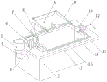
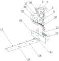
Fig. 1 is a schematic diagram of the overall structure of an electrophoresis tank with an anti-precipitation structure according to the present invention;
fig. 2 is a schematic top view of an electrophoresis tank with an anti-precipitation structure according to the present invention;
FIG. 3 is a cross-sectional view taken along line A-A in FIG. 2 of an electrophoresis tank containing an anti-settling structure according to the present invention;
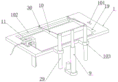
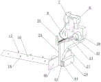
fig. 4 is a schematic structural view of a fixing table in an electrophoresis tank of an electrophoresis line with an anti-precipitation structure according to the present invention;
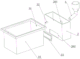
fig. 5 is a schematic diagram showing an assembly structure of an electrophoresis cell in an electrophoresis line electrophoresis tank with an anti-sedimentation structure according to the present invention;
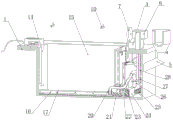
fig. 6 is a schematic diagram of an internal structure of an electrophoresis tank with an anti-precipitation structure according to the present invention;
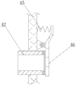
FIG. 7 is a side view of a housing structure of a power impact barrel of an electrophoresis tank with an anti-sedimentation structure according to the present invention;
fig. 8 is a cross-sectional view of a check valve in an electrophoresis tank of an electrophoresis line with an anti-settling structure according to the present invention;
FIG. 9 is a schematic diagram showing an agitating mechanism in an electrophoresis tank of an electrophoresis line with an anti-sedimentation structure according to the present invention;
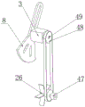
fig. 10 is a schematic diagram of the bottom structure of a triangular tube in an electrophoresis tank with an anti-precipitation structure according to the present invention.
In the figure: 1. a fixed workbench; 101. perforating the belt; 102. a step clamping hole; 103. a guide ring; 2. an auxiliary liquid storage bin; 201. an inclined jack; 202. a rectangular hole; 3. a bearing seat; 4. a valve; 5. a charging hopper; 6. a speed reducing motor; 7. a flywheel; 8. a swinging rod; 9. an electric push rod; 10. a U-shaped bracket; 11. an electrode fixing frame; 12. a power line; 13. a wire fixing ring; 14. electrode strips; 15. a working groove; 16. a triangular tube; 17. a U-shaped tube; 18. a direct injection disturbance tube; 19. a notch; 20. a communicating pipe; 21. a conveying hose; 22. perforating; 23. a connecting rod; 24. a slot-type slide rail; 25. a heating device; 26. impeller grid plates; 27. a driven pulley; 28. a conveyor belt; 29. a guide rod; 30. positioning the protruding blocks; 31. a plug hole; 32. an overflow pipe; 33. a connection frame; 34. connecting a blocking block; 35. a rack push rod; 36. a bar-shaped hole; 37. a fixing frame; 38. a power impact barrel; 39. a guide rail; 40. a sliding baffle; 41. a roller; 42. a valve tube; 43. a reciprocating ejector rod; 44. a boss slider; 45. a return spring; 46. sealing the baffle cover; 47. a sliding bearing; 48. a driving pulley; 49. a movable shaft; 50. a cleaning rod.
Detailed Description
The following description of the embodiments of the present invention will be made clearly and completely with reference to the accompanying drawings, in which it is apparent that the embodiments described are only some embodiments of the present invention, but not all embodiments.
Referring to fig. 1-10, an electrophoresis tank with an anti-sedimentation structure comprises a fixed workbench 1 with an integral rectangular structure, wherein a step clamping hole 102 is formed in the fixed workbench 1, an electrophoresis tank is fixed in the step clamping hole 102 through screws, guide rings 103 are fixed on the back surface of the fixed workbench 1 close to two ends, guide rods 29 are connected in a sliding manner in the two guide rings 103, and the guide rods 29 can only vertically slide up and down along with a U-shaped bracket 10; the same U-shaped bracket 10 extending to the upper part of the working groove 15 which is the electric swimming pool is fixed between the top ends of the two guide rods 29, the electric swimming pool comprises two auxiliary liquid storage bins 2 and the working groove 15, the bottoms of the two auxiliary liquid storage bins are communicated with each other, and the electrode battens 14 extending into the bottoms are arranged on the inner walls of the working groove 15; the electrophoresis rack is matched with the electrophoresis rack to connect the anode and the cathode; the bottom of the auxiliary liquid storage bin 2 is fixedly provided with a groove-shaped sliding rail 24 with an opening facing the communicating position, a boss sliding block 44 is connected in a sliding groove of the groove-shaped sliding rail 24 in a sliding way, a vertical connecting rod 23 is fixed on one side of the boss sliding block 44 away from the groove bottom, a connecting block 34 which is horizontally arranged is fixed on one side of the bottom of the connecting rod 23 close to the working groove 15, one end of the connecting block 34 away from the connecting rod 23 is sheathed with a triangular pipe 16, the lower surface of the triangular pipe 16 is parallel to the groove bottom of the working groove 15, the other two inclined surfaces of the triangular pipe 16 are provided with water outlets which are distributed equidistantly, one end of the triangular pipe 16 close to the connecting block 34 is spliced with a communicating pipe 20, a pipe orifice at the top end of the communicating pipe 20 is spliced with a conveying hose 21, and the connecting rod 23 is provided with a perforation 22 with a diameter matched with the conveying hose 21; through setting up the gliding triangular tube 16 in working tank 15 bottom, not only can intermittent type nature turn the electrophoretic fluid after the bottom deposit for the coating of deposit in the bottom upwards gushes out, cooperates the outward blowout liquid of jack of triangular tube 16 outer wall from time to time, can accelerate the inside liquid circulation of working tank 15, improves the homogeneity of coating ion.
In the invention, one end of the upper surface of a fixed workbench 1 far away from an auxiliary liquid storage bin 2 is fixed with an electrode fixing frame 11 through a screw, an electrode lath 14 is clamped at the end part of the electrode fixing frame 11, a screw hole is formed in a top flat plate of the electrode lath 14, a wire fixing ring 13 is fixed with the screw hole through the screw, and a power wire 12 is fixed on the outer wall of the wire fixing ring 13; through setting up the electrode lath 14 that stretches into working tank 15 bottom of the pool department, can let electrode lath 14 dismantle more convenient, and electrode lath 14 pastes the inner wall downwardly extending at working tank 15, reduces the occupation to working tank 15 inner space.
Referring to fig. 4,U, two rams are arranged at one end of the bracket 10 far away from the guide rod 29, positioning lugs 30 are fixed on the upper surfaces of the two rams, the positioning lugs 30 are positioned right above the center line of the working groove 15, and an electric push rod 9 is fixed in the middle position of the lower surface of the U-shaped bracket 10; the top end of the electric push rod 9 is provided with a bayonet slot which is matched with the thickness of the U-shaped bracket 10; through the U-shaped bracket 10 with the positioning convex blocks 30, the electrophoresis rack with the articles to be electrophoresed can be conveniently hung on the U-shaped bracket 10 during use, and then the electrophoresis rack is sunk into the working groove 15 for electrophoresis.
In the invention, an ultrasonic oscillation mechanism is arranged at the bottom of the working groove 15 near the side surface, and the ultrasonic oscillation mechanism comprises a vibration rod arranged at the corner; through the ultrasonic vibration mechanism that sets up, can accelerate the circulation effect of inside electrophoresis liquid, reduce the probability that the coating was sunk.
Referring to fig. 5, rectangular holes 202 corresponding to each other and congruent are respectively formed near the bottom of the opposite sides of the working tank 15 and the auxiliary liquid storage bin 2, and the same connecting frame 33 is communicated between the two rectangular holes 202; the side wall of the working tank 15 is communicated with the auxiliary liquid storage bin 2 near the top end, and the side walls of the working tank 15 and the auxiliary liquid storage bin 2 are provided with inserting holes 31 with diameters matched with those of the overflow pipes 32; the outer wall of the connecting block 34 is sleeved with a sliding baffle 40 near the edge of the connecting frame 33, and the side surface of the sliding baffle 40 is close to the end part of the connecting frame 33; the deposited coating material can be prevented from flowing from the bottom into the auxiliary reservoir 2.
Referring to fig. 6 to 7, a rack push rod 35 horizontally arranged is fixed at the top end of the connecting rod 23, a sliding groove is formed in the lower surface of the rack push rod 35, hanging rods are fixed above two ends of the rack push rod 35 on the lower surface of the fixed workbench 1, a guide rail 39 is fixed between the bottom ends of the two hanging rods, and the rack push rod 35 is connected to the guide rail 39 in a sliding manner; a gap 19 is formed in the upper surface of the fixed workbench 1 above the rack push rod 35, a bearing seat 3 is fixed in the middle of the upper surface of the fixed workbench 1 at the edge of the gap 19, a movable shaft 49 is connected in a rotating manner in the bearing seat 3, and two ends of the movable shaft 49 are respectively sleeved and fixed with a swinging rod 8 and a driving belt pulley 48; a sector toothed plate is reserved at the bottom end of the swinging rod 8, the bottom end of the sector toothed plate is meshed with the rack push rod 35, a speed reduction motor 6 is fixed on the upper surface of the fixed workbench 1 above the bearing seat 3, a flywheel 7 is fixed on the top end of an output shaft of the speed reduction motor 6, a bump is fixed at the position, close to the edge, of one side, far away from the speed reduction motor 6, of the flywheel 7, and a bar-shaped hole 36 with the aperture matched with the bump is formed in the position, above the movable shaft 49, of the swinging rod 8; through the combination of the gear motor 6 and the swinging rod 8, the triangular pipe 16 fixed below the connecting rod 23 can move back and forth, and the electrophoresis liquid at the bottom of the working groove 15 can be turned over.
Referring to fig. 6-7, a fixing frame 37 is fixed on the lower surface of the fixed workbench 1 above one end of the auxiliary liquid storage bin 2, a power impact barrel 38 is fixed in the fixing frame 37, an opening of the power impact barrel 38 faces to the rack push rod 35, a piston plate is slidably connected to the inner wall of the opening of the power impact barrel 38, a reciprocating push rod 43 which is parallel to the rack push rod 35 and fixed with the rack push rod 35 is fixed in the middle of the piston plate, a hose connector is inserted into one end of the power impact barrel 38 away from the opening, and one end of the conveying hose 21 away from the triangular prism 16 is connected with the hose connector through a sliding baffle 40 and a connecting rod 23; along with intermittent reciprocating impact of the rack push rod 35, the piston plate can be driven to reciprocate, impact water flow is generated, and electrophoresis liquid can be sprayed out of the jack of the triangular pipe 16 by matching with the arrangement of the conveying hose 21, so that a flow-around effect is formed; a cleaning rod 50 is fixed at the bottom of the triangular pipe 16; and one side of the side wall of the auxiliary liquid storage bin 2 far away from the working groove 15 is provided with an inclined jack 201, an addition funnel 5 is inserted into the inclined jack 201, and a valve 4 is arranged in the addition funnel 5.
Referring to fig. 7, the water outlet holes on two sides of the triangular pipe 16 are respectively inserted with a direct-injection disturbing pipe 18 and a U-shaped pipe 17; through the arranged row of direct-injection disturbing flow pipes 18 and U-shaped pipes 17, the impact effect of the power impact barrel 38 is optimal when the triangular pipes 16 move at the corner of one side, high-speed jet flow can be generated, and the internal circulation effect of electrophoresis liquid is improved.
Referring to fig. 7-8, a valve pipe 42 is embedded on the piston plate, one end of the valve pipe 42 close to the barrel bottom is hinged with a sealing baffle cover 46, and a return spring 45 is fixed between one end of the sealing baffle cover 46 far away from the valve pipe 42 and the piston plate; the extraction cycle effect is enhanced by the provision of the valve tube 42.
Referring to fig. 3, 6 and 9, a heating device 25 is further arranged at the bottom of the auxiliary liquid storage bin 2, an agitating device is arranged above the heating device 25, the agitating device comprises a sliding bearing 47 fixed on the inner wall of the auxiliary liquid storage bin 2 transversely, a long shaft rod is rotatably connected in the middle of the sliding bearing 47, driven pulleys 27 in transmission connection with a driving pulley 48 are respectively arranged on the long shaft rod, a same conveyor belt 28 is wound between the circumferential outer wall of the driving pulley 48 and the circumferential outer wall of the driven pulley 27, an impeller grid plate 26 is further fixed at the end part of the long shaft rod, and a belt perforation 101 matched with the conveyor belt 28 is formed in the fixed workbench 1; roller grooves are formed in the upper surface and the lower surface of the boss sliding block 44 and close to four corners, and rollers 41 are arranged in the roller grooves; by this arrangement, the circulation effect of the liquid in the auxiliary liquid storage bin 2 can be accelerated, and the heated electrophoretic liquid can be rapidly disturbed by the impeller grid plate 26 driven to rotate by the movable shaft 49 when in use, so that the electrophoretic liquid in the distance of the auxiliary liquid storage bin 2 can be rapidly circulated to the vicinity of the heating device 25, and the solid powder coating just added can be rapidly fused into the electrophoretic liquid.
Before the device is used, the ion quantity of the coating in the electrophoresis liquid or the density of the electrophoresis liquid containing the coating is controlled to be balanced, then a workpiece to be electrophoresed is fixed on an electrophoresis frame, and the electrophoresis frame is electrified; then hanging the electrophoresis rack on the U-shaped bracket 10, and finally controlling the extension rod of the electric push rod 9 below the U-shaped bracket 10 to shrink; at this time, the electrophoresis rack is immersed into the electrophoresis liquid in the working tank 15 along with the lowering of the U-shaped bracket 10; at this time, the motor lath 14 at the end part of the working groove 15 is electrified; meanwhile, through the combination of the gear motor 6 and the swinging rod 8, the triangular pipe 16 fixed below the connecting rod 23 can move back and forth, and the electrophoresis liquid at the bottom of the working groove 15 can be turned over at regular time; along with intermittent quick reciprocating impact of the rack push rod 35, the piston plate is driven to reciprocate, then the power impact barrel 38 generates impact water flow, and electrophoresis liquid which is not yet electrophoresed can be ejected from the jack of the triangular pipe 16, namely the U-shaped pipe 17 and the direct-injection turbulent pipe 18, so as to form a streaming effect; finally, through the arranged row of direct-injection disturbing flow pipes 18 and U-shaped pipes 17, the impact effect of the power impact barrel 38 is optimal when the triangular pipes 16 move at the corner of one side, high-speed jet flow can be generated, and the internal circulation effect of the electrophoresis liquid is improved.
The foregoing is only a preferred embodiment of the present invention, but the scope of the present invention is not limited thereto, and any person skilled in the art, who is within the scope of the present invention, should make equivalent substitutions or modifications according to the technical scheme of the present invention and the inventive concept thereof, and should be covered by the scope of the present invention.
Claims (10)
1. The utility model provides an electrophoresis line electrophoresis tank that contains anti-sedimentation structure, includes fixed workstation (1) of whole rectangle structure, open on fixed workstation (1) has ladder draw-in hole (102), and be provided with the electrophoresis tank in ladder draw-in hole (102), the back of fixed workstation (1) is close to both ends and all is fixed with guide ring (103), and all sliding connection has guide bar (29) in two guide rings (103), be fixed with the same U-shaped bracket (10) that stretches into above the electrophoresis tank between the top of two guide bar (29), its characterized in that, the electrophoresis tank includes auxiliary stock house (2) and working tank (15) that two bottoms are intercommunicated, the inner wall of working tank (15) is provided with electrode lath (14) that stretch into the bottom; and the bottom of supplementary stock solution storehouse (2) is fixed with opening towards groove type slide rail (24) of intercommunication department, and the spout sliding connection of groove type slide rail (24) has boss slider (44), and one side that boss slider (44) kept away from the tank bottom is fixed with vertical connecting rod (23), and one side that the bottom of connecting rod (23) is close to operating groove (15) is fixed with connection sprue (34) that the level set up, the one end that connecting sprue (34) kept away from connecting rod (23) has cup jointed triangular pipe (16), and the lower surface of triangular pipe (16) is parallel to each other with the tank bottom of operating groove (15), all opens the apopore that the equidistance distributes on two other inclined planes of triangular pipe (16), and triangular pipe (16) are close to the one end grafting of connecting sprue (34) has communicating pipe (20), and the top mouth of pipe department grafting of communicating pipe (20) has conveying hose (21), opens on connecting rod (23) has perforation (22) of diameter and conveying hose (21) looks adaptation.
2. The electrophoresis tank with the anti-precipitation structure according to claim 1, wherein one end, far away from the auxiliary liquid storage bin (2), of the upper surface of the fixing workbench (1) is fixedly provided with an electrode fixing frame (11) through a screw, an electrode strip (14) is clamped at the end part of the electrode fixing frame (11), a screw hole is formed in a top flat plate of the electrode strip (14), an electric wire fixing ring (13) is fixed to the screw hole through the screw, and a power wire (12) is fixed to the outer wall of the electric wire fixing ring (13).
3. The electrophoresis tank with the anti-sedimentation structure according to claim 1, wherein one end of the U-shaped bracket (10) far away from the guide rod (29) is provided with two pickers, the upper surfaces of the two pickers are respectively fixed with a positioning lug (30), the positioning lug (30) is positioned right above the central line of the working tank (15), and an electric push rod (9) is fixed in the middle position of the lower surface of the U-shaped bracket (10); and the top end of the electric push rod (9) is provided with a bayonet slot which is matched with the thickness of the U-shaped bracket (10).
4. An electrophoresis tank containing an anti-sedimentation structure according to claim 1 wherein the tank bottom of the working tank (15) is provided with an ultrasonic vibration mechanism near the side face, and the ultrasonic vibration mechanism comprises a vibration rod arranged at the corner.
5. The electrophoresis tank with the anti-sedimentation structure according to claim 1, wherein the opposite sides of the working tank (15) and the auxiliary liquid storage bin (2) are provided with corresponding and congruent rectangular holes (202) near the bottom, and the two rectangular holes (202) are communicated with one connecting frame (33); the side wall of the working groove (15) is close to the top end and is communicated with the auxiliary liquid storage bin (2) through the same overflow pipe (32), and the side walls of the working groove (15) and the auxiliary liquid storage bin (2) are provided with splicing holes (31) with the diameters matched with those of the overflow pipe (32); the outer wall of the connecting block (34) is close to the edge of the connecting frame (33) and is sleeved with a sliding baffle (40), and the side surface of the sliding baffle (40) is close to the end part of the connecting frame (33).
6. The electrophoresis tank with the anti-sedimentation structure according to claim 1, characterized in that a rack push rod (35) horizontally arranged is fixed at the top end of the connecting rod (23), a slide groove is formed on the lower surface of the rack push rod (35), hanging rods are fixed above two ends of the rack push rod (35) on the lower surface of the fixed workbench (1), a guide rail (39) is fixed between the bottom ends of the two hanging rods, and the rack push rod (35) is connected to the guide rail (39) in a sliding manner; a gap (19) is formed in the upper surface of the fixed workbench (1) above the rack push rod (35), a bearing seat (3) is fixed in the middle of the upper surface of the fixed workbench (1) at the edge of the gap (19), a movable shaft (49) is rotationally connected to the bearing seat (3), and two ends of the movable shaft (49) are respectively sleeved and fixed with a swinging rod (8) and a driving belt pulley (48); the bottom of swinging rod (8) is reserved and is had sector pinion rack, and the bottom of sector pinion rack and rack push rod (35) intermesh, and the upper surface of fixed worktable (1) is located the top of bearing frame (3) and is fixed with gear motor (6), and gear motor (6) output shaft top is fixed with flywheel (7), and one side that gear motor (6) were kept away from to flywheel (7) is close to the edge and is fixed with the lug, and swinging rod (8) are located the top position of loose axle (49) and open bar hole (36) that have aperture and lug looks adaptation.
7. Electrophoresis tank with anti-sedimentation structure according to claim 6 characterized in that the lower surface of the fixed workbench (1) is fixed with a fixed frame (37) above one end of the auxiliary liquid storage bin (2), the inside of the fixed frame (37) is fixed with a power impact barrel (38), the opening of the power impact barrel (38) faces to the rack push rod (35), the inner wall of the opening of the power impact barrel (38) is slidingly connected with a piston plate, the middle of the piston plate is fixed with a reciprocating push rod (43) which is parallel to the rack push rod (35) and is fixed with the rack push rod (35), one end of the power impact barrel (38) far away from the opening is spliced with a hose joint, and one end of the conveying hose (21) far away from the triangular prism (16) is connected with the hose joint by penetrating through the sliding baffle (40) and the connecting rod (23); a cleaning rod (50) is fixed at the bottom of the triangular pipe (16); and one side of the side wall of the auxiliary liquid storage bin (2) far away from the working groove (15) is provided with an inclined jack (201), a charging funnel (5) is inserted into the inclined jack (201), and a valve (4) is arranged in the charging funnel (5).
8. The electrophoresis tank with the anti-sedimentation structure as claimed in claim 7, wherein the water outlet holes on two sides of the triangular tube (16) are respectively inserted with a direct-injection disturbing tube (18) and a U-shaped tube (17).
9. The electrophoresis tank with the anti-sedimentation structure according to claim 7, wherein a valve tube (42) is embedded on the piston plate, one end of the valve tube (42) close to the bottom of the tank is hinged with a sealing baffle cover (46), and a return spring (45) is fixed between one end of the sealing baffle cover (46) far away from the valve tube (42) and the piston plate.
10. The electrophoresis tank with the anti-sedimentation structure according to claim 7, wherein a heating device (25) is further arranged at the bottom of the auxiliary liquid storage bin (2), an agitating device is arranged above the heating device (25), the agitating device comprises a sliding bearing (47) fixed on the inner wall of the auxiliary liquid storage bin (2) transversely, a long shaft rod is rotatably connected in the middle of the sliding bearing (47), driven pulleys (27) in transmission connection with a driving pulley (48) are respectively arranged on the long shaft rod, a same conveyor belt (28) is wound between the circumferential outer wall of the driving pulley (48) and the circumferential outer wall of the driven pulley (27), an impeller grid plate (26) is further fixed at the end part of the long shaft rod, and a belt perforation (101) matched with the conveyor belt (28) is formed on the fixed workbench (1); roller grooves are formed in the positions, close to four corners, of the upper surface and the lower surface of the boss sliding block (44), and rollers (41) are arranged in the roller grooves.
Priority Applications (1)
| Application Number | Priority Date | Filing Date | Title |
|---|---|---|---|
| CN202310390114.0A CN116103723B (en) | 2023-04-13 | 2023-04-13 | Electrophoresis line electrophoresis tank containing anti-precipitation structure |
Applications Claiming Priority (1)
| Application Number | Priority Date | Filing Date | Title |
|---|---|---|---|
| CN202310390114.0A CN116103723B (en) | 2023-04-13 | 2023-04-13 | Electrophoresis line electrophoresis tank containing anti-precipitation structure |
Publications (2)
| Publication Number | Publication Date |
|---|---|
| CN116103723A true CN116103723A (en) | 2023-05-12 |
| CN116103723B CN116103723B (en) | 2023-07-14 |
Family
ID=86264135
Family Applications (1)
| Application Number | Title | Priority Date | Filing Date |
|---|---|---|---|
| CN202310390114.0A Active CN116103723B (en) | 2023-04-13 | 2023-04-13 | Electrophoresis line electrophoresis tank containing anti-precipitation structure |
Country Status (1)
| Country | Link |
|---|---|
| CN (1) | CN116103723B (en) |
Citations (11)
| Publication number | Priority date | Publication date | Assignee | Title |
|---|---|---|---|---|
| CN102650071A (en) * | 2011-02-25 | 2012-08-29 | 苏州柳溪机电工程有限公司 | Electrophoresis transfer tank |
| CN207235907U (en) * | 2017-09-15 | 2018-04-17 | 田春火 | A kind of agricultural spraying machine |
| CN107990679A (en) * | 2017-12-28 | 2018-05-04 | 新昌县长城空调部件有限公司 | A kind of dryer of homogeneous heating |
| CN207659536U (en) * | 2017-12-26 | 2018-07-27 | 天津市垠昊鑫科技发展有限公司 | A kind of cathode electrophoresis equipment |
| CN208815145U (en) * | 2018-07-23 | 2019-05-03 | 浙江铭孚金属涂装科技有限公司 | A kind of spray equipment in electrophoresis coating technique |
| CN110230085A (en) * | 2019-03-21 | 2019-09-13 | 襄阳市志达海成科技实业有限公司 | A kind of anti-settler of double-colored electrophoresis line electrophoresis tank circulation |
| CN212688208U (en) * | 2020-08-03 | 2021-03-12 | 嵊州市西鲍电泳有限公司 | Two-color electrophoresis line electrophoresis tank circulation anti-precipitation device |
| CN213295535U (en) * | 2020-10-20 | 2021-05-28 | 常州市武进信和精密机械有限公司 | Electrophoresis tank for automobile electrophoresis coating |
| CN113584559A (en) * | 2021-09-29 | 2021-11-02 | 山东阳成生物科技有限公司 | Intelligent electrophoresis production line electrophoresis tank circulating device |
| CN214830734U (en) * | 2021-06-08 | 2021-11-23 | 江苏领创机械有限公司 | Multifunctional electrophoresis tank |
| CN215628375U (en) * | 2021-09-18 | 2022-01-25 | 江西南亚铝业有限公司 | Electrophoresis spraying device of anticorrosive aluminum alloy ex-trusions |
-
2023
- 2023-04-13 CN CN202310390114.0A patent/CN116103723B/en active Active
Patent Citations (11)
| Publication number | Priority date | Publication date | Assignee | Title |
|---|---|---|---|---|
| CN102650071A (en) * | 2011-02-25 | 2012-08-29 | 苏州柳溪机电工程有限公司 | Electrophoresis transfer tank |
| CN207235907U (en) * | 2017-09-15 | 2018-04-17 | 田春火 | A kind of agricultural spraying machine |
| CN207659536U (en) * | 2017-12-26 | 2018-07-27 | 天津市垠昊鑫科技发展有限公司 | A kind of cathode electrophoresis equipment |
| CN107990679A (en) * | 2017-12-28 | 2018-05-04 | 新昌县长城空调部件有限公司 | A kind of dryer of homogeneous heating |
| CN208815145U (en) * | 2018-07-23 | 2019-05-03 | 浙江铭孚金属涂装科技有限公司 | A kind of spray equipment in electrophoresis coating technique |
| CN110230085A (en) * | 2019-03-21 | 2019-09-13 | 襄阳市志达海成科技实业有限公司 | A kind of anti-settler of double-colored electrophoresis line electrophoresis tank circulation |
| CN212688208U (en) * | 2020-08-03 | 2021-03-12 | 嵊州市西鲍电泳有限公司 | Two-color electrophoresis line electrophoresis tank circulation anti-precipitation device |
| CN213295535U (en) * | 2020-10-20 | 2021-05-28 | 常州市武进信和精密机械有限公司 | Electrophoresis tank for automobile electrophoresis coating |
| CN214830734U (en) * | 2021-06-08 | 2021-11-23 | 江苏领创机械有限公司 | Multifunctional electrophoresis tank |
| CN215628375U (en) * | 2021-09-18 | 2022-01-25 | 江西南亚铝业有限公司 | Electrophoresis spraying device of anticorrosive aluminum alloy ex-trusions |
| CN113584559A (en) * | 2021-09-29 | 2021-11-02 | 山东阳成生物科技有限公司 | Intelligent electrophoresis production line electrophoresis tank circulating device |
Also Published As
| Publication number | Publication date |
|---|---|
| CN116103723B (en) | 2023-07-14 |
Similar Documents
| Publication | Publication Date | Title |
|---|---|---|
| CN116103723B (en) | Electrophoresis line electrophoresis tank containing anti-precipitation structure | |
| CN212129819U (en) | Novel building outer wall whitewashes equipment | |
| CN218901528U (en) | Mixing stirring device | |
| CN214115761U (en) | Nut surface electroplating device | |
| CN214766346U (en) | Be used for energy-conserving coating recovery unit | |
| CN212559407U (en) | Filling equipment is used in water based paint production | |
| CN213806414U (en) | Plastering device for building external wall | |
| CN110230085B (en) | Two-color electrophoresis line electrophoresis tank circulation anti-precipitation device | |
| CN207659536U (en) | A kind of cathode electrophoresis equipment | |
| CN216099884U (en) | Feeding device applicable to glass fiber reinforced plastic production | |
| CN220952129U (en) | Metal surface electroplating equipment | |
| CN212979568U (en) | Printing ink circulating device | |
| CN208776863U (en) | Zincing passivation mechanism | |
| CN211570828U (en) | Electrolyte recovery unit for metal mold electroplating processing | |
| CN218358787U (en) | Additive mixing and storing device | |
| CN220760209U (en) | Porcelain plate painting glaze cleaning device | |
| CN211523966U (en) | Waterproof material round brush | |
| CN213977930U (en) | A novel electrophoresis coating production line for auto-parts electrophoresis coating | |
| CN215976089U (en) | A electrophoresis cell for steel surface machining | |
| CN220963693U (en) | Lithium battery electrolyte filling device | |
| CN217248269U (en) | Stirring barrel for interior decoration | |
| CN209911286U (en) | High-end plate electroplating experiment groove testing device | |
| CN217819895U (en) | Window limit infiltration testing arrangement is used in engineering supervision | |
| CN214179505U (en) | Automatic cylinder brush head of feed | |
| CN219430155U (en) | Energy-saving electrophoresis device for electrophoresis line |
Legal Events
| Date | Code | Title | Description |
|---|---|---|---|
| PB01 | Publication | ||
| PB01 | Publication | ||
| SE01 | Entry into force of request for substantive examination | ||
| SE01 | Entry into force of request for substantive examination | ||
| GR01 | Patent grant | ||
| GR01 | Patent grant |