CN116093538A - Electrode assembly, electrochemical device, and electronic device - Google Patents
Electrode assembly, electrochemical device, and electronic device Download PDFInfo
- Publication number
- CN116093538A CN116093538A CN202310361296.9A CN202310361296A CN116093538A CN 116093538 A CN116093538 A CN 116093538A CN 202310361296 A CN202310361296 A CN 202310361296A CN 116093538 A CN116093538 A CN 116093538A
- Authority
- CN
- China
- Prior art keywords
- layer
- beads
- electrode assembly
- spinning
- average
- Prior art date
- Legal status (The legal status is an assumption and is not a legal conclusion. Google has not performed a legal analysis and makes no representation as to the accuracy of the status listed.)
- Granted
Links
Images

Classifications
-
- H—ELECTRICITY
- H01—ELECTRIC ELEMENTS
- H01M—PROCESSES OR MEANS, e.g. BATTERIES, FOR THE DIRECT CONVERSION OF CHEMICAL ENERGY INTO ELECTRICAL ENERGY
- H01M50/00—Constructional details or processes of manufacture of the non-active parts of electrochemical cells other than fuel cells, e.g. hybrid cells
- H01M50/40—Separators; Membranes; Diaphragms; Spacing elements inside cells
- H01M50/409—Separators, membranes or diaphragms characterised by the material
- H01M50/443—Particulate material
-
- H—ELECTRICITY
- H01—ELECTRIC ELEMENTS
- H01M—PROCESSES OR MEANS, e.g. BATTERIES, FOR THE DIRECT CONVERSION OF CHEMICAL ENERGY INTO ELECTRICAL ENERGY
- H01M10/00—Secondary cells; Manufacture thereof
- H01M10/05—Accumulators with non-aqueous electrolyte
- H01M10/052—Li-accumulators
- H01M10/0525—Rocking-chair batteries, i.e. batteries with lithium insertion or intercalation in both electrodes; Lithium-ion batteries
-
- H—ELECTRICITY
- H01—ELECTRIC ELEMENTS
- H01M—PROCESSES OR MEANS, e.g. BATTERIES, FOR THE DIRECT CONVERSION OF CHEMICAL ENERGY INTO ELECTRICAL ENERGY
- H01M4/00—Electrodes
- H01M4/02—Electrodes composed of, or comprising, active material
- H01M4/13—Electrodes for accumulators with non-aqueous electrolyte, e.g. for lithium-accumulators; Processes of manufacture thereof
-
- H—ELECTRICITY
- H01—ELECTRIC ELEMENTS
- H01M—PROCESSES OR MEANS, e.g. BATTERIES, FOR THE DIRECT CONVERSION OF CHEMICAL ENERGY INTO ELECTRICAL ENERGY
- H01M50/00—Constructional details or processes of manufacture of the non-active parts of electrochemical cells other than fuel cells, e.g. hybrid cells
- H01M50/40—Separators; Membranes; Diaphragms; Spacing elements inside cells
- H01M50/409—Separators, membranes or diaphragms characterised by the material
- H01M50/44—Fibrous material
-
- H—ELECTRICITY
- H01—ELECTRIC ELEMENTS
- H01M—PROCESSES OR MEANS, e.g. BATTERIES, FOR THE DIRECT CONVERSION OF CHEMICAL ENERGY INTO ELECTRICAL ENERGY
- H01M50/00—Constructional details or processes of manufacture of the non-active parts of electrochemical cells other than fuel cells, e.g. hybrid cells
- H01M50/40—Separators; Membranes; Diaphragms; Spacing elements inside cells
- H01M50/46—Separators, membranes or diaphragms characterised by their combination with electrodes
-
- H—ELECTRICITY
- H01—ELECTRIC ELEMENTS
- H01M—PROCESSES OR MEANS, e.g. BATTERIES, FOR THE DIRECT CONVERSION OF CHEMICAL ENERGY INTO ELECTRICAL ENERGY
- H01M4/00—Electrodes
- H01M4/02—Electrodes composed of, or comprising, active material
- H01M2004/026—Electrodes composed of, or comprising, active material characterised by the polarity
- H01M2004/028—Positive electrodes
-
- Y—GENERAL TAGGING OF NEW TECHNOLOGICAL DEVELOPMENTS; GENERAL TAGGING OF CROSS-SECTIONAL TECHNOLOGIES SPANNING OVER SEVERAL SECTIONS OF THE IPC; TECHNICAL SUBJECTS COVERED BY FORMER USPC CROSS-REFERENCE ART COLLECTIONS [XRACs] AND DIGESTS
- Y02—TECHNOLOGIES OR APPLICATIONS FOR MITIGATION OR ADAPTATION AGAINST CLIMATE CHANGE
- Y02E—REDUCTION OF GREENHOUSE GAS [GHG] EMISSIONS, RELATED TO ENERGY GENERATION, TRANSMISSION OR DISTRIBUTION
- Y02E60/00—Enabling technologies; Technologies with a potential or indirect contribution to GHG emissions mitigation
- Y02E60/10—Energy storage using batteries
Landscapes
- Chemical & Material Sciences (AREA)
- Chemical Kinetics & Catalysis (AREA)
- Electrochemistry (AREA)
- General Chemical & Material Sciences (AREA)
- Engineering & Computer Science (AREA)
- Materials Engineering (AREA)
- Manufacturing & Machinery (AREA)
- Battery Electrode And Active Subsutance (AREA)
- Secondary Cells (AREA)
Abstract
The invention provides an electrode assembly, an electrochemical device and an electronic device, wherein the electrode assembly comprises an electrode pole piece and an isolating layer positioned on at least one surface of the electrode pole piece, the isolating layer comprises beads and fibers positioned between adjacent beads, the beads comprise a shell layer and a core wrapped by the shell layer, the shell layer comprises a binder, the core comprises filler particles, and the average sphericity S of the beads is more than or equal to 0.85. The pore diameter of the fiber of the isolating layer is reduced and the probability of damaging the fiber by filler particles in the isolating layer is obviously reduced, so that when the electrode assembly is used in an electrochemical device, the risk of short circuit caused by low isolating layer coverage rate can be reduced, and the service life and the safety performance of the electrochemical device are improved.
Description
Technical Field
The present application relates to the field of energy storage, and in particular, to an electrode assembly, an electrochemical device, and an electronic device.
Background
The lithium ion battery has the advantages of high mass energy density, long cycle life and the like, and has wide application in the consumer electronics field.
The existing lithium ion battery system is generally composed of a positive electrode plate, a negative electrode plate, a diaphragm, electrolyte and the like. Conventional separator materials, such as polyolefin materials, may shrink severely at high temperatures (> 110 ℃) or may turn over at the edges under external impact, resulting in direct contact of the positive and negative electrode sheets and thus short circuit, creating a safety hazard. In order to solve the above problems, the surface of the separator may be modified with a ceramic material or a polymer material to improve its thermal shock resistance, interfacial adhesion and chemical stability, but this increases the overall thickness of the separator, which is detrimental to the overall performance of the battery.
The problems can be effectively solved by developing a diaphragm-free technology and adopting a method for directly preparing an isolation layer on the surface of the positive electrode plate or the surface of the negative electrode plate to replace the traditional diaphragm. The technology without diaphragm has many advantages of simplifying the production process of the battery, reducing the thickness of the isolating layer to improve the energy density, improving the porosity of the isolating layer to improve the liquid-retaining capacity, and the like, and is therefore receiving attention.
The existing diaphragm-free technology mainly prepares a polymer material layer and/or a ceramic material layer on the surface of a positive electrode plate or a negative electrode plate through a solution electrostatic spinning process. The main disadvantages are as follows: the uniformity of the polymer material layer is poor, and the weight and the thickness of the unit area are greatly different; the aperture of the polymer material layer is larger, so that the short circuit of the battery core is easy to be caused; functional fillers often have sharp corners or sharp edges that can easily damage the internal structure of the polymeric material layer.
Disclosure of Invention
The invention provides an electrode assembly, an electrochemical device and an electronic device.
The first aspect of the invention provides an electrode assembly comprising an electrode sheet and an isolating layer on at least one surface of the electrode sheet, the isolating layer comprising beads and fibres between the beads, the beads comprising a shell layer and a core surrounded by the shell layer, the shell layer comprising a binder, the core comprising filler particles, the average sphericity S of the beads being greater than or equal to 0.85.
Optionally, the average sphericity of the beads satisfies at least one of the following conditions: (a) S >0.90; (b) S >0.95.
Alternatively, the number of beads having a sphericity greater than 0.8 accounts for 95% or more based on the total number of the beads.
Optionally, the average particle diameter D of the beads satisfies at least one of the following conditions: (c) 100 nm is less than or equal to D is less than or equal to 5000 nm; (D) 300.ltoreq. 300 nm.ltoreq.D.ltoreq.1500 nm.
Alternatively, the average diameter of the core is 20nm to 4000nm, and the average thickness of the shell is 20nm to 1000nm; the ratio of the average diameter of the core to the average thickness of the shell layer satisfies at least one of the following conditions: (e) 1:50 to 10:1; (f) 1:1 to 4:1.
Optionally, the ratio of the mass of the shell layer to the mass of the fiber satisfies at least one of the following conditions: (g) 1:1 to 10:1; (h) 1:1 to 5:1.
Optionally, the average diameter L of the fibers satisfies at least one of the following conditions: (i) 20. 20 nm.ltoreq.L.ltoreq.500. 500 nm; (j) 100 nm.ltoreq.L.ltoreq.200 nm.
Optionally, the area ratio of beads and fibers on the surface of the barrier layer satisfies at least one of the following conditions: (k) 4:1 to 100:1; (l) 5:1 to 10:1.
Optionally, the thickness T of the isolation layer satisfies at least one of the following conditions: (m) T is more than or equal to 5 μm and less than or equal to 15 μm; (n) T is more than or equal to 5 μm and less than or equal to 10 μm.
Optionally, the material of the fiber or the material of the shell layer satisfies at least one of the following conditions: (o) the material of the fiber or the material of the shell layer comprises at least one of an acrylate polymer, polyvinylidene fluoride, a styrene-acrylate copolymer, a vinylidene fluoride-hexafluoropropylene copolymer, an acrylonitrile-acrylate copolymer, a vinyl chloride-acrylate copolymer, or a butadiene-styrene copolymer; the material of the shell layer of (p) comprises at least one of acrylate polymer, polyvinylidene fluoride, styrene-acrylate copolymer, vinylidene fluoride-hexafluoropropylene copolymer, acrylonitrile-acrylate copolymer, vinyl chloride-acrylate copolymer or butadiene-styrene copolymer.
Alternatively, the material of the fibers or the material of the sheath may be the same or different.
Optionally, the material of the core comprises at least one of an inorganic particle, an organic particle, or a MOF material; the inorganic particles comprise SiO 2 、Al 2 O 3 At least one of boehmite and hydroxyapatite; the organic particles comprise at least one of polyethylene, polypropylene and polyethylene terephthalate; MOF materials include ZIF-8, ZIF-67, uiO-66-NH 2 At least one of them.
A second aspect of the present invention provides an electrochemical device comprising the aforementioned electrode assembly.
A third aspect of the present invention provides an electronic device comprising the aforementioned electrochemical device.
The electrode assembly of the present invention has the following advantageous effects:
the isolation layer structure with the coexisting beads and fibers can avoid short circuit caused by overlarge pore diameter of the fibers; meanwhile, the uniformity of the isolation layer can be improved; in addition, the average sphericity S of the beads is more than or equal to 0.85, so that the shell layer can be ensured to fully wrap the filler particles, sharp corners of the filler particles are passivated, and round or nearly round beads are formed, thereby avoiding the sharp corners of the filler particles from damaging fibers, improving the stability of the isolation layer, and further improving the safety performance and the cycle performance of the electrochemical device; in addition, the shell layer is made of the material comprising the binder, so that the shell layer has elasticity and can play a role in buffering when being subjected to external force, thereby avoiding damage to fibers and improving the safety performance.
Drawings
FIG. 1 is a scanning electron microscope image of a spacer layer according to an embodiment of the present invention.
Detailed Description
The invention provides an electrode assembly, an electrochemical device and an electronic device.
For the purposes of making the objects, technical solutions and advantages of the present application more apparent, the technical solutions of the present application will be clearly and completely described below in conjunction with the embodiments, and it is apparent that the described embodiments are some, but not all, embodiments of the present application. The examples of the present application should not be construed as limiting the present application.
For simplicity, only a few numerical ranges are specifically disclosed herein. However, any lower limit may be combined with any upper limit to form a range not explicitly recited in the application; and any lower limit may be combined with any other lower limit to form a range not explicitly recited herein, as may any upper limit combined with any other upper limit to form a range not explicitly recited herein. Furthermore, each separately disclosed point or individual value may itself be combined as a lower limit or upper limit with any other point or individual value or with any other lower limit or upper limit to form a range not explicitly recited in the application.
In the description herein, unless otherwise indicated, "above", "below" includes this number.
Unless otherwise indicated, terms used in the present application have well-known meanings commonly understood by those skilled in the art. Unless otherwise indicated, the numerical values of the parameters set forth in this application may be measured by various measurement methods commonly used in the art (e.g., may be tested according to the methods set forth in the examples of this application).
The list of items to which the term "at least one of," "at least one of," or other similar terms are connected may mean any combination of the listed items. For example, if items a and B are listed, the phrase "at least one of a and B" means only a; only B; or A and B. In another example, if items A, B and C are listed, then the phrase "at least one of A, B and C" means only a; or only B; only C; a and B (excluding C); a and C (excluding B); b and C (excluding A); or A, B and C. Item a may comprise a single component or multiple components. Item B may comprise a single component or multiple components. Item C may comprise a single component or multiple components.
1. Electrode assembly
One or more embodiments of the present invention provide an electrode assembly including an electrode tab and an isolation layer on at least one surface of the electrode tab. The isolation layer structure can be seen in fig. 1. The isolating layer comprises beads and fibers positioned among the beads, the beads comprise shell layers and core cores wrapped by the shell layers, the shell layers comprise binder materials, the core cores comprise filler particles, and the average sphericity S of the beads is more than or equal to 0.85. Exemplary, the beads have an average sphericity S of 0.85, 0.87, 0.90, 0.92, 0.95, 0.97, 0.98, or a range of any two of the foregoing values. In a preferred embodiment of the invention, the beads have an average sphericity S.gtoreq.0.9. In other embodiments of the invention, the beads may also have an average sphericity S of less than 0.85.
It is understood that the structure of the isolation layer where the beads and the fibers coexist can avoid short circuit caused by overlarge pore diameter of the fibers; meanwhile, the uniformity of the isolation layer can be improved; in addition, the average sphericity S of the beads is more than or equal to 0.85, so that the shell layer can be ensured to fully wrap the filler particles, sharp corners of the filler particles are passivated, and round or nearly round beads are formed, thereby avoiding the filler particles from damaging fibers, improving the stability of the isolation layer, and further improving the safety performance and the cycle performance of the electrochemical device; in addition, as the material of the shell layer comprises the binder, the shell layer has elasticity, can play a role in buffering when being subjected to external force, and further avoids fiber damage, thereby improving the safety performance.
Fig. 1 shows a scanning electron microscope image of an isolation layer. In one embodiment of the invention, see fig. 1, the beads are integrally connected to the fibers, the beads are connected by the fibers to form a string, and the different strings of beads are stacked together to form an insulation layer. Wherein, the bead is the main part of isolation layer, and the fibre can play connection and filling effect to still be favorable to improving the pliability of isolation layer.
In one embodiment of the invention, the beads have an average sphericity S >0.90.
In a preferred embodiment of the invention, the beads have an average sphericity S >0.95.
In one embodiment of the invention, the number of beads having a sphericity greater than 0.8 is 95% or more based on the total number of the beads.
It will be appreciated that the higher the sphericity of the beads and/or the more uniform the sphericity distribution, the more advantageous is the formation of a smooth and structurally stable barrier layer.
In one embodiment of the invention, the beads have an average particle size D of 100 nm to 5000 nm, and exemplary, the beads have an average particle size D of 100 nm, 200 nm, 300 nm, 500 nm, 800 nm, 1000 nm, 1500 nm, 2000 nm, 2500 nm, 3000 nm, 3500 nm, 4000 nm, 4500 nm, 5000 nm, or a range of any two of the values recited above.
It will be appreciated that when the average diameter D of the beads is too large, the gaps between the beads will also increase, and at a given separator thickness, the number of layers deposited for the beads will decrease, rendering the beads unable to adequately fill the pores of the fibers, rendering the separator unable to adequately cover the electrode sheet surface, thereby increasing the probability of short circuits occurring. When the average diameter D of the beads is too small, the shell layer cannot sufficiently coat the filler particles, so that the beneficial effects of the present invention cannot be achieved. The average particle diameter D of the beads is controlled within the above range so that the filler particles can be sufficiently passivated while the separator can sufficiently cover the electrode surface.
In a preferred embodiment of the invention, the beads have an average particle diameter D of 300 nm to 1500nm, and exemplary, the beads have an average particle diameter D of 300 nm, 350 nm, 400 nm, 450 nm, 500nm, 600 nm, 700 nm, 750 nm, 850 nm, 900 nm, 950 nm, 1000nm, 1200nm, 1500nm, or a range of any two of the values recited above.
In one embodiment of the invention, the average diameter of the core is 20nm to 4000nm, and exemplary, the average diameter of the core is 20nm, 50nm, 100nm, 200nm, 500nm, 800nm, 1000nm, 1500nm, 2000nm, 2500nm, 3000nm, 3500nm, 4000nm, or a range of any two of the foregoing values; the average thickness of the shell layer is 20nm to 1000nm, and exemplary, the average thickness of the shell layer is 20nm, 50nm, 100nm, 200nm, 500nm, 800nm, 1000nm or a range of any two of the above values.
In one embodiment of the invention, the ratio of the average diameter of the core to the average thickness of the shell is from 1:50 to 10:1, and exemplary ratios of the average diameter of the core to the average thickness of the shell are 1:50, 1:45, 1:40, 1:35, 1:30, 1:25, 1:20, 1:15, 1:10, 1:5, 1:1, 5:1, 10:1, or ranges of any two of the foregoing values.
It will be appreciated that when the thickness ratio is too small, sharp corners of the filler particles themselves cannot be sufficiently passivated, and exposed sharp corners tend to puncture the fibers, failing to maintain the integrity of the barrier layer. When the thickness ratio is too large, excessive binder coating will cause the average particle diameter of the beads to be too large, the spacing between the beads to be small or even to be squeezed, and thus a structure in which fibers coexist with spherical beads in the scheme cannot be formed. The ratio of the average diameter of the core to the average thickness of the shell is controlled in the above range, which can ensure that the isolating layer forms a structure in which fibers and spherical beads coexist and can also ensure that the filler particles are sufficiently passivated.
In a preferred embodiment of the invention, the ratio of the average diameter of the core to the average thickness of the shell is from 1:1 to 4:1, and exemplary ratios of the average diameter of the core to the average thickness of the shell are 1:1, 2:1, 3:1, 4:1, or any two of the above ranges.
In one embodiment of the invention, the ratio of the mass of the shell layer to the mass of the fiber is from 1:1 to 10:1, and exemplary ratios of the mass of the shell layer to the mass of the fiber are 1:1, 2:1, 4:1, 6:1, 7:1, 8:1, 9:1, 10:1, or ranges of any two of the foregoing values.
It can be understood that when the mass ratio of the fiber to the shell layer is too large, the fiber structure in the isolation layer is too large, and after the thermal compression of the battery, the tight packing of the fiber and the beads cannot be realized, so that the pore size distribution of the isolation layer cannot be effectively reduced. When the mass ratio of the fiber to the shell layer is too small, the filler structure is exposed, the fiber is easy to damage and even break, and the bonding effect between the beads and the fiber and between the beads is also poor, so that the bonding force between the interlayer and the pole piece is affected. The mass ratio of the fiber to the shell layer can be controlled in the above range, so that the pore size of the fiber in the isolation layer can be effectively regulated, and the full bonding between the beads and the fiber can be ensured, thereby ensuring the stability of the isolation layer.
In a preferred embodiment of the invention, the ratio of the mass of the shell layer to the mass of the fiber is from 1:1 to 5:1, and exemplary ratios of the mass of the shell layer to the mass of the fiber are 1:1, 2:1, 3:1, 4:1, 5:1 or ranges of any two of the values recited above.
In one embodiment of the invention, the average diameter L of the fibers satisfies 20 nm.ltoreq.L.ltoreq.1000 nm, and the average diameter L of the fibers is illustratively 20 nm, 50 nm, 100 nm, 150 nm, 200 nm, 250 nm, 300 nm, 350 nm, 400 nm, 450 nm, 500 nm, 600 nm, 700 nm, 800 nm, 900 nm, 1000 nm or a range of any two of the values mentioned above.
It is understood that when the average diameter L of the fiber is too large, the pore size of the separator is large, which is liable to cause local short-circuiting. When the average diameter L of the fibers is too small, particles are too densely packed, which affects the rate performance of the battery. The average diameter L of the fibers is controlled in the above range, so that the electrode assembly of the present embodiment can be ensured to be useful for improving the safety performance and the rate performance of the battery at the same time when used for forming the battery.
In a preferred embodiment of the invention, the average diameter L of the fibers satisfies 100 nm.ltoreq.L.ltoreq.500 nm, and exemplary average diameters L of the fibers are 50 nm, 60 nm, 80 nm, 100 nm, 120 nm, 140 nm, 160 nm, 180 nm, 200 nm, 220 nm, 240 nm, 260 nm, 280 nm, 320 nm, 340 nm, 360 nm, 380 nm, 420 nm, 440 nm, 460 nm, 480 nm, or a range of any two of the values mentioned above.
In one embodiment of the invention, the area ratio of beads to fibers on the surface of the barrier layer is from 4:1 to 100:1, and illustratively the area ratio of beads to fibers on the surface of the barrier layer is 4:1, 10:1, 20:1, 30:1, 40:1, 50:1, 60:1, 70:1, 80:1, 90:1, 100:1, or a range of any two of the values recited above.
It is understood that when the area ratio of the beads and the fibers is too large, i.e., the beads are excessively stacked, the porosity of the separator layer is reduced, and the effect on the rate performance of the battery is performed. When the area ratio of the beads to the fibers is too small, the beads cannot exert uniform filling of voids formed by the fiber stack, resulting in a large K value of the battery. The area ratio of the beads to the fibers is controlled within the above range, so that the electrode assembly of the present embodiment can be ensured to be useful for improving the rate performance of the battery and reducing the K value of the battery at the same time when used for forming the battery.
In a preferred embodiment of the invention, the area ratio of beads to fibers on the surface of the barrier layer is from 5:1 to 10:1, and illustratively the area ratio of beads to fibers on the surface of the barrier layer is 5:1, 6:1, 7:1, 8:1, 9:1, 10:1 or a range of any two of the values recited above.
In one embodiment of the invention, the thickness T of the barrier layer satisfies 5 μm.ltoreq.T.ltoreq.15 μm, and the thickness T of the barrier layer is exemplified by 5 μm, 6 μm, 8 μm, 10 μm, 11 μm, 12 μm, 13 μm, 14 μm, 15 μm, or a range of any two values of the above.
It can be understood that the thickness T of the isolation layer is too small, which may cause deterioration of the liquid absorbing and retaining ability, electronic insulation, tear resistance and the like of the isolation layer to the electrolyte, and the uniformity of the isolation layer may also deteriorate, even cause short circuit; if the thickness T of the separator is too large, the ion conductivity and air permeability of the separator are deteriorated, the resistance is increased, the number of layers to be wound is decreased during winding, and the capacity of the battery is reduced. The thickness T of the isolation layer is controlled within the range, so that the capacity and the power performance of the lithium ion battery are improved, and the stability and the safety performance of the lithium ion battery are improved.
In a preferred embodiment of the invention, the thickness T of the barrier layer is 8 μm.ltoreq.T.ltoreq.10 μm, and the thickness T of the barrier layer is exemplified as 5.5 μm, 6.5 μm, 7 μm, 7.5 μm, 8.5 μm, 9 μm, 9.5 μm or a range of any two values mentioned above.
In one embodiment of the present invention, the material of the fiber may further include, but is not limited to, at least one of an acrylate polymer, polyvinylidene fluoride, styrene-acrylate copolymer, vinylidene fluoride-hexafluoropropylene copolymer, acrylonitrile-acrylate copolymer, vinyl chloride-acrylate copolymer, or butadiene-styrene copolymer.
In one embodiment of the present invention, the material of the shell layer may further include, but is not limited to, at least one of an acrylate polymer, polyvinylidene fluoride, styrene-acrylate copolymer, vinylidene fluoride-hexafluoropropylene copolymer, acrylonitrile-acrylate copolymer, vinyl chloride-acrylate copolymer, or butadiene-styrene copolymer.
In one embodiment of the invention, the material of the fibers is the same as or different from the material of the shell layer.
In one embodiment of the invention, the material of the core includes, but is not limited to, at least one of an inorganic particle, an organic particle, or a MOF material. Specifically, the inorganic particles include, but are not limited to, siO 2 、Al 2 O 3 At least one of boehmite and hydroxyapatite. Specifically, the organic particles include, but are not limited to, at least one of polyethylene, polypropylene, polyethylene terephthalate. Specifically, MOF materials include, but are not limited to, ZIF-8, ZIF-67, uiO-66-NH 2 At least one of them.
The negative electrode plate comprises a negative electrode current collector and a negative electrode active material layer positioned on the negative electrode current collector, and the isolation layer is positioned on one side surface of the negative electrode active material layer, which is away from the negative electrode current collector.
In some embodiments, the negative electrode active material layer includes a binder. The binder may include: at least one of polyvinyl alcohol, carboxymethyl cellulose, hydroxypropyl cellulose, diacetyl cellulose, polyvinyl chloride, carboxylated polyvinyl chloride, polyvinyl fluoride, an ethyleneoxy-containing polymer, polyvinylpyrrolidone, polyurethane, polytetrafluoroethylene, polyvinylidene 1, 1-difluoroethylene, polyethylene, polypropylene, styrene-butadiene rubber, acrylated styrene-butadiene rubber, epoxy resin, or nylon.
In some embodiments, the anode active material layer includes a conductive material. The conductive material may include: at least one of natural graphite, artificial graphite, carbon black, acetylene black, ketjen black, carbon fiber, metal powder, metal fiber, copper, nickel, aluminum, silver or polyphenylene derivative.
In some embodiments, the negative electrode current collector may include: at least one of copper foil, nickel foil, stainless steel foil, titanium foil, nickel foam, copper foam, or a polymer substrate coated with a conductive metal.
In some embodiments, the negative electrode sheet may be obtained by: the negative electrode active material, the conductive material, and the binder are mixed in a solvent to prepare a negative electrode active material composition, and the negative electrode active material composition is coated on a negative electrode current collector. In some embodiments, the solvent may include N-methylpyrrolidone, etc., but is not limited thereto.
In some embodiments, the positive electrode tab includes a positive electrode current collector and a positive electrode active material layer on the positive electrode current collector. The separator layer is located on a surface of the positive electrode active material layer facing away from the positive electrode current collector.
In some embodiments, the positive electrode active material layer includes a positive electrode active material. The positive electrode active material may include: lithium cobalt oxide (LiCoO) 2 ) Ternary materials of lithium Nickel Cobalt Manganese (NCM), lithium iron phosphate (LiFePO) 4 ) Lithium manganate (LiMn) 2 O 4 ) At least one of them.
In some embodiments, the positive electrode active material layer further includes a binder, and optionally includes a conductive material. The binder can improve the bonding of the positive electrode active material particles to each other, and can also improve the bonding of the positive electrode active material layer to the positive electrode current collector.
In some embodiments, the binder may include: at least one of polyvinyl alcohol, hydroxypropyl cellulose, diacetyl cellulose, polyvinyl chloride, carboxylated polyvinyl chloride, polyvinyl fluoride, an ethyleneoxy-containing polymer, polyvinylpyrrolidone, polyurethane, polytetrafluoroethylene, polyvinylidene fluoride, polyethylene, polypropylene, styrene-butadiene rubber, acrylated styrene-butadiene rubber, epoxy resin, nylon.
In some embodiments, the conductive material may include: at least one of a carbon-based material, a metal-based material, a conductive polymer. In some embodiments, the carbon-based material may include at least one of natural graphite, synthetic graphite, carbon black, acetylene black, ketjen black, carbon fiber. In some embodiments, the metal-based material may include at least one of metal powder, metal fibers, copper, nickel, aluminum, silver. In some embodiments, the conductive polymer may include a polyphenylene derivative.
In some embodiments, the positive electrode current collector may be aluminum, but is not limited thereto.
The positive electrode sheet may be prepared by a preparation method well known in the art. For example, the positive electrode sheet can be obtained by: the positive electrode active material, the conductive material, and the binder are mixed in a solvent to prepare a positive electrode active material composition, and the positive electrode active material composition is coated on a positive electrode current collector. In some embodiments, the solvent may include N-methylpyrrolidone, etc., but is not limited thereto.
2. Electrolyte solution
In one or more embodiments of the invention, the electrolyte includes a lithium salt and a nonaqueous solvent.
In some embodiments of the present application, the lithium salt includes, but is not limited to, liPF 6 、LiBF 4 、LiAsF 6 、LiClO 4 、LiB(C 6 H 5 ) 4 、LiCH 3 SO 3 、LiCF 3 SO 3 、LiN(SO 2 CF 3 ) 2 、LiC(SO 2 CF 3 ) 3 、LiSiF 6 One or more of LiBOB or lithium difluoroborate.
Exemplary lithium salts may be LiPF 6 。
The nonaqueous solvent includes, but is not limited to, one or more of a carbonate compound, a carboxylate compound, or an ether compound.
Illustratively, the carbonate compounds include, but are not limited to, one or more of a chain carbonate compound, a cyclic carbonate compound, or a fluorocarbonate compound. Specifically, the chain carbonate compounds include, but are not limited to, one or more of dimethyl carbonate (DMC), diethyl carbonate (DEC), dipropyl carbonate (DPC), methylpropyl carbonate (MPC), ethylpropyl carbonate (EPC), or methylethyl carbonate (MEC); the cyclic carbonate compounds include, but are not limited to, one or more of Ethylene Carbonate (EC), propylene Carbonate (PC), butylene Carbonate (BC) or Vinyl Ethylene Carbonate (VEC); the fluorocarbonate compounds include, but are not limited to, one or more of fluoroethylene carbonate (FEC), 1, 2-difluoroethylene carbonate, 1, 2-trifluoroethylene carbonate, 1, 2-tetrafluoroethylene carbonate, 1-fluoro-2-methylethylene carbonate, 1-fluoro-1-methylethylene carbonate, 1, 2-difluoro-1-methylethylene carbonate, 1, 2-trifluoro-2-methylethylene carbonate, or trifluoromethyl ethylene carbonate.
Exemplary carboxylate compounds include, but are not limited to, one or more of methyl formate, methyl acetate, ethyl acetate, n-propyl acetate, t-butyl acetate, methyl propionate, ethyl propionate, propyl propionate, gamma-butyrolactone, decalactone, valerolactone, mevalonic acid lactone, or caprolactone.
Exemplary ether compounds include, but are not limited to, one or more of dibutyl ether, tetraglyme, diglyme, 1, 2-dimethoxyethane, 1, 2-diethoxyethane, ethoxymethoxyethane, 2-methyltetrahydrofuran, or tetrahydrofuran.
It will be appreciated that the nonaqueous solvent may also include other organic solvents such as, for example, one or more of dimethylsulfoxide, 1, 2-dioxolane, sulfolane, methylsulfanyl sulfone, 1, 3-dimethyl-2-imidazolidone, N-methyl-2-pyrrolidone, formamide, dimethylformamide, acetonitrile, trimethyl phosphate, triethyl phosphate, trioctyl phosphate or phosphate esters.
3. Electrochemical device
In one or more embodiments of the present invention, there is also provided an electrochemical device including the electrode assembly of the foregoing embodiments.
According to some embodiments of the present application, the electrochemical devices of the present application include, but are not limited to: all kinds of primary batteries, secondary batteries, fuel cells, solar cells or capacitors. In some embodiments, the electrochemical device is a lithium secondary battery. In some embodiments, lithium secondary batteries include, but are not limited to: lithium metal secondary batteries, lithium ion secondary batteries, lithium polymer secondary batteries, or lithium ion polymer secondary batteries.
In a specific example of the present invention, the electrochemical device is a lithium ion battery, and the type of the lithium ion battery is not particularly limited, and may be any type of lithium ion battery, such as button type, cylinder type, soft pack type lithium ion battery, and the like.
The process of preparing the electrochemical device is well known to those skilled in the art, and the present application is not particularly limited, and may include, for example, but not limited to, the following steps: sequentially stacking the positive electrode assembly and the negative electrode assembly, winding and folding the positive electrode assembly and the negative electrode assembly according to the need to obtain an electrode assembly with a winding structure, placing the electrode assembly into a packaging bag, injecting electrolyte into the packaging bag, and sealing to obtain an electrochemical device; or sequentially stacking the positive electrode assembly and the negative electrode assembly, fixing four corners of the whole lamination structure by using adhesive tapes to obtain the electrode assembly with the lamination structure, placing the electrode assembly into a packaging bag, injecting electrolyte into the packaging bag, and sealing to obtain the electrochemical device. In addition, an overcurrent prevention element, a guide plate, or the like may be placed in the package as needed, thereby preventing the pressure inside the electrochemical device from rising and overcharging and discharging. The packaging bag is not limited in this application, and a person skilled in the art can select according to actual needs, so long as the purpose of this application can be achieved. For example, an aluminum plastic film package may be used.
It can be understood that the positive electrode assembly and the negative electrode assembly used in the above-described method of manufacturing an electrochemical device satisfy: the positive electrode assembly includes a positive electrode tab and an isolation layer, and/or the negative electrode assembly includes a negative electrode tab and an isolation layer.
4. Electronic device
One or more embodiments of the present invention also provide an electronic device, which may be any device using the electrochemical device of the foregoing embodiments.
In some embodiments, the electronic device of the present application includes, but is not limited to: notebook computers, pen-input computers, mobile computers, electronic book players, portable telephones, portable facsimile machines, portable copiers, portable printers, headsets, video recorders, liquid crystal televisions, hand-held cleaners, portable CD-players, mini-compact discs, transceivers, electronic notebooks, calculators, memory cards, portable audio recorders, radios, stand-by power supplies, motors, automobiles, motorcycles, mopeds, bicycles, lighting fixtures, toys, game machines, watches, electric tools, flash lamps, cameras, household large-sized batteries or lithium-ion capacitors, and the like.
The present application will be described in further detail with reference to examples and comparative examples, but the present application is not limited to these examples unless departing from the gist thereof.
Examples and comparative examples
1. Preparation of negative electrode plate
Negative electrode sheets of comparative examples 1 to 3 and examples 1 to 31 were prepared as follows
Mixing negative electrode active material Graphite (Graphite), conductive carbon black (Super P) and Styrene Butadiene Rubber (SBR) according to the weight ratio of 96:1.5:2.5, and adding deionized water (H) 2 O) was used as a solvent, and the slurry was prepared to have a solid content of 0.7, and stirred uniformly. And uniformly coating the slurry on an 8 mu m negative current collector copper foil, and drying at 110 ℃ to obtain the single-sided coated negative electrode plate with the coating thickness of 55 mu m. And then, completing the steps on the back of the pole piece by a completely consistent method, and obtaining the double-sided coated negative pole piece. After the coating is completed, the pole piece is cut into (41 mm ×61 mm) specifications for use.
2. Preparation of positive electrode plate
Positive electrode sheets of comparative examples 1 to 3 and examples 1 to 31 were prepared as follows
Lithium cobalt oxide (LiCoO) as a positive electrode active material 2 ) Mixing conductive carbon black (Super P) and polyvinylidene fluoride (PVDF) according to a weight ratio of 97.5:1.0:1.5, adding N-methyl pyrrolidone (NMP) as a solvent, preparing into slurry with solid content of 0.75, and uniformly stirring. Homogenizing the slurry Coating the coating on an aluminum foil of a 10 mu m positive electrode current collector, and drying at 90 ℃ to obtain a single-sided coated positive electrode plate with the coating thickness of 50 mu m. And then, completing the steps on the back of the pole piece by a completely consistent method, and obtaining the positive pole piece with the double-sided coating. After coating is completed, the pole piece is cut into (38 mm ×58 mm) specifications for use.
3. Preparation of fibrous insulation layer
Comparative example 1
PVDF is dissolved in DMF/acetone (1:1) solvent and stirred uniformly until the viscosity of slurry is stable, thus obtaining solution A with the mass fraction of 25%; setting spinning voltage at 30kV, the diameter of a spinning nozzle at 0.41mm (a spinning needle 27G), the ejection amount per unit time at 1mL/h and the spinning time at 10h by using a solution A as a raw material to install an injection pump and adopting a method of mixing electric spinning and gas spinning, and preparing a PVDF fiber layer with the thickness of 10 mu m and the average fiber diameter of 500 nm; and spinning the solution A on the back of the pole piece in a completely consistent way, and then heating to 80 ℃ to treat 6 h to complete the crosslinking process, so as to obtain the positive pole piece with the double-sided isolation layer.
Comparative example 2
PE is dissolved in DMF/acetone (1:1) solvent and stirred uniformly until the viscosity of slurry is stable, so as to obtain a solution A with the mass fraction of 25%; setting spinning voltage at 30kV, the diameter of a spinning nozzle at 1.27mm (spinning needle 18G), the ejection amount per unit time at 1mL/h and the spinning time at 10h by using a solution A as a raw material to install an injection pump and adopting an electro-spinning and gas spinning mixed method, and preparing a PE fiber layer with the thickness of 10 mu m and the average fiber diameter of 2000 nm; and spinning the solution A on the back of the pole piece in a completely consistent way, and then heating to 80 ℃ to treat 6 h to complete the crosslinking process, so as to obtain the positive pole piece with the double-sided isolation layer.
Comparative example 3
PVDF is dissolved in DMF/acetone (1:1) solvent and stirred uniformly until the viscosity of slurry is stable, thus obtaining solution A with the mass fraction of 25%; 95% Al 2 O 3 5% PVDF was dispersed in DMF/acetone (1:1) Uniformly stirring in a solvent until the viscosity of the slurry is stable, and obtaining a solution B with the mass fraction of 25%; preparing a PVDF fiber layer with the thickness of 8 mu m by using a method of using a solution A as a raw material to fill an injection pump and mixing electric spinning and gas spinning on the surface of a positive electrode plate, setting the spinning voltage to be 30kV, setting the diameter of a spinning nozzle to be 0.41mm (a spinning needle 27G), setting the ejection amount per unit time to be 1mL/h and setting the spinning time to be 7 h; then, using a solution B as a raw material and electrospraying, a spinning voltage of 35kV, a diameter of a spinning nozzle of 0.41mm (spinning needle 27G), a discharge amount per unit time of 1mL/h, a spinning time of 3 hours, and a layer of Al 2 μm thick was sprayed on the PVDF fiber layer 2 O 3 Particles; then spinning on the other side surface of the positive pole piece by the same method; and then heating to 80 ℃ to heat treat 6 h to complete the crosslinking process, so as to obtain the positive electrode plate with the double-sided isolating layer.
Example 1
Dispersing PVDF of 5 g in 27 mL DMF solvent, stirring to uniformly disperse the solids, and then heating in an oil bath at 90 ℃ for 12 h until the solids are fully dissolved; 5 g of Al are added to the PVDF solution prepared 2 O 3 Particles and 63mL of acetone, and performing ultrasonic dispersion on the particles and the 63mL of acetone to obtain a solution A after 12 h; on the surface of the positive electrode plate, a solution A is used as a raw material and is filled into an injection pump, and through an electrospinning one-step method, the spinning voltage is set to be 35kV, the diameter of a spinning nozzle is 0.41mm (a spinning needle 27G), the ejection amount per unit time is 1mL/h, the spinning time is 10h, and a layer of bead fiber layer with the thickness of 10 mu m is prepared, wherein the average particle diameter of the bead is 500 nm, and the average fiber diameter is 100 nm. And then, preparing the solution A on the back of the pole piece by a completely consistent method, and then, heating to 80 ℃ to perform heat treatment for 6 h to complete the crosslinking process, thereby obtaining the positive pole piece with the double-sided isolation layer.
Example 2
Dispersing PVDF of 5 g in 27 mL DMF solvent, stirring to uniformly disperse the solids, and then heating in an oil bath at 90 ℃ for 12 h until the solids are fully dissolved; 5 g of SiO was added to the prepared PVDF solution 2 Particles and 63mL of acetone, and performing ultrasonic dispersion on the particles and the 63mL of acetone to obtain a solution A after 12 h; on the surface of the positive pole piece, the solution A is used as a raw material to be filled with an injection pump to pass throughThe electrospinning method was carried out in one step, the spinning voltage was set at 35kV, the diameter of the spinning nozzle was 0.41mm (spinning needle 27G), the ejection amount per unit time was 1mL/h, the spinning time was 10 hours, and a bead fiber layer having a thickness of 10 μm was prepared, the average bead diameter was 500 nm, and the average fiber diameter was 100 nm. And then, preparing the solution A on the back of the pole piece by a completely consistent method, and then, heating to 80 ℃ to perform heat treatment for 6 h to complete the crosslinking process, thereby obtaining the positive pole piece with the double-sided isolation layer.
Example 3
Dispersing PVDF of 5 g in 27 mL DMF solvent, stirring to uniformly disperse the solids, and then heating in an oil bath at 90 ℃ for 12 h until the solids are fully dissolved; adding 5 g ZIF-8 particles and 63mL acetone into the prepared PVDF solution, and performing ultrasonic dispersion on the mixture to obtain a solution A after 12 h; on the surface of the positive electrode plate, a solution A is used as a raw material and is filled into an injection pump, and through an electrospinning one-step method, the spinning voltage is set to be 35kV, the diameter of a spinning nozzle is 0.41mm (a spinning needle 27G), the ejection amount per unit time is 1mL/h, the spinning time is 10h, and a layer of bead fiber layer with the thickness of 10 mu m is prepared, wherein the average particle diameter of the bead is 500 nm, and the average fiber diameter is 100 nm. And then, preparing the solution A on the back of the pole piece by a completely consistent method, and then, heating to 80 ℃ to perform heat treatment for 6 h to complete the crosslinking process, thereby obtaining the positive pole piece with the double-sided isolation layer.
Example 4
Dispersing the PI prepolymer of 5 g in 27 mL of DMF solvent, stirring to uniformly disperse the solid, and then heating the solid in an oil bath at 90 ℃ for 12 h until the solid is fully dissolved; 5 g of Al are added to the PVDF solution prepared 2 O 3 Particles and 63mL of acetone, and performing ultrasonic dispersion on the particles and the 63mL of acetone to obtain a solution A after 12 h; on the surface of the positive electrode plate, a solution A is used as a raw material and is filled into an injection pump, and through an electrospinning one-step method, the spinning voltage is set to be 35kV, the diameter of a spinning nozzle is 0.41mm (a spinning needle 27G), the ejection amount per unit time is 1mL/h, the spinning time is 10h, and a layer of bead fiber layer with the thickness of 10 mu m is prepared, wherein the average particle diameter of the bead is 500 nm, and the average fiber diameter is 100 nm. Thereafter, solution A was prepared on the back of the pole piece in a completely consistent manner, followed by heat treatment at a temperature of 80℃for 6 h to complete the crosslinking process, i.e The positive pole piece with the isolating layer on the two sides can be obtained.
Example 5
Dispersing PVP of 5 g in 27 mL DMF solvent, stirring to uniformly disperse the solid, and then heating in an oil bath at 90 ℃ for 12 h until the solid is fully dissolved; 5 g of Al are added to the PVDF solution prepared 2 O 3 Particles and 63mL of acetone, and performing ultrasonic dispersion on the particles and the 63mL of acetone to obtain a solution A after 12 h; on the surface of the positive electrode plate, a solution A is used as a raw material and is filled into an injection pump, and through an electrospinning one-step method, the spinning voltage is set to be 35kV, the diameter of a spinning nozzle is 0.41mm (a spinning needle 27G), the ejection amount per unit time is 1mL/h, the spinning time is 10h, and a layer of bead fiber layer with the thickness of 10 mu m is prepared, wherein the average particle diameter of the bead is 500 nm, and the average fiber diameter is 100 nm. And then, preparing the solution A on the back of the pole piece by a completely consistent method, and then, heating to 80 ℃ to perform heat treatment for 6 h to complete the crosslinking process, thereby obtaining the positive pole piece with the double-sided isolation layer.
Example 6
Dispersing PVDF of 8.57 and g in 27 mL of DMF solvent, stirring to uniformly disperse the solid, and then heating the solid in an oil bath at 90 ℃ for 12 h until the solid is fully dissolved; 1.43 g of Al are added to the PVDF solution prepared 2 O 3 Particles and 63mL of acetone, and performing ultrasonic dispersion on the particles and the 63mL of acetone to obtain a solution A after 12 h; on the surface of the positive electrode plate, a solution A is used as a raw material and is filled into an injection pump, and through an electrospinning one-step method, the spinning voltage is set to be 35kV, the diameter of a spinning nozzle is 0.91mm (a spinning needle 20G), the ejection amount per unit time is 1mL/h, the spinning time is 10h, and a layer of bead fiber layer with the thickness of 10 mu m is prepared, wherein the average particle diameter of the bead is 1000 nm, and the average fiber diameter is 100 nm. And then, preparing the solution A on the back of the pole piece by a completely consistent method, and then, heating to 80 ℃ to perform heat treatment for 6 h to complete the crosslinking process, thereby obtaining the positive pole piece with the double-sided isolation layer.
Example 7
Dispersing 7.5 g PVDF in 27 mL DMF solvent, stirring to uniformly disperse the solid, and then heating in an oil bath at 90 ℃ for 12 h until the solid is fully dissolved; 2.5 g of Al are added to the PVDF solution prepared 2 O 3 Particles and 63mL of acetone, and performing ultrasonic dispersion on the particles and the 63mL of acetone to obtain a solution A after 12 h; in the positive directionThe surface of the pole piece is provided with a solution A as a raw material and is provided with an injection pump by an electrospinning one-step method, the spinning voltage is set to be 35kV, the diameter of a spinning nozzle is 0.91mm (a spinning needle head 20G), the ejection amount per unit time is 1mL/h, the spinning time is 10h, and a bead fiber layer with the thickness of 10 mu m is prepared, the average particle diameter of the bead is 1000 nm, and the average fiber diameter is 200 nm. And then, preparing the solution A on the back of the pole piece by a completely consistent method, and then, heating to 80 ℃ to perform heat treatment for 6 h to complete the crosslinking process, thereby obtaining the positive pole piece with the double-sided isolation layer.
Example 8
Dispersing PVDF of 5 g in 27 mL DMF solvent, stirring to uniformly disperse the solids, and then heating in an oil bath at 90 ℃ for 12 h until the solids are fully dissolved; 5 g of Al are added to the PVDF solution prepared 2 O 3 Particles and 63mL of acetone, and performing ultrasonic dispersion on the particles and the 63mL of acetone to obtain a solution A after 12 h; on the surface of the positive electrode plate, a solution A is used as a raw material and is filled into an injection pump, and through an electrospinning one-step method, the spinning voltage is set to be 35kV, the diameter of a spinning nozzle is 0.91mm (a spinning needle 20G), the ejection amount per unit time is 1mL/h, the spinning time is 10h, and a layer of bead fiber layer with the thickness of 10 mu m is prepared, wherein the average particle diameter of the bead is 1000 nm, and the average fiber diameter is 500 nm. And then, preparing the solution A on the back of the pole piece by a completely consistent method, and then, heating to 80 ℃ to perform heat treatment for 6 h to complete the crosslinking process, thereby obtaining the positive pole piece with the double-sided isolation layer.
Example 9
Dispersing 7.5 g PVDF in 27 mL DMF solvent, stirring to uniformly disperse the solid, and then heating in an oil bath at 90 ℃ for 12 h until the solid is fully dissolved; 2.5 g of Al are added to the PVDF solution prepared 2 O 3 Particles and 63mL of acetone, and performing ultrasonic dispersion on the particles and the 63mL of acetone to obtain a solution A after 12 h; on the surface of the positive electrode plate, a solution A is used as a raw material and is filled into an injection pump, and through an electrospinning one-step method, the spinning voltage is set to be 35kV, the diameter of a spinning nozzle is 0.31mm (a spinning needle head 30G), the ejection amount per unit time is 1mL/h, the spinning time is 10h, and a layer of bead fiber layer with the thickness of 10 mu m is prepared, wherein the average particle diameter of the bead is 100 nm, and the average fiber diameter is 20 nm. Thereafter, solution A was prepared in a completely consistent mannerThe back of the pole piece is then heat treated at 80 ℃ for 6 h to complete the crosslinking process, and the positive pole piece with the isolating layer on both sides can be obtained.
Example 10
Dispersing PVDF of 5 g in 27 mL DMF solvent, stirring to uniformly disperse the solids, and then heating in an oil bath at 90 ℃ for 12 h until the solids are fully dissolved; 5 g of Al are added to the PVDF solution prepared 2 O 3 Particles and 63mL of acetone, and performing ultrasonic dispersion on the particles and the 63mL of acetone to obtain a solution A after 12 h; on the surface of the positive electrode plate, a solution A is used as a raw material and is filled into an injection pump, and through an electrospinning one-step method, the spinning voltage is set to be 35kV, the diameter of a spinning nozzle is 0.35mm (a spinning needle 28G), the ejection amount per unit time is 1mL/h, the spinning time is 10h, and a layer of bead fiber layer with the thickness of 10 mu m is prepared, the average particle diameter of the beads is 300 nm, and the average fiber diameter is 100 nm. And then, preparing the solution A on the back of the pole piece by a completely consistent method, and then, heating to 80 ℃ to perform heat treatment for 6 h to complete the crosslinking process, thereby obtaining the positive pole piece with the double-sided isolation layer.
Example 11
Dispersing PVDF of 5 g in 27 mL DMF solvent, stirring to uniformly disperse the solids, and then heating in an oil bath at 90 ℃ for 12 h until the solids are fully dissolved; 5 g of Al are added to the PVDF solution prepared 2 O 3 Particles and 63mL of acetone, and performing ultrasonic dispersion on the particles and the 63mL of acetone to obtain a solution A after 12 h; on the surface of the positive electrode plate, a solution A is used as a raw material and is filled into an injection pump, and through an electrospinning one-step method, the spinning voltage is set to be 35kV, the diameter of a spinning nozzle is 0.71mm (a spinning needle 22G), the ejection amount per unit time is 1mL/h, the spinning time is 10h, and a bead fiber layer with the thickness of 10 mu m is prepared, wherein the average particle diameter of beads is 750 nm, and the average fiber diameter is 250 nm. And then, preparing the solution A on the back of the pole piece by a completely consistent method, and then, heating to 80 ℃ to perform heat treatment for 6 h to complete the crosslinking process, thereby obtaining the positive pole piece with the double-sided isolation layer.
Example 12
Dispersing PVDF of 5 g in 27 mL DMF solvent, stirring to uniformly disperse the solids, and then heating in an oil bath at 90 ℃ for 12 h until the solids are fully dissolved; 5 g of Al are added to the PVDF solution prepared 2 O 3 Particles and 63mL of acetone, and performing ultrasonic dispersion on the particles and the 63mL of acetone to obtain a solution A after 12 h; on the surface of the positive electrode plate, a solution A is used as a raw material and is filled into an injection pump, and through an electrospinning one-step method, the spinning voltage is set to be 35kV, the diameter of a spinning nozzle is 1.27mm (a spinning needle 18G), the ejection amount per unit time is 1mL/h, the spinning time is 10h, and a layer of bead fiber layer with the thickness of 10 mu m is prepared, wherein the average particle diameter of the bead is 1500 nm, and the average fiber diameter is 500 nm. And then, preparing the solution A on the back of the pole piece by a completely consistent method, and then, heating to 80 ℃ to perform heat treatment for 6 h to complete the crosslinking process, thereby obtaining the positive pole piece with the double-sided isolation layer.
Example 13
Dispersing PVDF of 5g in 27 mL DMF solvent, stirring to uniformly disperse the solids, and then heating in an oil bath at 90 ℃ for 12 h until the solids are fully dissolved; 5g of Al are added to the PVDF solution prepared 2 O 3 Particles and 63mL of acetone, and performing ultrasonic dispersion on the particles and the 63mL of acetone to obtain a solution A after 12 h; on the surface of the positive electrode plate, a solution A is used as a raw material and is filled into an injection pump, and through an electrospinning one-step method, the spinning voltage is set to be 35kV, the diameter of a spinning nozzle is 2.55mm (10G of a spinning needle), the ejection amount per unit time is 1mL/h, the spinning time is 10h, and a layer of bead fiber layer with the thickness of 10 mu m is prepared, wherein the average particle diameter of beads is 3000 nm, and the average fiber diameter is 1000 nm. And then, preparing the solution A on the back of the pole piece by a completely consistent method, and then, heating to 80 ℃ to perform heat treatment for 6 h to complete the crosslinking process, thereby obtaining the positive pole piece with the double-sided isolation layer.
Example 14
Dispersing 7.5 g PVDF in 27 mL DMF solvent, stirring to uniformly disperse the solid, and then heating in an oil bath at 90 ℃ for 12 h until the solid is fully dissolved; 2.5 g of Al are added to the PVDF solution prepared 2 O 3 Particles and 63mL of acetone, and performing ultrasonic dispersion on the particles and the 63mL of acetone to obtain a solution A after 12 h; on the surface of the positive electrode plate, using solution A as raw material to install injection pump, adopting one-step method of electrospinning, setting spinning voltage to be 35kV, diameter of spinning nozzle to be 4.9mm (spinning needle 5G), spraying quantity per unit time to be 1mL/h, spinning time to be 10h, preparing a layer of bead fiber layer with thickness of 10 μm, average bead particle diameter to be 5000 nm, and fiber The dimensional average diameter is 1000 nm. And then, preparing the solution A on the back of the pole piece by a completely consistent method, and then, heating to 80 ℃ to perform heat treatment for 6 h to complete the crosslinking process, thereby obtaining the positive pole piece with the double-sided isolation layer.
Example 15
Dispersing 9.1 g PVDF in 27 mL DMF solvent, stirring to uniformly disperse the solid, and then heating in an oil bath at 90 ℃ for 12 h until the solid is fully dissolved; 0.9 g of Al is added to the PVDF solution prepared 2 O 3 Particles and 63mL of acetone, and performing ultrasonic dispersion on the particles and the 63mL of acetone to obtain a solution A after 12 h; on the surface of the positive electrode plate, a solution A is used as a raw material and is filled into an injection pump, and through an electrospinning one-step method, the spinning voltage is set to be 35kV, the diameter of a spinning nozzle is 0.91mm (a spinning needle 20G), the ejection amount per unit time is 1mL/h, the spinning time is 10h, and a layer of bead fiber layer with the thickness of 10 mu m is prepared, wherein the average particle diameter of the bead is 1000 nm, and the average fiber diameter is 1000 nm. And then, preparing the solution A on the back of the pole piece by a completely consistent method, and then, heating to 80 ℃ to perform heat treatment for 6 h to complete the crosslinking process, thereby obtaining the positive pole piece with the double-sided isolation layer.
Example 16
Dispersing PVDF of 1.43 g in 27 mL DMF solvent, stirring to uniformly disperse the solid, and then heating in an oil bath at 90 ℃ for 12 h until the solid is fully dissolved; 8.57 g of Al are added to the PVDF solution prepared 2 O 3 Particles and 63mL of acetone, and performing ultrasonic dispersion on the particles and the 63mL of acetone to obtain a solution A after 12 h; on the surface of the positive electrode plate, a solution A is used as a raw material and is filled into an injection pump, and through an electrospinning one-step method, the spinning voltage is set to be 35kV, the diameter of a spinning nozzle is 0.91mm (a spinning needle 20G), the ejection amount per unit time is 1mL/h, the spinning time is 10h, and a layer of bead fiber layer with the thickness of 10 mu m is prepared, wherein the average particle diameter of the bead is 1000 nm, and the average fiber diameter is 900 nm. And then, preparing the solution A on the back of the pole piece by a completely consistent method, and then, heating to 80 ℃ to perform heat treatment for 6 h to complete the crosslinking process, thereby obtaining the positive pole piece with the double-sided isolation layer.
Example 17
PVDF of 5 g was dispersed in 27 mL DMF solvent and stirred to disperse the solids uniformly, howeverHeating in oil bath at 90 deg.c to dissolve the solid completely in 12 h; 5 g of Al are added to the PVDF solution prepared 2 O 3 Particles and 63mL of acetone, and performing ultrasonic dispersion on the particles and the 63mL of acetone to obtain a solution A after 12 h; on the surface of the positive electrode plate, a solution A is used as a raw material and is filled into an injection pump, and through an electrospinning one-step method, the spinning voltage is set to be 35kV, the diameter of a spinning nozzle is 0.91mm (a spinning needle 20G), the ejection amount per unit time is 1mL/h, the spinning time is 10h, and a layer of bead fiber layer with the thickness of 10 mu m is prepared, wherein the average particle diameter of the bead is 1000 nm, and the average fiber diameter is 500 nm. And then, preparing the solution A on the back of the pole piece by a completely consistent method, and then, heating to 80 ℃ to perform heat treatment for 6 h to complete the crosslinking process, thereby obtaining the positive pole piece with the double-sided isolation layer.
Example 18
Dispersing PVDF of 8.57 and g in 27 mL of DMF solvent, stirring to uniformly disperse the solid, and then heating the solid in an oil bath at 90 ℃ for 12 h until the solid is fully dissolved; 1.43 g of Al are added to the PVDF solution prepared 2 O 3 Particles and 63mL of acetone, and performing ultrasonic dispersion on the particles and the 63mL of acetone to obtain a solution A after 12 h; on the surface of the positive electrode plate, a solution A is used as a raw material and is filled into an injection pump, and through an electrospinning one-step method, the spinning voltage is set to be 35kV, the diameter of a spinning nozzle is 0.91mm (a spinning needle 20G), the ejection amount per unit time is 1mL/h, the spinning time is 10h, and a layer of bead fiber layer with the thickness of 10 mu m is prepared, wherein the average particle diameter of the bead is 1000 nm, and the average fiber diameter is 80 nm. And then, preparing the solution A on the back of the pole piece by a completely consistent method, and then, heating to 80 ℃ to perform heat treatment for 6 h to complete the crosslinking process, thereby obtaining the positive pole piece with the double-sided isolation layer.
Example 19
Dispersing PVDF of 5 g in 27 mL DMF solvent, stirring to uniformly disperse the solids, and then heating in an oil bath at 90 ℃ for 12 h until the solids are fully dissolved; 5 g of Al are added to the PVDF solution prepared 2 O 3 Particles and 63mL of acetone, and performing ultrasonic dispersion on the particles and the 63mL of acetone to obtain a solution A after 12 h; on the surface of the positive electrode plate, using solution A as raw material to install injection pump, adopting one-step method of electrospinning, setting spinning voltage to be 35kV, diameter of spinning nozzle to be 0.41mm (spinning needle 27G), spraying amount per unit time to be 1mL/h, spinning For 10 hours, a layer of 10 μm thick bead fiber was prepared, the average bead diameter was 500. 500 nm, and the average fiber diameter was 100. 100 nm. And then, preparing the solution A on the back of the pole piece by a completely consistent method, and then, heating to 80 ℃ to perform heat treatment for 6 h to complete the crosslinking process, thereby obtaining the positive pole piece with the double-sided isolation layer.
Example 20
Dispersing PVDF of 4.5 g in 27 mL DMF solvent, stirring to uniformly disperse the solid, and then heating in an oil bath at 90 ℃ for 12 h until the solid is fully dissolved; 4.5 g of Al are added to the PVDF solution prepared 2 O 3 Particles and 63mL of acetone, and performing ultrasonic dispersion on the particles and the 63mL of acetone to obtain a solution A after 12 h; on the surface of the positive electrode plate, a solution A is used as a raw material and is filled into an injection pump, and through an electrospinning one-step method, the spinning voltage is set to be 35kV, the diameter of a spinning nozzle is 0.41mm (a spinning needle 27G), the ejection amount per unit time is 1mL/h, the spinning time is 10h, and a layer of bead fiber layer with the thickness of 10 mu m is prepared, wherein the average particle diameter of the bead is 500 nm, and the average fiber diameter is 100 nm. And then, preparing the solution A on the back of the pole piece by a completely consistent method, and then, heating to 80 ℃ to perform heat treatment for 6 h to complete the crosslinking process, thereby obtaining the positive pole piece with the double-sided isolation layer.
Example 21
Dispersing PVDF of 3 g in 27 mL DMF solvent, stirring to uniformly disperse the solid, and then heating in an oil bath at 90 ℃ for 12 h until the solid is fully dissolved; 3 g of Al are added to the PVDF solution prepared 2 O 3 Particles and 63mL of acetone, and performing ultrasonic dispersion on the particles and the 63mL of acetone to obtain a solution A after 12 h; on the surface of the positive electrode plate, a solution A is used as a raw material and is filled into an injection pump, and through an electrospinning one-step method, the spinning voltage is set to be 35kV, the diameter of a spinning nozzle is 0.41mm (a spinning needle 27G), the ejection amount per unit time is 1mL/h, the spinning time is 10h, and a layer of bead fiber layer with the thickness of 10 mu m is prepared, wherein the average particle diameter of the bead is 500 nm, and the average fiber diameter is 100 nm. And then, preparing the solution A on the back of the pole piece by a completely consistent method, and then, heating to 80 ℃ to perform heat treatment for 6 h to complete the crosslinking process, thereby obtaining the positive pole piece with the double-sided isolation layer.
Example 22
Dispersing PVDF of 0.5. 0.5 g in 27 mL DMF solvent, stirring to uniformly disperse the solid, and then heating in an oil bath at 90 ℃ for 12 h until the solid is fully dissolved; 0.5 g Al is added into the PVDF solution 2 O 3 Particles and 63mL of acetone, and performing ultrasonic dispersion on the particles and the 63mL of acetone to obtain a solution A after 12 h; on the surface of the positive electrode plate, a solution A is used as a raw material and is filled into an injection pump, and through an electrospinning one-step method, the spinning voltage is set to be 35kV, the diameter of a spinning nozzle is 0.41mm (a spinning needle 27G), the ejection amount per unit time is 1mL/h, the spinning time is 10h, and a layer of bead fiber layer with the thickness of 10 mu m is prepared, wherein the average particle diameter of the bead is 500 nm, and the average fiber diameter is 100 nm. And then, preparing the solution A on the back of the pole piece by a completely consistent method, and then, heating to 80 ℃ to perform heat treatment for 6 h to complete the crosslinking process, thereby obtaining the positive pole piece with the double-sided isolation layer.
Example 23
Dispersing PVDF of 5 g in 27 mL DMF solvent, stirring to uniformly disperse the solids, and then heating in an oil bath at 90 ℃ for 12 h until the solids are fully dissolved; 5 g of Al are added to the PVDF solution prepared 2 O 3 Particles and 63mL of acetone, and performing ultrasonic dispersion on the particles and the 63mL of acetone to obtain a solution A after 12 h; on the surface of the positive electrode plate, a solution A is used as a raw material and is filled into an injection pump, and through an electrospinning one-step method, the spinning voltage is set to be 35kV, the diameter of a spinning nozzle is 0.41mm (a spinning needle 27G), the ejection amount per unit time is 1mL/h, the spinning time is 10h, and a layer of bead fiber layer with the thickness of 10 mu m is prepared, wherein the average particle diameter of the bead is 500 nm, and the average fiber diameter is 500 nm. And then, preparing the solution A on the back of the pole piece by a completely consistent method, and then, heating to 80 ℃ to perform heat treatment for 6 h to complete the crosslinking process, thereby obtaining the positive pole piece with the double-sided isolation layer.
Example 24
Dispersing PVDF of 5 g in 27 mL DMF solvent, stirring to uniformly disperse the solids, and then heating in an oil bath at 90 ℃ for 12 h until the solids are fully dissolved; 5 g of Al are added to the PVDF solution prepared 2 O 3 Particles and 63mL of acetone, and performing ultrasonic dispersion on the particles and the 63mL of acetone to obtain a solution A after 12 h; on the surface of the positive electrode plate, using solution A as raw material to install injection pump, adopting one-step electrospinning method to set spinning voltage at 35kV and make spinning nozzle The diameter was 0.41mm (spinning needle 27G), the ejection amount per unit time was 0.8mL/h, and the spinning time was 10 hours, to prepare a bead fiber layer having a thickness of 10 μm, a bead average particle diameter of 500 nm, and a fiber average diameter of 500 nm. And then, preparing the solution A on the back of the pole piece by a completely consistent method, and then, heating to 80 ℃ to perform heat treatment for 6 h to complete the crosslinking process, thereby obtaining the positive pole piece with the double-sided isolation layer.
Example 25
Dispersing PVDF of 5 g in 27 mL DMF solvent, stirring to uniformly disperse the solids, and then heating in an oil bath at 90 ℃ for 12 h until the solids are fully dissolved; 5 g of Al are added to the PVDF solution prepared 2 O 3 Particles and 63mL of acetone, and performing ultrasonic dispersion on the particles and the 63mL of acetone to obtain a solution A after 12 h; on the surface of the positive electrode plate, a solution A is used as a raw material and is filled into an injection pump, and through an electrospinning one-step method, the spinning voltage is set to be 35kV, the diameter of a spinning nozzle is 0.41mm (a spinning needle 27G), the ejection amount per unit time is 0.5mL/h, the spinning time is 10h, and a layer of bead fiber layer with the thickness of 10 mu m, the average particle diameter of the bead is 500 nm, and the average fiber diameter is 500 nm are prepared. And then, preparing the solution A on the back of the pole piece by a completely consistent method, and then, heating to 80 ℃ to perform heat treatment for 6 h to complete the crosslinking process, thereby obtaining the positive pole piece with the double-sided isolation layer.
Example 26
Dispersing PVDF of 5 g in 27 mL DMF solvent, stirring to uniformly disperse the solids, and then heating in an oil bath at 90 ℃ for 12 h until the solids are fully dissolved; 5 g of Al are added to the PVDF solution prepared 2 O 3 Particles and 63mL of acetone, and performing ultrasonic dispersion on the particles and the 63mL of acetone to obtain a solution A after 12 h; on the surface of the positive electrode plate, a solution A is used as a raw material and is filled into an injection pump, and through an electrospinning one-step method, the spinning voltage is set to be 35kV, the diameter of a spinning nozzle is 0.41mm (a spinning needle 27G), the ejection amount per unit time is 0.2mL/h, the spinning time is 10h, and a layer of bead fiber layer with the thickness of 10 mu m is prepared, the average particle diameter of the bead is 500 nm, and the average fiber diameter is 100 nm. Then, preparing the solution A on the back of the pole piece by a completely consistent method, and then heating the pole piece to 80 ℃ to heat treat the pole piece for 6 h to complete the crosslinking process to obtain the positive pole with the double-sided isolation layerAnd (3) a sheet.
Example 27
Dispersing PVDF of 5 g in 27 mL DMF solvent, stirring to uniformly disperse the solids, and then heating in an oil bath at 90 ℃ for 12 h until the solids are fully dissolved; 5 g of Al are added to the PVDF solution prepared 2 O 3 Particles and 63mL of acetone, and performing ultrasonic dispersion on the particles and the 63mL of acetone to obtain a solution A after 12 h; on the surface of the positive electrode plate, a solution A is used as a raw material and is filled into an injection pump, and through an electrospinning one-step method, the spinning voltage is set to be 35kV, the diameter of a spinning nozzle is 0.41mm (a spinning needle 27G), the ejection amount per unit time is 1mL/h, the spinning time is 2h, and a layer of bead fiber layer with the thickness of 2 mu m is prepared, wherein the average particle diameter of the bead is 500 nm, and the average fiber diameter is 100 nm. And then, preparing the solution A on the back of the pole piece by a completely consistent method, and then, heating to 80 ℃ to perform heat treatment for 6 h to complete the crosslinking process, thereby obtaining the positive pole piece with the double-sided isolation layer.
Example 28
Dispersing PVDF of 5 g in 27 mL DMF solvent, stirring to uniformly disperse the solids, and then heating in an oil bath at 90 ℃ for 12 h until the solids are fully dissolved; 5 g of Al are added to the PVDF solution prepared 2 O 3 Particles and 63mL of acetone, and performing ultrasonic dispersion on the particles and the 63mL of acetone to obtain a solution A after 12 h; on the surface of the positive electrode plate, a solution A is used as a raw material and is filled into an injection pump, and through an electrospinning one-step method, the spinning voltage is set to be 35kV, the diameter of a spinning nozzle is 0.41mm (a spinning needle 27G), the ejection amount per unit time is 1mL/h, the spinning time is 5h, and a layer of bead fiber layer with the thickness of 5 mu m is prepared, wherein the average particle diameter of the bead is 500 nm, and the average fiber diameter is 100 nm. And then, preparing the solution A on the back of the pole piece by a completely consistent method, and then, heating to 80 ℃ to perform heat treatment for 6 h to complete the crosslinking process, thereby obtaining the positive pole piece with the double-sided isolation layer.
Example 29
Dispersing PVDF of 5 g in 27 mL DMF solvent, stirring to uniformly disperse the solids, and then heating in an oil bath at 90 ℃ for 12 h until the solids are fully dissolved; 5 g of Al are added to the PVDF solution prepared 2 O 3 Particles and 63mL of acetone, and performing ultrasonic dispersion on the particles and the 63mL of acetone to obtain a solution A after 12 h; on the surface of the positive pole piece, the solution A is used as a raw material to be filled with an injection pump to pass through The electrospinning method was carried out in one step, the spinning voltage was set at 35kV, the diameter of the spinning nozzle was 0.41mm (spinning needle 27G), the ejection amount per unit time was 1mL/h, the spinning time was 9h, and a layer of 10 μm thick bead fiber layer was prepared, the average bead diameter was 500 nm, and the average fiber diameter was 100 nm. And then, preparing the solution A on the back of the pole piece by a completely consistent method, and then, heating to 80 ℃ to perform heat treatment for 6 h to complete the crosslinking process, thereby obtaining the positive pole piece with the double-sided isolation layer.
Example 30
Dispersing PVDF of 5 g in 27 mL DMF solvent, stirring to uniformly disperse the solids, and then heating in an oil bath at 90 ℃ for 12 h until the solids are fully dissolved; 5 g of Al are added to the PVDF solution prepared 2 O 3 Particles and 63mL of acetone, and performing ultrasonic dispersion on the particles and the 63mL of acetone to obtain a solution A after 12 h; on the surface of the positive electrode plate, a solution A is used as a raw material and is filled into an injection pump, and through an electrospinning one-step method, the spinning voltage is set to be 35kV, the diameter of a spinning nozzle is 0.41mm (a spinning needle 27G), the ejection amount per unit time is 1mL/h, the spinning time is 14h, and a bead fiber layer with the thickness of 15 mu m is prepared, wherein the average particle diameter of beads is 500 nm, and the average fiber diameter is 100 nm. And then, preparing the solution A on the back of the pole piece by a completely consistent method, and then, heating to 80 ℃ to perform heat treatment for 6 h to complete the crosslinking process, thereby obtaining the positive pole piece with the double-sided isolation layer.
Example 31
Dispersing PVDF of 5 g in 27 mL DMF solvent, stirring to uniformly disperse the solids, and then heating in an oil bath at 90 ℃ for 12 h until the solids are fully dissolved; 5 g of Al are added to the PVDF solution prepared 2 O 3 Particles and 63mL of acetone, and performing ultrasonic dispersion on the particles and the 63mL of acetone to obtain a solution A after 12 h; on the surface of the positive electrode plate, a solution A is used as a raw material and is filled into an injection pump, and through an electrospinning one-step method, the spinning voltage is set to be 35kV, the diameter of a spinning nozzle is 0.41mm (a spinning needle 27G), the ejection amount per unit time is 1mL/h, the spinning time is 15h, and a layer of bead fiber layer with the thickness of 17 mu m is prepared, wherein the average particle diameter of the bead is 500 nm, and the average fiber diameter is 100 nm. Thereafter, solution A was prepared on the back of the pole piece in a completely consistent manner, followed by heat treatment at a temperature of 80℃for 6 h to complete crosslinkingAnd obtaining the positive electrode plate with the isolating layers on both sides.
4. Preparation of electrolyte
The electrolytes of comparative examples 1 to 3 and examples 1 to 31 were prepared as follows.
In a dry argon atmosphere, the organic solvents Ethylene Carbonate (EC), ethylmethyl carbonate (EMC) and diethyl carbonate (DEC) were first mixed in mass ratio EC: EMC: dec=30:50:20, and then lithium salt lithium hexafluorophosphate (LiPF) was added to the organic solvent 6 ) Dissolving and mixing uniformly to obtain the electrolyte with the concentration of lithium salt of 1.15 mol/L.
5. Preparation of lithium ion batteries
Lithium ion batteries of comparative examples 1 to 3 and examples 1 to 31 were prepared as follows.
And (3) oppositely and overlapping the coated negative pole piece and the positive pole piece containing the double-sided spinning isolation layer to form an electric core, sticking the adhesive on the tail part and the tab part of the winding structure, placing the coated negative pole piece and the positive pole piece into an aluminum plastic film, and finally obtaining the lithium ion winding battery after top side sealing, liquid injection and encapsulation.
6. Method for testing parameters of isolation layer
(1) Bead/fiber average diameter test: cutting a pole piece containing fibers to 0.5 cm multiplied by 0.5 cm, amplifying the pole piece to 500-10 kX by using an electron scanning microscope after gold plating on the surface layer, randomly testing the diameters of 5 data beads/fibers by using an SEM self-contained scale measuring tool, and taking an average value.
(2) Core/core layer average diameter test: cutting a pole piece containing fibers to 0.5 cm multiplied by 0.5 cm, putting a sample into a CP instrument for cutting, amplifying the cut section to 500-10 kX by using an electron scanning microscope after gold plating, randomly testing the average diameter of 5 beads/cores by using an SEM (scanning electron microscope) self-contained scale measuring tool, and taking the average value after obtaining 5 data respectively, wherein the core layer diameter=the bead diameter-core diameter.
(3) Average sphericity test: cutting a pole piece containing fibers to 0.5 cm multiplied by 0.5 cm, amplifying the pole piece to 500-10 kX by using an electron scanning microscope after gold plating on the surface layer, and measuring the minimum diameter R and the maximum diameter R of a ball by using a particle image workstation, wherein the calculation formula is as follows: e=r/R.
(4) Thermal stabilization of the separator in the electrolyte: cutting a fibrous pole piece 2 cm multiplied by 2 cm, dropwise adding 0.1 cm high-temperature electrolyte on the pole piece, wherein the electrolyte is LiPF of 2mol/L 6 And (3) placing the pole piece containing the electrolyte into a diaphragm resistance test box, heating the oven at 2 ℃/min, stopping the test when the display resistance of the resistance test box is observed to be reduced in order of magnitude, and recording the temperature of the inflection point of the resistance.
(5) Area ratio test of beads to fibers: cutting a pole piece containing fibers to 0.5 cm multiplied by 0.5 cm, amplifying the pole piece to 10kX by using an electron scanning microscope after gold plating on the surface layer, and measuring the occupied area M of the beads and the occupied area M of the fibers by using a particle image workstation, wherein the calculation formula is as follows: a=m/M.
(6) Mass ratio test of shell layer to fiber: cutting a fibrous pole piece 0.5 cm multiplied by 0.5 cm, putting a sample into a CP instrument for cutting, amplifying the cut sample to 500-10 kX by using an electron scanning microscope after the section is gold-plated, randomly testing the diameters K of 5 beads and the average diameter K1 of a core by using an SEM self-contained scale measuring tool, wherein the calculation formula of the diameter K2 of a core layer is as follows: k2 =k-K1;
The density of the fiber material is ρ1, the density of the core layer material is ρ2, and the calculation formulas of the mass of the fiber material W1, the mass of the core layer material W2 and the mass of the fiber material W2 are:
(7) Isolation layer ion conductivity test: cutting the fiber and the pole piece into 23 mm-38.5 mm respectively, and assembling symmetrical batteries with different layers of (1, 2,3, 4) fiber films in situ in a glove box; then filling the filled symmetrical battery with liquid, pressing carbon powder and mounting a metal clamp; and finally, carrying out EIS test fitting data, wherein EIS test parameters are 1 MHz-1 KHZ, and disturbance voltage is 5Mv.
7. Method for testing performance of lithium ion battery
(1) K value test: in an environment of 25 ℃, the lithium ion battery is charged to 3.85V at a constant current of 0.7C, and is charged to a current of 0.05C at a constant voltage, the open-circuit voltage of the lithium ion battery at the moment is tested and is marked as OCV1, then the lithium ion battery is placed for 48 hours at normal temperature, and the open-circuit voltage of the lithium ion battery is tested again and is marked as OCV2. Each group of tests was run on 6 lithium ion batteries and averaged. Initial self-discharge rate of lithium ion battery at normal temperature:

(2) Capacity retention η after 50 cycles: the lithium ion battery is charged to 4.4V with a constant current of 0.5C, then is charged to 0.05C with a constant voltage of 4.4V, is kept stand for 10 min in an environment of 25 ℃ +/-3 ℃, then is discharged to 3.0V with a current of 0.5C, the first discharge capacity is recorded as Q1, the cycle is repeated 50 times, the discharge capacity at this time is recorded as Q50, and the capacity retention rate eta after 50 cycles is obtained by the following formula:

(3) Rate capability: after the lithium ion battery is kept at rest for 5 minutes at 25 ℃, the lithium ion battery is charged to 4.45V by constant current of 0.7C, then is charged to 0.05C by constant voltage of 4.45V, is kept still for 5 minutes, and then is discharged to 3.0V by constant current of 0.5C, and the discharge capacity D1 is recorded; after 5 minutes of rest, the charge was constant-current charged to 4.45V at a current of 0.7C, then constant-voltage charged to 0.05C at a constant voltage of 4.45V, and left for 5 minutes, then constant-current discharged to 3.0V at 3C, and the discharge capacity D2 was recorded.

It will be appreciated that comparative example 1, comparative example 2 and comparative example 3 disclose preferred methods of preparation for the respective materials, and parameters of the preferred barrier layer, respectively. Wherein, the isolation layer is formed by PVDF spinning alone in comparative example 1, the isolation layer is formed by PE spinning alone in comparative example 2, the substrate is formed by PVDF spinning in comparative example 3, and Al is sprayed on the PVDF substrate 2 O 3 The particles form an isolating layer.
Referring to table 1, experimental data of comparative example 1, comparative example 2 and example 1 can demonstrate that, limited by the properties of the materials themselves and the influence of the existing process, the average diameter of the commonly used separator materials represented by PE is difficult to be less than 2000nm, the use of PE as an isolation layer easily results in poor uniformity of the isolation layer, and the pore diameter of the isolation layer is large, which easily causes short circuit of the battery cell, so that the safety performance of the lithium ion battery is reduced; the isolating layer is formed by using the binder represented by PVDF, so that the heat resistance of the isolating layer is reduced, and compared with a conventional isolating layer only comprising fibers, the isolating layer with fibers and beads is favorable for improving the uniformity of the isolating layer, and the risk of short circuit caused by overlarge aperture of the isolating layer can be avoided.
Referring to Table 1, experimental data for comparative example 3 and example 1 can demonstrate that the coating of Al is opposed to directly spraying the pores or surface of the PDVF substrate 2 O 3 The isolating layer formed by particles can keep better heat resistance; at the same time due to Al 2 O 3 The particles are used as core materials, the beads formed by coating the core materials have no obvious edges and corners, so that Al 2 O 3 The particles cannot damage the fibers in the use process, and as the beads are integrally connected with the fibers, the beads can be prevented from falling off from the isolating layer, so that the structural stability of the isolating layer is improved, the safety performance of the lithium ion battery can be further improved, the K value of the battery is reduced, and the cycle performance of the battery is further improved; in addition, the fibers and the beads are mutually inserted and fused, and pores with proper three-dimensional tortuosity can be effectively established, so that the effects of further improving the ion conductivity and the multiplying power performance of the lithium ion battery and reducing the K value of the battery can be achieved.
Referring to table 1, experimental data of examples 1, 2 and 3 show that the use of different materials to form the cores of the beads can all play roles in improving the ion conductivity, rate capability, cycle performance and heat resistance of the lithium ion battery and reducing the K value of the battery, and the examples of the invention have universality to commonly used core materials and are beneficial to industrial application.
Referring to table 1, experimental data of examples 1, 4 and 5 show that the use of different binders to form the fibers and the shell layers of the isolation layer can improve the ion conductivity, the rate capability, the cycle performance and the heat resistance of the lithium ion battery and reduce the K value of the battery, and the examples of the invention have universality to common binder materials and are beneficial to industrial application.
Referring to tables 1 and 2, the experimental data of comparative example 3 and examples 6 to 8 show that the average sphericity of the beads is greater than or equal to 0.85, which is advantageous in improving the ionic conductivity, rate performance, cycle performance and heat resistance of the lithium ion battery and reducing the K value of the battery.
Referring to tables 1 and 2, experimental data of comparative example 1 and examples 9 to 14 show that controlling the ratio of the average diameter of the core to the average thickness of the shell within the verified range is advantageous for improving the ionic conductivity, rate capability, cycle performance and heat resistance of the lithium ion battery, and reducing the K value of the battery, with different bead sizes, average diameter of the core and average thickness of the shell.
Referring to tables 1 and 2, experimental data of comparative example 1 and examples 15 to 18 show that controlling the size of the beads in a suitable range, having different separation layers with different ratios of average core diameter to average shell thickness is advantageous for improving ion conductivity, rate performance, cycle performance and heat resistance of lithium ion batteries and reducing K value of the batteries.
Referring to tables 1 and 3, experimental data of comparative example 1 and examples 19 to 22 show that controlling the area ratio of beads to fibers within a suitable range, the separator layers having different area ratios are advantageous for improving ion conductivity, rate performance, cycle performance and heat resistance of the lithium ion battery and reducing K value of the battery.
Referring to tables 1 and 4, experimental data of comparative example 1 and examples 23 to 26 show that the mass ratio of the shell layer to the fiber is controlled within a proper range, and the isolation layers with different mass ratios are beneficial to improving the ion conductivity, the rate capability, the cycle performance and the heat resistance of the lithium ion battery and reducing the K value of the battery.
Referring to table 5, the experimental data of examples 27-31 demonstrate that even a lower thickness of the isolation layer is beneficial to improving the ionic conductivity and heat resistance of the lithium ion battery, and controlling the thickness of the isolation layer within a suitable range is beneficial to simultaneously improving the ionic conductivity, rate capability, cycle performance and heat resistance of the lithium ion battery, reducing the K value of the battery, and further improving the overall performance of the lithium ion battery.
While certain exemplary embodiments of the present application have been illustrated and described, the present application is not limited to the disclosed embodiments. Rather, one of ordinary skill in the art will recognize that certain modifications and changes may be made to the described embodiments without departing from the spirit and scope of the present application, as described in the appended claims.


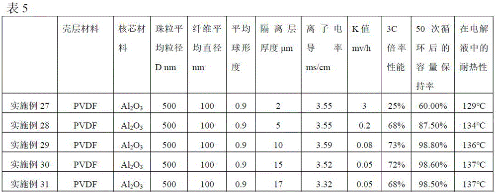
Claims (13)
1. An electrode assembly comprising an electrode sheet and an isolating layer on at least one surface of the electrode sheet, the isolating layer comprising beads and fibres between the beads, the beads comprising a shell layer and a core surrounded by the shell layer, the shell layer comprising a binder, the core comprising filler particles, the beads having an average sphericity S of not less than 0.85.
2. The electrode assembly of claim 1, wherein the average sphericity of the beads satisfies one of the following conditions:
(a)S>0.90;
(b)S>0.95。
3. the electrode assembly of claim 1, wherein the number of beads having a sphericity greater than 0.8 is 95% or more based on the total number of the beads.
4. The electrode assembly of claim 1, wherein the average particle size D of the beads satisfies one of the following conditions:
(c)100 nm≤D≤5000 nm;
(d)300 nm≤D≤1500 nm。
5. the electrode assembly of claim 1, wherein the average diameter of the core is 20nm to 4000nm and the average thickness of the shell is 20nm to 1000nm; the ratio of the average diameter of the core to the average thickness of the shell layer satisfies one of the following conditions:
(e) 1:50 to 10:1;
(f) 1:1 to 4:1.
6. The electrode assembly of claim 1, wherein the mass ratio of the shell to the fiber satisfies one of the following conditions:
(g) 1:1 to 10:1;
(h) 1:1 to 5:1.
7. The electrode assembly of claim 1, wherein the average diameter L of the fibers satisfies one of the following conditions:
(i)20 nm≤L≤1000 nm;
(j)100 nm≤L≤500 nm。
8. the electrode assembly of claim 1, wherein an area ratio of the beads and the fibers on a surface of the separator layer satisfies one of the following conditions:
(k) 4:1 to 100:1;
(l) 5:1 to 10:1.
9. The electrode assembly of claim 1, wherein a thickness T of the separator layer satisfies one of the following conditions:
(m)5μm≤T≤15μm;
(n)5μm≤T≤10μm。
10. the electrode assembly of any one of claims 1 to 9, wherein the material of the fibers or the material of the shell layer satisfies at least one of the following conditions:
the material of the fiber comprises at least one of acrylic ester polymer, polyvinylidene fluoride, styrene-acrylic ester copolymer, vinylidene fluoride-hexafluoropropylene copolymer, acrylonitrile-acrylic ester copolymer, vinyl chloride-acrylic ester copolymer or butadiene-styrene copolymer;
The material of the shell layer of (p) comprises at least one of acrylate polymer, polyvinylidene fluoride, styrene-acrylate copolymer, vinylidene fluoride-hexafluoropropylene copolymer, acrylonitrile-acrylate copolymer, vinyl chloride-acrylate copolymer or butadiene-styrene copolymer.
11. The electrode assembly of any one of claims 1 to 9, wherein the material of the filler particles comprises at least one of inorganic particles, organic particles, or MOF materials;
the inorganic particles comprise SiO 2 、Al 2 O 3 At least one of boehmite and hydroxyapatite;
the organic particles comprise at least one of polyethylene, polypropylene and polyethylene terephthalate;
the MOF material comprises ZIF-8, ZIF-67, uiO-66-NH 2 At least one of them.
12. An electrochemical device comprising the electrode assembly of any one of claims 1 to 11.
13. An electronic device comprising the electrochemical device of claim 12.
Priority Applications (1)
| Application Number | Priority Date | Filing Date | Title |
|---|---|---|---|
| CN202310361296.9A CN116093538B (en) | 2023-04-06 | 2023-04-06 | Electrode assembly, electrochemical device, and electronic device |
Applications Claiming Priority (1)
| Application Number | Priority Date | Filing Date | Title |
|---|---|---|---|
| CN202310361296.9A CN116093538B (en) | 2023-04-06 | 2023-04-06 | Electrode assembly, electrochemical device, and electronic device |
Publications (2)
| Publication Number | Publication Date |
|---|---|
| CN116093538A true CN116093538A (en) | 2023-05-09 |
| CN116093538B CN116093538B (en) | 2023-07-14 |
Family
ID=86202929
Family Applications (1)
| Application Number | Title | Priority Date | Filing Date |
|---|---|---|---|
| CN202310361296.9A Active CN116093538B (en) | 2023-04-06 | 2023-04-06 | Electrode assembly, electrochemical device, and electronic device |
Country Status (1)
| Country | Link |
|---|---|
| CN (1) | CN116093538B (en) |
Citations (4)
| Publication number | Priority date | Publication date | Assignee | Title |
|---|---|---|---|---|
| WO2018027652A1 (en) * | 2016-08-10 | 2018-02-15 | 东莞新能源科技有限公司 | Separator, preparation method and electrochemical energy storage device |
| CN108878748A (en) * | 2018-06-25 | 2018-11-23 | 宁德新能源科技有限公司 | Electrochemical appliance |
| WO2021189469A1 (en) * | 2020-03-27 | 2021-09-30 | 宁德新能源科技有限公司 | Electrochemical device |
| WO2021189459A1 (en) * | 2020-03-27 | 2021-09-30 | 宁德新能源科技有限公司 | Electrochemical device and electronic device comprising electrochemical device |
-
2023
- 2023-04-06 CN CN202310361296.9A patent/CN116093538B/en active Active
Patent Citations (7)
| Publication number | Priority date | Publication date | Assignee | Title |
|---|---|---|---|---|
| WO2018027652A1 (en) * | 2016-08-10 | 2018-02-15 | 东莞新能源科技有限公司 | Separator, preparation method and electrochemical energy storage device |
| CN108878748A (en) * | 2018-06-25 | 2018-11-23 | 宁德新能源科技有限公司 | Electrochemical appliance |
| WO2021189469A1 (en) * | 2020-03-27 | 2021-09-30 | 宁德新能源科技有限公司 | Electrochemical device |
| WO2021189459A1 (en) * | 2020-03-27 | 2021-09-30 | 宁德新能源科技有限公司 | Electrochemical device and electronic device comprising electrochemical device |
| CN115428249A (en) * | 2020-03-27 | 2022-12-02 | 宁德新能源科技有限公司 | Electrochemical device and electronic device comprising same |
| US20230025798A1 (en) * | 2020-03-27 | 2023-01-26 | Amperex Technology Limited | Electrochemical device |
| US20230038029A1 (en) * | 2020-03-27 | 2023-02-09 | Amperex Technology Limited | Electrochemical device and electronic device containing same |
Also Published As
| Publication number | Publication date |
|---|---|
| CN116093538B (en) | 2023-07-14 |
Similar Documents
| Publication | Publication Date | Title |
|---|---|---|
| WO2022204967A1 (en) | Electrochemical device and electronic device | |
| KR20230093520A (en) | Electrochemical devices, electronic devices, and methods for manufacturing electrochemical devices | |
| JP7333474B2 (en) | electrochemical and electronic devices | |
| CN113498558B (en) | Electrochemical device and electronic device | |
| CN114068910A (en) | Electrochemical device and electronic device | |
| WO2022262287A1 (en) | Electrochemical device and electronic device | |
| US20240021784A1 (en) | Electrochemical device and electronic device | |
| CN116666751A (en) | Electrolyte, electrochemical device and electronic device comprising same | |
| US20220407081A1 (en) | Electrochemical apparatus and electronic apparatus | |
| US20230261201A1 (en) | Electrochemical apparatus and electronic apparatus | |
| WO2023160182A1 (en) | Electrochemical device and electronic device | |
| CN114583098B (en) | Electrochemical device, method for manufacturing the same, and electronic device | |
| CN113078288A (en) | Electrochemical device and electronic device | |
| CN113921757B (en) | Electrochemical device and electronic device | |
| JP2023529141A (en) | Lithium secondary battery separator and lithium secondary battery having the same | |
| JP7221949B2 (en) | Positive plates, electrochemical devices and electronic devices containing positive plates | |
| US20230369556A1 (en) | Long-life secondary battery, battery module, battery pack, and power consumption apparatus | |
| CN116759646A (en) | Secondary battery and electricity utilization device | |
| CN115411222B (en) | Electrochemical device and electronic device | |
| CN116741941A (en) | Electrode assembly, electrochemical device and electricity utilization device | |
| JP2023514835A (en) | Electrode piece, electrochemical device and electronic device containing same | |
| CN110783528A (en) | Lithium battery and preparation method thereof | |
| WO2023173410A1 (en) | Electrochemical apparatus, electronic apparatus, and method for preparing negative electrode plate | |
| CN116093538B (en) | Electrode assembly, electrochemical device, and electronic device | |
| WO2023039750A1 (en) | Negative electrode composite material and use thereof |
Legal Events
| Date | Code | Title | Description |
|---|---|---|---|
| PB01 | Publication | ||
| PB01 | Publication | ||
| SE01 | Entry into force of request for substantive examination | ||
| SE01 | Entry into force of request for substantive examination | ||
| GR01 | Patent grant | ||
| GR01 | Patent grant |