CN116088783A - Method and device for determining and/or evaluating a positioning map of an image display device - Google Patents
Method and device for determining and/or evaluating a positioning map of an image display device Download PDFInfo
- Publication number
- CN116088783A CN116088783A CN202310122842.3A CN202310122842A CN116088783A CN 116088783 A CN116088783 A CN 116088783A CN 202310122842 A CN202310122842 A CN 202310122842A CN 116088783 A CN116088783 A CN 116088783A
- Authority
- CN
- China
- Prior art keywords
- map
- processing unit
- image
- images
- metric
- Prior art date
- Legal status (The legal status is an assumption and is not a legal conclusion. Google has not performed a legal analysis and makes no representation as to the accuracy of the status listed.)
- Pending
Links
Images


Classifications
-
- G—PHYSICS
- G06—COMPUTING; CALCULATING OR COUNTING
- G06F—ELECTRIC DIGITAL DATA PROCESSING
- G06F3/00—Input arrangements for transferring data to be processed into a form capable of being handled by the computer; Output arrangements for transferring data from processing unit to output unit, e.g. interface arrangements
- G06F3/01—Input arrangements or combined input and output arrangements for interaction between user and computer
- G06F3/011—Arrangements for interaction with the human body, e.g. for user immersion in virtual reality
-
- G—PHYSICS
- G06—COMPUTING; CALCULATING OR COUNTING
- G06F—ELECTRIC DIGITAL DATA PROCESSING
- G06F3/00—Input arrangements for transferring data to be processed into a form capable of being handled by the computer; Output arrangements for transferring data from processing unit to output unit, e.g. interface arrangements
- G06F3/14—Digital output to display device ; Cooperation and interconnection of the display device with other functional units
- G06F3/1407—General aspects irrespective of display type, e.g. determination of decimal point position, display with fixed or driving decimal point, suppression of non-significant zeros
-
- G—PHYSICS
- G02—OPTICS
- G02B—OPTICAL ELEMENTS, SYSTEMS OR APPARATUS
- G02B27/00—Optical systems or apparatus not provided for by any of the groups G02B1/00 - G02B26/00, G02B30/00
- G02B27/01—Head-up displays
- G02B27/017—Head mounted
-
- G—PHYSICS
- G02—OPTICS
- G02B—OPTICAL ELEMENTS, SYSTEMS OR APPARATUS
- G02B27/00—Optical systems or apparatus not provided for by any of the groups G02B1/00 - G02B26/00, G02B30/00
- G02B27/01—Head-up displays
- G02B27/017—Head mounted
- G02B27/0172—Head mounted characterised by optical features
-
- G—PHYSICS
- G06—COMPUTING; CALCULATING OR COUNTING
- G06F—ELECTRIC DIGITAL DATA PROCESSING
- G06F1/00—Details not covered by groups G06F3/00 - G06F13/00 and G06F21/00
- G06F1/16—Constructional details or arrangements
- G06F1/1613—Constructional details or arrangements for portable computers
- G06F1/163—Wearable computers, e.g. on a belt
-
- G—PHYSICS
- G06—COMPUTING; CALCULATING OR COUNTING
- G06F—ELECTRIC DIGITAL DATA PROCESSING
- G06F1/00—Details not covered by groups G06F3/00 - G06F13/00 and G06F21/00
- G06F1/16—Constructional details or arrangements
- G06F1/1613—Constructional details or arrangements for portable computers
- G06F1/1633—Constructional details or arrangements of portable computers not specific to the type of enclosures covered by groups G06F1/1615 - G06F1/1626
- G06F1/1684—Constructional details or arrangements related to integrated I/O peripherals not covered by groups G06F1/1635 - G06F1/1675
- G06F1/1686—Constructional details or arrangements related to integrated I/O peripherals not covered by groups G06F1/1635 - G06F1/1675 the I/O peripheral being an integrated camera
-
- G—PHYSICS
- G06—COMPUTING; CALCULATING OR COUNTING
- G06F—ELECTRIC DIGITAL DATA PROCESSING
- G06F1/00—Details not covered by groups G06F3/00 - G06F13/00 and G06F21/00
- G06F1/16—Constructional details or arrangements
- G06F1/1613—Constructional details or arrangements for portable computers
- G06F1/1633—Constructional details or arrangements of portable computers not specific to the type of enclosures covered by groups G06F1/1615 - G06F1/1626
- G06F1/1684—Constructional details or arrangements related to integrated I/O peripherals not covered by groups G06F1/1635 - G06F1/1675
- G06F1/1688—Constructional details or arrangements related to integrated I/O peripherals not covered by groups G06F1/1635 - G06F1/1675 the I/O peripheral being integrated loudspeakers
-
- G—PHYSICS
- G06—COMPUTING; CALCULATING OR COUNTING
- G06F—ELECTRIC DIGITAL DATA PROCESSING
- G06F1/00—Details not covered by groups G06F3/00 - G06F13/00 and G06F21/00
- G06F1/16—Constructional details or arrangements
- G06F1/1613—Constructional details or arrangements for portable computers
- G06F1/1633—Constructional details or arrangements of portable computers not specific to the type of enclosures covered by groups G06F1/1615 - G06F1/1626
- G06F1/1684—Constructional details or arrangements related to integrated I/O peripherals not covered by groups G06F1/1635 - G06F1/1675
- G06F1/1694—Constructional details or arrangements related to integrated I/O peripherals not covered by groups G06F1/1635 - G06F1/1675 the I/O peripheral being a single or a set of motion sensors for pointer control or gesture input obtained by sensing movements of the portable computer
-
- G—PHYSICS
- G06—COMPUTING; CALCULATING OR COUNTING
- G06F—ELECTRIC DIGITAL DATA PROCESSING
- G06F3/00—Input arrangements for transferring data to be processed into a form capable of being handled by the computer; Output arrangements for transferring data from processing unit to output unit, e.g. interface arrangements
- G06F3/01—Input arrangements or combined input and output arrangements for interaction between user and computer
- G06F3/011—Arrangements for interaction with the human body, e.g. for user immersion in virtual reality
- G06F3/012—Head tracking input arrangements
-
- G—PHYSICS
- G06—COMPUTING; CALCULATING OR COUNTING
- G06F—ELECTRIC DIGITAL DATA PROCESSING
- G06F3/00—Input arrangements for transferring data to be processed into a form capable of being handled by the computer; Output arrangements for transferring data from processing unit to output unit, e.g. interface arrangements
- G06F3/01—Input arrangements or combined input and output arrangements for interaction between user and computer
- G06F3/011—Arrangements for interaction with the human body, e.g. for user immersion in virtual reality
- G06F3/013—Eye tracking input arrangements
-
- G—PHYSICS
- G06—COMPUTING; CALCULATING OR COUNTING
- G06T—IMAGE DATA PROCESSING OR GENERATION, IN GENERAL
- G06T15/00—3D [Three Dimensional] image rendering
- G06T15/005—General purpose rendering architectures
-
- G—PHYSICS
- G06—COMPUTING; CALCULATING OR COUNTING
- G06T—IMAGE DATA PROCESSING OR GENERATION, IN GENERAL
- G06T19/00—Manipulating 3D models or images for computer graphics
- G06T19/006—Mixed reality
-
- G—PHYSICS
- G06—COMPUTING; CALCULATING OR COUNTING
- G06T—IMAGE DATA PROCESSING OR GENERATION, IN GENERAL
- G06T19/00—Manipulating 3D models or images for computer graphics
- G06T19/20—Editing of 3D images, e.g. changing shapes or colours, aligning objects or positioning parts
-
- G—PHYSICS
- G06—COMPUTING; CALCULATING OR COUNTING
- G06V—IMAGE OR VIDEO RECOGNITION OR UNDERSTANDING
- G06V10/00—Arrangements for image or video recognition or understanding
- G06V10/20—Image preprocessing
- G06V10/22—Image preprocessing by selection of a specific region containing or referencing a pattern; Locating or processing of specific regions to guide the detection or recognition
-
- G—PHYSICS
- G06—COMPUTING; CALCULATING OR COUNTING
- G06V—IMAGE OR VIDEO RECOGNITION OR UNDERSTANDING
- G06V10/00—Arrangements for image or video recognition or understanding
- G06V10/20—Image preprocessing
- G06V10/25—Determination of region of interest [ROI] or a volume of interest [VOI]
-
- G—PHYSICS
- G06—COMPUTING; CALCULATING OR COUNTING
- G06V—IMAGE OR VIDEO RECOGNITION OR UNDERSTANDING
- G06V20/00—Scenes; Scene-specific elements
- G06V20/20—Scenes; Scene-specific elements in augmented reality scenes
-
- G—PHYSICS
- G02—OPTICS
- G02B—OPTICAL ELEMENTS, SYSTEMS OR APPARATUS
- G02B27/00—Optical systems or apparatus not provided for by any of the groups G02B1/00 - G02B26/00, G02B30/00
- G02B27/01—Head-up displays
- G02B27/0101—Head-up displays characterised by optical features
- G02B2027/0138—Head-up displays characterised by optical features comprising image capture systems, e.g. camera
Abstract
The present application relates to methods and apparatus for determining and/or evaluating a positioning map of an image display device. An apparatus configured to be worn on a head of a user, comprising: a screen configured to present graphics to a user; a camera system configured to view an environment in which a user is located; and a processing unit configured to determine a map based at least in part on the output from the camera system, wherein the map is configured to be used by the processing unit to locate a user relative to the environment; wherein the processing unit of the apparatus is further configured to obtain a metric indicating a likelihood of successfully locating the user using the map, and wherein the processing unit is configured to obtain the metric by calculating the metric or by receiving the metric.
Description
The present application is a divisional application of application having a filing date of 2019, 7 months of 24, PCT international application No. PCT/US2019/043154, chinese national phase application No. 201980049093.8, and the name of the invention "method and apparatus for determining and/or evaluating a positioning map of an image display device".
Technical Field
The present disclosure relates to image display devices configured to be worn on the head of a user, and methods and apparatus for determining and evaluating positioning maps for such image display devices.
Background
Modern computing and display technologies have facilitated the development of "mixed reality" (MR) systems for so-called "virtual reality" (VR) or "augmented reality" (AR) experiences, in which digitally rendered images or portions thereof are presented to a user in a manner in which they appear to be real or perceivable to be real. VR scenes typically involve rendering digital or virtual image information in a manner that is opaque to actual real-world visual input. AR scenes typically involve the presentation of digital or virtual image information as an enhancement to the visualization of the real world (i.e., transparency to real world visual input) around the user. Thus, AR scenes involve rendering digital or virtual image information in a manner transparent to real world visual input.
The MR system can generate and display color data, which increases the realism of the MR scene. Many of these MR systems display color data by sequentially projecting sub-images of different (e.g., primary) colors or "fields" (e.g., red, green, and blue) corresponding to a color image in rapid succession. Projecting color sub-images at a sufficiently high rate (e.g., 60Hz, 120Hz, etc.) can deliver a smooth color MR scene in the mind of the user.
Various optical systems generate images including color images at various depths for displaying MR (VR and AR) scenes. Some such optical systems are described in U.S. utility patent application Ser. No.14/555,585 (attorney docket ML.20011.00), filed on even date 27 at 11.2014, the contents of which are expressly and fully incorporated herein by reference as if fully set forth herein.
The MR system may employ a wearable display device (e.g., a display configured to be worn on the head, a head mounted display, or smart glasses) that is at least loosely coupled to the head of the user and thereby moves as the head of the user moves. If the display system detects head movements of the user, the data being displayed may be updated (e.g., "changed (warp)") to account for changes in head pose (i.e., orientation and/or position of the user's head).
As an example, if a user wearing a display device views a virtual representation of a virtual object on a display and walks around the area where the virtual object appears, the virtual object may be rendered for each point of view, giving the user the perception that they walk around the object occupying real space. If the display device is used to present multiple virtual objects, the measurement of head pose may be used to render a scene to match the dynamically changing head pose of the user and provide increased immersion.
An AR-enabled display device (configured to be worn on the head of a user) provides simultaneous viewing of both real and virtual objects. By "optically see-through" the display, the user can see through a transparent (or semi-transparent) element in the display system to directly view light from a real object in the environment. A transparent element (commonly referred to as a "combiner") superimposes light from the display on the user's view of the real world, where the light from the display projects an image of the virtual content onto a perspective view of the real object in the environment. A camera may be mounted to the display device to capture images or video of a scene viewed by the user.
Current optical systems, such as those in MR systems, optically render virtual content. The content is "virtual" in that it does not correspond to a real physical object located at a corresponding location in space. In contrast, when the user is stimulated by a light beam directed to his eyes, virtual content exists only in the brain (e.g., optical center) of the user of the display device.
In some cases, an image display device configured to be worn on a user's head may display a virtual object with respect to a real environment and/or may allow a user to place and/or manipulate the virtual object with respect to the real environment. In this case, the image display device may be configured to position the user with respect to the real environment such that the virtual object may be correctly shifted with respect to the real environment. Methods and apparatus for determining and/or evaluating a localization map of an image display device (e.g., MR device, AR device, VR device, etc.) are disclosed herein. The positioning map is configured for positioning by the image display device for the user.
Disclosure of Invention
An apparatus configured to be worn on a head of a user, comprising: a screen configured to present graphics to a user; a camera system configured to view an environment in which a user is located; and a processing unit configured to determine a map based at least in part on the output from the camera system, wherein the map is configured to be used by the processing unit to locate a user relative to the environment; wherein the processing unit of the apparatus is further configured to determine a metric indicating a likelihood of successfully locating the user using the map.
Alternatively, the processing unit may be configured to determine the metric by calculating the metric.
Alternatively, the processing unit may be configured to determine the metric by receiving the metric.
Optionally, the processing unit is configured to determine the metric based on a common visibility of points of interest associated with different camera locations.
Optionally, the camera positions comprise a first camera position of a camera of the camera system and a second camera position of the camera system.
Optionally, the camera positions comprise a first camera position of a first camera of the camera system and a second camera position of the camera system.
Optionally, the metric indicates a number of reference points that can be used to locate the user relative to the environment.
Optionally, the metric indicates a likelihood of successfully locating the user in one or more viewing directions.
Optionally, the processing unit is configured to determine the metric based on a number of times the point of interest is detected from different camera positions.
Optionally, the processing unit is configured to determine the metric without determining any convex hull.
Optionally, the metric has a directionality-based value.
Optionally, the directionality is relative to one or more vertical axes and/or one or more horizontal axes.
Optionally, the directionality comprises a direction of rotation.
Optionally, the directionality comprises a tilt angle.
Optionally, the directionality comprises a deflection angle.
Optionally, the metric has a first value associated with the first directionality and a second value associated with the second directionality.
Optionally, the metric is a three-dimensional space for one of a plurality of cells, each of the cells representing a portion of the environment, and wherein the metric has a value based on a location within the one of the plurality of cells.
Optionally, the metric is a three-dimensional space for one of the plurality of cells, each of the cells representing a portion of the environment, wherein the metric has a first value associated with a first location within the one of the plurality of cells and a second value associated with a second location within the one of the plurality of cells.
Optionally, the metric is for one of a plurality of cells, and each of the cells represents a three-dimensional space of a portion of the environment.
Optionally, the processing unit is further configured to determine a total number of images from the camera system for one of the plurality of units.
Optionally, the total number of images is associated with a certain viewing direction for the cell.
Optionally, the total number of images is associated with a plurality of viewing directions for the cell.
Optionally, the camera system is configured to obtain a plurality of images, and wherein the processing unit is configured to determine the metric for one of the plurality of units by: identifying a subset of images belonging to the same viewing direction range; determining respective scores of images in the subset of images; and summing the scores to obtain a total score.
Optionally, the processing unit is further configured to determine the average score by dividing the total score by the number of images in the subset of images.
Optionally, the average score is a metric.
Optionally, the average score represents an average expected number of common visibility points for a viewing direction range of one of the plurality of cells.
Optionally, the processing unit is configured to determine the respective score by accessing a common visibility map associating the reference point with the plurality of images.
Optionally, the common visibility map indicates which of the reference points is visible in which of the plurality of images.
Optionally, the processing unit is configured to determine each of the respective scores by determining a number of reference points detected in corresponding ones of the images in the subset of images.
Optionally, the processing unit is further configured to determine a region score indicative of the degree of coverage of the map.
Optionally, the area score is a spatial distribution of data points based on the map.
Optionally, at least one of the cells has a coverage area of 2m by 2 m.
Optionally, at least one of the cells also has a predetermined height.
Optionally, the processing unit is configured to determine the metric by: obtaining a plurality of images from a camera system; and determining a common visibility value, wherein each of the common visibility values is indicative of a number of reference points detected in a corresponding image of the plurality of images.
Optionally, the camera system comprises a plurality of cameras.
Optionally, the plurality of images includes a first subset of images generated by the plurality of cameras when the camera system is in the first position.
Optionally, the plurality of images includes a second subset of images generated by the plurality of cameras when the camera system is in the second position.
Optionally, the plurality of cameras comprises a first forward facing camera.
Optionally, the plurality of cameras comprises a second forward facing camera.
Optionally, the plurality of cameras comprises a first lateral camera.
Optionally, the plurality of cameras comprises a second lateral camera.
Optionally, the processing unit is configured to determine a desired viewing direction of the camera system for improving the value of the metric.
Optionally, the processing unit is configured to generate a graphic based on the determined desired viewing direction, the graphic being configured to instruct the user to change the current viewing direction of the camera system to the desired viewing direction.
Optionally, the camera system is configured to obtain an image of the environment after the desired viewing direction of the camera system has been reached.
Optionally, the processing unit is configured to update the map based on the image.
Optionally, the processing unit is configured to update the metric based on the updated map.
Optionally, the processing unit is further configured to determine the metric prior to positioning the user relative to the environment using the map.
Optionally, the processing unit is configured to determine the metric before allowing the device to share the content with another device.
Optionally, the processing unit is configured to determine the metric during a mapping session in which the processing unit determines the map.
Optionally, the processing unit is configured to determine the metric retroactively by accessing a map previously determined from the non-transitory medium.
Optionally, the processing unit is configured to perform the cleansing to remove or ignore data that would otherwise provide an undesirable contribution to the map if the data were used to determine the map.
Optionally, the data comprises an image from a camera system, and wherein the processing unit is configured to perform the purging by removing or disregarding the image.
Optionally, the camera system comprises a plurality of cameras, wherein the data comprises a set of images generated by the respective camera, and wherein the processing unit is configured to perform the purging by removing or disregarding the set of images.
Optionally, the data comprises an identification of a reference point in the image from the camera system, and wherein the processing unit is configured to perform the purging by ignoring the identification of the reference point.
Optionally, the data represents rays or lines associated with the image and the reference point from the camera system, and wherein the processing unit is configured to perform the purging by ignoring rays or lines associated with the image.
Optionally, the processing unit is configured to perform the purging as part of the local optimization.
Optionally, the processing unit is configured to perform beam adjustment to adjust one or more rays associated with one or more images from the camera system, wherein the processing unit is configured to perform beam adjustment after performing purging to remove data.
Optionally, the processing unit is configured to perform the beam adjustment as part of a global optimization.
Optionally, the processing unit is configured to perform global optimization based on the image from the camera system and the three-dimensional reference point.
Optionally, the processing unit is configured to perform the global optimization also based on a relative orientation between cameras of the camera system.
Optionally, the processing unit is configured to determine a score of an image obtained from the camera system.
Optionally, the score is a constraint score.
Optionally, the score indicates how constrained the image is.
Optionally, the processing unit is configured to determine the score based on a jacobian of the reference point measurements.
Optionally, the processing unit is configured to determine the score based on the information matrix as a diagonal matrix.
Optionally, the processing unit is configured to determine the score based on a number of reference points detected in the image.
Optionally, the processing unit is configured to perform data cleansing based on the score.
Optionally, the processing unit is configured to remove constraints of the image or remove the image when performing data cleansing.
Optionally, the processing unit is configured to remove a constraint of the image or remove the image when the score is below a threshold.
Optionally, the processing unit is configured to determine the map by: determining a plurality of map segments; and connecting map segments.
Optionally, the processing unit is configured to determine the first map segment of the map segments by obtaining an image from the camera system and linking the image, wherein the image is sequentially generated by the camera system.
Optionally, the processing unit is configured to determine a respective score of the image.
Optionally, the processing unit is configured to: obtaining additional images from the camera system, determining a score for the additional images, and starting a second map segment of the map segment in response to the score for the additional images from the camera system meeting the criteria.
Optionally, the processing unit is configured to start the second map segment when the score indicates that the image has a degree of constraint below a threshold with respect to the first map segment.
Optionally, the output comprises one or more images from the camera system.
An apparatus configured to be worn on a head of a user, comprising: a screen configured to present graphics to a user; a camera system configured to view an environment in which a user is located; and a processing unit configured to determine a map based at least in part on the output from the camera system, wherein the map is configured to be used by the processing unit to locate a user relative to the environment; wherein the processing unit of the apparatus is further configured to obtain a metric indicating a likelihood of successfully locating the user using the map, and wherein the processing unit is configured to obtain the metric by calculating the metric or by receiving the metric.
An apparatus configured to be worn on a head of a user, comprising: a screen configured to present graphics to a user; a camera system configured to view an environment in which a user is located; and a processing unit configured to determine a map based at least in part on the output from the camera system, wherein the map is configured to be used by the processing unit to locate a user relative to the environment; wherein the processing unit is configured to determine a score of the image obtained from the camera system, the score indicating how constrained the image is relative to the map fragment used to form the map.
Alternatively, the processing unit may be configured to determine the score by calculating the score.
Alternatively, the processing unit may be configured to determine the score by receiving the score.
Optionally, the processing unit is configured to determine the score based on a jacobian of the reference point measurements.
Optionally, the processing unit is configured to determine the score based on the information matrix as a diagonal matrix.
Optionally, the processing unit is configured to determine the score based on a number of reference points detected in the image.
Optionally, the processing unit is configured to perform data cleansing based on the score.
Optionally, the processing unit is configured to remove constraints of the image or remove the image when performing data cleansing.
Optionally, the processing unit is configured to remove a constraint of the image or remove the image when the score is below a threshold.
Optionally, the processing unit is configured to perform the cleansing to remove or ignore data that would otherwise provide an undesirable contribution to the map if the data were used to determine the map.
Optionally, the data comprises an image from a camera system, and wherein the processing unit is configured to perform the purging by removing or disregarding the image.
Optionally, the camera system comprises a plurality of cameras, wherein the data comprises a set of images generated by the respective camera, and wherein the processing unit is configured to perform the purging by removing or disregarding the set of images.
Optionally, the data comprises an identification of a reference point in the image from the camera system, and wherein the processing unit is configured to perform the purging by ignoring the identification of the reference point.
Optionally, the data represents rays or lines associated with the image and the reference point from the camera system, and wherein the processing unit is configured to perform the purging by ignoring rays or lines associated with the image.
Optionally, the processing unit is configured to perform the purging as part of the local optimization.
Optionally, the processing unit is configured to perform a beam adjustment to adjust one or more rays associated with one or more images from the camera system, wherein the processing unit is configured to perform the beam adjustment after performing the purging, wherein the image for which the score is determined is one or more images or is different from the one or more images.
Optionally, the processing unit is configured to perform the beam adjustment as part of a global optimization.
Optionally, the processing unit is configured to perform global optimization based on one or more images from the camera system and the three-dimensional reference point.
Optionally, the processing unit is configured to perform the global optimization also based on a relative orientation between cameras of the camera system.
Optionally, the processing unit is configured to determine the map by: determining a plurality of map segments, wherein the plurality of map segments includes a map segment; connecting map segments; wherein the portion of the map comprises one of the map segments.
Optionally, the camera system is configured to provide additional images, which additional images are generated by the camera system before the image for which the score is determined is generated, wherein the processing unit is configured to determine the first map segment of the map segments by linking the additional images, and wherein the additional images are generated sequentially by the camera system.
Optionally, the processing unit is configured to determine a respective score of the additional image.
Optionally, the processing unit is configured to start a second map segment of the map segments in response to the score of the image from the camera system meeting a criterion.
Optionally, the processing unit is configured to start the second map segment when the score indicates that the image has a degree of constraint below a threshold with respect to the first map segment.
Optionally, the processing unit of the apparatus is further configured to determine a metric indicating a likelihood of successfully locating the user using the map.
Optionally, the processing unit is configured to determine the metric based on a common visibility of points of interest associated with different camera locations.
Optionally, the camera positions comprise a first camera position of a camera of the camera system and a second camera position of the camera system.
Optionally, the camera positions comprise a first camera position of a first camera of the camera system and a second camera position of the camera system.
Optionally, the metric indicates a number of reference points that can be used to locate the user relative to the environment.
Optionally, the metric indicates a likelihood of successfully locating the user in one or more viewing directions.
Optionally, the processing unit is configured to determine the metric based on a number of times the point of interest is detected from different camera positions.
Optionally, the processing unit is configured to determine the metric without determining any convex hull.
Optionally, the metric has a directionality-based value.
Optionally, the directionality is relative to one or more vertical axes and/or one or more horizontal axes.
Optionally, the directionality comprises a direction of rotation.
Optionally, the directionality comprises a tilt angle.
Optionally, the directionality comprises a deflection angle.
Optionally, the metric has a first value associated with the first directionality and a second value associated with the second directionality.
Optionally, the metric is a three-dimensional space for one of a plurality of cells, each of the cells representing a portion of the environment, and wherein the metric has a value based on a location within the one of the plurality of cells.
Optionally, the metric is a three-dimensional space for one of the plurality of cells, each of the cells representing a portion of the environment, wherein the metric has a first value associated with a first location within the one of the plurality of cells and a second value associated with a second location within the one of the plurality of cells.
Optionally, the metric is for one of a plurality of cells, and each of the cells represents a three-dimensional space of a portion of the environment.
Optionally, the processing unit is further configured to determine a total number of images from the camera system for one of the plurality of units.
Optionally, the total number of images is associated with a certain viewing direction for the cell.
Optionally, the total number of images is associated with a plurality of viewing directions for the cell.
Optionally, the camera system is configured to obtain a plurality of images including the image for which the score is determined, and wherein the processing unit is configured to determine the metric for one of the plurality of units by: identifying a subset of images belonging to the same viewing direction range; determining respective scores of images in the subset of images; and summing the scores to obtain a total score.
Optionally, the processing unit is further configured to determine the average score by dividing the total score by the number of images in the subset of images.
Optionally, the average score is a metric.
Optionally, the average score represents an average expected number of common visibility points for a viewing direction range of one of the plurality of cells.
Optionally, the processing unit is configured to determine the respective score by accessing a common visibility map associating the reference point with the plurality of images.
Optionally, the common visibility map indicates which of the reference points is visible in which of the plurality of images.
Optionally, the processing unit is configured to determine each of the respective scores by determining a number of reference points detected in corresponding ones of the images in the subset of images.
Optionally, the processing unit is further configured to determine a region score indicative of the degree of coverage of the map.
Optionally, the area score is a spatial distribution of data points based on the map.
Optionally, at least one of the cells has a coverage area of 2m by 2 m.
Optionally, at least one of the cells also has a predetermined height.
Optionally, the processing unit is configured to determine the metric by: obtaining a plurality of images from a camera system, the plurality of images including an image for which a score is determined; and determining a common visibility value, wherein each of the common visibility values is indicative of a number of reference points detected in a corresponding image of the plurality of images.
Optionally, the camera system comprises a plurality of cameras.
Optionally, the plurality of images includes a first subset of images generated by the plurality of cameras when the camera system is in the first position.
Optionally, the plurality of images includes a second subset of images generated by the plurality of cameras when the camera system is in the second position.
Optionally, the plurality of cameras comprises a first forward facing camera.
Optionally, the plurality of cameras comprises a second forward facing camera.
Optionally, the plurality of cameras comprises a first lateral camera.
Optionally, the plurality of cameras comprises a second lateral camera.
Optionally, the processing unit is configured to determine a desired viewing direction of the camera system for improving the value of the metric.
Optionally, the processing unit is configured to generate a graphic based on the determined desired viewing direction, the graphic being configured to instruct the user to change the current viewing direction of the camera system to the desired viewing direction.
Optionally, the camera system is configured to obtain the additional image after the desired viewing direction of the camera system has been reached.
Optionally, the processing unit is configured to update the map based on the additional image.
Optionally, the processing unit is configured to update the metric based on the updated map.
Optionally, the processing unit is further configured to determine the metric prior to positioning the user relative to the environment using the map.
Optionally, the processing unit is configured to determine the metric before allowing the device to share the content with another device.
Optionally, the processing unit is configured to determine the metric during a mapping session in which the processing unit determines the map.
Optionally, the processing unit is configured to determine the metric retroactively by accessing a map previously determined from the non-transitory medium.
An apparatus configured to be worn on a head of a user, comprising: a screen configured to present graphics to a user; a camera system configured to view an environment in which a user is located; and a processing unit configured to determine a map based at least in part on the output from the camera system, wherein the map is configured to be used by the processing unit to locate a user relative to the environment; wherein the processing unit is configured to determine a score of the image obtained from the camera system, the score indicating how constrained the image is relative to the map segments used to form the map, and wherein the processing unit is configured to obtain the score by calculating the score or by receiving the score.
A method performed by an apparatus configured to be worn on a head of a user, the apparatus having a screen configured to present graphics to the user, a camera system configured to view an environment in which the user is located, and a processing unit, the method comprising: obtaining, by a processing unit, an output from the camera system; determining, by the processing unit, a map based at least in part on the output from the camera system, wherein the map is configured to be used by the processing unit to locate a user relative to the environment; and obtaining, by the processing unit, a metric indicating a likelihood of successfully locating the user using the map.
Optionally, the act of determining the metric comprises calculating the metric.
Optionally, the act of determining the metric comprises receiving the metric.
Optionally, the metric is determined based on a common visibility of points of interest associated with different camera locations.
Optionally, the camera positions comprise a first camera position of a camera of the camera system and a second camera position of the camera system.
Optionally, the camera positions comprise a first camera position of a first camera of the camera system and a second camera position of the camera system.
Optionally, the metric indicates a number of reference points that can be used to locate the user relative to the environment.
Optionally, the metric indicates a likelihood of successfully locating the user in one or more viewing directions.
Optionally, the metric is determined based on the number of times the point of interest is detected from different camera positions.
Optionally, the metric is determined by the processing unit without determining any convex hull.
Optionally, the metric has a directionality-based value.
Optionally, the directionality is relative to one or more vertical axes and/or one or more horizontal axes.
Optionally, the directionality comprises a direction of rotation.
Optionally, the directionality comprises a tilt angle.
Optionally, the directionality comprises a deflection angle.
Optionally, the metric has a first value associated with the first directionality and a second value associated with the second directionality.
Optionally, the metric is a three-dimensional space for one of a plurality of cells, each of the cells representing a portion of the environment, and wherein the metric has a value based on a location within the one of the plurality of cells.
Optionally, the metric is a three-dimensional space for one of the plurality of cells, each of the cells representing a portion of the environment, wherein the metric has a first value associated with a first location within the one of the plurality of cells and a second value associated with a second location within the one of the plurality of cells.
Optionally, the metric is for one of a plurality of cells, and each of the cells represents a three-dimensional space of a portion of the environment.
Optionally, the act of determining the metric comprises determining a total number of images from the camera system associated with one of the plurality of units.
Optionally, the total number of images is associated with a certain viewing direction for the cell.
Optionally, the total number of images is associated with a plurality of viewing directions for the cell.
Optionally, the camera system is configured to obtain a plurality of images, and wherein the metric is determined for one of the plurality of units by: identifying a subset of images belonging to the same viewing direction range; determining respective scores of images in the subset of images; and summing the scores to obtain a total score.
Optionally, the metric is determined by dividing the total score by the number of images in the subset of images to obtain an average score.
Optionally, the average score is a metric.
Optionally, the average score represents an average expected number of common visibility points for a viewing direction range of one of the plurality of cells.
Optionally, the respective scores are determined by accessing a common visibility map that associates the reference points with the plurality of images.
Optionally, the common visibility map indicates which of the reference points is visible in which of the plurality of images.
Optionally, each of the respective scores is determined by determining a number of reference points detected in a corresponding one of the images in the subset of images.
Optionally, the method further comprises determining a region score indicative of the degree of coverage of the map.
Optionally, the area score is determined based on a spatial distribution of data points of the map.
Optionally, at least one of the cells has a coverage area of 2m by 2 m.
Optionally, at least one of the cells also has a predetermined height.
Optionally, the metric is determined by: obtaining a plurality of images from a camera system; and determining a common visibility value, wherein each of the common visibility values is indicative of a number of reference points detected in a corresponding image of the plurality of images.
Optionally, the camera system comprises a plurality of cameras.
Optionally, the plurality of images includes a first subset of images generated by the plurality of cameras when the camera system is in the first position.
Optionally, the plurality of images includes a second subset of images generated by the plurality of cameras when the camera system is in the second position.
Optionally, the plurality of cameras comprises a first forward facing camera.
Optionally, the plurality of cameras comprises a second forward facing camera.
Optionally, the plurality of cameras comprises a first lateral camera.
Optionally, the plurality of cameras comprises a second lateral camera.
Optionally, the method further comprises determining, by the processing unit, a desired viewing direction of the camera system for improving the value of the metric.
Optionally, the method further comprises generating a graphic based on the determined desired viewing direction, the graphic being configured to instruct the user to change the current viewing direction of the camera system to the desired viewing direction.
Optionally, the method further comprises obtaining an image of the environment from the camera system after the desired viewing direction of the camera system has been reached.
Optionally, the method further comprises updating the map based on the image.
Optionally, the method further comprises updating the metric based on the updated map.
Optionally, the metrics are determined before the map is used to locate the user relative to the environment.
Optionally, the metrics are determined before the device shares the content with another device.
Optionally, the metrics are determined during a mapping session in which the processing unit determines the map.
Alternatively, the metrics are determined retroactively by accessing a map previously determined from a non-transitory medium.
Optionally, the method further comprises performing a purge to remove or ignore data that would otherwise provide an undesirable contribution to the map if the data were used to determine the map.
Optionally, the data comprises an image from a camera system, and wherein the purging is performed by removing or ignoring the image.
Optionally, the camera system comprises a plurality of cameras, wherein the data comprises a set of images generated by the respective camera, and wherein the purging is performed by removing or disregarding the set of images.
Optionally, the data comprises an identification of a reference point in the image from the camera system, and wherein the purging is performed by ignoring the identification of the reference point.
Optionally, the data represents rays or lines associated with the image and the reference point from the camera system, and wherein the purging is performed by ignoring the rays or lines associated with the image.
Optionally, purging is performed as part of the local optimization.
Optionally, the method further comprises performing a beam adjustment to adjust one or more rays associated with one or more images from the camera system, wherein the beam adjustment is performed after performing the purging to remove the data.
Optionally, the beam adjustment is performed as part of a global optimization.
Optionally, a global optimization is performed based on the images from the camera system and the three-dimensional reference point.
Optionally, global optimization is also performed based on the relative orientation between the cameras of the camera system.
Optionally, the method further comprises determining, by the processing unit, a score of the image obtained from the camera system.
Optionally, the score is a constraint score.
Optionally, the score indicates how constrained the image is.
Optionally, the score is determined based on a jacobian of the reference point measurements.
Alternatively, the score is determined based on the information matrix as a diagonal matrix.
Optionally, the score is determined based on the number of reference points detected in the image.
Optionally, the method further comprises performing data cleansing based on the score.
Optionally, the act of performing data cleansing includes removing a constraint of the image or removing the image.
Optionally, when the score is below a threshold, removing the constraint of the image or removing the image.
Optionally, the map is determined by: determining a plurality of map segments; and connecting map segments.
Optionally, the act of determining the plurality of map segments comprises determining a first map segment of the map segments by obtaining an image from the camera system and linking the image, wherein the image is sequentially generated by the camera system.
Optionally, the method further comprises determining a respective score of the image.
Optionally, the method further comprises: obtaining additional images from the camera system, determining a score for the additional images, and starting a second map segment of the map segment in response to the score for the additional images from the camera system meeting the criteria.
Optionally, the second map segment is started when the score indicates that the image has a degree of constraint below a threshold value relative to the first map segment.
Optionally, the output comprises one or more images from the camera system.
A method performed by an apparatus configured to be worn on a head of a user, the apparatus having a screen configured to present graphics to the user, a camera system configured to view an environment in which the user is located, and a processing unit, the method comprising: obtaining, by a processing unit, an output from the camera system; determining, by the processing unit, a map based at least in part on the output from the camera system, wherein the map is configured to be used by the processing unit to locate a user relative to the environment; and obtaining, by the processing unit, a metric indicating a likelihood of successfully locating the user using the map, wherein the act of obtaining comprises calculating, by the processing unit, the metric or receiving the metric.
A method performed by an apparatus configured to be worn on a head of a user, the apparatus having a screen configured to present graphics to the user, a camera system configured to view an environment in which the user is located, and a processing unit, the method comprising: obtaining, by a processing unit, an output from the camera system; determining, by the processing unit, a map based at least in part on the output from the camera system, wherein the map is configured to be used by the processing unit to locate a user relative to the environment; and obtaining, by the processing unit, a score of the image obtained from the camera system, the score indicating how constrained the image is relative to the map segment used to form the map.
Optionally, the act of determining the score comprises calculating the score.
Optionally, the act of determining the score comprises receiving the score.
Optionally, the score is determined based on a jacobian of the reference point measurements.
Alternatively, the score is determined based on the information matrix as a diagonal matrix.
Optionally, the score is determined based on the number of reference points detected in the image.
Optionally, the method further comprises performing, by the processing unit, data cleansing based on the score.
Optionally, the act of performing data cleansing includes removing a constraint of the image or removing the image.
Optionally, the act of performing data cleansing includes removing a constraint of the image or removing the image when the score is below a threshold.
Optionally, purging is performed to remove or ignore data that would otherwise provide an undesirable contribution to the map if the data were used to determine the map.
Optionally, the data comprises an image from a camera system, and wherein the purging is performed to remove or ignore the image.
Optionally, the camera system comprises a plurality of cameras, wherein the data comprises a set of images generated by the respective camera, and wherein the purging is performed to remove or ignore the set of images.
Optionally, the data comprises an identification of a reference point in the image from the camera system, and wherein the purging is performed to ignore the identification of the reference point.
Optionally, the data represents rays or lines associated with the image and the reference point from the camera system, and wherein the purging is performed to ignore rays or lines associated with the image.
Optionally, purging is performed as part of the local optimization.
Optionally, the method further comprises performing a beam adjustment to adjust one or more rays associated with one or more images from the camera system, wherein the beam adjustment is performed after performing the purging, wherein the determined score image is one of the one or more images, or is different from the one or more images.
Optionally, the beam adjustment is performed as part of a global optimization.
Optionally, the method further comprises performing, by the processing unit, global optimization based on the one or more images from the camera system and the three-dimensional reference point.
Optionally, global optimization is also performed based on the relative orientation between the cameras of the camera system.
Optionally, the map is determined by: determining a plurality of map segments, wherein the plurality of map segments includes a map segment; connecting map segments; wherein the portion of the map includes one of the map segments.
Optionally, the camera system is configured to provide additional images, the additional images being generated by the camera system before the images of the determined score are generated, wherein the act of determining the map comprises determining a first map segment of the map segment by linking the additional images, and wherein the additional images are generated sequentially by the camera system.
Optionally, the method further comprises determining a respective score of the additional image.
Optionally, the method further comprises starting, by the processing unit, a second map segment of the map segments in response to the score of the image from the camera system meeting the criterion.
Optionally, the second map segment is started when the score indicates that the image has a degree of constraint below a threshold value relative to the first map segment.
Optionally, the method further comprises determining a metric indicating a likelihood of successfully locating the user using the map.
Optionally, the metric is determined based on a common visibility of points of interest associated with different camera locations.
Optionally, the camera positions comprise a first camera position of a camera of the camera system and a second camera position of the camera system.
Optionally, the camera positions comprise a first camera position of a first camera of the camera system and a second camera position of the camera system.
Optionally, the metric indicates a number of reference points that can be used to locate the user relative to the environment.
Optionally, the metric indicates a likelihood of successfully locating the user in one or more viewing directions.
Optionally, the metric is determined based on the number of times the point of interest is detected from different camera positions.
Optionally, the metric is determined by the processing unit without determining any convex hull.
Optionally, the metric has a directionality-based value.
Optionally, the directionality is relative to one or more vertical axes and/or one or more horizontal axes.
Optionally, the directionality comprises a direction of rotation.
Optionally, the directionality comprises a tilt angle.
Optionally, the directionality comprises a deflection angle.
Optionally, the metric has a first value associated with the first directionality and a second value associated with the second directionality.
Optionally, the metric is a three-dimensional space for one of a plurality of cells, each of the cells representing a portion of the environment, and wherein the metric has a value based on a location within the one of the plurality of cells.
Optionally, the metric is a three-dimensional space for one of the plurality of cells, each of the cells representing a portion of the environment, wherein the metric has a first value associated with a first location within the one of the plurality of cells and a second value associated with a second location within the one of the plurality of cells.
Optionally, the metric is for one of a plurality of cells, and each of the cells represents a three-dimensional space of a portion of the environment.
Optionally, the act of determining the metric comprises determining a total number of images from the camera system associated with one of the plurality of units.
Optionally, the total number of images is associated with a certain viewing direction of the application unit.
Optionally, the total number of images is associated with a plurality of viewing directions of the application unit.
Optionally, the camera system is configured to obtain a plurality of images including the determined score image, and wherein the metric is determined for one of the plurality of units by: identifying a subset of images belonging to the same viewing direction range; determining respective scores of images in the subset of images; and summing the scores to obtain a total score.
Optionally, the method further comprises dividing the total score by the number of images in the subset of images to obtain an average score.
Optionally, the average score is a metric.
Optionally, the average score represents an average expected number of common visibility points for a viewing direction range of one of the plurality of cells.
Optionally, the respective scores are determined by accessing a common visibility map that associates the reference points with the plurality of images.
Optionally, the common visibility map indicates which of the reference points is visible in which of the plurality of images.
Optionally, each of the respective scores is determined by determining a number of reference points detected in a corresponding one of the images in the subset of images.
Optionally, the method further comprises determining a region score indicative of the degree of coverage of the map.
Optionally, the area score is a spatial distribution of data points based on the map.
Optionally, at least one of the cells has a coverage area of 2m by 2 m.
Optionally, at least one of the cells also has a predetermined height.
Optionally, the metric is determined by: obtaining a plurality of images from a camera system, the plurality of images including the determined score of the image; and determining a common visibility value, wherein each of the common visibility values is indicative of a number of reference points detected in a corresponding image of the plurality of images.
Optionally, the camera system comprises a plurality of cameras.
Optionally, the plurality of images includes a first subset of images generated by the plurality of cameras when the camera system is in the first position.
Optionally, the plurality of images includes a second subset of images generated by the plurality of cameras when the camera system is in the second position.
Optionally, the plurality of cameras comprises a first forward facing camera.
Optionally, the plurality of cameras comprises a second forward facing camera.
Optionally, the plurality of cameras comprises a first lateral camera.
Optionally, the plurality of cameras comprises a second lateral camera.
Optionally, the method further comprises determining, by the processing unit, a desired viewing direction of the camera system for improving the value of the metric.
Optionally, the method further comprises generating a graphic based on the determined desired viewing direction, the graphic being configured to instruct the user to change the current viewing direction of the camera system to the desired viewing direction.
Optionally, the method further comprises obtaining additional images from the camera system after the desired viewing direction of the camera system has been reached.
Optionally, the method further comprises updating the map based on the additional image.
Optionally, the method further comprises updating the metric based on the updated map.
Optionally, the metrics are determined before the processing unit locates the user relative to the environment using the map.
Optionally, the metrics are determined before the device shares the content with another device.
Optionally, the metrics are determined during a mapping session in which the processing unit determines the map.
Alternatively, the metrics are determined retroactively by accessing a map previously determined from a non-transitory medium.
A method performed by an apparatus configured to be worn on a head of a user, the apparatus having a screen configured to present graphics to the user, a camera system configured to view an environment in which the user is located, and a processing unit, the method comprising: obtaining, by a processing unit, an output from the camera system; determining, by the processing unit, a map based at least in part on the output from the camera system, wherein the map is configured to be used by the processing unit to locate a user relative to the environment; and obtaining, by the processing unit, a score for the image obtained from the camera system, the score indicating how constrained the image is relative to the map segments used to form the map, wherein the act of obtaining the score comprises calculating, by the processing unit, the score or receiving the score.
Additional and other objects, features, and advantages of the disclosure are described in the detailed description, drawings, and claims.
Drawings
The drawings illustrate the design and utility of various embodiments of the present disclosure. It should be noted that the drawings are not drawn to scale and that elements having similar structures or functions are represented by like reference numerals throughout the drawings. In order to better understand how the above and other advantages and objects of the various embodiments of the disclosure are obtained, a more detailed description of the disclosure briefly described above will be presented by reference to a particular embodiment of the disclosure. Understanding that these drawings depict only typical embodiments of the disclosure and are not therefore to be considered to be limiting of its scope, the disclosure will be described and explained with additional specificity and detail through the use of the accompanying drawings in which:
fig. 1 illustrates another image display system having an image display device according to some embodiments.
Fig. 2 illustrates another image display system having an image display device according to other embodiments.
Fig. 3 illustrates another image display system having an image display device according to other embodiments.
Fig. 4 illustrates another image display system having an image display device according to other embodiments.
Fig. 5 shows an image display apparatus displaying frames at a plurality of depth planes.
Fig. 6 illustrates a method for determining a map for allowing an image display device to locate a user of the image display device and/or perform other functions.
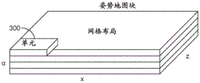
Fig. 7 shows an example of an environment divided into a plurality of units.
Fig. 8A illustrates a method of determining a metric that indicates a likelihood of successfully locating a user using a map.
Fig. 8B shows a graphical representation of the method of fig. 8A.
Fig. 9 shows an example of a common visibility graph.
Fig. 10 illustrates a map and positioning management method.
Fig. 11 illustrates a method of sharing content between users of an image display apparatus.
Fig. 12 illustrates a technique for determining a map that allows an image display device to locate a user of the image display device and/or perform other functions.
Fig. 13 illustrates a method for determining a map that allows an image display device to locate a user of the image display device and/or perform other functions.
Fig. 14 illustrates a method performed by an image display device according to some embodiments.
Fig. 15 illustrates another method performed by an image display device according to some embodiments.
Fig. 16 illustrates a special purpose processing system in accordance with some embodiments.
Detailed Description
Various embodiments of the present disclosure relate to methods, apparatuses, and articles of manufacture for providing input to a video image device configured to be worn on a user's head. Other objects, features, and advantages of the present disclosure are described in the detailed description, drawings, and claims.
Various embodiments are described hereinafter with reference to the accompanying drawings. It should be noted that the drawings are not drawn to scale and that elements having similar structures or functions are represented by like reference numerals throughout the drawings. It should also be noted that the drawings are only intended to facilitate the description of the embodiments. They are not intended as an exhaustive description of the invention or as a limitation on the scope of the invention. In addition, the illustrated embodiments need not have all of the aspects or advantages shown. Aspects or advantages described in connection with a particular embodiment are not necessarily limited to that embodiment and may be practiced in any other embodiment even if not shown or if not explicitly described.
The following description relates to exemplary VR, AR, and/or MR systems that may practice the embodiments described herein. However, it should be understood that embodiments are also applicable to applications in other types of display systems (including other types of VR, AR, and/or MR systems), and thus embodiments are not limited to only the illustrative examples disclosed herein.
Overview of problems and solutions
In some cases, in order to locate a user of the image display apparatus with respect to the environment of the user, a location map of the environment is obtained. The real-time tracking image from the camera system of the image display device is then matched with the positioning map to locate the user. The success of positioning depends on the quality of the positioning map. It would therefore be advantageous to determine a metric for indicating the quality of a map, the metric indicating the likelihood of success of locating using the map. Various techniques may be employed to determine the metrics. In one implementation, the metric is determined based on a common visibility of reference points captured in different images. The reference points may be map points representing features of interest (such as corners, edges, etc.), which may be used to identify objects in the environment for positioning purposes. After the user may be successfully located with respect to the user's environment, the user may then use the image display device to place virtual content with respect to the environment, retrieve previous content from previous sessions, share content in the environment with other users, and so forth.
The positioning map may be created using a camera system of the image display device. Specifically, a user of the image display device performs different head gestures (e.g., turns the head) to "scan" the environment. In so doing, the camera system captures an image of the environment. Then, the processing unit of the image display apparatus processes the image to create a map. In some embodiments, to improve the quality of the map, undesirable data that may contribute to the map may be removed and/or adjusted during the map creation process.
In one example, the undesirable data may be images that are not well constrained with respect to the map segment. When images are generated in sequence for creating a map, the images are linked together to form a map fragment. Each image may capture a certain number of reference points (e.g., map points). If an image has captured many reference points that are also captured by other images, the image may be considered well constrained with respect to the fragment being created. On the other hand, if an image has only a few reference points, and/or reference points in the image are not detected by other images, the image may be considered to be poorly constrained with respect to the fragment being created. In some embodiments, images that are not well-constrained may be removed, and map segments with well-constrained images may be connected together to form a positioning map.
Fig. 1-4 illustrate various components of an image display system 100 in various embodiments. The image display system 100 comprises an image display device 101 and means 200 for providing an input to the image display device 101. The apparatus 200 will be described in more detail below. The image display device 101 may be any of a VR device, an AR device, an MR device, or other type of display device. The image display device 101 includes a frame structure 102 worn by the end user 50, a display subsystem 110 carried by the frame structure 102 such that the display subsystem 110 is positioned in front of the eyes of the end user 50, and a speaker 106 carried by the frame structure 102 such that the speaker 106 is positioned adjacent to an ear canal of the end user 50 (optionally, another speaker (not shown) is positioned adjacent to another ear canal of the end user 50 to provide stereo/shapeable sound control). The display subsystem 110 is designed to present to the eyes of the end user 50 an enhanced light pattern that can be comfortably perceived as physical reality with a high level of image quality and three-dimensional perception and to be able to present two-dimensional content. The display subsystem 110 presents the sequence of frames at a high frequency that provides perception of a single coherent scene.
In the illustrated embodiment, the display subsystem 110 employs an "optical see-through" display by which a user can directly view light from a real object via a transparent (or semi-transparent) element. A transparent element, commonly referred to as a "combiner", superimposes light from the display on the user's view of the real world. To this end, display subsystem 110 includes a partially transparent display. The display is positioned in the end user's 50 field of view between the end user's 50 eyes and the surrounding environment such that direct light from the surrounding environment is transmitted through the display to the end user's 50 eyes.
In the illustrated embodiment, the image projection assembly provides light to a partially transparent display, so as to combine with direct light from the surrounding environment, and is transmitted from the display to the eyes of the user 50. The projection subsystem may be a fiber-scan based projection device and the display may be a waveguide-based display into which the scanning light from the projection subsystem is injected to produce, for example, images at a single optical viewing distance closer than infinity (e.g., the length of an arm), images at a plurality of discrete optical viewing distances or focal planes, and/or image layers stacked at a plurality of viewing distances or focal planes to represent a volumetric 3D object. The layers in the light field may be stacked close enough together to appear continuous with the human visual subsystem (i.e., one layer is within the cone of confusion (cone of confusion) of an adjacent layer). Additionally or alternatively, even if the layers are stacked more sparsely (i.e., one layer is outside the confusion cone of an adjacent layer), image elements may be mixed across two or more layers to increase the perceived continuity of the transition between layers in the light field. The display subsystem 110 may be monocular or binocular.
The image display device 101 may also include one or more sensors (not shown) mounted to the frame structure 102 for detecting the position and movement of the head 54 of the end user 50 and/or the eye position and interocular distance of the end user 50. Such sensors may include image capturing devices (such as cameras), microphones, inertial measurement units, accelerometers, compasses, GPS units, radios and/or gyroscopes) or any combination of the foregoing. Many of these sensors operate based on the assumption that the frame 102 to which they are secured is in turn substantially secured to the user's head, eyes and ears.
The image display device 101 may further include a user orientation detection module. The user orientation module detects the instantaneous position of the head 54 of the end user 50 (e.g., via a sensor coupled to the frame 102) and may predict the position of the head 54 of the end user 50 based on position data received from the sensor. Detecting the instantaneous position of the head 54 of the end user 50 helps to determine the particular actual object that the end user 50 is looking at, thereby providing an indication of the particular virtual object that the actual object is to generate, and further providing an indication of the location at which the virtual object is to be displayed. The user orientation module may also track the eyes of the end user 50 based on tracking data received from the sensors.
The image display device 101 may also include a control subsystem that may take any of a variety of forms. The control subsystem includes a plurality of controllers, such as one or more microcontrollers, microprocessors or Central Processing Units (CPUs), digital signal processors, graphics Processing Units (GPUs), other integrated circuit controllers, such as Application Specific Integrated Circuits (ASICs), programmable Gate Arrays (PGAs) (e.g., field PGAs (FPGAs)), and/or programmable logic controllers (PLUs).
The control subsystem of the image display device 101 may include a Central Processing Unit (CPU), a Graphics Processing Unit (GPU), one or more frame buffers, and a three-dimensional database for storing three-dimensional scene data. The CPU may control overall operation, while the GPU may render frames from three-dimensional data stored in a three-dimensional database (i.e., convert a three-dimensional scene into a two-dimensional image) and store the frames in a frame buffer. One or more additional integrated circuits may control the reading and/or readout of frames from the frame buffer and control the operation of the image projection components of display subsystem 110.
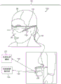
The various processing components of the image display device 101 may be physically contained in a distributed subsystem. For example, as shown in fig. 1-4, image display device 101 includes a local processing and data module 130, which local processing and data module 130 is operably coupled (e.g., via a wired lead or wireless connection 136) to display subsystem 110 and sensors. The local processing and data module 130 may be mounted in various configurations, such as fixedly attached to the frame structure 102 (fig. 1), fixedly attached to the helmet or hat 56 (fig. 2), removably attached to the torso 58 (fig. 3) of the end user 50, or removably attached to the hip 60 (fig. 4) of the end user 50 in a band-coupled configuration. The image display device 101 also includes a remote processing module 132 and a remote data repository 134 operatively coupled (e.g., via wired or wireless connections 138, 140) to the local processing and data module 130 such that these remote modules 132, 134 are operatively coupled to each other and can serve as a source of the local processing and data module 130.
The local processing and data module 130 may include a power efficient processor or controller and a digital memory such as flash memory, both of which may be used to facilitate processing, caching and storing data captured from the sensors and/or retrieving and/or processing data using the remote processing module 132 and/or the remote data repository 134, which may be transferred to the display subsystem 110 after such processing or retrieval. Remote processing module 132 may include one or more relatively powerful processors or controllers configured to analyze and process data and/or image information. The remote data repository 134 may include a relatively large-scale digital data storage facility that is available through the internet or other network configuration in a "cloud" resource configuration. In some embodiments, all data is stored and all calculations are performed in the local processing and data module 130, allowing fully autonomous use from any remote module.
The couplings 136, 138, 140 between the various components described above may include one or more wired interfaces or ports for providing wired or optical communications or one or more wireless interfaces or ports for providing wireless communications, such as through RF, microwave, and IR. In some implementations, all communications may be wired, while in other implementations, all communications may be wireless. In still further implementations, the selection of wired and wireless communications may be different than those shown in FIGS. 1-4. Accordingly, the particular choice of wired or wireless communication should not be considered limiting.
In some embodiments, the user orientation module is contained in the local processing and data module 130, while the CPU and GPU are contained in the remote processing module. In alternative embodiments, the CPU, GPU, or portion thereof may be included in the local processing and data module 130. The 3D database may be associated with the remote data repository 134 or may be locally located.
Some image display systems (e.g., VR systems, AR systems, MR systems, etc.) use multiple volume phase holograms, surface relief holograms, or photoconductive optical elements embedded with depth plane information to generate images that appear to come from various depth planes. In other words, a diffraction pattern or diffractive optical element ("DOE") may be embedded within a light guide optical element ("LOE"; e.g., a planar waveguide) or embossed/engraved (emboss) on the LOE such that collimated light (a beam of light having a substantially planar wavefront) is substantially totally internally reflected along the LOE, intersecting the diffraction pattern at a plurality of locations and exiting toward the user's eye. The DOE is configured such that light exiting the LOE therethrough converges such that they appear to originate from a particular depth plane. An optical condenser lens ("condenser") may be used to generate the collimated light.
For example, the first LOE may be configured to transmit collimated light to the eye that appears to originate from an optical infinity depth plane (0 diopters). Another LOE may be configured to transmit collimated light that appears to originate from a distance of 2 meters (1/2 diopters). Yet another LOE may be configured to transmit collimated light that appears to originate from a distance of 1 meter (1 diopter). By using stacked LOE assemblies, it can be appreciated that multiple depth planes can be formed, with each LOE configured to display images that appear to originate from a particular depth plane. It should be appreciated that the stack may include any number of LOEs. However, at least N stacked LOEs are required to generate N depth planes. Furthermore, an RGB color image may be generated on N depth planes using N, 2N, or 3N stacked LOEs.
To present 3D virtual content to a user, the image display system 100 (e.g., VR system, AR system, MR system, etc.) projects images of the virtual content into the user's eyes such that the images appear to originate from respective depth planes in the Z-direction (i.e., orthogonally away from the user's eyes). In other words, the virtual content may not only change in the X and Y directions (i.e., in a 2D plane orthogonal to the central visual axis of the user's eye), but may also appear to change in the Z direction so that the user may perceive that the object is very close to or at infinity or any distance in between. In other embodiments, the user may perceive multiple objects at different depth planes simultaneously. For example, the user may see that the virtual dragon appears to be running from infinity to the user. Alternatively, the user may simultaneously see a virtual bird at a distance of 3 meters from the user and a virtual coffee cup at an arm length (about 1 meter) from the user.
The multi-plane focusing system forms a variable depth perception by projecting an image on some or all of a plurality of depth planes at respective fixed distances from the user's eyes in the Z-direction. Referring now to fig. 5, it should be appreciated that the multi-plane focusing system may display frames at a fixed depth plane 150 (e.g., six depth planes 150 shown in fig. 5). Although the MR system may include any number of depth planes 150, one exemplary multi-plane focusing system has six fixed depth planes 150 in the Z-direction. When virtual content is generated at one or more of the six depth planes 150, a 3D perception is formed such that the user perceives one or more virtual objects at different distances from the user's eyes. It is assumed that the human eye is more sensitive to objects closer to the eye than objects that appear farther away, thus generating more depth planes 150 closer to the eye, as shown in fig. 5. In other embodiments, the depth planes 150 may be placed at equal distances from each other.
In some embodiments, the image display system 100 (e.g., VR system, AR system, MR system, etc.) may be used as a multi-plane focusing system. In other words, all six LOEs may be illuminated simultaneously, generating images in rapid succession that appear to originate from six fixed depth planes, with the light source rapidly passing image information to LOE 1, then LOE 2, then LOE 3, and so on. For example, a portion of the desired image may be injected at time 1, which includes an image of the sky at optical infinity, and an LOE (e.g., depth plane 6 in fig. 5) that maintains collimation of the light may be utilized. Then, an image of a closer branch may be injected at time 2, and LOE configured to form an image that appears to originate from a depth plane 10 meters away (e.g., depth plane 5 in fig. 5) may be utilized; then, a pen image may be injected at time 3, and an LOE configured to generate an image that appears to originate from a depth plane 1 meter away may be utilized. Such examples may be repeated in a very fast timing (e.g., at 360 Hz) such that the user's eyes and brain (e.g., visual cortex) perceive the input as all portions of the same image.
The image display system 100 may project images (i.e., by diverging or converging light beams) that appear to originate from various locations along the Z-axis (i.e., depth planes) to generate images for a 3D experience/scene. As used in this application, a "beam" includes, but is not limited to, the directional projection of light energy (including visible and invisible light energy) radiated from a light source. Generating an image that appears to originate from the respective depth planes follows the vergence and adaptation of the user's eyes to the image and minimizes or eliminates vergence-adaptation conflicts.
Positioning map
Fig. 6 shows a method for determining a map for allowing the image display device 101 to locate the user 50 of the image display device 101. As shown, while user 50 is using image display device 101, user 50 may move image display device 101 to achieve different viewing positions and/or orientations. For example, user 50 may turn his/her head, turn his/her body, and/or walk to a different location. In some embodiments, the image display device 101 includes a front facing camera. Thus, by moving the image display device 101, the field of view of the forward facing camera of the image display device 101 will change accordingly. When the user 50 is in a different pose, the camera of the image display device 101 generates a corresponding image. In the illustrated example, the user 50 achieves three different gestures by turning his/her head, and the forward facing camera of the image display device 101 generates three images 200a-200c corresponding to the three gestures. Each of the images 200a-200c captures certain objects 202 in the environment. For example, image 200b captures objects 202a-202d and image 200c captures objects 202b-202e. Depending on the gesture implemented by the user 50, some object in the environment may be captured in multiple images 202 of the camera, and some other object may be captured in only one image 200. In some embodiments, the processing unit 130 of the image display device 101 is configured to obtain the image 200 from the camera of the image display device 101 and perform image processing to extract features from the image 200 to create the map 220. Map 220 may be stored in a non-transitory medium of image display device 101 and may be used by processing unit 130 to perform positioning of user 50. Thus, the map 220 serves as a positioning map. In the illustrated embodiment, map 220 is a three-dimensional representation of the environment detected by the different gestures of user 50.
In some embodiments, the environment surrounding user 50 may be divided into a plurality of units. In this case, the map creation technique described above may be used for different units of the environment. Fig. 7 shows an example of an environment divided into a plurality of units 300. Each cell 300 is a defined three-dimensional space representing a portion of an environment. Each cell 300 may have a predetermined size and shape. For example, each cell 300 may have a coverage area of 2m×2m and a height of 2 m. In other embodiments, each cell 300 may have other coverage dimensions and/or other heights. Furthermore, in other embodiments, each cell 300 may not have the rectangular configuration shown, and may have other shapes. In the illustrated embodiment, the cells 300 all have the same shape and size. In other embodiments, at least two of the cells 300 may have different respective sizes and/or shapes.
In some embodiments, the user 50 of the image display device 101 may enter different locations in the environment corresponding to different cells 300, and the camera of the image display device 101 may be used to scan the space in the corresponding cells to obtain different maps of the respective cells of the environment. The map may be stored in a non-transitory medium of the image display device 101 to allow the processing unit 130 of the image display device 101 to perform positioning of the user 50.
During positioning of the user 50 using the map, the camera of the image display device 101 obtains an image of the environment based on the particular position and orientation of the user 50. Such camera images are used as tracking images (one or more images may be used to create a tracking map) for allowing the processing unit 130 of the image display device 101 to track the position and/or pose and/or orientation of the user 50. Specifically, the processing unit 130 of the image display device 101 processes the image from the camera to determine whether features in the image match certain features in the map 220. If a match is found, processing unit 130 may determine the location and orientation of user 50 based on the matched features. In some embodiments, the map 220 may contain less information (e.g., features) than the tracked image provided by the camera of the image display device 101, as certain features are filtered out or removed when the map 220 is created. This is advantageous because it allows the processing unit 130 to efficiently match the tracking image to the map 220. Additionally, in some embodiments, map 220 may be referred to as a "standard (canonic) map". In some embodiments, one or more standard maps may be present. For example, more than one standard map may be used to correspond to security settings or access permissions for certain locations or certain virtual content or applications. When performing positioning, the processing unit 130 performs feature extraction on additional features from the camera image (tracking image), and matches the features with features in the standard map. For example, the processing unit 130 may perform feature extraction by identifying objects, corners, etc. in the image. In one implementation, the processing unit 130 is configured to find a six degree of freedom transformation between the tracking image and the standard map to locate the user 50. Once the user 50 can use the map to successfully locate relative to his/her environment, the processing unit 130 can then allow the user to use the map to place virtual content relative to the environment, retrieve virtual content from previous sessions, share virtual content with other users, and so forth.
In some embodiments, if there are multiple maps created for multiple units (such as those described with reference to fig. 7), the processing unit 130 may be configured to determine which maps are applicable based on the current location of the user 50. For example, if user 50 is located at a position within unit No.4, processing unit 130 may then retrieve or access the map created for unit No.4, and may then use such map for positioning of user 50 while the user is in the space corresponding to unit No. 4. When the user 50 has moved out of the space of cell No.4, the processing unit 130 then stops using the map of cell No.4 to locate the user. For example, user 50 may move from unit No.4 to unit No.5, in which case processing unit 130 may then use the map created for unit No.5 to be retrieved or accessed, and may then use such map for positioning of user 50 while the user is in the space corresponding to unit No. 5.
Map quality scoring
As above, because the positioning of the user 50 relative to the environment is based on tracking a match of features of the camera image with features of the map 220, the quality of the map 220 may be associated with a successful positioning of the user 50. In some embodiments, the processing unit 130 of the image display device 101 may be configured to determine a metric indicating a likelihood of successfully locating the user using the map 220. In some embodiments, the processing unit 130 of the image display device 101 may be configured to determine such metrics during a mapping session in which the user 50 scans the environment using the image display device 101. Alternatively or additionally, the processing unit 130 may determine such a metric retroactively (retroactively) after the map 220 has been constructed to evaluate the quality of the constructed map 220.
In some embodiments, processing unit 130 may determine the metrics by performing calculations to obtain the metrics. In other embodiments, processing unit 130 may determine the metrics by receiving metrics from another component or device to obtain the metrics. By way of non-limiting example, another component or device that provides metrics may be a module in image display device 101, or an external device in communication with the image display device, where the external device may be worn by a user or may be physically decoupled from the user. For example, the external device may be a wireless transmitter, a computer, a hand-held or body-worn device, a database, a server, a base station, or the like.
Fig. 8A illustrates an example of a method for determining metrics that indicate a likelihood of using a map to successfully locate user 50. The metric may be considered as a measure of the quality of the map. In the example shown, metrics are determined for a particular unit 300 of the environment. In some cases, multiple units 300 may be present in an environment, and metrics may be determined for each of the multiple units 300. As shown, when user 50 is in the space of unit 300, user 50 may perform different gestures to allow the camera of image display device 101 to capture different images 310 corresponding to the respective gestures. In the illustrated example, the user 50 has performed six gestures and the camera of the image display device 101 generates six corresponding images 310a-310f. Image 310a is generated when user 50 is looking in a substantially north direction. Images 310b-310d are generated when user 50 is viewing in a generally eastern direction. Image 310e is generated when the user is looking in a generally south direction. Image 310f is generated when the user is viewing in a generally western direction.
In some embodiments, to determine a metric that measures the quality of the map, the processing unit 130 first quantifies the pose of the user 50 such that images belonging to the same viewing direction or the same range of viewing directions are grouped together. For example, in one embodiment, images having corresponding viewing directions that do not vary more than 30 ° from a given reference direction may be grouped together. Following the above example, with respect to the east direction (reference direction), the processing unit 130 may be configured to group all images 310 having corresponding viewing directions facing east (reference direction) ±30°. Thus, the processing unit 130 may group the images 310b-310d because their corresponding viewing directions are within ±30° of the eastern direction. Similar techniques may be used to group images for other reference directions (e.g., southbound, westbound, northbound, etc.).
After the processing unit 130 has quantized the pose and has grouped the images 300 from the cameras of the image display device 101 based on the quantized pose, the processing unit 130 may then determine a metric for a given reference direction based on the images 300 in the group. Following the above example, processing unit 130 may determine a score for each of the three images 310b-310d belonging to the group of east reference directions. As shown, processing unit 130 may determine a score of 1 for image 310b, a score of 2 for image 310c, and a score of 3 for image 310 d. In some embodiments, the score of image 310 represents the number of reference points captured in the image. By way of non-limiting example, the reference point may be a portion of a feature, a portion of an object, a point in three-dimensional space, etc., to be represented by map 220 or included in map 220. The reference points of map 220 allow the tracking image to be matched to map 220. Thus, the more reference points for a given viewing direction in the unit 300, the higher the chance that the tracking image can match the map 220 for that given viewing direction.
Various techniques may be employed to determine the score of image 310. In one technique, processing unit 130 may utilize the common visibility map to determine a respective score for image 310. The common visibility map is a bi-part (bi-part) map linking reference points to the image 310 based on which of the reference points is visible in which of the images 310. Fig. 9 shows an example of a common visibility graph 400. In this example, eight reference points R1-R8 are also shown, and the identification (identity) of images 310b-310d corresponding to the reference direction (i.e., east in the example) is also shown. In the example of the common visibility map 400, the image 310b is linked with the reference points R1-R4 because these reference points are captured in the image 310 b. In addition, image 310c is linked to reference points R2-R4 and R6-R7 because these reference points are captured in image 310 c. Image 310d is linked to reference points R5-R8 because these reference points are captured in image 310 d. In the example shown, for illustration purposes, only the identification of images 310b-310d and associated reference points are included in common visibility map 400. It should be noted that the common visibility map 400 may include other reference points detected by other images and uniformity of images, such as images 310a, 310e, 310f, etc. In some embodiments, the common visibility map 400 may include an identification of all images generated by the camera of the image display device 101 when the user is performing different gestures in a particular unit 300 of the environment, all reference points captured in all images, and links that associate the reference points with the images.
Returning to the example above, the scores of images 310b-310d may be determined by processing unit 130 to be 4, 5, and 4, respectively. After the processing unit 130 determines scores for respective images belonging to the same reference direction (or range of reference directions), the processing unit 130 may then combine the scores to determine a composite score. For example, the processing unit 130 may add all scores to obtain a total score. After the above example, the total score for the east reference direction will be 4+5+4=13. The processing unit 130 may also divide the total score by the number of images 310 used to derive the total score to obtain an average score. After the above example, the average score for the east reference direction would be 13/3=4.33. The score of 4.33 in the above example indicates that an average of 4.33 reference points are detected in each image for the east reference direction.
In other embodiments, instead of including all reference points linked to each image 310 in the common visibility map 400 for determining the score of the corresponding image 310, the processing unit 130 may be configured to include only a subset of the reference points. For example, in other embodiments, the processing unit 130 may be configured to count only reference points linked to two or more images 310 for determining the score. Specifically, after the example of the common visibility graph of fig. 9, processing unit 130 may determine the score of image 310b as 3 because the reference points R2-R4 captured in image 310b are also captured in image 310 c. Reference point R1 is not counted as part of the score because reference point R1 is captured only in image 310b and not in other images 310. Similarly, processing unit 130 may determine the score of image 310c to be 5 and the score of image 310d to be 3. The processing unit 130 may add all scores to obtain a total score. After the above example, the total score for the east reference direction will be 3+5+3=11. The processing unit 130 may also divide the total score by the number of images 310 used to derive the total score to obtain an average score. After the above example, the average score for the east reference direction would be 11/3=3.67. The score of 3.67 in the above example indicates that an average of 3.67 reference points are detected in at least two of the images for the east reference direction.
In the above example, the processing unit 130 is further configured to determine a total number of images 310 from the cameras for one of the plurality of units 300, wherein the total number of images is associated with a certain reference (viewing) direction (e.g., east direction ±30°) of the unit 300. In other embodiments, the reference direction may be other directions, such as north, south, west, etc. Furthermore, in other embodiments, the reference direction may have a range other than 60 ° (±30°). For example, in other embodiments, the reference direction may have a range of less than 60 °, such as 50 ° (e.g., ±25°), 40 ° (e.g., ±20°), 30 ° (e.g., ±15°), 20 ° (e.g., ±10°), 10 ° (e.g., ±5°), 0°, and so forth. In other embodiments, processing unit 130 may be configured to determine a total number of images 310 associated with multiple viewing directions for unit 300. For example, if images 310a-310f are all images generated for unit 300, processing unit 130 may determine that the total number of images 310 is 6.
In some embodiments, the metric used to indicate the quality of map 220 may be or may include a total score or an average score for a certain reference direction (e.g., north, east, south, west, etc.). In other embodiments, the metric used to indicate the quality of map 220 may be or may include a total score or an average score for different respective reference directions (e.g., north, east, south, west, etc.). In further embodiments, processing unit 130 may combine the scores of the different directions to determine a unit score for a particular unit 300. For example, processing unit 130 may add a total score or average score for north, east, south, and west directions to determine a unit score for unit 300.
In further embodiments, the metric used to indicate the quality of map 220 may be an array or a set of values. For example, the metrics may include different values for different viewing directions. In this case, the metric may have a first value associated with the first directionality and a second value associated with the second directionality.
As shown in the above embodiments, the metric for indicating the quality of the map 220 may have a value based on directionality. In some embodiments, directionality is about one or more vertical axes, and/or one or more horizontal axes. Further, in some embodiments, directionality may include a turn direction (as shown in fig. 6), an angle of inclination (e.g., caused by a user tilting his/her head to change viewing direction), a roll angle (e.g., caused by a user deflecting his/her head to change viewing direction), or any combination of the foregoing.
Further, in some embodiments, the metric may have a value based on the location of the user 50 relative to the coordinates of the cell 300. For example, if user 50 stands near the eastern boundary of cell 300 and faces eastward, the camera will detect fewer reference points than a scenario where user 50 stands near the western boundary of cell 300 and faces eastward (because in the latter scenario there will be more objects within cell 300). Thus, in some embodiments, the metric may have a first value associated with a first location within the cell 300 and a second value associated with a second location within the cell 300.
In some embodiments, the processing unit 130 may be further configured to determine a region score indicative of the degree of map coverage. In some cases, the area score is based on a spatial distribution of data points of the map. The area score is advantageous because it can ensure that the map covers different parts of the environment.
As shown in the above example, the processing unit 130 is configured to determine the metric based on a common visibility of points of interest associated with different camera locations. The metric is advantageous because it indicates the number of reference points that can be used to locate the user 50 relative to the environment. Thus, the metrics indicate a likelihood of successfully locating the user 50 in one or more viewing directions. Further, as shown in the above example, the processing unit is configured to determine the metric based on the number of times the point of interest is detected from different camera positions. Thus, metrics can be easily and efficiently determined without involving complex computations and without consuming significant computational resources.
In the above-described embodiments, the metrics have been described as being determined based on different viewing orientations of the user 50 wearing the image display device 101, where the different viewing orientations are achieved by changing the directionality of the field of view of the camera. In the above examples, the change in directionality to achieve the different viewing orientations for determining the metrics is achieved by the user rotating his/her head or body about a vertical axis or axes. Alternatively or additionally, the change in directionality to achieve different viewing orientations for determining metrics may be achieved by the user rotating his/her head or body about a horizontal axis or axes. For example, the change in directionality may include a change in angle of rotation (as shown in fig. 6), a change in angle of tilt (e.g., caused by a user tilting his/her head or body to change the viewing direction), a change in angle of deflection (e.g., caused by a user deflecting his/her head or body to change the viewing direction), or any combination of the foregoing.
As discussed, in some embodiments, the processing unit 130 is configured to determine metrics during a mapping session in which the processing unit 130 determines the map 220. In some cases, processing unit 130 may be configured to determine or update metrics as additional images from the camera of image display device 101 are generated during the mapping session. For example, the processing unit 130 may initially determine the map 220 based on images 310a, 310b provided by the camera of the image display device 101 during a mapping session in which the user 50 scans the environment using the camera. During the mapping session, the processing unit 130 may also determine a metric (initially based on the images 310a, 310 b) for indicating the quality of the map 220. As the user 50 continues to scan the environment using the camera, the camera generates additional images based on the user's gestures. For example, the camera may next generate image 310c. The processing unit 130 may then determine (e.g., update) the map 220 based on the new image 310c. Thus, the updated map 220 will be based on the images 310a-310c. In some cases, the updated map 220 may be considered a new map constructed from a previous map. The processing unit 130 may also determine a metric for indicating the quality of the updated map 220. For example, the processing unit 130 may update the previously determined metric by changing one or more values for the metric, adding one or more values for the metric, and/or deleting one or more values for the metric based on the updated map 220. Alternatively, the processing unit 130 may determine additional metrics (i.e., metrics other than the previously determined metrics) based on the updated map 220.
In other embodiments, instead of updating the map 220 based on each newly generated image, the processing unit 130 may be configured to update the map 220 after the camera has generated some predetermined number (e.g., 2, 3, 4, 10, 20, or any arbitrary number) of images. In this case, the processing unit 130 may be configured to determine metrics each time the map 220 is updated (e.g., update previous metrics or determine additional metrics).
In further embodiments, the processing unit 130 may be configured to update the map 220 after one or more criteria are reached, wherein the one or more criteria may or may not relate to the number of images generated. For example, the criteria may be a command for determining a user of the map 220. In this case, the image display apparatus 101 may include a user control for allowing the user 50 to input a map construction command. When processing unit 130 receives such a command from user 50, processing unit 130 then builds map 220 using the newly generated image. If the previous map 220 has been determined, the processing unit 130 may update the map 220 with the latest image in response to a user's command. The processing unit 130 may also determine metrics for the updated map 220 each time the map 220 is updated. Thus, the determination of the metric may be performed in response to an input by the user.
As another example, the criterion may be a change in the orientation of the user gesture (corresponding to the image orientation), which is within a certain threshold. In this case, the processing unit 130 may be configured to update the map 220 with the newly generated image as long as the pose of the user generating the new image does not deviate from the previous pose by more than a certain threshold. In one implementation, when image 310 is generated, image 310 is stored in a non-transitory medium. The processing unit 130 keeps track of the relative orientation between adjacent images. If the newly generated image 310 has an orientation that exceeds the threshold relative to the previous image 310, the processing unit 130 then updates the map 220 using the final set of generated images 310. For example, assuming image 310c has an orientation of 20 relative to image 310b, image 310d has an orientation of 15 relative to image 310c, image 310e has an orientation of 55 relative to image 310d, and the threshold is 25, in which case when processing unit 130 determines that the relative orientation between images 310d and 310e exceeds the threshold, processing unit 130 then uses images 310b-310d to determine (e.g., update) the map. This technique allows the processing unit 130 to perform map updates using a set of images that are tightly constrained with respect to each other.
In further embodiments, instead of updating the previous map 220 based on one or more newly generated images from the camera of the image display device 101, the processing unit 130 may be configured to determine the additional map based on the one or more newly generated images. For example, referring to fig. 8A, assuming that a first map (map portion) has been determined based on images 310b-310d, after the camera generates image 310e, processing unit 130 may determine that a new and additional map based on the newly generated image 310e is desired. In this case, the processing unit 130 may determine the second map (map portion) based on the image 310 e. In some embodiments, the processing unit 130 may be configured to combine the first map and the second map after generating the first map and the second map to obtain a final map for the unit 300. For example, the processing unit 130 may be configured to link features associated with the first map and the second map to form a final map. In some embodiments, during the mapping session, the processing unit 130 may be configured to generate a first metric for the first map and a second metric for the second map. In this case, the first metric and the second metric may be considered as separate values (or sets of values) of the metrics. Further, in some embodiments, the processing unit 130 may combine the first metric and the second metric to determine a combined metric. Thus, as used in this specification, the term "metric" may refer to one or more values, one or more sets of values, one or more quantifies, any information used for quantification purposes, or any information derived from any of the foregoing.
In yet another embodiment, the processing unit 130 may be configured to determine the map 220 after the user 50 has completed scanning the environment using the camera of the image display device 101. In this case, all images 310 generated while the user 50 is in the unit 300 are stored in a non-transitory medium. After the scan is complete, the processing unit 130 then retrieves the stored image 310 and processes the image 310 to create the map 220. In this case, the processing unit 130 also determines metrics after creating the map 220. Thus, instead of determining metrics during construction of the map 220, metrics are determined after the final map 220 is completed.
As shown in the above examples, the term "map" as used in this specification may refer to an initially created map, an updated map, a final map, one or more map portions, a combined map from combined map portions, or any combination of the foregoing. In addition, the term "map" may refer to any type of map derived from an initially created map, from an updated map, from a final map, from one or more map portions, from a combined map, and so forth. Furthermore, the term "map" may refer to any data structure, any three-dimensional representation, or any type of information derived from features of one or more images, where such data structure, three-dimensional representation, or type of information may form at least a portion of a map, or may be any data entity used to obtain a map.
In any of the examples described above, processing unit 130 may operate a screen of image display device 101 to display the metrics such that user 50 may see the metrics while the user is scanning the environment using the camera of image display device 101. Alternatively or additionally, while the processing unit 130 is using the map 220 to locate the user 50 relative to the user's environment, the processing unit 130 may also present metrics on a screen for informing the user 50 of the quality of the map 220 being used. In this way, the user 50 may optionally decide whether to continue using the map 220 for positioning, or initiate a mapping session to adjust the map 220 (e.g., if the value of the metric indicates that the map has low quality).
In some embodiments, during the mapping session, the processing unit 130 may be configured to determine a desired viewing direction of the camera based on the metric values. For example, the processing unit 130 may be configured to determine a desired viewing direction of the camera for improving the value of the metric. In this case, the processing unit 130 may be configured to generate graphics based on the determined desired viewing direction, and to send the graphics for screen display of the image display device 101. The graphic is configured to instruct the user 50 to change the current viewing direction of the camera system to the desired viewing direction. For example, the graphical map instructs the user 50 to rotate a certain direction. In one embodiment, the graphic may include a target object and instructions for instructing the user 50 to move (e.g., turn the head) to follow the target object. The processing unit 130 is configured to place a target object at a position in the screen of the image display device 101, wherein the position of the target object in the screen corresponds to a desired viewing direction to be achieved by the user. The processing unit 130 may also display a fixed object fixed in position relative to the display of the image display device 101. For example, the fixed object may be a cross, circle, dot, etc. located in the middle of the screen, and such fixed object does not move in response to the movement of the user (i.e., if the user 50 turns his/her head, the position of the fixed object in the screen does not change). The processing unit may also instruct the user to move the image display device 101 such that the fixed object will be aimed at or intercept the target object. In some cases, after user 50 has moved image display device 101 such that the fixed object has been aligned or has intercepted the target object, the camera system of image display device 101 may then capture one or more images of the environment while image display device 101 is in the desired orientation for implementation. If a map is not generated, processing unit 130 may create a map using the image and may calculate metrics based on the map. If an initial map has been created, the processing unit 130 may then update the map based on the newly acquired image, and may update the metrics based on the updated map.
The above process may be repeated with the processing unit 130 placing the target object at a different location, thereby causing the user 50 to move the image display device to view the environment in a different viewing direction in order to construct the map. When the map is updated based on the newly generated image for the new viewing direction, the processing unit 130 calculates a metric based on the current state of the map. In some embodiments, the processing unit 130 is configured to determine the next desired viewing direction using the value of the metric for the current state of the map. For example, if the metric indicates that the map has a weak point in a certain direction, the processing unit 130 may then determine such direction and determine a position for placing the target object in the screen such that it will cause the user 50 to rotate the desired viewing direction. In other embodiments, instead of determining the position for placing the target object in the screen of the image display apparatus 101, the position of the target object may be determined in advance. For example, the desired trajectory of the image display device 101 may be predetermined, and data representing such desired trajectory may be stored in a non-transitory medium of the image display device 101. In this case, the camera system of the image display apparatus 101 will capture an image during the movement of the user 50, regardless of whether the user 50 successfully moves the fixed object in the screen to the target object. Further, in this case, since the positioning of the target object in the screen is not based on the value of the metric, the processing unit 130 does not need to calculate the metric when generating the map. Instead, the processing unit 130 may calculate the metrics after the map is completed (e.g., after the map generation session is completed).
In other embodiments, the processing unit 130 is configured to determine the metrics retroactively by accessing the map 220 previously determined from the non-transitory medium. The non-transitory medium may be part of the image display device 101. Alternatively, the non-transitory medium may be stored in a database, such as in a cloud network. In some cases, the processing unit 130 may determine a desired viewing direction of the camera for improving the value of the metric for the previously determined map 220, and the map obtains an image from the camera of the image display device 101 for improving the map 220, as previously described. The modified map 220 may then be stored in a non-transitory medium.
In the above-described embodiment, the processing unit 130 has been described with reference to providing a target object for display on the screen of the image display apparatus 101 and a value indicating that the user 50 follows the target object to improve the metric. In other embodiments, processing unit 130 may instruct user 50 to move to a certain location and/or change the viewing direction by presenting text instructions for display on a screen and/or by presenting audio instructions using a speaker, in lieu of the techniques described above. For example, the processing unit 130 may instruct the user 50 to turn 30 ° to the right, or the like. In some embodiments, the desired viewing orientation may be determined by the processing unit 130 in order to maximize the metric value for a particular unit. Further, in some embodiments, when determining the desired viewing orientation, the processing unit 130 may consider the shortest path and/or the fastest time to obtain a good map.
Fig. 8B shows a graphical representation of the method of fig. 8A. As shown in the figure, for a given cell, the camera system of the image display device 101 may capture a plurality of images. Each of the images is captured when the image display device 101 is in a certain position and orientation (as represented by a pyramid object, where the tip represents the camera position and the base represents the orientation of the captured image). In the illustrated example, the metric is determined for an eastward viewing direction. Thus, processing unit 130 quantifies the pose and selects those images corresponding to the eastward viewing direction for use in determining the metric. It should be noted that more images may be captured for a particular cell 300, but in the illustrated diagram, only a subset of the images are shown (i.e., only those images are shown that are captured when the user is looking generally in the eastward direction). For each of the eastern viewed images, a score a_i is determined. The metric for a particular cell 300 may be determined by summing all the scores a_i to obtain a sum. In some embodiments, the metric for a particular cell 300 may also be determined by dividing the sum by the number of images N to obtain an average score. The determined metrics may then be stored in a non-transitory medium associated with (1) the determined identification of the cell 300 and (2) the viewing direction (e.g., "east" in the above example). In some embodiments, the metrics may also be stored in association with some reference location (e.g., (x, z)). The metrics for a particular cell 300 may have different values depending on the reference location. For example, if the reference position is selected to be at position 350 (the centroid of cell 300) in the illustrated example, then there are only three images located to the east of reference position 350. Thus, only those three images are selected for calculating metrics with respect to east direction and position 350. On the other hand, if the reference position is selected to be at position 352 in the illustrated example, there are five images located to the east of reference position 352. Thus, five images are selected for calculating metrics with respect to east direction and position 352.
The above-described techniques for determining a metric indicative of the quality of map 220 are advantageous. This is because the above-described technique does not require the processing unit 130 of the image display device 101 to determine any convex hull (hull), which may be computationally complex and may consume a large amount of processing resources. Further, in some embodiments, metrics may be used to ensure that a map created for positioning is good enough before the user 10 is positioned using the map. In some cases, a positioning map with good quality may not only improve the accuracy of positioning, but also improve the positioning speed. For example, with a good positioning map, positioning can be performed within 100ms, more preferably within 50ms or less.
In other embodiments, the metrics may be used by the processing unit 130 of the image display device 101 to select an optimal map (from a plurality of available maps) for positioning of the user 50. For example, in some embodiments, there may be multiple maps created for the same environment (e.g., for a particular cell 300). In this case, the processing unit 130 may select the map with the highest value metric for locating the user 50.
In the above-described embodiments, the map creation process has been described with reference to a camera system capturing images of an environment, and the processing unit is configured to determine metrics based on a common visibility of points of interest associated with different camera locations. In some embodiments, the camera system may include only a single camera (e.g., a forward facing camera) to capture images for map construction. In other embodiments, the camera system may include two cameras (e.g., two forward facing cameras) to capture images for map construction. In further embodiments, the camera system of the image display device 101 may include four cameras (e.g., two forward facing cameras, a first side facing camera (e.g., facing left) and a second side facing camera (e.g., facing right)). Thus, in some cases, the camera locations associated with the common visibility of the points of interest may include a first camera location of a camera of the camera system and a second camera location of the camera system. In other cases, the camera positions may include a first camera position of a first camera of the camera system and a second camera position of the camera system.
Further, as discussed, in some embodiments, the camera system may include a plurality of cameras for generating a plurality of images for creating a map. In this case, the plurality of images may include a first subset of images generated by the plurality of cameras when the camera system of the image display device 101 is in the first position. The plurality of images may also include a second subset of the images generated by the plurality of cameras when the camera system of the image display device 101 is in the second position. Thus, when the image display device 101 is in a certain orientation, each subset of images is generated by the camera system of the image display device 101. In some cases, the processing unit 130 is configured to track images in each subset of images. For example, all images in each subset may be grouped together as a "key rig" associated with a particular orientation of the image display device 101.
Further, in some embodiments, features relating to determining metrics for indicating the quality of a map may be incorporated into the map and positioning management methods. Fig. 10 illustrates an example of a map and location management method 500 for managing the creation of location maps and using such maps. In some embodiments, the positioning map may be a map that is tied to the head pose and is specific to a single session, and/or may be a standard map to which the tracking map can be positioned. In some embodiments, if the quality metric associated with the tracking map is above a threshold, the tracking map may become a standard map. Method 500 begins at item 502. First, the processing unit 130 of the image display apparatus 101 attempts to locate the user 50 of the image display apparatus 101 using the map that has been created when the user 50 is in an environment corresponding to the created map (item 504). If the processing unit 130 successfully locates the user 50 relative to the environment using the map, the processing unit 130 may generate a signal to inform the user 50 that the location was successful (item 506). If processing unit 130 can successfully locate user 50 with respect to the environment using the map, this means that user 50 can place virtual content with respect to the environment using the map, and/or can recover content previously placed with respect to the environment. In some embodiments, content in space from a previous session will be presented in the screen of the image display device 101 for presentation to the user in response to a successful positioning. The processing unit 130 may also inform the user 50 that the restoration of the content was successful if the positioning is for the purpose of allowing the user 50 to restore the virtual content from a previous session. For example, the processing unit 130 may generate signals for operating a screen and/or a speaker to provide notifications to the user 50. In some embodiments, the positioning may be a coordinate system transformation between the tracking map coordinate system and the standard map 220 coordinate system such that the tracking and standard maps are aligned (e.g., identical) to each other after the coordinate system transformation is applied.
On the other hand, if the processing unit 130 is not able to locate the user 50 after a certain number of attempts or after a specified duration, the processing unit 130 may then query the user 50 (via the user interface) whether to perform map generation to create a map (item 508). In some embodiments, the map may be a tracking map. The tracking map may be used as a standard map 220 in subsequent sessions. In some embodiments, a session may be a single user opening and closing a device once, such that two sessions may be a single time for two users opening and closing their respective devices, or a single user opening and closing a user's device twice. Positioning may fail for a number of reasons. For example, if the user 50 is in a new space such that a map has not been previously established, if there is a lighting change, if there is a change in the environment (e.g., furniture has been moved), if there is a dynamic change (e.g., a person moving), if the user 50 is not located at the same point of view as a previously established map, if a correct map cannot be identified, if the user's pose cannot be identified, or any combination of the foregoing, the positioning may fail. In item 508, if the user decides to generate a new map, processing unit 130 then initiates a map creation session to generate a map (item 510). In the map creation session, the user 50 performs different head gestures to place the camera of the image display device 101 in different viewing directions to view different portions of the environment. When the image display device 101 is in a different head pose, the camera captures an image of the environment. The processing unit 130 then processes the images to create a map for positioning purposes. During creation of the map, or after creation of the map, processing unit 130 may calculate a value of the metric to indicate the quality of the map using examples of the techniques described herein. In some embodiments, the processing unit 130 may calculate a value of the metric to indicate the quality of the map when the map is a tracking map, and/or may calculate when the map is a standard map. If the value of the metric is above a certain threshold, processing unit 130 may then determine that the quality of the map is sufficient for locating user 50 (in which case image display device 101 may successfully recover the content from the previous session). After the map is generated, the map may be stored in one or more non-transitory media (e.g., in the non-transitory media of the image display device 101 and/or in the map database 530 remote from the image display device 101). The value of the metric may also be stored in association with the created map. Processing unit 130 then locates user 50 using the newly created map (item 512)).
Returning to item 508, if the user 50 decides not to initiate a map creation session to create a new map, the processing unit 130 may then query the user 50 (via the user interface) whether to resume content from the previous session without placing content (item 520). If user 50 decides to restore the content without placing the content, processing unit 130 may then provide a user interface to allow user 50 to manually restore the content (item 528). On the other hand, if the user 50 decides not to recover the previous content from the previous session, the processing unit 130 may begin a new session (item 524). In a new session, user 50 may operate image display device 101 to retrieve another map from non-transitory medium 526, and/or may create a new map. The obtained map may then be used for positioning of the user (item 512). In some embodiments, the maps stored in the non-transitory medium 526 have corresponding metric values associated with them. In this case, the processing unit 130 takes the metric values into account when the processing unit 130 selects one of the maps for positioning. For example, the processing unit 130 may be configured to select a map having a metric value above a prescribed threshold. In some embodiments, if the image display device 101 is connected to a network, the processing unit 130 may retrieve one or more maps from the map database 530 for storage in the non-transitory medium 526.
In some embodiments, in addition to storing the map for positioning in the non-transitory medium 526, the non-transitory medium 526 may also store content attached to the map, identification of content attached to the map, metadata (e.g., when the map was created, who created the map, etc.), metrics indicating the quality of the map, or any combination of the foregoing.
As shown in the above embodiments, before allowing the image display apparatus 101 to use the map to locate the user 50 with respect to the environment, a metric for indicating the quality of the map is determined. This is advantageous as it ensures that the positioning of the user 50 will be successful. If processing unit 130 can successfully locate user 50 relative to the environment using the map, user 50 can use the map to place virtual content relative to the environment, and/or use the map to recover content from previous sessions (e.g., virtual content placed in the environment).
Further, in some embodiments, features relating to determining metrics for indicating the quality of a map may be incorporated into a content sharing scenario. Fig. 11 illustrates a method 600 of sharing content between users of an image display device 101. The method performed by the transmitting device begins in item 6022. First, a user (sender) of a transmitting device (e.g., the first image display device 101) selects an item for sharing with another user (item 604). By way of non-limiting example, an item may be one or more objects, one or more applications, or any content relative to a map that a user prefers to share with another user. As a more specific example, the user of the first image display device 101 may be located in a room with a desk, and may select content (e.g., a picture of an apple) for placement on the desk for virtual sharing with another user. In this case, the processing unit 130 of the first image display device 101 first determines a map (e.g., a tracking map) of the environment using the techniques described herein or any known technique for creating a map using camera images. The map allows the user to place content relative to the actual environment. The map may be stored in a non-transitory medium (e.g., in the first image display device 101 and/or the map database). The processing unit 130 also calculates metrics for the map to determine if the map is of good enough quality (item 606). The determination of the metric may be performed using examples of the techniques described herein. If the metric value is above a certain threshold, the processing unit 130 may then determine that the quality of the map is sufficient to allow the user to share content. In this case, the processing unit 130 of the first image display device 101 may transmit information about the map to the recipient using the second image display device 101 (item 608). By way of non-limiting example, the information about the map may be an identification of the map, a storage location of the map, an invitation to use the map, data about the map, data of the map itself, or the like, or any combination of the foregoing.
On the other hand, if the metric value is below a certain threshold, the processing unit 130 may determine that the quality of the map is not sufficient. In this case, the processing unit 130 may generate a notification signal to notify the user that the content cannot be placed using the map (item 630). In this case, the user of the first image display apparatus 101 may start the map generation session in an attempt to create a better map so that the content can be shared using the better map. Alternatively, the user may operate the first image display apparatus 101 to share content with the recipient without using any map. In this case, the recipient of the content may manually place the content. For example, after the recipient using the second image display apparatus 101 has received the content, the recipient may manually place the content with respect to the environment in which the recipient is located. After the above example, if the recipient is in the same room as the sender, the recipient of the content (e.g., an image of an apple) may place such content on a table in the room.
The method performed by the receiving device begins at item 620. First, a user (recipient) of a receiving device (e.g., the second image display device 101) receives a notification that another user wants to share content (item 622). The second image display apparatus 101 may allow the user to decide whether to retrieve the shared content using the sender's map. If the recipient decides to use the sender's map, the second image display apparatus 101 may allow the user to decide whether to use the sender's map to retrieve the shared content. If the recipient decides to use the sender's map, the second image display device 101 may retrieve the map from a non-transitory medium (e.g., a map database) based on the information sent by the first image display device 101 in item 608. Alternatively, the second image display apparatus 101 may obtain the map transmitted by the first image display apparatus 101. The second image display device 101 then checks to see if the recipient is located on the same map as the sender's map (item 624). If the recipient is using the same map that is being used or that is being used by the sender, the second image display device 101 determines that the content sharing is working (item 626). Since the recipient is using the same map associated with the sender, the recipient can obtain shared content that is at the same location as was selected by the sender when the sender virtually placed the content. If the recipient does not use the same map as the sender's map, the second image display device 101 may determine that the content sharing failed and may continue to perform other actions, such as any of those described with reference to FIG. 10, in an attempt to obtain a map for the content sharing (item 628). If other actions fail, the content sharing is unsuccessful and the recipient may need to manually place the content, as similarly discussed with reference to item 630.
In some embodiments, the first user may share items with the second user. In some embodiments, sharing may only occur if the first user and the second user are located to the same space (e.g., sharing a coordinate system). In some embodiments, positioning may occur when a first user's tracking map is positioned into a standard map and a second user's tracking map is positioned into the same standard map, resulting in both systems accessing virtual content relative to the same coordinate system (e.g., standard map coordinate system). In some embodiments, positioning may occur when a first user's tracking map is positioned into a first standard map and a second user's tracking map is positioned into a second standard map, where both standard maps share the same coordinate system, resulting in both systems accessing virtual content relative to the same coordinate system. Any other positioning method may be used as long as the first user and the second user can access the shared coordinate system through one or more maps. In some embodiments, a map (e.g., tracking map, standard map) may be used only for positioning if a minimum quality metric threshold is met or exceeded. For example, the map may be stored on a local user device, or in a shared cloud.
It should be noted that the sharing of content may be performed in real-time (e.g., when both the sender and the receiver are in the same environment). Alternatively, sharing of the content may not be performed in real time. For example, the sender of the first image display apparatus 101 may virtually place content in a room to share with the recipient. The recipient may not be in the room while the sender is placing the content. In this case, the first image display device 101 may transmit a message to the second image display device 101 to inform the recipient that the sender has shared content in the room. The recipient using the second image display apparatus 101 can then arrive at the room at a later time, and can retrieve the shared content.
As shown in the above example, the metric for measuring the quality of the map is advantageous in content sharing because it ensures that the map for content sharing has sufficient quality before allowing the image display device 101 to use the map to share content.
Map purification
As discussed, images captured by the camera system of the image display device 101 may be used to create a map for the location of the user 50. In some embodiments, during the map creation process, the processing unit 130 of the image display device 101 may be configured to perform map cleansing (mining) to remove unwanted data, and/or mitigate the effects of the unwanted data, which may negatively contribute to the map being created. By way of non-limiting example, the undesirable data may include incorrect observations of reference points, images that are poorly constrained, undesirable map points, or any combination of the foregoing.
An image that is poorly constrained (if used to form a positioning map) will result in errors in the map, which in turn will result in positioning errors. An image may be poorly constrained because the image does not have sufficient observation of the reference point, and/or because the image has noise that may be mischaracterized as a reference point. Once a poorly constrained image is entered into the map, the subsequent image may only view the stereo points generated from that image, rather than the remainder of the "good" map that may cause drift.
Fig. 12 shows an example of an image sequence obtained by the camera system of the image display apparatus 101 during the map creation process to create a positioning map. In this example, some of the images are well constrained because they form well-connected portions of the map. In some embodiments, an image may be considered "well-constrained" if the image has a certain number of reference points that also exist in neighboring images, where the number may be any user-defined threshold, such as two, three, four, ten, twenty, one hundred, etc. The poorly constrained image (which may be due to a fast head rotation) is followed by a well constrained portion of the map. In this example, the small triangle represents the image obtained for forming the map and the large triangle represents the current image being considered. Each point represents a reference point or point of interest. The left column shows the image sequence forming the track map, while the right column shows the map after the current image (track image) from the left column has been assigned to the map segment. Different map segments are shown with different respective colors/grays. As used in this specification, a "segment" of a map may refer to a portion of the map. In some cases, a portion of a map may be formed from two or more images that are logically associated with each other.
In the example of fig. 12, the first row shows three images obtained in a well-constrained sequence. The three images are well constrained in the sense that each image captures multiple map points (reference points) that are also captured by one or more other images. Thus, based on the commonly observed map points, the three images are well connected to each other. It should be noted that map points may be any feature of interest captured in an image that may be used for tracking purposes. For example, map points may be features associated with corners of objects that may be used to identify the same object in different images. Because the first three images are well constrained, they are all assigned to the first segment of the map so that they form the first segment of the map. In the illustrated embodiment, the processing unit 130 may be configured to determine a quality score for each image, wherein the quality score represents, indicates, or is based on the number of map points captured in the image.
The second row in the diagram shows the fourth image acquired. In the example shown, the fourth image sees only a few map points and is poorly constrained with respect to the first segment. The poorly constrained fourth image may have a corresponding quality score that is low due to the poorly constrained nature of the fourth image. Therefore, the fourth image is assigned to a new segment (second segment) due to poor quality scores occurring in observations from several map points. In the example shown, the fourth image is poorly constrained due to the rapid rotation of the user's head, which results in blurring of the fourth image. Because the fourth image is blurred, only a few map points can be detected. In other embodiments, the blur in the image may be due to other factors than head rotation.
The third row shows the fifth image acquired. Furthermore, the fifth image sees only a few map points and is poorly constrained with respect to the second segment. The poorly constrained fifth image may have a corresponding quality score that is low due to the poorly constrained nature of the fifth image. Thus, the fifth image is assigned to the new segment (third segment). In this example, the fifth image is also poorly constrained due to the continuous rapid rotation of the user's head. In other embodiments, blur in the image may be due to other factors.
The fourth row shows the sixth image acquired. The sixth image is also poorly constrained with respect to the third segment, so it is assigned to the new segment (fourth segment). However, the rotation contributing to the motion blur has stopped, so the fifth image contains more map points that can be observed by the processing unit 130.
The fifth row shows the seventh image acquired. The seventh image is well constrained with respect to the current segment, so the seventh image is assigned to the same segment as the sixth image (fourth segment).
Finally, the sixth row shows the eighth image acquired. The eighth image is also well constrained with respect to the current segment (fourth segment), so the eighth image is assigned to the fourth segment. Thus, the last three images form part of the fourth segment of the map.
In the above-described embodiments, each of the image and map points has a clip label attached to them that is assigned after the map points are identified and after the quality scores for the respective images have been determined. The well-constrained image is assigned the latest segment number by the processing unit 130 (e.g., all map points to be created from the image), while the poorly-constrained image and its map points will be assigned the next segment number by the processing unit 130.
As discussed, how the image is constrained is achieved by a quality score calculated by the processing unit 130 based on the identified map points associated with the image. In some cases, the quality score may indicate how constrained the image is to map points. In one implementation, the quality score may be calculated by the processing unit 130 as J Σ (-1) J, where J is a Jacobian matrix (Jacobian) measured with respect to map points of the pose, and Σ (-1) is an information matrix of the measurement (assuming block diagonals due to independence of the measurement). In other embodiments, the quality score may be determined based on other factors, and/or other algorithms may be used to calculate the quality score.
In some embodiments, different map segments may be combined by the processing unit 130 to form a map. In some cases, the "bad" segment (such as the second segment and the third segment in the above example) may be deleted and not used to form a map. In one implementation, bad segments may be identified based on the number of images assigned to the segment. If the number of images assigned to a segment is below a certain value (e.g., one, two, three, etc.), the segment may be considered "bad" and may be excluded from forming a map. In one implementation, join (join) of map segments may be performed using a loop closure algorithm. In the loop closure algorithm, loop closure is performed based on images located in a sufficiently large map segment. After the above example, loop closure is performed based on the images in the first and fourth segments, while the second and third segments are excluded due to the poorly constrained images in the segments. Thus, poorly constrained entities created between two well-connected map segments joined by loop closure may be deleted and removed so that they do not contribute to the final map.
In some embodiments, the processing unit 130 may be configured to track map segments that are well constrained and treat them as if they were separate maps. Thus, the map fragment itself may be considered an example of a map. For example, the processing unit 130 may be configured to perform local beam adjustment on one or more map segments, global beam adjustment on one or more map segments, calculate metrics for one or more map segments, perform tracking for points in a map segment, or any combination of the preceding.
In some embodiments, the created map may be further adjusted by the processing unit 130 during normal use of the image display device 101. For example, in some embodiments, after a map has been created, processing unit 130 may use such a map to perform positioning and/or other functions. However, during such use of the image display apparatus 101, the camera system continues to obtain images of the environment. Thus, in some embodiments, the processing unit 130 may continue to periodically update the created map based on the newly acquired image in order to attempt to refine the map. In one implementation, processing unit 130 may determine metrics based on the newly acquired images and may determine whether to update the map based on the new images. For example, if a new image is used to update a map, the processing unit 130 may determine what will be for the map metric. If the metric is higher than the metric of the existing map, the processing unit 130 may determine that an update of the map based on the new image is desired. On the other hand, if the metric is lower than that of the existing map, the processing unit 130 may determine that the update of the map based on the new image is not desirable, and will continue to update it using the existing map without using the new image.
In the above embodiments, the map is described as being created for performing positioning. In other embodiments, the created map may be used by the processing unit 130 to perform other functions. For example, in other embodiments, the created map may be used by the processing unit 130 as a reference frame to place virtual content.
In some embodiments, the tracking map may be formed using a plurality of images captured during the tracking mode from a camera system of the image display device 101 for tracking the location of the user 50. When performing positioning, the processing unit 130 finds a six degree of freedom transformation between the tracking map and the standard map to position the user 50. Once the user 50 can be successfully located relative to the user's 50 environment using the map, the processing unit 130 may then allow the user to use the map to place virtual content relative to the environment, retrieve virtual content from previous sessions, share virtual content with other users, and so forth.
Fig. 13 illustrates a method 900 for determining a map for allowing an image display device to locate a user of the image display device. The method 900 includes performing local optimization (item 902) and performing global optimization (item 904) to determine a map. The image display device may then later use the determined map to locate a user of the image display device. In some embodiments, both local and global optimizations may be performed by the processing unit 130 of the image display device 101. In other embodiments, one or both of the local and global optimizations may be performed by an external device (such as a server in a cloud network).
In some embodiments, the act of performing local optimization in item 902 includes removing undesirable data so that they do not contribute to the map being created. By way of non-limiting example, the undesirable data may be images that are not well constrained with respect to the map segment, or any data associated with such images. It is desirable to use good data for global optimization. Thus, during local optimization, the processing unit 130 is freed from undesirable data.
In some embodiments, the act of performing global optimization in item 904 includes performing beam adjustment, wherein one or more rays from the image are adjusted such that they have consistency. Additionally, in some embodiments, global optimization may also be performed based on images obtained by the camera system of the image display device 101, the orientation of the image plane associated with the images, and the 3D reference point. In further embodiments, global optimization may also be performed based on the relative orientation of the cameras with respect to each other.
Optionally, in method 900, performing the local optimization includes performing, by the processing unit 130, a purge to remove or ignore data that otherwise provides an undesirable contribution to the map if the data is used to determine the map.
Optionally, in method 900, the data includes an image from a camera system of the image display device 101. In this case, during the local optimization, the processing unit performs the purging by removing or ignoring the image.
Optionally, the method 900 is performed by an image display device 101 comprising a plurality of cameras. In this case, the data includes a set of images generated by the respective cameras, and the processing unit 130 performs the cleansing by removing or disregarding the set of images.
Optionally, in method 900, the data includes an identification of a reference point in the image from the camera system, and the processing unit 130 performs the purging by ignoring the identification of the reference point.
Optionally, in method 900, the data represents rays or lines associated with the image and the reference point from the camera system, and the processing unit 130 performs the purging by ignoring the rays or lines associated with the image.
Optionally, in method 900, processing unit 130 performs beam adjustment during global optimization to adjust one or more rays associated with one or more images from the camera system, wherein processing unit 130 performs beam adjustment after performing purging to remove data.
Optionally, in method 900, the processing unit 130 performs global optimization based on images from the camera system and the three-dimensional reference point.
Optionally, in method 900, the processing unit 130 performs global optimization based on the relative orientation between the cameras of the camera system.
Optionally, in method 900, the processing unit 130 determines a score of the image obtained from the camera system during the local optimization. In some embodiments, the score may be a constraint score. Further, in some embodiments, the score indicates how constrained the image is. In some embodiments, the score may be determined by the processing unit 130 based on a jacobian of reference point measurements. Further, in some embodiments, the score may be determined by the processing unit 130 based on the information matrix as a diagonal matrix. Additionally, in some embodiments, the score may be determined by the processing unit 130 based on the number of reference points detected in the image.
Optionally, in method 900, processing unit 130 may perform data cleansing based on the score.
Optionally, in method 900, processing unit 130 may remove constraints of the image or remove the image while performing data cleansing.
Optionally, in method 900, the processing unit may remove constraints of the image or remove the image when the score is below a threshold.
Optionally, in the method 900, the processing unit 130 may determine the map by: determining a plurality of map segments; and connecting map segments.
Alternatively, in method 900, processing unit 130 may determine a first map segment of the map segments by obtaining an image from the camera system and linking the image, wherein the image is sequentially generated by the camera system.
Optionally, in method 900, processing unit 130 determines a corresponding score for the image.
Optionally, in the method 900, the processing unit 130 obtains additional images from the camera system, determines a score for the additional images, and starts a second map segment of the map segment in response to the score for the additional images from the camera system meeting the criterion.
Optionally, in the method 900, the processing unit 130 may start the second map segment when the score indicates that the image has a degree of constraint below a threshold with respect to the first map segment.
Method executed by a processing unit and/or an application in a processing unit
Fig. 14 illustrates a method 1000 according to some embodiments. The method 1000 may be performed by an apparatus configured to be worn on a head of a user, the apparatus having a screen configured to present graphics to the user, a camera system configured to view an environment in which the user is located, and a processing unit. In some embodiments, the method 1000 may be performed by any of the image display devices 101 shown in fig. 1-4, e.g., the method 1000 may be performed by the processing unit 130 of the image display device 101. The method 1000 includes: obtaining, by the processing unit, an output from the camera system (item 1002); determining, by the processing unit, a map based at least in part on the output from the camera system, wherein the map is configured to be used by the processing unit to locate the user relative to the environment (item 1004); and determining, by the processing unit, a metric indicating a likelihood of successfully locating the user using the map (item 1006).
In some embodiments, in method 1000, the processing unit may determine the metrics by performing calculations to obtain the metrics. In other embodiments, the processing unit may determine the metrics by receiving metrics from another component or device to obtain the metrics. By way of non-limiting example, another component or device that provides metrics may be a module in image display device 101, or an external device in communication with the image display device, where the external device may be worn by a user or may be physically decoupled from the user. For example, the external device may be a wireless transmitter, a computer, a hand-held or body-worn device, a database, a server, a base station, or the like.
Optionally, in method 1000, the act of determining the metric includes calculating the metric by the processing unit.
Optionally, in method 1000, the act of determining the metric includes receiving, by the processing unit, the metric.
Optionally, in method 1000, a metric is determined based on a common visibility of points of interest associated with different camera locations.
Optionally, in the method 1000, the camera positions include a first camera position of a camera of the camera system and a second camera position of the camera system.
Optionally, in the method 1000, the camera positions include a first camera position of a first camera of the camera system and a second camera position of the camera system.
Optionally, in method 1000, the metric indicates a number of reference points that are available to locate the user relative to the environment.
Optionally, in method 1000, the metric indicates a likelihood of successfully locating the user in one or more viewing directions.
Optionally, in method 1000, the metric is determined based on the number of times the point of interest is detected from different camera positions.
Optionally, in method 1000, the metric is determined by the processing unit without determining any convex hull.
Optionally, in method 1000, the metric has a directionality-based value.
Optionally, in method 1000, the directionality is relative to one or more vertical axes and/or one or more horizontal axes.
Optionally, in the method 1000, the directionality includes a direction of rotation.
Optionally, in the method 1000, the directionality includes a tilt angle.
Optionally, in the method 1000, the directionality includes a deflection angle.
Optionally, in method 1000, the metric has a first value associated with the first directionality and a second value associated with the second directionality.
Optionally, in method 1000, the metric is for one of a plurality of cells, each of the cells representing a three-dimensional space of a portion of the environment, and wherein the metric has a value based on a position within the one of the plurality of cells.
Optionally, in method 1000, the metric is a three-dimensional space for one of the plurality of cells, each of the cells representing a portion of the environment, wherein the metric has a first value associated with a first location within the one of the plurality of cells and a second value associated with a second location within the one of the plurality of cells.
Optionally, in method 1000, the metric is for one of a plurality of cells, and each of the cells represents a three-dimensional space of a portion of the environment.
Optionally, in method 1000, the act of determining the metric includes determining a total number of images from the camera system associated with one of the plurality of units.
Optionally, in method 1000, the total number of images is associated with a certain viewing direction for the cell.
Optionally, in method 1000, the total number of images is associated with a plurality of viewing directions for the cell.
Optionally, in the method 1000, the camera system is configured to obtain a plurality of images, and wherein the metric is determined for one of the plurality of units by: identifying a subset of images belonging to the same viewing direction range; determining respective scores of images in the subset of images; and summing the scores to obtain a total score.
Optionally, in method 1000, the metric is determined by dividing the total score by the number of images in the subset of images to obtain an average score.
Optionally, in method 1000, the average score is a metric.
Optionally, in method 1000, the average score represents an average expected number of common visibility points for a range of viewing directions for one of the plurality of cells.
Optionally, in method 1000, the respective scores are determined by accessing a common visibility map that associates the reference points with the plurality of images.
Optionally, in method 1000, the common visibility map indicates which of the reference points is visible in which of the plurality of images.
Optionally, in method 1000, each of the respective scores is determined by determining a number of reference points detected in a corresponding one of the images in the subset of images.
Optionally, the method 1000 further comprises determining a region score indicative of the degree of coverage of the map.
Optionally, in method 1000, the area score is determined based on a spatial distribution of data points of the map.
Optionally, in method 1000, at least one of the cells has a coverage area of 2m by 2 m.
Optionally, in the method 1000, at least one of the cells also has a predetermined height.
Optionally, in method 1000, the metric is determined by: obtaining a plurality of images from a camera system; and determining a common visibility value, wherein each of the common visibility values is indicative of a number of reference points detected in a corresponding image of the plurality of images.
Optionally, in the method 1000, the camera system comprises a plurality of cameras.
Optionally, in the method 1000, the plurality of images includes a first subset of images generated by the plurality of cameras when the camera system is in the first position.
Optionally, in the method 1000, the plurality of images includes a second subset of images generated by the plurality of cameras when the camera system is in the second position.
Optionally, in the method 1000, the plurality of cameras includes a first forward facing camera.
Optionally, in the method 1000, the plurality of cameras includes a second forward facing camera.
Optionally, in the method 1000, the plurality of cameras includes a first lateral camera.
Optionally, in the method 1000, the plurality of cameras includes a second lateral camera.
Optionally, the method 1000 further comprises determining, by the processing unit, a desired viewing direction of the camera system for improving the value of the metric.
Optionally, the method 1000 further comprises generating a graphic based on the determined desired viewing direction, the graphic being configured to instruct the user to change the current viewing direction of the camera system to the desired viewing direction.
Optionally, the method 1000 further comprises obtaining an image of the environment from the camera system after the desired viewing direction of the camera system has been reached.
Optionally, the method 1000 further comprises updating the map based on the image.
Optionally, the method 1000 further comprises updating the metric based on the updated map.
Optionally, in method 1000, metrics are determined before the map is used to locate the user relative to the environment.
Optionally, in method 1000, the metrics are determined before the device shares content with another device.
Optionally, in method 1000, the metrics are determined during a mapping session in which the processing unit determines a map.
Optionally, in method 1000, the metrics are determined retroactively by accessing a map previously determined from a non-transitory medium.
Optionally, the method 1000 further includes performing cleansing to remove or ignore data that would otherwise provide an undesirable contribution to the map if the data were used to determine the map.
Optionally, in method 1000, the data includes an image from a camera system, and wherein the purging is performed by removing or ignoring the image.
Optionally, in the method 1000, the camera system comprises a plurality of cameras, wherein the data comprises a set of images generated by the respective camera, and wherein the purging is performed by removing or disregarding the set of images.
Optionally, in method 1000, the data includes an identification of a reference point in the image from the camera system, and wherein the purging is performed by ignoring the identification of the reference point.
Optionally, in method 1000, the data represents rays or lines associated with an image and a reference point from the camera system, and wherein the purging is performed by ignoring the rays or lines associated with the image.
Optionally, in method 1000, purging is performed as part of the local optimization.
Optionally, the method 1000 further comprises performing a beam adjustment to adjust one or more rays associated with one or more images from the camera system, wherein the beam adjustment is performed after performing the purging to remove data.
Optionally, in method 1000, beam adjustment is performed as part of global optimization.
Optionally, in method 1000, global optimization is performed based on images from the camera system and the three-dimensional reference point.
Optionally, in method 1000, global optimization is also performed based on the relative orientation between the cameras of the camera system.
Optionally, the method 1000 further comprises determining, by the processing unit, a score of an image obtained from the camera system.
Optionally, in method 1000, the score is a constraint score.
Optionally, in method 1000, the score indicates how constrained the image is.
Optionally, in method 1000, the score is determined based on a jacobian of reference point measurements.
Optionally, in method 1000, the score is determined based on the information matrix as a diagonal matrix.
Optionally, in method 1000, the score is determined based on the number of reference points detected in the image.
Optionally, the method 1000 further comprises performing data cleansing based on the score.
Optionally, in method 1000, the act of performing data cleansing includes removing a constraint of the image or removing the image.
Optionally, in method 1000, constraints of the image are removed or the image is removed when the score is below a threshold.
Optionally, in method 1000, the map is determined by: determining a plurality of map segments; and connecting map segments.
Optionally, in the method 1000, the act of determining the plurality of map segments includes determining a first map segment of the map segments by obtaining an image from a camera system and linking the image, wherein the image is sequentially generated by the camera system.
Optionally, the method 1000 further comprises determining a corresponding score for the image.
Optionally, the method 1000 further includes: obtaining additional images from the camera system, determining a score for the additional images, and starting a second map segment of the map segment in response to the score for the additional images from the camera system meeting the criteria.
Optionally, in the method 1000, the second map segment is started when the score indicates that the image has a degree of constraint below a threshold with respect to the first map segment.
Optionally, in method 1000, the output includes one or more images from a camera system.
Fig. 15 illustrates a method 1100 according to some embodiments. The method 1100 may be performed by a device configured to be worn on a head of a user, the device having a screen configured to present graphics to the user, a camera system configured to view an environment in which the user is located, and a processing unit. In some embodiments, the method 1100 may be performed by any of the image display devices 101 shown in fig. 1-4. For example, the method 1100 may be performed by the processing unit 130 of the image display device 101. The method 1100 includes: obtaining, by the processing unit, an output from the camera system (item 1102); determining, by the processing unit, a map based at least in part on the output from the camera system, wherein the map is configured to be used by the processing unit to locate the user relative to the environment (item 1104); a score for an image obtained from the camera system is determined by the processing unit, the score indicating how constrained the image is relative to a map segment used to form the map (item 1106).
In some embodiments, in method 1100, the processing unit may determine the score by performing a calculation to obtain the score. In other embodiments, the processing unit may determine the score by receiving the score from another component or device to obtain the score. By way of non-limiting example, another component or device that provides metrics may be a module in image display device 101, or an external device in communication with the image display device, where the external device may be worn by a user or may be physically decoupled from the user. For example, the external device may be a wireless transmitter, a computer, a hand-held or body-worn device, a database, a server, a base station, or the like.
Optionally, in method 1100, the act of determining the score includes calculating the score by the processing unit.
Optionally, in method 1100, the act of determining the score includes receiving, by the processing unit, the score.
Optionally, in method 1100, the score is determined based on a jacobian of reference point measurements.
Optionally, in method 1100, the score is determined based on the information matrix as a diagonal matrix.
Optionally, in method 1100, the score is determined based on the number of reference points detected in the image.
Optionally, the method 1100 further comprises performing, by the processing unit, data cleansing based on the score.
Optionally, in method 1100, the act of performing data cleansing includes removing a constraint of the image or removing the image.
Optionally, in method 1100, the act of performing data cleansing includes removing constraints of the image or removing the image when the score is below a threshold.
Optionally, in method 1100, purging is performed to remove or ignore data that would otherwise provide an undesirable contribution to the map if the data were used to determine the map.
Optionally, in method 1100, the data includes an image from a camera system, and wherein the purging is performed to remove or ignore the image.
Optionally, in the method 1100, the camera system includes a plurality of cameras, wherein the data includes a set of images generated by the respective camera, and wherein the purging is performed to remove or ignore the set of images.
Optionally, in method 1100, the data includes an identification of a reference point in the image from the camera system, and wherein the purging is performed to ignore the identification of the reference point.
Optionally, in method 1100, the data represents rays or lines associated with the image and the reference point from the camera system, and wherein the purging is performed to ignore rays or lines associated with the image.
Optionally, in method 1100, purging is performed as part of the local optimization.
Optionally, the method 1100 further comprises performing a beam adjustment to adjust one or more rays associated with one or more images from the camera system, wherein the beam adjustment is performed after performing the purging, wherein the determined score image is one of the one or more images, or is different from the one or more images.
Optionally, in method 1100, beam adjustment is performed as part of global optimization.
Optionally, the method 1100 further comprises performing, by the processing unit, global optimization based on the one or more images from the camera system and the three-dimensional reference point.
Optionally, in method 1100, global optimization is also performed based on the relative orientation between the cameras of the camera system.
Optionally, in method 1100, the map is determined by: determining a plurality of map segments, wherein the plurality of map segments includes a map segment; connecting map segments; wherein the portion of the map includes one of the map segments.
Optionally, in the method 1100, the camera system is configured to provide additional images, the additional images being generated by the camera system before the images of the determined score are generated, wherein the act of determining the map comprises determining a first map segment of the map segment by linking the additional images, and wherein the additional images are generated sequentially by the camera system.
Optionally, the method 1100 further comprises determining a corresponding score for the additional image.
Optionally, the method 1100 further comprises starting, by the processing unit, a second map segment of the map segments in response to the score of the image from the camera system meeting the criterion.
Optionally, in the method 1100, the second map segment is started when the score indicates that the image has a degree of constraint below a threshold with respect to the first map segment.
Optionally, the method 1100 further comprises determining a metric indicating a likelihood of successfully locating the user using the map.
Optionally, in method 1100, a metric is determined based on a common visibility of points of interest associated with different camera locations.
Optionally, in the method 1100, the camera positions include a first camera position of a camera of the camera system and a second camera position of the camera system.
Optionally, in the method 1100, the camera positions include a first camera position of a first camera of the camera system and a second camera position of the camera system.
Optionally, in method 1100, the metric indicates a number of reference points that are available to locate the user relative to the environment.
Optionally, in method 1100, the metric indicates a likelihood of successfully locating the user in one or more viewing directions.
Optionally, in method 1100, the metric is determined based on the number of times the point of interest is detected from different camera locations.
Optionally, in method 1100, the metric is determined by the processing unit without determining any convex hull.
Optionally, in method 1100, the metric has a directionality-based value.
Optionally, in method 1100, the directionality is relative to one or more vertical axes and/or one or more horizontal axes.
Optionally, in method 1100, the directionality includes a direction of rotation.
Optionally, in the method 1100, the directionality includes a tilt angle.
Optionally, in method 1100, the directionality includes a yaw angle.
Optionally, in method 1100, the metric has a first value associated with the first directionality and a second value associated with the second directionality.
Optionally, in method 1100, the metric is a three-dimensional space for one of a plurality of cells, each of the cells representing a portion of the environment, and wherein the metric has a value based on a location within the one of the plurality of cells.
Optionally, in method 1100, the metric is a three-dimensional space for one of the plurality of cells, each of the cells representing a portion of the environment, wherein the metric has a first value associated with a first location within the one of the plurality of cells and a second value associated with a second location within the one of the plurality of cells.
Optionally, in method 1100, the metric is for one of a plurality of cells, and each of the cells represents a three-dimensional space of a portion of the environment.
Optionally, in method 1100, the act of determining the metric includes determining a total number of images from the camera system associated with one of the plurality of units.
Optionally, in the method 1100, the total number of images is associated with a certain viewing direction of the application unit.
Optionally, in the method 1100, the total number of images is associated with a plurality of viewing directions of the application unit.
Optionally, in the method 1100, the camera system is configured to obtain a plurality of images including the determined score image, and wherein the metric is determined for one of the plurality of units by: identifying a subset of images belonging to the same viewing direction range; determining respective scores of images in the subset of images; and summing the scores to obtain a total score.
Optionally, the method 1100 further comprises dividing the total score by the number of images in the subset of images to obtain an average score.
Optionally, in method 1100, the average score is a metric.
Optionally, in method 1100, the average score represents an average expected number of common visibility points for a range of viewing directions for one of the plurality of cells.
Optionally, in method 1100, the respective scores are determined by accessing a common visibility map that associates the reference points with the plurality of images.
Optionally, in method 1100, the common visibility map indicates which of the reference points is visible in which of the plurality of images.
Optionally, in method 1100, each of the respective scores is determined by determining a number of reference points detected in a corresponding one of the images in the subset of images.
Optionally, the method 1100 further comprises determining a region score indicative of a degree of coverage of the map.
Optionally, in method 1100, the region score is based on a spatial distribution of data points of the map.
Optionally, in method 1100, at least one of the cells has a coverage area of 2m by 2 m.
Optionally, in the method 1100, at least one of the cells also has a predetermined height.
Optionally, in method 1100, the metric is determined by: obtaining a plurality of images from a camera system, the plurality of images including the determined score of the image; and determining a common visibility value, wherein each of the common visibility values is indicative of a number of reference points detected in a corresponding image of the plurality of images.
Optionally, in the method 1100, the camera system includes a plurality of cameras.
Optionally, in the method 1100, the plurality of images includes a first subset of images generated by the plurality of cameras when the camera system is in the first position.
Optionally, in the method 1100, the plurality of images includes a second subset of images generated by the plurality of cameras when the camera system is in the second position.
Optionally, in the method 1100, the plurality of cameras includes a first forward facing camera.
Optionally, in the method 1100, the plurality of cameras includes a second forward facing camera.
Optionally, in the method 1100, the plurality of cameras includes a first lateral camera.
Optionally, in the method 1100, the plurality of cameras includes a second lateral camera.
Optionally, the method 1100 further comprises determining, by the processing unit, a desired viewing direction of the camera system for improving the value of the metric.
Optionally, the method 1100 further comprises generating a graphic based on the determined desired viewing direction, the graphic configured to instruct a user to change the current viewing direction of the camera system to the desired viewing direction.
Optionally, the method 1100 further comprises obtaining additional images from the camera system after the desired viewing direction of the camera system has been reached.
Optionally, the method 1100 further comprises updating the map based on the additional image.
Optionally, the method 1100 further comprises updating the metric based on the updated map.
Optionally, in method 1100, the metrics are determined before the processing unit locates the user relative to the environment using the map.
Optionally, in method 1100, the metric is determined before the device shares the content with another device.
Optionally, in method 1100, the metrics are determined during a mapping session in which the processing unit determines a map.
Optionally, in method 1100, the metric is determined retroactively by accessing a map previously determined from the non-transitory medium.
Special processing system
In some embodiments, the methods 500, 900, 1000, and/or 1100 described herein may be performed by the processing unit 130 executing the application or by the application. An application may contain a set of instructions. In one implementation, a special purpose processing system may be provided having a non-transitory medium storing a set of instructions for an application. Execution of the instructions by the processing unit 130 of the image display device 101 will cause the processing unit 130 to perform the features described herein.
In some embodiments, the image display device 101 may also be considered a dedicated processing system. In particular, the image display device 101 is a dedicated processing system in that it contains instructions stored in its non-transitory medium for execution by the processing unit 130 to provide unique tangible effects in the real world. As herein, the features provided by the image display device 101 (as a result of the processing unit 130 executing instructions) provide improvements in the technical field of localization map creation, image-based localization and quality control for localization maps.
By way of non-limiting example, the provided instructions may include instructions for: determining a map based at least in part on output from the camera system; positioning a user relative to an environment based on a map; determining a metric using the map, the metric indicating a likelihood of successfully locating the user; determining a metric based on a common visibility of points of interest associated with different camera locations; determining a number of reference points available for locating a user relative to an environment; determining a metric indicating a likelihood of successfully locating the user in one or more viewing directions; determining a metric based on the number of times a point of interest is detected from different camera locations; determining metrics without determining any convex hull; determining a metric based on directionality, wherein directionality is relative to one or more vertical axes and/or one or more horizontal axes; determining metrics without determining any convex hull; determining a metric based on directionality, wherein directionality comprises a direction of rotation, a tilt angle, a yaw angle, or any combination of the foregoing; determining a metric having a first value associated with a first directionality and a second value associated with a second directionality; determining a metric for one of the plurality of cells, each of the cells representing a three-dimensional space of a portion of the environment, and wherein the metric has a value based on a location within the one of the plurality of cells; determining a metric for one of the plurality of cells, each of the cells representing a three-dimensional space of a portion of the environment, wherein the metric has a first value associated with a first location within the one of the plurality of cells and a second value associated with a second location within the one of the plurality of cells; determining a metric for one of the plurality of cells, and each of the cells representing a three-dimensional space of a portion of the environment; determining a total number of images from the camera system for one of the plurality of units, wherein the total number of images is associated with a certain viewing direction for the unit or a plurality of viewing directions for the unit; generating control signals to cause the camera system to obtain a plurality of images; a metric is determined for one of the plurality of cells by: identifying a subset of images belonging to the same viewing direction range; determining respective scores of images in the subset of images; and summing the scores to obtain a total score; determining an average score by dividing the total score by the number of images in the subset of images; determining an average score representing an average expected number of common visibility points representing a range of viewing directions for one of the plurality of cells; determining respective scores by accessing a common visibility map that associates reference points with the plurality of images, wherein the common visibility map indicates which of the reference points is visible in which of the plurality of images; determining each of the respective scores by determining a number of reference points detected in corresponding ones of the images in the subset of images; determining a region score indicative of a degree of coverage of the map; determining a region score based on a spatial distribution of data points of the map; the metric is determined by: obtaining a plurality of images from a camera system; and determining a common visibility value, wherein each of the common visibility values is indicative of a number of reference points detected in a corresponding image of the plurality of images; generating control signals to operate a plurality of cameras, wherein the plurality of cameras includes a first forward facing camera, a second forward facing camera, a first side facing camera, and a second side facing camera; determining a desired viewing direction of the camera system for improving the value of the metric; generating a graphic based on the determined desired viewing direction, the graphic configured to instruct a user to change a current viewing direction of the camera system to the desired viewing direction; generating control signals to operate the camera system to obtain an image of the environment after a desired viewing direction of the camera system has been reached; updating the map based on the image; updating the metrics based on the updated map; determining metrics for the map prior to using the map to locate the user relative to the environment; determining metrics of a map before allowing a device to share content with another device; determining metrics during a mapping session in which the processing unit determines a map; determining metrics retroactively by accessing a map previously determined from a non-transitory medium; performing a purge to remove or ignore data that would otherwise provide an undesirable contribution to the map if the data were used to determine the map, wherein the data includes images from the camera system, includes a set of images generated by the respective cameras, includes an identification of a reference point in the images from the camera system, or represents a ray or line associated with the images from the camera system and the reference point; performing purging as part of the local optimization; performing a beam adjustment to adjust one or more rays associated with one or more images from the camera system; performing beam adjustment after performing purging to remove data; performing beam tuning as part of global optimization; performing global optimization based on images from the camera system and the three-dimensional reference points; performing global optimization based also on the relative orientation between the cameras of the camera system; determining a score of an image obtained from the camera system, wherein the score is a constraint score, and/or indicates how constrained the image is; determining a score based on the jacobian of the reference point measurements; determining a score based on the information matrix as a diagonal matrix; determining a score based on a number of reference points detected in the image; performing data cleansing based on the score; removing constraints of the image or removing the image when performing data cleansing; removing constraints of the image or removing the image when the score is below a threshold; the map is determined by: determining a plurality of map segments and connecting the map segments; determining a first map segment of the map segments by obtaining images from the camera system and linking the images, wherein the images are sequentially generated by the camera system; determining a corresponding score for the image; obtaining additional images from the camera system, determining a score for the additional images, and starting a second map segment of the map segment in response to the score for the additional images from the camera system meeting a criterion; the second map segment is started when the score indicates that the image has a degree of constraint below a threshold value relative to the first map segment.
FIG. 16 is a block diagram illustrating an embodiment of a special-purpose processing system 1600 that may be used to implement the various features described herein. For example, in some embodiments, processing system 1600 may be used to implement image display device 1011.
The processing system 1600 includes a bus 1602 or other communication mechanism for communicating information, and a processor 1604 coupled with the bus 1602 for processing information. Processor system 1600 also includes a main memory 1606, such as a Random Access Memory (RAM) or other dynamic storage device, coupled to bus 1602 for storing information and instructions to be executed by processor 1604. Main memory 1606 also may be used for storing temporary variables or other intermediate information during execution of instructions to be executed by processor 1604. The processor system 1600 also includes a Read Only Memory (ROM) 1608 or other static storage device coupled to the bus 1602 for storing static information and instructions for the processor 1604. A data storage device 1610, such as a magnetic disk, solid state disk, or optical disk, is provided and coupled to bus 1602 for storing information and instructions.
In some embodiments, processor system 1600 may be used to perform various functions described herein. According to some embodiments, such use is provided by processor system 1600 in response to processor 1604 executing one or more sequences of one or more instructions contained in main memory 1606. Those skilled in the art will know how to prepare such instructions based on the functions and methods described herein. Such instructions may be read into main memory 1606 from another processor-readable medium, such as storage device 1610. Execution of the sequences of instructions contained in main memory 1606 causes processor 1604 to perform the process steps herein. One or more processors in a multi-processing arrangement may also be employed to execute the sequences of instructions contained in main memory 1606. In alternative embodiments, hard-wired circuitry may be used in place of or in combination with software instructions to implement the various embodiments herein. Thus, embodiments are not limited to any specific combination of hardware circuitry and software
The term "processor-readable medium" as used herein refers to any medium that participates in providing instructions to processor 1604 for execution. Such a medium may take many forms, including but not limited to, non-volatile media, and transmission media. Non-volatile media includes, for example, optical, solid-state, or magnetic disks, such as storage device 1610. Non-volatile media may be considered as examples of non-transitory media. Volatile media includes dynamic memory, such as main memory 1606. Volatile media may be considered as examples of non-transitory media. Transmission media includes coaxial cables, copper wire and fiber optics, including the wires that comprise bus 1602. Transmission media can also take the form of acoustic or light waves, such as those generated during radio wave and infrared data communications.
Common forms of processor-readable media include, for example, a flexible disk, hard disk, magnetic tape, or any other magnetic medium, a CD-ROM, any other optical medium, any other physical medium with patterns of holes, a RAM, a PROM, and EPROM, a FLASH-EPROM, a solid state disk, or any other memory chip or cartridge, a carrier wave as follows, or any other medium from which a processor can read.
Various forms of processor-readable media may be involved in carrying one or more sequences of one or more instructions to processor 1604 for execution. For example, the instructions may initially be carried on a magnetic or solid state disk of a remote computer. The remote computer may load the instructions into its dynamic memory and send the instructions over a network, such as the internet. Processing system 1600 may receive data over a network line. Bus 1602 carries the data to main memory 1606, from which processor 1604 retrieves and executes the instructions. The instructions received by main memory 1606 may optionally be stored on storage device 1610 either before or after execution by processor 1604.
The processing system 1600 also includes a communication interface 1618 coupled to the bus 1602. The communication interface 1618 provides a two-way data communication coupling to a network link 1620, which network link 1620 is connected to a local network 1622. For example, the communication interface 1618 may be a Local Area Network (LAN) card to provide a data communication connection to a compatible LAN. Wireless connections may also be implemented. In any such implementation, the communication interface 1618 sends and receives electrical, electromagnetic or optical signals that carry data streams representing various types of information.
Exemplary aspects of the present disclosure and details regarding material selection and fabrication have been set forth above. Other details regarding the present disclosure may be understood in conjunction with the above-described patents and publications in a manner generally known or understood by those skilled in the art. The same is true for the method-based aspects of the present disclosure, in terms of additional actions that are typically or logically employed.
In addition, while the present disclosure has been described with reference to several examples optionally in combination with various features, the present disclosure is not limited to those described or indicated with respect to each variation of the present disclosure. Various changes may be made to the described disclosure, and equivalents may be substituted (whether referenced herein or not included for brevity) without departing from the spirit and scope of the disclosure. In addition, where a range of values is provided, it is understood that each intervening value, between the upper and lower limit of that range, and any other stated or intervening value in that range, is encompassed within the disclosure.
Moreover, it is contemplated that any optional feature of the disclosed variations described may be set forth or claimed independently, or in combination with any one or more features described herein. Reference to the singular includes the possibility that there are plural of the same items present. More specifically, as used herein and in the claims associated therewith, the singular forms "a," "an," "the," and "the" include plural referents unless specifically stated otherwise. It should also be noted that any claims may be drafted to exclude any optional element. Accordingly, this statement is intended to serve as antecedent basis for use of exclusive terminology such as "solely," "only" or use of "negative" limitations in connection with recitation of claim elements.
The breadth of the present disclosure is not limited by the examples and/or subject specification provided, but is limited only by the scope of the claim language associated with the present disclosure.
The following are exemplary features. One or more of the following features may be combined in one or more embodiments.
In some embodiments, the metric is for one of a plurality of cells, each of the cells representing a three-dimensional space of a portion of the environment, and wherein the metric has a value based on a location within the one of the plurality of cells.
In some embodiments, the metric is for one of a plurality of cells, and each of the cells represents a three-dimensional space of a portion of the environment.
Feature 13. In some embodiments, the common visibility map indicates which of the reference points is visible in which of the plurality of images.
In some embodiments, the processing unit is configured to determine each of the respective scores by determining a number of reference points detected in corresponding ones of the images in the subset of images.
Feature 15 in some embodiments, the processing unit is further configured to determine a region score indicative of a degree of coverage of the map.
In some embodiments, the processing unit is configured to determine the metric by: obtaining a plurality of images from a camera system; and determining a common visibility value, wherein each of the common visibility values is indicative of a number of reference points detected in a corresponding image of the plurality of images.
Feature 17. In some embodiments, the processing unit is configured to determine a desired viewing direction of the camera system for improving the value of the metric.
In some embodiments, the processing unit is configured to generate a graphic based on the determined desired viewing direction, the graphic configured to instruct a user to change the current viewing direction of the camera system to the desired viewing direction.
In some embodiments, the processing unit is configured to update the metric after reaching the desired viewing direction.
Feature 20. In some embodiments, the processing unit is configured to perform cleansing to remove or ignore data that would otherwise provide an undesirable contribution to the map if the data were used to determine the map.
In some embodiments, the data comprises an image from a camera system, and wherein the processing unit is configured to perform the purging by: (1) remove or ignore the image, (2) ignore the identification of the reference point in the image, and/or (3) ignore the ray or line associated with the image.
Feature 22. In some embodiments, the processing unit is configured to perform a beam adjustment to adjust one or more rays associated with one or more images from the camera system, wherein the processing unit is configured to perform the beam adjustment after performing the purging to remove the data.
Feature 23. In some embodiments, the processing unit is configured to perform the optimization based on the relative orientation between the image from the camera system, the three-dimensional reference point, and the camera of the camera system.
Feature 24. In some embodiments, the processing unit is configured to determine a score of an image obtained from the camera system.
Feature 25 in some embodiments, the score indicates how constrained the image is.
Feature 26. In some embodiments, the processing unit is configured to determine the score based on a jacobian matrix of reference point measurements.
Feature 27. In some embodiments, the processing unit is configured to perform data cleansing based on the score; and wherein the processing unit is configured to remove constraints of the image or remove the image when performing data cleansing.
Feature 28. In some embodiments, the processing unit is configured to determine the map by: determining a plurality of map segments; and connecting map segments.
Feature 29. In some embodiments, the processing unit is configured to determine a first one of the map segments by obtaining images from the camera system and linking the images, wherein the images are sequentially generated by the camera system.
In some embodiments, the processing unit is configured to: obtaining additional images from the camera system, determining a score for the additional images, and starting a second map segment of the map segment in response to the score for the additional images from the camera system meeting the criterion.
Feature 31. In some embodiments, the processing unit is configured to begin the second map segment when the score indicates that the image has a degree of constraint with respect to the first map segment that is below a threshold.
Feature 33. In some embodiments, the metric is determined based on a common visibility of points of interest associated with different camera locations.
Feature 34. In some embodiments, the metric indicates the number of reference points that can be used to locate the user relative to the environment.
Feature 35 in some embodiments, the metric indicates a likelihood of successfully locating the user in one or more viewing directions.
Feature 36. In some embodiments, the metric is determined based on the number of times a point of interest is detected from different camera locations.
Feature 37. In some embodiments, the metrics are determined by the processing unit without determining any convex hull.
In some embodiments, the metric has a directionality-based value.
In some embodiments, the metric is for one of a plurality of cells, each of the cells representing a three-dimensional space of a portion of the environment, and wherein the metric has a value based on a location within the one of the plurality of cells.
In some embodiments, the metric is for one of a plurality of cells, and each of the cells represents a three-dimensional space of a portion of the environment.
Feature 41 in some embodiments, the camera system is configured to obtain a plurality of images including the determined score image, and wherein the metric is determined for one of the plurality of units by: identifying a subset of images belonging to the same viewing direction range; determining respective scores of images in the subset of images; and summing the scores to obtain a total score.
Feature 42. In some embodiments, the metric is determined by dividing the total score by the number of images in the subset of images to obtain an average score.
Feature 43. In some embodiments, the respective scores are determined by accessing a common visibility map that associates reference points with multiple images.
Feature 44. In some embodiments, the common visibility map indicates which of the reference points is visible in which of the plurality of images.
Feature 45. In some embodiments, each of the respective scores is determined by determining a number of reference points detected in a corresponding one of the images in the subset of images.
Feature 46 in some embodiments, the method further includes determining a region score indicative of a degree of coverage of the map.
Feature 47. In some embodiments, the metric is determined by: obtaining a plurality of images from a camera system, the plurality of images including the determined score of the image; and determining a common visibility value, wherein each of the common visibility values is indicative of a number of reference points detected in a corresponding image of the plurality of images.
Feature 48. In some embodiments, the method further includes determining, by the processing unit, a desired viewing direction of the camera system for improving the value of the metric.
Feature 49 in some embodiments, the method further comprises generating a graphic based on the determined desired viewing direction, the graphic configured to instruct a user to change the current viewing direction of the camera system to the desired viewing direction.
Feature 51 in some embodiments, the method further includes performing a purge to remove or ignore data that would otherwise provide an undesirable contribution to the map if the data were used to determine the map.
In some embodiments, the data includes an image from a camera system, and wherein the purging is performed by: (1) Removing or ignoring the image, ignoring identification of a reference point in the image, and/or (3) ignoring rays or lines associated with the image.
Feature 53. In some embodiments, the method further includes performing a beam adjustment to adjust one or more rays associated with one or more images from the camera system, wherein the beam adjustment is performed after performing the purging to remove data.
Feature 55. In some embodiments, the method further comprises determining, by the processing unit, a score of the image obtained from the camera system.
Feature 57. In some embodiments, the score is determined based on a jacobian of reference point measurements.
Feature 59. In some embodiments, the map is determined by: determining a plurality of map segments; and connecting map segments.
Feature 61 in some embodiments, the method further comprises: obtaining additional images from the camera system, determining a score for the additional images, and starting a second map segment of the map segment in response to the score for the additional images from the camera system meeting the criterion.
Feature 62. In some embodiments, the second map segment is started when the score indicates that the image has a degree of constraint below a threshold with respect to the first map segment.
In the foregoing specification, the disclosure has been described with reference to specific embodiments thereof. It will, however, be evident that various modifications and changes may be made thereto without departing from the broader spirit and scope of the disclosure. For example, the process flow described above is described with reference to a particular sequence of process actions. However, the order of many of the described process actions may be changed without affecting the scope or operation of the present disclosure. The specification and drawings are, accordingly, to be regarded in an illustrative rather than a restrictive sense.
Claims (32)
1. An Augmented Reality (AR) device configured to be worn on a head of a user, comprising:
a processing unit configured to:
determining a map based at least in part on the image, wherein the map is configured to be used by the processing unit to locate the user relative to the environment; and
a metric is obtained, the metric indicating a likelihood of successfully locating the user using the map, the metric obtained by calculating the metric or by receiving the metric.
2. The AR apparatus of claim 1, wherein the processing unit is configured to determine the metric based on a common visibility of points of interest associated with different camera locations.
3. The AR device of claim 1, wherein the metric indicates a number of reference points available to locate the user relative to the environment.
4. The AR device of claim 1, wherein the metric indicates a likelihood of successfully locating the user in one or more viewing directions.
5. The AR device of claim 1, wherein the processing unit is configured to determine the metric based on a number of times a point of interest is detected from different camera locations.
6. The AR apparatus of claim 1, wherein the processing unit is configured to determine the metric without determining any convex hull.
7. The AR device of claim 1, wherein the metric has a directionality-based value.
8. The AR device of claim 1, wherein the metric is for one of a plurality of cells, each of the cells representing a three-dimensional space of a portion of the environment, and wherein the metric has a value based on a location within the one of the plurality of cells.
9. The AR device of claim 1, wherein the metric is for one of a plurality of cells, and each of the cells represents a three-dimensional space of a portion of the environment.
10. The AR device of claim 9, wherein the camera system is configured to obtain a plurality of images, and wherein the processing unit is configured to determine the metric for one of the plurality of units by:
identifying a subset of the images belonging to the same viewing direction range;
determining respective scores for the images in the subset of the images; and
the scores are summed to obtain a total score.
11. The AR apparatus of claim 10, wherein the processing unit is further configured to determine an average score by dividing the total score by a number of the images in the subset of the images.
12. The AR device of claim 10, wherein the processing unit is configured to determine the respective score by accessing a common visibility map that associates reference points with the plurality of images.
13. The AR device of claim 12, wherein the common visibility map indicates which of the reference points is visible in which of the plurality of images.
14. The AR device of claim 10, wherein the processing unit is configured to determine each of the respective scores by determining a number of reference points detected in corresponding ones of the images in the subset of images.
15. The AR apparatus of claim 1, wherein the processing unit is further configured to determine a region score indicative of a degree of coverage of the map.
16. The AR apparatus of claim 1, wherein the processing unit is configured to determine the metric by:
obtaining a plurality of images from the camera system; and
a common visibility value is determined, wherein each of the common visibility values is indicative of a number of reference points detected in a corresponding image of the plurality of images.
17. The AR device of claim 1, wherein the processing unit is configured to determine a desired viewing direction of the camera system for refining the value of the metric.
18. The AR device of claim 17, wherein the processing unit is configured to generate the graphic based on the determined desired viewing direction, the graphic configured to instruct the user to change a current viewing direction of the camera system to the desired viewing direction.
19. The AR apparatus of claim 18, wherein the processing unit is configured to update the metric after reaching the desired viewing direction.
20. The AR device of claim 1, wherein the processing unit is configured to perform cleansing to remove or ignore data that would otherwise provide an undesirable contribution to the map if the data were used to determine the map.
21. The AR device of claim 20, wherein the data comprises an image from the camera system, and wherein the processing unit is configured to perform the cleansing by: (1) removing or ignoring the image, (2) ignoring identification of a reference point in the image, and/or (3) ignoring a ray or line associated with the image.
22. The AR device of claim 20, wherein the processing unit is configured to perform a beam adjustment to adjust one or more rays associated with one or more images from the camera system, wherein the processing unit is configured to perform the beam adjustment after performing the purging to remove the data.
23. The AR device of claim 1, wherein the processing unit is configured to perform optimization based on the relative orientation between the image from the camera system, the three-dimensional reference point, and the camera of the camera system.
24. The AR device of claim 1, wherein the processing unit is configured to determine a score of an image obtained from the camera system.
25. The AR device of claim 24, wherein the score indicates how constrained the image is.
26. The AR apparatus of claim 24, wherein the processing unit is configured to determine the score based on a jacobian matrix of reference point measurements.
27. The AR apparatus of claim 24, wherein the processing unit is configured to perform data cleansing based on the score; and
wherein the processing unit is configured to remove constraints of the image or remove the image when performing the data cleansing.
28. The AR device of claim 1, wherein the processing unit is configured to determine the map by:
determining a plurality of map segments; and
and connecting the map segments.
29. The AR device of claim 28, wherein the processing unit is configured to determine a first one of the map segments by obtaining an image from the camera system and linking the image, wherein the image is sequentially generated by the camera system.
30. The AR apparatus of claim 29, wherein the processing unit is configured to:
an additional image is obtained from the camera system,
determining a score of the additional image
A second map segment of the map segments is started in response to the score of the additional image from the camera system meeting a criterion.
31. The AR device of claim 30, wherein the processing unit is configured to begin the second map segment when the score indicates that the image has a degree of constraint with respect to the first map segment that is below a threshold.
32. A method performed by an AR device configured to be worn on a head of a user, the AR device having a processing unit, the method comprising:
determining, by the processing unit, a map based at least in part on the image, wherein the map is configured to be used by the processing unit to locate the user relative to the environment; and
a metric is obtained by the processing unit, the metric indicating a likelihood of successfully locating the user using the map, the metric obtained by calculating the metric or receiving the metric.
Applications Claiming Priority (4)
| Application Number | Priority Date | Filing Date | Title |
|---|---|---|---|
| US201862702829P | 2018-07-24 | 2018-07-24 | |
| US62/702,829 | 2018-07-24 | ||
| CN201980049093.8A CN112639664B (en) | 2018-07-24 | 2019-07-24 | Method and device for determining and/or evaluating a positioning map of an image display device |
| PCT/US2019/043154 WO2020023582A1 (en) | 2018-07-24 | 2019-07-24 | Methods and apparatuses for determining and/or evaluating localizing maps of image display devices |
Related Parent Applications (1)
| Application Number | Title | Priority Date | Filing Date |
|---|---|---|---|
| CN201980049093.8A Division CN112639664B (en) | 2018-07-24 | 2019-07-24 | Method and device for determining and/or evaluating a positioning map of an image display device |
Publications (1)
| Publication Number | Publication Date |
|---|---|
| CN116088783A true CN116088783A (en) | 2023-05-09 |
Family
ID=69178530
Family Applications (2)
| Application Number | Title | Priority Date | Filing Date |
|---|---|---|---|
| CN201980049093.8A Active CN112639664B (en) | 2018-07-24 | 2019-07-24 | Method and device for determining and/or evaluating a positioning map of an image display device |
| CN202310122842.3A Pending CN116088783A (en) | 2018-07-24 | 2019-07-24 | Method and device for determining and/or evaluating a positioning map of an image display device |
Family Applications Before (1)
| Application Number | Title | Priority Date | Filing Date |
|---|---|---|---|
| CN201980049093.8A Active CN112639664B (en) | 2018-07-24 | 2019-07-24 | Method and device for determining and/or evaluating a positioning map of an image display device |
Country Status (5)
| Country | Link |
|---|---|
| US (3) | US11182614B2 (en) |
| EP (1) | EP3827302A4 (en) |
| JP (2) | JP7309849B2 (en) |
| CN (2) | CN112639664B (en) |
| WO (1) | WO2020023582A1 (en) |
Families Citing this family (23)
| Publication number | Priority date | Publication date | Assignee | Title |
|---|---|---|---|---|
| EP3339807B1 (en) * | 2016-12-20 | 2024-03-13 | HERE Global B.V. | An apparatus and associated methods for determining the location of a vehicle |
| JP6484603B2 (en) * | 2016-12-26 | 2019-03-13 | 新日鉄住金ソリューションズ株式会社 | Information processing apparatus, system, information processing method, and program |
| CN112639664B (en) * | 2018-07-24 | 2023-03-24 | 奇跃公司 | Method and device for determining and/or evaluating a positioning map of an image display device |
| US11227435B2 (en) | 2018-08-13 | 2022-01-18 | Magic Leap, Inc. | Cross reality system |
| CN112805750A (en) | 2018-08-13 | 2021-05-14 | 奇跃公司 | Cross-reality system |
| CN113168007B (en) | 2018-09-25 | 2023-09-15 | 奇跃公司 | System and method for augmented reality |
| WO2020072985A1 (en) | 2018-10-05 | 2020-04-09 | Magic Leap, Inc. | Rendering location specific virtual content in any location |
| CN114600064A (en) | 2019-10-15 | 2022-06-07 | 奇跃公司 | Cross reality system with location services |
| EP4046401A4 (en) | 2019-10-15 | 2023-11-01 | Magic Leap, Inc. | Cross reality system with wireless fingerprints |
| WO2021076757A1 (en) | 2019-10-15 | 2021-04-22 | Magic Leap, Inc. | Cross reality system supporting multiple device types |
| JP2023501952A (en) * | 2019-10-31 | 2023-01-20 | マジック リープ, インコーポレイテッド | Cross-reality system with quality information about persistent coordinate frames |
| WO2021096931A1 (en) | 2019-11-12 | 2021-05-20 | Magic Leap, Inc. | Cross reality system with localization service and shared location-based content |
| CN114945947A (en) | 2019-11-18 | 2022-08-26 | 奇跃公司 | Universal world mapping and positioning |
| CN114762008A (en) | 2019-12-09 | 2022-07-15 | 奇跃公司 | Simplified virtual content programmed cross reality system |
| USD952673S1 (en) | 2019-12-09 | 2022-05-24 | Magic Leap, Inc. | Portion of a display screen with transitional graphical user interface for guiding graphics |
| WO2021163295A1 (en) | 2020-02-13 | 2021-08-19 | Magic Leap, Inc. | Cross reality system with prioritization of geolocation information for localization |
| EP4103910A4 (en) | 2020-02-13 | 2024-03-06 | Magic Leap Inc | Cross reality system with accurate shared maps |
| CN115398314A (en) | 2020-02-13 | 2022-11-25 | 奇跃公司 | Cross reality system for map processing using multi-resolution frame descriptors |
| CN115151947B (en) * | 2020-02-20 | 2024-03-19 | 奇跃公司 | Cross-reality system with WIFI/GPS-based map merging |
| WO2021173779A1 (en) | 2020-02-26 | 2021-09-02 | Magic Leap, Inc. | Cross reality system with fast localization |
| WO2021173850A1 (en) * | 2020-02-27 | 2021-09-02 | Magic Leap, Inc. | Cross reality system for large scale environment reconstruction |
| CN115349140A (en) | 2020-03-03 | 2022-11-15 | 奇跃公司 | Efficient positioning based on multiple feature types |
| JP2023524446A (en) | 2020-04-29 | 2023-06-12 | マジック リープ, インコーポレイテッド | Cross-reality system for large-scale environments |
Family Cites Families (59)
| Publication number | Priority date | Publication date | Assignee | Title |
|---|---|---|---|---|
| US1040861A (en) | 1909-01-13 | 1912-10-08 | John Parkinson Bland | Apparatus for preparing stereotype-matrices. |
| US1026246A (en) | 1910-05-07 | 1912-05-14 | Addressograph Co | Printing device. |
| US6549203B2 (en) * | 1999-03-12 | 2003-04-15 | Terminal Reality, Inc. | Lighting and shadowing methods and arrangements for use in computer graphic simulations |
| US20030169334A1 (en) * | 2001-08-06 | 2003-09-11 | Michael Braithwaite | Iris capture device having expanded capture volume |
| US20050088435A1 (en) * | 2003-10-23 | 2005-04-28 | Z. Jason Geng | Novel 3D ear camera for making custom-fit hearing devices for hearing aids instruments and cell phones |
| US7542034B2 (en) * | 2004-09-23 | 2009-06-02 | Conversion Works, Inc. | System and method for processing video images |
| JP5403861B2 (en) * | 2006-11-06 | 2014-01-29 | キヤノン株式会社 | Information processing apparatus and information processing method |
| US20080167807A1 (en) * | 2007-01-09 | 2008-07-10 | Jien-Yang Chang | Navigation system with immediate language transform and method thereof |
| US8065429B2 (en) * | 2007-06-28 | 2011-11-22 | Nokia Corporation | System, apparatus and method for associating an anticipated success indication with data delivery |
| US8379021B1 (en) * | 2008-01-30 | 2013-02-19 | Adobe Systems Incorporated | System and methods for rendering height-field images with hard and soft shadows |
| JP2009237846A (en) * | 2008-03-27 | 2009-10-15 | Sony Corp | Information processor, information processing method, and computer program |
| US20100026710A1 (en) * | 2008-07-29 | 2010-02-04 | Ati Technologies Ulc | Integration of External Input Into an Application |
| US8504322B2 (en) * | 2008-12-01 | 2013-08-06 | Agilent Technologies, Inc. | Likelihood map system for localizing an emitter |
| US9098926B2 (en) * | 2009-02-06 | 2015-08-04 | The Hong Kong University Of Science And Technology | Generating three-dimensional façade models from images |
| US9147206B2 (en) * | 2009-08-31 | 2015-09-29 | Accenture Global Services Limited | Model optimization system using variable scoring |
| US8350758B1 (en) * | 2009-10-01 | 2013-01-08 | Lighthouse Signal Systems LLC | Systems and methods for indoor geolocation based on yield of RF signals |
| US20130314303A1 (en) * | 2010-02-28 | 2013-11-28 | Osterhout Group, Inc. | Ar glasses with user action control of and between internal and external applications with feedback |
| US20140063055A1 (en) * | 2010-02-28 | 2014-03-06 | Osterhout Group, Inc. | Ar glasses specific user interface and control interface based on a connected external device type |
| US20150309316A1 (en) * | 2011-04-06 | 2015-10-29 | Microsoft Technology Licensing, Llc | Ar glasses with predictive control of external device based on event input |
| AU2011201189B2 (en) * | 2010-03-16 | 2014-08-28 | The University Of Sydney | Vehicle localization in open-pit mining using GPS and monocular camera |
| KR101782057B1 (en) * | 2010-05-03 | 2017-09-26 | 삼성전자주식회사 | Apparatus for building map and method thereof |
| US20120306850A1 (en) * | 2011-06-02 | 2012-12-06 | Microsoft Corporation | Distributed asynchronous localization and mapping for augmented reality |
| GB201116443D0 (en) * | 2011-09-23 | 2011-11-02 | Airbus Operations Ltd | Installation optimisation |
| JP2013225245A (en) * | 2012-04-23 | 2013-10-31 | Sony Corp | Image processing device, image processing method, and program |
| GB2502622B (en) * | 2012-06-01 | 2015-04-29 | Sony Comp Entertainment Europe | Apparatus and method of augmenting video |
| US20150193977A1 (en) * | 2012-08-31 | 2015-07-09 | Google Inc. | Self-Describing Three-Dimensional (3D) Object Recognition and Control Descriptors for Augmented Reality Interfaces |
| US11335059B2 (en) * | 2013-01-21 | 2022-05-17 | Maxar International Sweden Ab | Method and arrangement for providing a 3D model |
| US9472017B2 (en) * | 2013-01-29 | 2016-10-18 | Siemens Aktiengesellschaft | Fast rendering of curved reformation of a 3D tubular structure |
| JP6499154B2 (en) | 2013-03-11 | 2019-04-10 | マジック リープ, インコーポレイテッドMagic Leap,Inc. | Systems and methods for augmented and virtual reality |
| US10262462B2 (en) | 2014-04-18 | 2019-04-16 | Magic Leap, Inc. | Systems and methods for augmented and virtual reality |
| US10533850B2 (en) | 2013-07-12 | 2020-01-14 | Magic Leap, Inc. | Method and system for inserting recognized object data into a virtual world |
| WO2015035030A1 (en) | 2013-09-06 | 2015-03-12 | 3M Innovative Properties Company | Multilayer reflective polarizer |
| US9630105B2 (en) * | 2013-09-30 | 2017-04-25 | Sony Interactive Entertainment Inc. | Camera based safety mechanisms for users of head mounted displays |
| WO2015048906A1 (en) * | 2013-10-03 | 2015-04-09 | Sulon Technologies Inc. | Augmented reality system and method for positioning and mapping |
| US20150145887A1 (en) * | 2013-11-25 | 2015-05-28 | Qualcomm Incorporated | Persistent head-mounted content display |
| KR102651578B1 (en) | 2013-11-27 | 2024-03-25 | 매직 립, 인코포레이티드 | Virtual and augmented reality systems and methods |
| CN106255966A (en) * | 2014-04-30 | 2016-12-21 | 谷歌公司 | StoreFront identification is used to identify entity to be investigated |
| GB201409625D0 (en) * | 2014-05-30 | 2014-07-16 | Isis Innovation | Vehicle localisation |
| WO2016077798A1 (en) * | 2014-11-16 | 2016-05-19 | Eonite Perception Inc. | Systems and methods for augmented reality preparation, processing, and application |
| CN104537709B (en) * | 2014-12-15 | 2017-09-29 | 西北工业大学 | It is a kind of that method is determined based on the real-time three-dimensional reconstruction key frame that pose changes |
| CN107407565B (en) * | 2014-12-17 | 2022-03-04 | 赫尔环球有限公司 | Providing constraints to a location |
| US9866815B2 (en) * | 2015-01-05 | 2018-01-09 | Qualcomm Incorporated | 3D object segmentation |
| US9984283B2 (en) * | 2015-02-14 | 2018-05-29 | The Trustees Of The University Of Pennsylvania | Methods, systems, and computer readable media for automated detection of abnormalities in medical images |
| CN107548376B (en) * | 2015-04-30 | 2020-08-07 | 克朗斯股份公司 | Method and device for feeding, supplying and changing rolls with flat and/or film material wound thereon |
| US10332265B1 (en) * | 2015-09-30 | 2019-06-25 | Hrl Laboratories, Llc | Robust recognition on degraded imagery by exploiting known image transformation under motion |
| CN108351951B (en) * | 2015-10-26 | 2023-02-07 | 瑞尔D斯帕克有限责任公司 | Intelligent privacy system, equipment and method thereof |
| US10415978B2 (en) * | 2015-11-20 | 2019-09-17 | Samsung Electronics Co., Ltd. | Landmark location determination |
| DE102015120221A1 (en) * | 2015-11-23 | 2017-05-24 | Alfred Kärcher Gmbh & Co. Kg | Floor cleaning system and method for cleaning a floor surface |
| JP6688088B2 (en) * | 2016-01-19 | 2020-04-28 | キヤノン株式会社 | Information processing apparatus and control method thereof |
| WO2017134886A1 (en) * | 2016-02-02 | 2017-08-10 | ソニー株式会社 | Information processing device, information processing method, and recording medium |
| JP6985804B2 (en) * | 2016-03-11 | 2021-12-22 | イマジネイション テクノロジーズ リミテッド | Importance sampling to determine the optical map |
| JP2017207818A (en) * | 2016-05-16 | 2017-11-24 | キヤノン株式会社 | Image processing apparatus, image processing method and program |
| US10037626B2 (en) * | 2016-06-30 | 2018-07-31 | Microsoft Technology Licensing, Llc | Interaction with virtual objects based on determined restrictions |
| EP3499897B1 (en) * | 2016-08-10 | 2021-05-19 | Panasonic Intellectual Property Corporation of America | Camerawork generating method and video processing device |
| US10902158B2 (en) * | 2017-11-16 | 2021-01-26 | International Business Machines Corporation | Daylight livability index from images |
| US10810754B2 (en) * | 2018-04-24 | 2020-10-20 | Ford Global Technologies, Llc | Simultaneous localization and mapping constraints in generative adversarial networks for monocular depth estimation |
| US10455351B1 (en) * | 2018-05-04 | 2019-10-22 | Microsoft Technology Licensing, Llc | Sharing geo-located information |
| US20190373413A1 (en) * | 2018-06-01 | 2019-12-05 | Apple Inc. | Feature-based slam with z-axis location |
| CN112639664B (en) | 2018-07-24 | 2023-03-24 | 奇跃公司 | Method and device for determining and/or evaluating a positioning map of an image display device |
-
2019
- 2019-07-24 CN CN201980049093.8A patent/CN112639664B/en active Active
- 2019-07-24 WO PCT/US2019/043154 patent/WO2020023582A1/en unknown
- 2019-07-24 JP JP2021503757A patent/JP7309849B2/en active Active
- 2019-07-24 EP EP19841887.3A patent/EP3827302A4/en active Pending
- 2019-07-24 US US16/520,582 patent/US11182614B2/en active Active
- 2019-07-24 CN CN202310122842.3A patent/CN116088783A/en active Pending
-
2021
- 2021-10-13 US US17/500,798 patent/US11687151B2/en active Active
-
2023
- 2023-05-09 US US18/314,289 patent/US20230273676A1/en active Pending
- 2023-07-05 JP JP2023110450A patent/JP2023126303A/en active Pending
Also Published As
| Publication number | Publication date |
|---|---|
| US20220036078A1 (en) | 2022-02-03 |
| US11687151B2 (en) | 2023-06-27 |
| EP3827302A4 (en) | 2021-08-18 |
| US11182614B2 (en) | 2021-11-23 |
| JP2021530817A (en) | 2021-11-11 |
| US20230273676A1 (en) | 2023-08-31 |
| US20200034624A1 (en) | 2020-01-30 |
| CN112639664B (en) | 2023-03-24 |
| CN112639664A (en) | 2021-04-09 |
| JP2023126303A (en) | 2023-09-07 |
| WO2020023582A1 (en) | 2020-01-30 |
| JP7309849B2 (en) | 2023-07-18 |
| EP3827302A1 (en) | 2021-06-02 |
Similar Documents
| Publication | Publication Date | Title |
|---|---|---|
| CN112639664B (en) | Method and device for determining and/or evaluating a positioning map of an image display device | |
| US10198865B2 (en) | HMD calibration with direct geometric modeling | |
| RU2683262C2 (en) | Information processing device, information processing method and program | |
| TWI659335B (en) | Graphic processing method and device, virtual reality system, computer storage medium | |
| CN108369653A (en) | Use the eyes gesture recognition of eye feature | |
| CN108885342B (en) | Virtual image generation system and method of operating the same | |
| CN108139806A (en) | Relative to the eyes of wearable device tracking wearer | |
| US11605223B2 (en) | Methods and apparatuses for corner detection | |
| US10595001B2 (en) | Apparatus for replaying content using gaze recognition and method thereof | |
| KR20160094190A (en) | Apparatus and method for tracking an eye-gaze | |
| JP2019125215A (en) | Information processing apparatus, information processing method, and recording medium | |
| US20210392314A1 (en) | Vehicle terrain capture system and display of 3d digital image and 3d sequence | |
| US11650709B2 (en) | 3D models for displayed 2D elements | |
| CN115202475A (en) | Display method, display device, electronic equipment and computer-readable storage medium | |
| EP4233008A1 (en) | Vehicle terrain capture system and display of 3d digital image and 3d sequence | |
| US20210192782A1 (en) | Methods and apparatuses for corner detection | |
| CN114859561B (en) | Wearable display device, control method thereof and storage medium |
Legal Events
| Date | Code | Title | Description |
|---|---|---|---|
| PB01 | Publication | ||
| PB01 | Publication | ||
| SE01 | Entry into force of request for substantive examination | ||
| SE01 | Entry into force of request for substantive examination |