CN116079110B - A CNC lathe for electromechanical equipment processing based on drill bit jet cooling - Google Patents
A CNC lathe for electromechanical equipment processing based on drill bit jet cooling Download PDFInfo
- Publication number
- CN116079110B CN116079110B CN202310322552.3A CN202310322552A CN116079110B CN 116079110 B CN116079110 B CN 116079110B CN 202310322552 A CN202310322552 A CN 202310322552A CN 116079110 B CN116079110 B CN 116079110B
- Authority
- CN
- China
- Prior art keywords
- drill bit
- arc
- shell
- fixedly connected
- casing
- Prior art date
- Legal status (The legal status is an assumption and is not a legal conclusion. Google has not performed a legal analysis and makes no representation as to the accuracy of the status listed.)
- Active
Links
Images

Classifications
-
- B—PERFORMING OPERATIONS; TRANSPORTING
- B23—MACHINE TOOLS; METAL-WORKING NOT OTHERWISE PROVIDED FOR
- B23B—TURNING; BORING
- B23B47/00—Constructional features of components specially designed for boring or drilling machines; Accessories therefor
-
- B—PERFORMING OPERATIONS; TRANSPORTING
- B23—MACHINE TOOLS; METAL-WORKING NOT OTHERWISE PROVIDED FOR
- B23Q—DETAILS, COMPONENTS, OR ACCESSORIES FOR MACHINE TOOLS, e.g. ARRANGEMENTS FOR COPYING OR CONTROLLING; MACHINE TOOLS IN GENERAL CHARACTERISED BY THE CONSTRUCTION OF PARTICULAR DETAILS OR COMPONENTS; COMBINATIONS OR ASSOCIATIONS OF METAL-WORKING MACHINES, NOT DIRECTED TO A PARTICULAR RESULT
- B23Q11/00—Accessories fitted to machine tools for keeping tools or parts of the machine in good working condition or for cooling work; Safety devices specially combined with or arranged in, or specially adapted for use in connection with, machine tools
- B23Q11/10—Arrangements for cooling or lubricating tools or work
-
- B—PERFORMING OPERATIONS; TRANSPORTING
- B23—MACHINE TOOLS; METAL-WORKING NOT OTHERWISE PROVIDED FOR
- B23Q—DETAILS, COMPONENTS, OR ACCESSORIES FOR MACHINE TOOLS, e.g. ARRANGEMENTS FOR COPYING OR CONTROLLING; MACHINE TOOLS IN GENERAL CHARACTERISED BY THE CONSTRUCTION OF PARTICULAR DETAILS OR COMPONENTS; COMBINATIONS OR ASSOCIATIONS OF METAL-WORKING MACHINES, NOT DIRECTED TO A PARTICULAR RESULT
- B23Q3/00—Devices holding, supporting, or positioning work or tools, of a kind normally removable from the machine
-
- Y—GENERAL TAGGING OF NEW TECHNOLOGICAL DEVELOPMENTS; GENERAL TAGGING OF CROSS-SECTIONAL TECHNOLOGIES SPANNING OVER SEVERAL SECTIONS OF THE IPC; TECHNICAL SUBJECTS COVERED BY FORMER USPC CROSS-REFERENCE ART COLLECTIONS [XRACs] AND DIGESTS
- Y02—TECHNOLOGIES OR APPLICATIONS FOR MITIGATION OR ADAPTATION AGAINST CLIMATE CHANGE
- Y02P—CLIMATE CHANGE MITIGATION TECHNOLOGIES IN THE PRODUCTION OR PROCESSING OF GOODS
- Y02P70/00—Climate change mitigation technologies in the production process for final industrial or consumer products
- Y02P70/10—Greenhouse gas [GHG] capture, material saving, heat recovery or other energy efficient measures, e.g. motor control, characterised by manufacturing processes, e.g. for rolling metal or metal working
Landscapes
- Engineering & Computer Science (AREA)
- Mechanical Engineering (AREA)
- Earth Drilling (AREA)
Abstract
Description
技术领域technical field
本发明涉及数控车床技术领域,尤其涉及一种基于钻头喷射冷却的机电设备加工用数控车床。The invention relates to the technical field of numerically controlled lathes, in particular to a numerically controlled lathe for machining electromechanical equipment based on drill bit jet cooling.
背景技术Background technique
机电设备需要进行打孔时,需将机电设备放置在数控车床上,通过数车床上的打孔设备对机电设备进行打孔,打孔设备的钻头在工作时会产生热量,需要对钻头进行冷却,以保证钻头的平稳运行,目前主要的冷却方式有内冷却和外冷却种,钻头内冷却:在钻头内开设通水孔,从上侧向钻头的通水孔内通入水,水穿过钻头内部对其冷却并从其下端排出,将削下的碎屑从机电设备的钻孔内冲出,钻头外冷却:在钻头工作时,向钻头的外侧喷射冷却水。When the electromechanical equipment needs to be drilled, the electromechanical equipment needs to be placed on the CNC lathe, and the electromechanical equipment is drilled through the drilling equipment on the lathe. The drill bit of the drilling equipment will generate heat when it is working, and the drill bit needs to be cooled. To ensure the smooth operation of the drill bit, the main cooling methods at present include internal cooling and external cooling. The internal cooling of the drill bit: a water hole is opened in the drill bit, and water is passed into the water hole of the drill bit from the upper side, and the water passes through the drill bit. It is cooled inside and discharged from its lower end, and the cut debris is flushed out of the drilling hole of the electromechanical equipment. The drill bit is cooled outside: when the drill bit is working, spray cooling water to the outside of the drill bit.
目前钻头在安装时,钻头需固定牢靠,保证钻头在高速转动时,不会脱落,且在钻头与机电设备接触时,钻头的端部与机电设备摩擦,钻头产生热量,随着钻头的下移,钻头所受的阻力逐渐增加,钻头处所受的热量同步增加,目前在钻头所受阻力增加时,内冷却方式向钻头内部补充的冷却水的量不变,导致钻头的冷却效果变差,影响钻头打孔的过程。At present, when the drill bit is installed, the drill bit must be fixed firmly to ensure that the drill bit will not fall off when it rotates at high speed, and when the drill bit is in contact with the electromechanical equipment, the end of the drill bit will rub against the electromechanical equipment, and the drill bit will generate heat. , the resistance on the drill bit increases gradually, and the heat on the drill bit increases synchronously. At present, when the resistance on the drill bit increases, the amount of cooling water added to the inside of the drill bit by the internal cooling method remains unchanged, resulting in poor cooling effect of the drill bit. Affects the drilling process of the drill bit.
发明内容Contents of the invention
为了解决上述技术问题,本发明公开了一种水量调节基于钻头喷射冷却的机电设备加工用数控车床。In order to solve the above-mentioned technical problems, the present invention discloses a numerically controlled lathe for machining electromechanical equipment with water volume adjustment based on drill bit spray cooling.
技术方案如下:一种基于钻头喷射冷却的机电设备加工用数控车床,包括有车床本体,车床本体设置有控制终端,车床本体固接有与控制终端电连接的液压推杆,液压推杆的伸缩端固接有固定框,固定框固接有与控制终端电连接的伺服电机,固定框固接有第一壳体,第一壳体转动连接有转动套,转动套固接有齿圈,伺服电机的输出轴固接有与齿圈啮合的齿轮,转动套转动连接有第二壳体,第一壳体、转动套和第二壳体配合形成储水空腔,第二壳体设置有花键,第二壳体滑动连接有钻头,钻头设置有与第二壳体的花键滑动配合的键槽,第二壳体固接有周向等间距分布的弧形壳,弧形壳的材质为弹性材料,弧形壳将钻头卡紧,钻头设置有通水孔,转动套设置有带动第二壳体转动的驱动机构。The technical solution is as follows: a numerically controlled lathe for electromechanical equipment processing based on drill bit spray cooling, including a lathe body, the lathe body is provided with a control terminal, the lathe body is fixedly connected with a hydraulic push rod electrically connected to the control terminal, and the hydraulic push rod stretches The terminal is fixedly connected with a fixed frame, the fixed frame is fixedly connected with a servo motor electrically connected with the control terminal, the fixed frame is fixedly connected with a first casing, the first casing is rotatably connected with a rotating sleeve, the rotating sleeve is fixedly connected with a ring gear, and the servo The output shaft of the motor is fixedly connected with a gear that meshes with the ring gear, and the rotating sleeve is rotatably connected with a second housing, the first housing, the rotating sleeve and the second housing cooperate to form a water storage cavity, and the second housing is provided with a flower key, the second housing is slidably connected with a drill bit, the drill bit is provided with a keyway that slides and fits with the spline of the second housing, and the second housing is fixedly connected with arc-shaped shells distributed at equal intervals in the circumferential direction, and the material of the arc-shaped shells is The elastic material, the arc-shaped shell clamps the drill bit, the drill bit is provided with a water hole, and the rotating sleeve is provided with a driving mechanism that drives the second shell to rotate.
优选地,弧形壳的外侧面设置有螺纹,弧形壳的外侧套设有螺纹套,螺纹套与弧形壳螺纹配合。Preferably, threads are provided on the outer surface of the arc-shaped shell, and a threaded sleeve is provided on the outer side of the arc-shaped shell, and the threaded sleeve is threadedly engaged with the arc-shaped shell.
优选地,弧形壳靠近钻头的一侧固接有弧形板,周向等间距的弧形板的角度之和为360°,用于增加弧形壳与钻头的接触面积。Preferably, an arc-shaped plate is affixed to the side of the arc-shaped shell close to the drill bit, and the sum of the angles of the arc-shaped plates equally spaced in the circumferential direction is 360°, which is used to increase the contact area between the arc-shaped shell and the drill bit.
优选地,弧形板的材质设置为弹性材料,用于固定钻头。Preferably, the material of the curved plate is set to elastic material, which is used to fix the drill bit.
优选地,驱动机构包括有固定板,固定板固接于转动套内,固定板固接有环形管,第二壳体内固接有连接板,环形管的内侧面设置有环形卡槽,环形管的环形卡槽内转动连接有与连接板固接的圆环,环形管内固接有周向等间距分布的固定塞,固定塞与圆环滑动连接,圆环固接有周向等间距且位于环形管内的转动塞,周向等间距分布的转动塞与周向等间距分布的固定塞交错分布,转动塞与环形管滑动连接,固定塞和转动塞将环形管内的空腔分隔为等间距分布的第一空腔和第二空腔,第一空腔内填充有液压油,环形管设置有与第二空腔连通的通孔,环形管设置有用于调节钻头出水量的调节部件。Preferably, the driving mechanism includes a fixed plate fixedly connected to the rotating sleeve, the fixed plate is fixedly connected with an annular tube, the second housing is fixedly connected with a connecting plate, the inner surface of the annular tube is provided with an annular slot, and the annular tube In the annular slot of the ring, there is a circular ring fixedly connected to the connecting plate, and fixed plugs are fixed in the annular tube, which are distributed at equal intervals in the circumferential direction, and the fixed plugs are slidingly connected with the ring. The rotating plugs in the annular tube, the rotating plugs distributed at equal intervals in the circumferential direction and the fixed plugs distributed at equal intervals in the circumferential direction are alternately distributed, the rotating plugs are slidingly connected with the annular tube, and the fixed plugs and rotating plugs divide the cavity in the annular tube into equidistant distributions. The first cavity and the second cavity are filled with hydraulic oil, the annular tube is provided with a through hole communicating with the second cavity, and the annular tube is provided with an adjustment component for adjusting the water output of the drill bit.
优选地,调节部件包括有周向等间距分布的直管,周向等间距分布的直管均固接于环形管,直管与相邻的第一空腔连通,直管滑动连接有滑杆,直管内滑动连接有与滑杆固接的活塞盘,直管远离活塞盘的一侧设置有通孔,周向等间距分布的滑杆固接有连接盘,连接盘转动连接有转盘,转盘固接有连接柱,第一壳体设置有用于向转动套内注水的补水组件。Preferably, the adjustment component includes straight pipes distributed at equal intervals in the circumferential direction, and the straight pipes distributed at equal intervals in the circumferential direction are all fixedly connected to the annular pipe, and the straight pipes communicate with the adjacent first cavity, and the straight pipes are slidably connected with a sliding rod , the straight tube is slidably connected with a piston disc fixed to the slide rod, and the side of the straight tube far away from the piston disc is provided with a through hole, and the sliding rods distributed at equal intervals in the circumferential direction are fixedly connected with a connecting disc, and the connecting disc is connected with a turntable in rotation, and the turntable The connecting column is fixedly connected, and the first housing is provided with a water supply assembly for injecting water into the rotating sleeve.
优选地,连接盘设置有周向等间距分布的散热孔,用于连接盘和转盘的散热。Preferably, the connection plate is provided with cooling holes distributed at equal intervals in the circumferential direction for heat dissipation of the connection plate and the turntable.
优选地,补水组件包括有密封塞,密封塞滑动连接于第一壳体内,第一壳体设置有进水口,进水口通过水管与水箱连通,密封塞与第一壳体之间固接有弹簧,第一壳体设置有限位槽,密封塞固接有与限位槽滑动连接的限位杆,第一壳体内固接有分流环,分流环的内径由上至下逐渐变小。Preferably, the water supply assembly includes a sealing plug, which is slidably connected in the first housing, the first housing is provided with a water inlet, and the water inlet communicates with the water tank through a water pipe, and a spring is fixed between the sealing plug and the first housing , the first housing is provided with a limiting groove, the sealing plug is fixedly connected with a limiting rod slidingly connected with the limiting groove, the first housing is fixedly connected with a shunt ring, and the inner diameter of the shunt ring gradually becomes smaller from top to bottom.
优选地,密封塞的上部设置为圆柱、下部设置为球形,第一壳体与密封塞密封配合。Preferably, the upper part of the sealing plug is configured as a cylinder, and the lower part is configured as a spherical shape, and the first shell is in sealing fit with the sealing plug.
优选地,还包括有密封组件,密封组件设置于第二壳体,密封组件用于增加第二壳体与钻头之间的密封性,密封组件包括有密封环,第二壳体设置有环形槽,密封环滑动连接于环形槽,密封环的材质为弹性材料,密封环的下部设置为圆台形,弧形壳内铰接有周向等间距分布的支撑板,支撑板与密封环铰接。Preferably, a sealing assembly is also included, the sealing assembly is arranged on the second casing, the sealing assembly is used to increase the sealing between the second casing and the drill bit, the sealing assembly includes a sealing ring, and the second casing is provided with an annular groove , the seal ring is slidingly connected to the annular groove, the material of the seal ring is elastic material, the lower part of the seal ring is set in the shape of a truncated cone, the arc-shaped shell is hinged with support plates distributed at equal intervals in the circumferential direction, and the support plates are hinged with the seal ring.
本发明具有下述优点:The present invention has the following advantages:
1、通过弧形壳带动弧形板将钻头卡紧,增加弧形板内侧面与钻头的贴合面积,进一步增加了弧形板与钻头的摩擦力,提高了钻头运作时的稳定性。1. Drive the arc-shaped plate through the arc-shaped shell to clamp the drill bit, increase the bonding area between the inner surface of the arc-shaped plate and the drill bit, further increase the friction between the arc-shaped plate and the drill bit, and improve the stability of the drill bit during operation.
2、在钻头空转时不进行冷却,避免造成水资源的浪费,且钻头所需冷却水的量与其自身所受的扭力成一定比例,对钻头的冷却会进行同步调整,保证钻头平稳运作的过程中,增加钻头的使用寿命。2. No cooling is performed when the drill bit is idling, so as to avoid waste of water resources, and the amount of cooling water required by the drill bit is proportional to its own torque, and the cooling of the drill bit will be adjusted synchronously to ensure the smooth operation of the drill bit. , increase the service life of the drill bit.
3、通过切换分流环,对不同材料的机电设备进行打孔,保证了钻头的平稳运行。3. By switching the shunt ring, the electromechanical equipment of different materials is drilled to ensure the smooth operation of the drill.
4、增加了密封环外侧面的下部与第二壳体之间的密封性,避免钻头转动的过程中,储水空腔内的水从环形槽内泄露。4. The tightness between the lower part of the outer surface of the sealing ring and the second housing is increased to prevent the water in the water storage cavity from leaking from the annular groove during the rotation of the drill bit.
附图说明Description of drawings
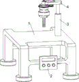
图1为本发明的立体结构示意图。Fig. 1 is a schematic diagram of the three-dimensional structure of the present invention.
图2为本发明固定框和伺服电机等零件的立体结构示意图。Fig. 2 is a three-dimensional structure diagram of parts such as the fixing frame and the servo motor of the present invention.
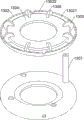
图3为本发明弧形壳和螺纹套等零件的立体结构示意图。Fig. 3 is a three-dimensional structural schematic diagram of parts such as an arc-shaped shell and a threaded sleeve of the present invention.
图4为本发明密封组件的立体结构示意图。Fig. 4 is a three-dimensional schematic diagram of the sealing assembly of the present invention.
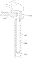
图5为本发明驱动机构的立体结构示意图。Fig. 5 is a schematic perspective view of the drive mechanism of the present invention.
图6为本发明固定塞和转动塞等零件的立体结构示意图。Fig. 6 is a three-dimensional structure diagram of parts such as the fixed plug and the rotating plug of the present invention.
图7为本发明调节部件的立体结构示意图。Fig. 7 is a schematic perspective view of the three-dimensional structure of the adjustment component of the present invention.
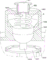
图8为本发明补水组件的立体结构示意图。Fig. 8 is a schematic perspective view of the three-dimensional structure of the water supply assembly of the present invention.
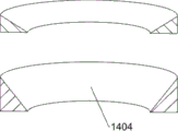
图9本发明分流环的立体结构示意图。Fig. 9 is a schematic diagram of the three-dimensional structure of the diverter ring of the present invention.
附图标记说明:1-车床本体,101-钻头,2-控制终端,3-液压推杆,4-固定框,5-伺服电机,6-第一壳体,601-进水口,602-限位槽,7-转动套,8-齿圈,9-齿轮,10-第二壳体,1001-环形槽,11-弧形壳,1101-弧形板,12-螺纹套,1301-固定板,1302-环形管,13021-第一空腔,13022-第二空腔,1303-连接板,1304-圆环,1305-固定塞,1306-转动塞,1307-直管,1308-滑杆,1309-活塞盘,1310-连接盘,1311-转盘,1312-连接柱,1401-密封塞,1402-弹簧,1403-限位杆,1404-分流环,1501-密封环,1502-支撑板。Explanation of reference signs: 1-lathe body, 101-drill bit, 2-control terminal, 3-hydraulic push rod, 4-fixed frame, 5-servo motor, 6-first housing, 601-water inlet, 602-limit Position slot, 7-rotating sleeve, 8-gear ring, 9-gear, 10-second housing, 1001-annular groove, 11-arc shell, 1101-arc plate, 12-thread sleeve, 1301-fixing plate , 1302-ring pipe, 13021-first cavity, 13022-second cavity, 1303-connecting plate, 1304-ring, 1305-fixed plug, 1306-rotating plug, 1307-straight pipe, 1308-sliding rod, 1309-piston disc, 1310-connecting disc, 1311-rotary disc, 1312-connecting column, 1401-sealing plug, 1402-spring, 1403-limit rod, 1404-splitter ring, 1501-sealing ring, 1502-support plate.
具体实施方式Detailed ways
下面结合附图和具体实施方式对本发明进一步说明。The present invention will be further described below in conjunction with the accompanying drawings and specific embodiments.
实施例1Example 1
一种基于钻头喷射冷却的机电设备加工用数控车床,如图1-图4所示,包括有车床本体1,车床本体1的前侧设置有控制终端2,车床本体1上表面的右侧固接有与控制终端2电连接的液压推杆3,液压推杆3的伸缩端固接有固定框4,固定框4的中部固接有与控制终端2电连接的伺服电机5,固定框4的左侧固接有第一壳体6,第一壳体6的下侧转动连接有转动套7,转动套7的外侧套设有齿圈8,伺服电机5的输出轴固接有与齿圈8啮合的齿轮9,伺服电机5的输出轴通过齿轮9带动齿圈8逆时针转动,齿圈8带动转动套7逆时针转动,转动套7的下侧转动连接有第二壳体10,第一壳体6、转动套7和第二壳体10配合形成储水空腔,第二壳体10设置有花键,第二壳体10滑动连接有钻头101,钻头101设置有与第二壳体10的花键滑动配合的键槽,当钻头101的键槽与第二壳体10的花键1001配合时,钻头定位完成,钻头101受第二壳体10限位无法向上移动,第二壳体10的下侧面固接有周向等间距分布的三个弧形壳11,弧形壳11的材质为弹性材料,弧形壳11将钻头101卡紧,钻头101设置有通水孔,储水空腔内的水穿过钻头101的通水孔,对钻头101冷却,转动套7设置有带动第二壳体10转动的驱动机构。A CNC lathe for electromechanical equipment processing based on drill bit spray cooling, as shown in Figures 1-4, includes a lathe body 1, a
如图3和图4所示,弧形壳11的外侧面设置有螺纹,弧形壳11的外侧套设有螺纹套12,螺纹套12与弧形壳11螺纹配合,螺纹套12转动,三个弧形壳11的下侧相互靠近。As shown in Figures 3 and 4, the outer surface of the arc-
如图4所示,弧形壳11靠近钻头101的一侧固接有弧形板1101,三个弧形板1101的角度之和为360°,三个弧形板1101将钻头101上部的外侧面全部包裹,增加了弧形板1101与钻头101的接触面积,弧形板1101的材质设置为弹性材料,当弧形板1101与钻头101接触时,弧形板1101发生形变,增加弧形板1101内侧面与钻头101的贴合面积,进一步增加了弧形板1101与钻头101的摩擦力,防止钻头101运作时向下移动。As shown in Figure 4, the arc-
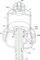
如图5和图6所示,驱动机构包括有固定板1301,固定板1301固接于转动套7内,固定板1301固接有环形管1302,环形管1302位于转动套7内的中部,第二壳体10内固接有连接板1303,环形管1302的内侧面设置有环形卡槽,环形管1302的环形卡槽内转动连接有与连接板1303上侧固接的圆环1304,环形管1302内固接有周向等间距分布的四个固定塞1305,固定塞1305与圆环1304滑动连接,圆环1304固接有周向等间距且位于环形管1302内的四个转动塞1306,转动塞1306与环形管1302滑动连接,固定塞1305和转动塞1306均为缺口圆盘,固定塞1305和转动塞1306将环形管1302内的空腔分隔为等间距分布的四个第一空腔13021和四个第二空腔13022,第一空腔13021内填充有液压油,环形管1302设置有与第二空腔13022连通的通孔,环形管1302设置有用于调节钻头101出水量的调节部件。As shown in Figure 5 and Figure 6, the driving mechanism includes a fixed
如图5-图8所示,调节部件包括有周向等间距分布的四个直管1307,四个直管1307均固接于环形管1302的上侧面,直管1307与相邻的第一空腔13021连通,直管1307滑动连接有滑杆1308,直管1307内的下部滑动连接有与滑杆1308固接的活塞盘1309,第一空腔13021内的液压油进入相邻的直管1307内,并推动活塞盘1309向上移动,直管1307的上侧设置有通孔,用于平衡气压,四个滑杆1308的上部固接有连接盘1310,连接盘1310的中部转动连接有转盘1311,连接盘1310设置有周向等间距分布的散热孔,减少连接盘1310与转盘1311之间产生的热量,转盘1311的上侧面固接有连接柱1312,第一壳体6设置有用于向转动套7内注水的补水组件。As shown in Figures 5-8, the adjustment component includes four
如图8和图9所示,补水组件包括有密封塞1401,密封塞1401滑动连接于第一壳体6内,第一壳体6内存有水,密封塞1401的上部设置为圆柱、下部设置为球形,第一壳体6与密封塞1401密封配合,增加了密封塞1401与第一壳体6之间的接触面积,增加两者之间的密封性,避免第一壳体6内的水泄露,第一壳体6的上侧设置有进水口601,进水口601通过水管与水箱连通,水箱通过水管和进水口601向第一壳体6内补水,密封塞1401与第一壳体6之间固接有弹簧1402,弹簧1402位于第一壳体6内,第一壳体6的上部设置有限位槽602,密封塞1401固接有与限位槽602滑动连接的限位杆1403,限位杆1403的下部为圆柱、上部为矩形板,第一壳体6内固接有分流环1404,分流环1404的内径由上至下逐渐变小。As shown in Fig. 8 and Fig. 9, the water supplement assembly includes a sealing
在本车床对机电设备进行打孔操作之前,操作人员首先将对应的钻头101安装,具体操作如下:操作人员按图1所示的安装方式将钻头101插入三个弧形板1101之间,当钻头101的键槽被第二壳体10的花键限位时,钻头101无法再向上移动,随后操作人员转动螺纹套12,螺纹套12向下移动,螺纹套12的内壁挤压三个弧形壳11的外侧面,弧形壳11受挤压其下侧逐渐靠近钻头101,弧形壳11的下侧带动弧形板1101靠近钻头101并将其卡紧,由于三个弧形板1101的角度之和为360°,三个弧形板1101将钻头101上部的外侧面全部包裹,增加了弧形板1101与钻头101的接触面积,且弧形板1101的材质为弹性材料,当弧形板1101与钻头101接触时,弧形板1101发生形变,增加弧形板1101内侧面与钻头101的贴合面积,进一步增加了弧形板1101与钻头101的摩擦力,防止钻头101运作时向下移动。Before the lathe performs the drilling operation on the electromechanical equipment, the operator first installs the
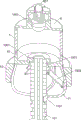
在钻头101安装完成后,操作人员将需要打孔的机电设备放入车床本体1的上侧,并将机电设备所需打孔处与钻头101对齐,随后进行打孔操作,具体操作如下:操作人员通过控制终端2启动伺服电机5,伺服电机5的输出轴通过齿轮9带动齿圈8逆时针转动,齿圈8带动转动套7逆时针转动,转动套7通过固定板1301带动环形管1302逆时针转动,环形管1302带动其内的四个固定塞1305逆时针转动,固定塞1305通过与其相邻第一空腔13021内的液压油带动转动塞1306转动,转动塞1306带动圆环1304逆时针转动,圆环1304通过连接板1303带动第二壳体10逆时针转动,第二壳体10带动弧形壳11和弧形板1101逆时针转动,第二壳体10通过其上的花键带动钻头101逆时针转动,在环形管1302转动的过程中,环形管1302通过直管1307带动滑杆1308逆时针转动,滑杆1308带动连接盘1310转动,而转盘1311不会发生转动,连接盘1310与转盘1311发生摩擦产生热量,由于连接盘1310设置有周向等间距分布的散热孔,降低了连接盘1310与转盘1311的接触面积,减小了产生的热量。After the
在固定塞1305挤压相邻第一空腔13021内液压油的过程中,第一空腔13021内的液压油进入相邻的直管1307内,固定塞1305与相邻转动塞1306之间的距离变小,外界空气通过环形管1302的通孔进入相邻的第二空腔13022内,液压油通过活塞盘1309带动滑杆1308向上移动,直管1307内活塞盘1309上侧的气体通过直管1307上侧的通孔排出,滑杆1308通过连接盘1310带动转盘1311向上移动,转盘1311通过连接柱1312带动密封塞1401向上移动,弹簧1402被压缩,密封塞1401向上移动带动限位杆1403沿限位槽602向上滑动,由于钻头101空转时所受阻力较小,因此第一空腔13021内仅有少量液压油进入相邻的直管1307内,而密封塞1401会向上移动较短距离,密封塞1401的圆柱部分与第一壳体6接触保持密封状态,第一壳体6内的水不会喷出,避免钻头101空转时,水从钻头101的通水孔喷出造成资源浪费。When the fixed
在钻头101转动的过程中,操作人员通过控制终端2启动液压推杆3,液压推杆3带动固定框4向下移动,固定框4带动其上的零件和钻头101向下移动,当钻头101与机电设备接触时,钻头101下端所受的扭力增大,即钻头101转动时的阻力增大,此时,第一空腔13021内的液压油被压入相邻的直管1307内,密封塞1401向上移动解除其与第一壳体6之间的密封,密封塞1401与分流环1404之间形成间隙,第一壳体6内的水通过其与密封塞1401与分流环1404之间的缝隙向下流动,水进入储水空腔后进入钻头101的通水孔内,通过钻头101的通水孔从其下端排出,对钻头101进行冷却的同时将钻出的碎屑冲出,随着钻头101向下移动,钻头101所受的扭力会继续增大,而钻头101与机电设备之间的摩擦力也会越大,密封塞1401会向上移动,密封塞1401与分流环1404之间间隙的横截面积逐渐增大,即水的流通面积逐渐增大,此时,钻头101下端喷出的水量增加,加快对钻头101的冷却速度,当钻头101所钻出孔的深度达到一定值时,钻头101所受的扭力达到定值,钻头101下端的喷水量达到定值,此时的喷水量正好满足钻头101冷却时所需的水。During the rotation of the
当钻头101向下移至指定位置时,控制终端2将液压推杆3停止,钻头101不再向下移动,给机电设备打孔完成,钻头101重新处于空转状态,钻头101所受扭力降低,弹簧1402复位带动密封塞1401向下移动,当密封塞1401与第一壳体6形成密封时,第一壳体6内的水不再流出,钻头101的下端不再出水,由于密封塞1401的下部为球形,因此,增加了密封塞1401下部与第一壳体6之间的接触面积,增加了两者之间的密封性,避免第一壳体6内的水泄露,通过在钻孔完成后立刻将水源切断,避免水资源被浪费,密封塞1401通过连接柱1312和连接盘1310带动四个滑杆1308向下移动,滑杆1308带动活塞盘1309将直管1307内的液压油压入相邻的第一空腔13021内。When the
机电设备打孔完成后,控制终端2将伺服电机5停止,钻头101不再转动,控制终端2启动液压推杆3,液压推杆3带动固定框4和其上的零件向上移动并复位,操作人员将机电设备取下,本车床使用完成,当需要更换钻头101时,操作人员转动螺纹套12,螺纹套12向上移动,弧形壳11的下侧逐渐远离钻头101并复位,弧形壳11的下侧带动弧形板1101远离钻头101并解除对其的卡紧,随后操作人员继续重复上述步骤安装钻头101。After the electromechanical equipment is punched, the
在打不同位置的孔或不同直径的孔时,钻头101的转速不同或钻头101的下移速度不同,钻头101产生的热量不同,例如当钻头101的向下移动的速度快时,钻头101与机电设备摩擦速度增加,钻头101旋转时所受的扭力增大,钻头101与机电设备之间产生的热量增多,同时,钻头101下端排出的水越多,综上所述,在钻头101空转时不进行冷却,避免造成水资源的浪费,且钻头101所需冷却水的量与其自身所受的扭力成一定比例,对钻头101的冷却会进行同步调整,保证钻头101平稳运作,增加钻头101的使用寿命。When drilling holes in different positions or different diameters, the rotating speed of the
实施例2Example 2
在实施例1的基础之上,当需要对不同材料的机电设备打孔时,由于材料不同,钻头101打孔时所产生的热量不同,例如当钻头101所产生的热量较多时,操作人员需提前将分流环1404进行更换,使得分流环1404内侧面的倾斜度增大,即更换为如图9所示上侧的分流环1404。On the basis of Embodiment 1, when it is necessary to punch holes in electromechanical equipment of different materials, the heat generated when the
钻头101打孔的过程中,当不同材料的机电设备与钻头101之间的阻力相同时,钻头101与不同材料的机电设备之间产生的热量不同,密封塞1401向上移动相同距离,由于更换后的分流环1404内侧面的倾斜度增大,密封塞1401与分流环1404之间的水流通量的变化量更大,因此有更多的水从钻头101下端排出,对钻头101进行冷却,通过切换分流环1404,对不同材料的机电设备进行打孔,保证了钻头101的平稳运行。During the drilling process of the
实施例3Example 3
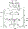
在实施例2的基础之上,还包括有密封组件,密封组件设置于第二壳体10,密封组件用于增加第二壳体10与钻头101之间的密封性,密封组件包括有密封环1501,第二壳体10设置有环形槽1001,环形槽1001位于第二壳体10花键的下侧,密封环1501滑动连接于环形槽1001,密封环1501的材质为弹性材料,密封环1501的下部设置为圆台形,密封环1501的外径下部由上至下逐渐变大,弧形壳11内铰接有周向等间距分布的三个支撑板1502,支撑板1502与密封环1501铰接,弧形壳11通过支撑板1502带动密封环1501向上移动,密封环1501外侧面的下部受第二壳体10的挤压发生形变,紧贴钻头101。On the basis of
在三个弧形板1101将钻头101卡紧的过程中,弧形壳11的下侧逐渐靠近钻头101,以右侧的弧形壳11为例,弧形壳11带动支撑板1502的下侧向左移动,支撑板1502挤压密封环1501的下侧面,由于密封环1501为弹性材料,且密封环1501为圆台形,密封环1501受挤压后沿环形槽1001向上移动,密封环1501外侧面的下部受第二壳体10的挤压发生形变,增加了密封环1501外侧面的下部与第二壳体10之间的密封性,避免钻头101转动的过程中,储水空腔内的水从环形槽1001内泄露,当钻头101使用完成后,操作人员转动螺纹套12,螺纹套12向上移动,螺纹套12带动弧形壳11的下侧远离钻头101,弧形壳11通过支撑板1502带动密封环1501向下移动,解除对钻头101的密封。In the process of clamping the
以上所述仅是本发明的优选实施方式,应当指出,对于本技术领域的普通技术人员来说,在不脱离本发明原理的前提下,还可以做出若干改进和润饰,这些改进和润饰也应视为本发明的保护范围。The above is only a preferred embodiment of the present invention, it should be pointed out that, for those of ordinary skill in the art, without departing from the principle of the present invention, some improvements and modifications can also be made, and these improvements and modifications can also be made. It should be regarded as the protection scope of the present invention.
Claims (7)
Priority Applications (1)
| Application Number | Priority Date | Filing Date | Title |
|---|---|---|---|
| CN202310322552.3A CN116079110B (en) | 2023-03-30 | 2023-03-30 | A CNC lathe for electromechanical equipment processing based on drill bit jet cooling |
Applications Claiming Priority (1)
| Application Number | Priority Date | Filing Date | Title |
|---|---|---|---|
| CN202310322552.3A CN116079110B (en) | 2023-03-30 | 2023-03-30 | A CNC lathe for electromechanical equipment processing based on drill bit jet cooling |
Publications (2)
| Publication Number | Publication Date |
|---|---|
| CN116079110A CN116079110A (en) | 2023-05-09 |
| CN116079110B true CN116079110B (en) | 2023-06-20 |
Family
ID=86210435
Family Applications (1)
| Application Number | Title | Priority Date | Filing Date |
|---|---|---|---|
| CN202310322552.3A Active CN116079110B (en) | 2023-03-30 | 2023-03-30 | A CNC lathe for electromechanical equipment processing based on drill bit jet cooling |
Country Status (1)
| Country | Link |
|---|---|
| CN (1) | CN116079110B (en) |
Families Citing this family (1)
| Publication number | Priority date | Publication date | Assignee | Title |
|---|---|---|---|---|
| CN116890241B (en) * | 2023-09-08 | 2023-11-24 | 江苏泰丰泵业有限公司 | Immersible pump processingequipment with self-locking function |
Family Cites Families (12)
| Publication number | Priority date | Publication date | Assignee | Title |
|---|---|---|---|---|
| JPH10235507A (en) * | 1997-02-24 | 1998-09-08 | Hideaki Otsuka | Drilling method and drilling device |
| AU2012264076B2 (en) * | 2011-05-30 | 2015-06-11 | Kabushiki Kaisha Miyanaga | Coolant supply device and electric drill unit provided with coolant supply device |
| CN103737054A (en) * | 2013-11-26 | 2014-04-23 | 苏州道众机械制造有限公司 | Liquid cooling drill machine |
| CN206009908U (en) * | 2016-08-31 | 2017-03-15 | 王丹丹 | Novel automatic drilling machine |
| CN206153608U (en) * | 2016-08-31 | 2017-05-10 | 浙江汉达机械有限公司 | High -speed drilling machine |
| CN206588358U (en) * | 2017-04-05 | 2017-10-27 | 何嵬 | Bored machine device is used in a kind of high safety performance component of machine processing |
| CN207592824U (en) * | 2017-12-25 | 2018-07-10 | 重庆珑邦机械制造有限公司 | A kind of drilling equipment |
| CN208600783U (en) * | 2018-07-23 | 2019-03-15 | 温岭市太平高级职业中学 | Screw vacuum pump rotor deep hole drilling machine sealing guide device |
| CN112643095A (en) * | 2020-12-09 | 2021-04-13 | 赵可可 | Multi-station hydraulic punching machine |
| CN215698220U (en) * | 2021-08-24 | 2022-02-01 | 河北硕峰农业机械制造有限公司 | A coolant spraying device for multi-station drilling machine |
| CN114643573B (en) * | 2022-04-21 | 2025-02-11 | 上海科莫蜥人工智能科技有限公司 | An industrial intelligent six-axis robot |
| CN218050487U (en) * | 2022-08-17 | 2022-12-16 | 中国民用航空飞行学院 | A kind of titanium alloy cutting drill bit, installation fixture and processing machine tool |
-
2023
- 2023-03-30 CN CN202310322552.3A patent/CN116079110B/en active Active
Also Published As
| Publication number | Publication date |
|---|---|
| CN116079110A (en) | 2023-05-09 |
Similar Documents
| Publication | Publication Date | Title |
|---|---|---|
| CN203542224U (en) | An external cooling to internal cooling tool handle device and cutting device | |
| CN116079110B (en) | A CNC lathe for electromechanical equipment processing based on drill bit jet cooling | |
| CN211448605U (en) | An electronically controlled water plugging and sealing device | |
| CN106670506B (en) | Motor housing Special Purpose Machine for Processing | |
| CN105179388A (en) | Electro-hydraulic actuator of spherical pump for robot | |
| CN111706295B (en) | Radio electromagnetic wave direct-current control pressure-relief sleeve valve | |
| CN104227495B (en) | A kind of heat transferring medium and the cooling device of this heat transferring medium is installed | |
| CN104790884A (en) | Normally-closed strip-shaped slip chuck for small cylinder spring set | |
| CN219641191U (en) | Self-adaptive valve air tightness detection device | |
| CN112576212A (en) | Linkage bypass valve and continuous circulating drilling equipment | |
| CN106334815B (en) | Drilling template with handle bar | |
| CN118328741A (en) | Multi-channel heat exchanger | |
| CN213574003U (en) | Plugging device for coal seam deep hole double-pipe directional drilling machine | |
| CN222798157U (en) | A kind of anti-leakage drip water separator | |
| CN204961463U (en) | Ball pump electricity liquid actuator for robot | |
| CN203334949U (en) | Downhole tool power machine | |
| CN114151411A (en) | Square mode locking oil cylinder device with cooling function | |
| CN210848510U (en) | Long pipe inner ring groove milling equipment | |
| CN220956733U (en) | Cooling structure of transmission screw rod | |
| CN201552468U (en) | Machine tool main spindle heat dissipation structure | |
| CN112343875B (en) | Hydraulic driving device and driving method for slewing equipment | |
| CN207796248U (en) | A grease injection device | |
| CN220956944U (en) | Three-way shunt regulating valve | |
| CN101839353A (en) | Ball valve | |
| CN105127485A (en) | Drilling mold plate |
Legal Events
| Date | Code | Title | Description |
|---|---|---|---|
| PB01 | Publication | ||
| PB01 | Publication | ||
| SE01 | Entry into force of request for substantive examination | ||
| SE01 | Entry into force of request for substantive examination | ||
| GR01 | Patent grant | ||
| GR01 | Patent grant | ||
| PE01 | Entry into force of the registration of the contract for pledge of patent right |
Denomination of invention: A CNC lathe for machining electromechanical equipment based on drill jet cooling Granted publication date: 20230620 Pledgee: Zhejiang Tonglu rural commercial bank Limited by Share Ltd. Feng Chuan branch Pledgor: HANGZHOU FINE METAL MACHINING CO.,LTD. Registration number: Y2025330000651 |
|
| PE01 | Entry into force of the registration of the contract for pledge of patent right |