CN116059712A - Processing apparatus is used in chemical plant sewage discharge detection - Google Patents
Processing apparatus is used in chemical plant sewage discharge detection Download PDFInfo
- Publication number
- CN116059712A CN116059712A CN202310139358.1A CN202310139358A CN116059712A CN 116059712 A CN116059712 A CN 116059712A CN 202310139358 A CN202310139358 A CN 202310139358A CN 116059712 A CN116059712 A CN 116059712A
- Authority
- CN
- China
- Prior art keywords
- box
- fixed
- horizontal
- main shaft
- plate
- Prior art date
- Legal status (The legal status is an assumption and is not a legal conclusion. Google has not performed a legal analysis and makes no representation as to the accuracy of the status listed.)
- Withdrawn
Links
- 239000010865 sewage Substances 0.000 title claims abstract description 49
- 238000001514 detection method Methods 0.000 title claims abstract description 17
- 239000000126 substance Substances 0.000 title claims abstract description 16
- 238000001125 extrusion Methods 0.000 claims abstract description 22
- XLYOFNOQVPJJNP-UHFFFAOYSA-N water Substances O XLYOFNOQVPJJNP-UHFFFAOYSA-N 0.000 claims abstract description 18
- 238000009434 installation Methods 0.000 claims abstract description 15
- 238000004140 cleaning Methods 0.000 claims description 24
- 238000007790 scraping Methods 0.000 claims description 20
- 241000196324 Embryophyta Species 0.000 claims description 15
- 241000220317 Rosa Species 0.000 claims description 12
- 230000000694 effects Effects 0.000 claims description 5
- 239000012535 impurity Substances 0.000 abstract description 29
- 238000001914 filtration Methods 0.000 abstract description 10
- 238000002955 isolation Methods 0.000 abstract description 2
- 230000005540 biological transmission Effects 0.000 description 5
- 238000000034 method Methods 0.000 description 5
- 239000003344 environmental pollutant Substances 0.000 description 3
- 231100000719 pollutant Toxicity 0.000 description 3
- 230000007547 defect Effects 0.000 description 2
- 238000010586 diagram Methods 0.000 description 2
- 238000001179 sorption measurement Methods 0.000 description 2
- 230000009286 beneficial effect Effects 0.000 description 1
- 230000006835 compression Effects 0.000 description 1
- 238000007906 compression Methods 0.000 description 1
- 230000008878 coupling Effects 0.000 description 1
- 238000010168 coupling process Methods 0.000 description 1
- 238000005859 coupling reaction Methods 0.000 description 1
- 238000007599 discharging Methods 0.000 description 1
- 239000010842 industrial wastewater Substances 0.000 description 1
- 238000004519 manufacturing process Methods 0.000 description 1
- 239000000463 material Substances 0.000 description 1
- 235000015097 nutrients Nutrition 0.000 description 1
- 230000036284 oxygen consumption Effects 0.000 description 1
- 244000052769 pathogen Species 0.000 description 1
- 230000001717 pathogenic effect Effects 0.000 description 1
- 239000011148 porous material Substances 0.000 description 1
- 238000004062 sedimentation Methods 0.000 description 1
- 239000007787 solid Substances 0.000 description 1
- 231100001234 toxic pollutant Toxicity 0.000 description 1
Images


Classifications
-
- G—PHYSICS
- G01—MEASURING; TESTING
- G01N—INVESTIGATING OR ANALYSING MATERIALS BY DETERMINING THEIR CHEMICAL OR PHYSICAL PROPERTIES
- G01N33/00—Investigating or analysing materials by specific methods not covered by groups G01N1/00 - G01N31/00
- G01N33/18—Water
-
- B—PERFORMING OPERATIONS; TRANSPORTING
- B01—PHYSICAL OR CHEMICAL PROCESSES OR APPARATUS IN GENERAL
- B01D—SEPARATION
- B01D29/00—Filters with filtering elements stationary during filtration, e.g. pressure or suction filters, not covered by groups B01D24/00 - B01D27/00; Filtering elements therefor
- B01D29/11—Filters with filtering elements stationary during filtration, e.g. pressure or suction filters, not covered by groups B01D24/00 - B01D27/00; Filtering elements therefor with bag, cage, hose, tube, sleeve or like filtering elements
- B01D29/31—Self-supporting filtering elements
- B01D29/35—Self-supporting filtering elements arranged for outward flow filtration
-
- B—PERFORMING OPERATIONS; TRANSPORTING
- B01—PHYSICAL OR CHEMICAL PROCESSES OR APPARATUS IN GENERAL
- B01D—SEPARATION
- B01D29/00—Filters with filtering elements stationary during filtration, e.g. pressure or suction filters, not covered by groups B01D24/00 - B01D27/00; Filtering elements therefor
- B01D29/62—Regenerating the filter material in the filter
- B01D29/64—Regenerating the filter material in the filter by scrapers, brushes, nozzles, or the like, acting on the cake side of the filtering element
-
- B—PERFORMING OPERATIONS; TRANSPORTING
- B01—PHYSICAL OR CHEMICAL PROCESSES OR APPARATUS IN GENERAL
- B01D—SEPARATION
- B01D29/00—Filters with filtering elements stationary during filtration, e.g. pressure or suction filters, not covered by groups B01D24/00 - B01D27/00; Filtering elements therefor
- B01D29/76—Handling the filter cake in the filter for purposes other than for regenerating
- B01D29/86—Retarding cake deposition on the filter during the filtration period, e.g. using stirrers
Landscapes
- Chemical & Material Sciences (AREA)
- Chemical Kinetics & Catalysis (AREA)
- Health & Medical Sciences (AREA)
- Life Sciences & Earth Sciences (AREA)
- Physics & Mathematics (AREA)
- Medicinal Chemistry (AREA)
- Food Science & Technology (AREA)
- Analytical Chemistry (AREA)
- Biochemistry (AREA)
- General Health & Medical Sciences (AREA)
- General Physics & Mathematics (AREA)
- Immunology (AREA)
- Pathology (AREA)
- Engineering & Computer Science (AREA)
- Filtration Of Liquid (AREA)
Abstract
The invention discloses a treatment device for detecting sewage discharge in a chemical plant, which relates to the technical field of sewage treatment and comprises a horizontal pipe box, wherein a vertical pipe opening is fixed on the upper side of the horizontal pipe box, a portal frame is fixed on the upper side of the vertical pipe opening, a water inlet pipe and an electric push rod are arranged on the portal frame, the lower end of the water inlet pipe extends into the vertical pipe opening, a sleeve is sleeved at the lower end of the water inlet pipe in a sliding manner, the lower end of the sleeve penetrates through and is fixedly provided with an extrusion plate, and the telescopic end of the electric push rod is fixedly arranged on the upper surface of the extrusion plate; the inside of horizontal tub of case transversely rotates and installs the main shaft, and steering assembly is connected to the one end of main shaft, realizes rotating through steering assembly, and the middle part of main shaft is fixed with the installation tube, and the swing arm is installed to the other end of main shaft, and the lower extreme of swing arm is fixed with the arc rack. The invention can realize the efficient filtration and isolation of impurities in the sewage, so that the discharged sewage is more convenient for subsequent detection, and the impurities isolated by filtration can be conveniently cleaned and discharged, so that the device can be rapidly put into use again.
Description
Technical Field
The invention relates to the technical field of sewage treatment, in particular to a treatment device for detecting sewage discharge of a chemical plant.
Background
Sewage generally refers to effluent from life and production that is contaminated to some extent. The sewage mainly comprises domestic sewage, industrial wastewater and initial rainwater. The main pollutants of the sewage include pathogen pollutants, oxygen consumption pollutants, plant nutrients, toxic pollutants and the like; moreover, industrial sewage contains a large amount of impurities, and also contains a large amount of insoluble granular impurities, and detection of the granular impurities is very inconvenient.
Through retrieving, chinese patent number CN 107884536A discloses a sewage detection device for mill, which comprises a frame, the frame bottom is provided with the backup pad, backup pad top surface one side is provided with places the case, place case inside bottom surface and be provided with the power, power one side and be located and place case inside bottom surface and be provided with the controller, place case one side and be located backup pad top surface opposite side and be provided with the pivot, pivot one side and be located the backup pad top surface and be provided with first motor, be provided with first gear on the first motor output shaft, the meshing has the second gear on the first gear, the second gear sets up on the pivot output shaft, the frame top surface is provided with the check out test set body, check out test set body one side and be located the frame top surface and be provided with the support frame, support frame one side and be located the frame top surface and be provided with the second motor.
The prior art has the following defects: the prior art cannot realize efficient filtration and cleaning of impurities in the sewage before sewage detection, and brings inconvenience to subsequent detection operation, so the invention provides a treatment device for sewage discharge detection in a chemical plant.
Disclosure of Invention
The invention aims to solve the defects in the prior art and provides a treatment device for detecting sewage discharge of a chemical plant.
In order to achieve the above purpose, the present invention adopts the following technical scheme:
the utility model provides a chemical plant sewage discharges and detects usefulness processing apparatus, includes horizontal tub of case, the upside of horizontal tub of case is fixed with the standpipe mouth, and the upside of perpendicular tub mouth is fixed with the portal frame, installs inlet tube and electric putter on the portal frame, and the lower extreme of inlet tube extends to the standpipe mouth, and the slip cap of inlet tube lower extreme is equipped with the sleeve pipe, and the sheathed tube lower extreme runs through and is fixed with the stripper plate, the flexible end of electric putter is fixed with the upper surface mounting of stripper plate;
the main shaft is transversely rotatably arranged in the transverse pipe box, one end of the main shaft is connected with the steering assembly, the steering assembly is used for realizing rotation, the installation pipe is fixed in the middle of the main shaft, the swing arm is arranged at the other end of the main shaft, the arc-shaped rack is fixed at the lower end of the swing arm, the sub-shaft is transversely rotatably arranged at the lower side position in the transverse pipe box, a plurality of discharge plates are arranged on the sub-shaft, the sewage drain pipe is arranged at the bottom of the transverse pipe box, and the water outlet pipe is arranged on the side surface of the transverse pipe box;
the filter box is fixed on the upper side of the installation pipe, the cleaning assembly is movably arranged on the surface of the filter box, the transverse rotating rail is movably arranged on the outer side of the cleaning assembly and close to the position of the upper end, the inner wall of the transverse pipe box of the transverse rotating rail is in sliding connection, the filter box follows the main shaft to vertically rotate in the transverse pipe box for reversing, and meanwhile, the filter box transversely rotates relative to the installation pipe.
Further, the steering assembly comprises a first motor which is arranged on the inner wall of the horizontal pipe box, a worm is arranged on a driving shaft of the first motor, a worm wheel is arranged at one end of the main shaft, and the worm is meshed with the worm wheel for transmission.
Further, the cleaning assembly comprises a second motor arranged in the installation tube, a driving shaft of the second motor penetrates into the filter box and is provided with an upper scraping plate, two ends of the upper scraping plate are respectively and vertically provided with an inner scraping plate, the upper end of the inner scraping plate is respectively provided with an outer scraping plate through a transverse plate, and the lower end of the outer scraping plate is respectively provided with a lower scraping plate; the bottom surface of the upper scraping plate is in friction contact with the inner bottom wall of the filter box, the inner scraping plate is in friction contact with the inner side wall of the filter box, the outer scraping plate is in friction contact with the outer side wall of the filter box, and the lower scraping plate is in friction contact with the outer bottom wall of the filter box; the outer side of the outer scraping plate is fixedly provided with a transverse sliding shaft which is in sliding connection with the transverse rotating rail.
Further, the outside of horizontal rotation rail is installed vertical slide shaft, and vertical spout has been seted up to the inner wall of horizontal tub of case, and vertical slide shaft and vertical spout slip match.
Further, the downside activity of stripper plate is equipped with disturbance mechanism, and disturbance mechanism is rotatory for stripper plate and rose box transversely for disturb sewage in the rose box, still be used for the inner wall of rose box and the bottom surface of stripper plate to clean simultaneously.
Further, the disturbance subassembly includes the ring gear of transversely rotating the installation with the portal frame, the outside of ring gear is equipped with rather than the second gear of meshing, the drive shaft coupling of second gear and third motor, third motor and portal frame fixed mounting, the inboard of ring gear is equipped with a plurality of long tooth poles rather than the meshing, and long tooth pole is vertical slip for the ring gear, the lower extreme of long tooth pole and the outside sliding connection of stripper plate, and the disturbance board is installed to the lower extreme of long tooth pole, the top surface of disturbance board and the bottom surface friction contact of stripper plate.
Further, a sliding block is fixed on the side face of the bottom of the long tooth bar, an annular groove is formed in the side face of the extrusion plate, the sliding block and the annular groove are slidably mounted, and the long tooth bar transversely slides relative to the extrusion plate.
Further, the disturbance plate is a plurality of thin plates made of rubber materials.
Compared with the prior art, the invention has the beneficial effects that:
1. according to the invention, impurities can be filtered before sewage detection, the impurities are filtered by the arranged filter boxes, and the filter boxes are matched with the extrusion effect of the extrusion plate, so that the filtering speed is higher, the filtering efficiency is improved, and the sewage can be discharged after various solid impurities and sewage are separated by filtering, so that the subsequent detection operation is performed; the detection operation can be more convenient.
2. The invention can conveniently clean and discharge the filtered impurities, and can realize the rotation reversing of the filter box by simultaneously cleaning the inner surface and the outer surface of the filter box during cleaning, thereby discharging the impurities at the filter box to the inner bottom of the transverse pipe box, and then being matched with the driving of the discharge plate, so that the impurities can be rapidly discharged from the transverse pipe box by utilizing the blow-off pipe, the high-efficiency cleaning and discharge of the impurities can be realized, and the device can be rapidly put into use again.
In conclusion, the invention can realize high-efficiency filtration and isolation of impurities in sewage, so that the discharged sewage is more convenient for subsequent detection, the impurities isolated by filtration can be conveniently cleaned and discharged, and the device can be rapidly put into use again.
Drawings
The accompanying drawings are included to provide a further understanding of the invention and are incorporated in and constitute a part of this specification, illustrate the invention and together with the embodiments of the invention, serve to explain the invention.
FIG. 1 is a schematic diagram of the overall structure of the present invention;
FIG. 2 is an internal cross-sectional view of the present invention;
FIG. 3 is a schematic view of the compression plate of FIG. 2 being compressed into a filter box;
FIG. 4 is a schematic view of the filter housing of FIG. 2 after rotation;
FIG. 5 is an internal cross-sectional view of the mounting tube, the lateral rotation rail, and the filter box;
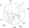
FIG. 6 is an enlarged view of the portion a of FIG. 5;
FIG. 7 is a schematic diagram of the transmission of the main shaft and the sub-shaft through the swing arm, the arc-shaped rack and the first rack;
FIG. 8 is a schematic structural view of a cleaning assembly;
FIG. 9 is a schematic view of the installation of the disturbance assembly relative to the gantry and the stripper plate;
FIG. 10 is an enlarged view of the portion b of FIG. 9;
fig. 11 is a schematic view of the engagement of the toothed ring with the long toothed bar.
In the figure: a horizontal tube box 1, a vertical tube opening 2, a portal frame 3, a water inlet tube 4, a sleeve 5, an electric push rod 6, a squeeze plate 7, a main shaft 8, a mounting tube 9, a steering component 10, a first motor 101, a worm 102, a worm gear 103, a filter box 11, a cleaning component 12, a second motor 121, an upper scraping plate 122, an inner scraping plate 123, an outer scraping plate 124, a lower scraping plate 125, a horizontal sliding shaft 126, a horizontal rotating rail 13, a sub-shaft 14, a discharge plate 15, a blow-down tube 16, a first gear 17, an arc-shaped rack 18, a swing arm 19, a water outlet tube 20, a vertical sliding shaft 21, a vertical sliding groove 22, a turbulence component 23, a third motor 231, a second gear 232, a toothed ring 233, a limiting guide rail 234, a long toothed bar 235, a turbulence plate 236, a sliding block 237 and an annular groove 238.
Detailed Description
The technical solutions in the embodiments of the present invention will be clearly and completely described below with reference to the accompanying drawings in the embodiments of the present invention;
referring to fig. 1-11, a treatment device for detecting sewage discharge in a chemical plant comprises a horizontal pipe box 1, wherein a vertical pipe opening 2 is fixed on the upper side of the horizontal pipe box 1, a portal frame 3 is fixed on the upper side of the vertical pipe opening 2, a water inlet pipe 4 and an electric push rod 6 are installed on the portal frame 3, the lower end of the water inlet pipe 4 extends into the vertical pipe opening 2, a sleeve 5 is sleeved at the lower end of the water inlet pipe 4 in a sliding manner, a squeezing plate 7 is penetrated and fixed at the lower end of the sleeve 5, and the telescopic end of the electric push rod 6 is fixedly installed on the upper surface of the squeezing plate 7;
the inside of the horizontal tube box 1 is transversely rotatably provided with a main shaft 8, one end of the main shaft 8 is connected with a steering assembly 10, the steering assembly 10 rotates through the steering assembly 10, the steering assembly 10 comprises a first motor 101 which is arranged on the inner wall of the horizontal tube box 1, a driving shaft of the first motor 101 is provided with a worm 102, one end of the main shaft is provided with a worm wheel 103, and the worm 102 is meshed with the worm wheel 103 for transmission.
The middle part of the main shaft 8 is fixedly provided with a mounting pipe 9, the other end of the main shaft 8 is provided with a swing arm 19, the lower end of the swing arm 19 is fixedly provided with an arc-shaped rack 18, a sub-shaft 14 is transversely and rotatably arranged at the lower side position inside the transverse pipe box 1, a plurality of discharge plates 15 are arranged on the sub-shaft 14, the bottom of the transverse pipe box 1 is provided with a drain pipe 16, and the side surface of the transverse pipe box 1 is provided with a water outlet pipe 20;
the filter tank 11 is fixed on the upper side of the installation tube 9, the cleaning component 12 is movably arranged on the surface of the filter tank 11, the transverse rotating rail 13 is movably arranged on the outer side of the cleaning component 12 and close to the upper end, the transverse rotating rail 13 is in sliding connection with the inner wall of the transverse tube tank 1, the filter tank 11 follows the main shaft 8 to vertically rotate in the transverse tube tank 1 for reversing, and meanwhile, the filter tank 11 transversely rotates relative to the installation tube 9.
Sewage is discharged into the filter tank 11 through the water inlet pipe 4 and the sleeve pipe 5, impurities in the sewage are filtered and isolated through the filter tank 11, the impurities can be isolated in the filter tank 11, the sewage can pass through the filter holes of the filter tank 11 and is collected to the bottom of the filter tank 11, and the sewage is discharged through the water outlet pipe 20 after one end of sedimentation time, and the water outlet pipe 20 is connected with a sewage detection instrument for detecting sewage. Because the impurity in the water is isolated and filtered, the water can be more quickly and conveniently detected in the follow-up detection process, and the detection efficiency is improved.
When sewage is injected into the filter tank 11 and filtered by the filter tank 11, the electric push rod 6 controls the squeeze plate 7 to move into the filter tank 11, and at the moment, the water pressure in the filter tank 11 is increased, so that the filtering speed and efficiency of impurities are improved. Wherein, when the extrusion plate 7 moves downwards or upwards, the water inlet pipe 4 and the sleeve 5 are in sliding connection in time, and the normal conveying of sewage is maintained.
After the impurities in the sewage are filtered, the impurities in the filter tank 11 need to be cleaned and discharged, wherein the cleaning assembly 12 is utilized to simultaneously clean the inner bottom wall, the inner side wall, the outer side wall and the outer bottom wall of the filter tank 11 during cleaning, so that the smoothness of the filter holes of the filter tank 11 is maintained. After cleaning, the filter tank 11 is vertically rotated and reversed, so that the state that the opening is upward in fig. 2 is converted into a turntable with the downward opening in fig. 4, and impurities can be thoroughly transferred to the bottom of the horizontal pipe tank 1, thereby facilitating the subsequent realization of the discharge of the impurities.
The cleaning assembly 12 comprises a second motor 121 installed in the installation pipe, a driving shaft of the second motor 121 penetrates into the filter box and is provided with an upper scraper 122, two ends of the upper scraper 122 are respectively vertically provided with an inner scraper 123, the upper ends of the inner scrapers 123 are respectively provided with an outer scraper 124 through a transverse plate, and the lower ends of the outer scrapers 124 are respectively provided with a lower scraper 125; the bottom surface of the upper scraper 122 is in friction contact with the inner bottom wall of the filter box 11, the inner scraper 123 is in friction contact with the inner side wall of the filter box 11, the outer scraper 124 is in friction contact with the outer side wall of the filter box 11, and the lower scraper 125 is in friction contact with the outer bottom wall of the filter box 11; a lateral sliding shaft 126 is fixed to the outer side of the outer scraper 124, and the lateral sliding shaft 126 is slidably connected to the lateral rotation rail 13.
The outside of the transverse rotating rail 13 is provided with a vertical sliding shaft 21, the inner wall of the transverse pipe box 1 is provided with a vertical sliding groove 22, and the vertical sliding shaft 21 is matched with the vertical sliding groove 22 in a sliding way. In the vertical rotation reversing process of the filter box 11, the vertical sliding shaft 21 is in sliding connection with the vertical sliding groove 22, so that the filter box 11 and the transverse rotating rail 13 can vertically rotate relative to the transverse pipe box 1, and the process stability is high.
The cleaning process of the filter box 11 by the cleaning assembly 12 is as follows: through the drive of second motor 121 for upper scraper 122 rubs the interior bottom wall of rose box 11, and interior scraper 123 rubs the inside wall of rose box 11, and outer scraper 124 rubs the outside wall of rose box 11, and lower scraper 125 rubs the outer bottom wall of rose box 11, thereby realizes the cleanness with each surface of rose box 11, thoroughly scrapes the impurity of its surface adsorption, and guarantees the smoothness of its filtration pore.
Wherein the cleaning assembly 12 is slidingly engaged with the lateral rotation rail 13 by means of a lateral sliding shaft 126, so that the cleaning assembly 12 as a whole remains laterally slid with the filter box 11.
The rotation reversing operation of the filter tank 11 is as follows: the worm 102 is controlled to be meshed with the worm wheel 103 by the first motor 101 in the rotating assembly 10, so that the mounting box 9, the filter box 11 and the cleaning assembly 12 are controlled to realize vertical rotation reversing relative to the transverse pipe box 1 by taking the main shaft 8 as a center, and impurities in the filter box 11 can be dumped to the bottom of the transverse pipe box 1 to wait for subsequent discharge;
when the main shaft 8 rotates, the arc-shaped rack 18 arranged at the lower end of the swing arm 19 is meshed with the first gear 17 for transmission, so that the control sub-shaft 14 rotates, and impurities at the bottom of the horizontal pipe box 1 are stirred by the discharge plate 15, so that the impurities can be discharged from the blow-off pipe 16 more smoothly, and the blow-off efficiency is higher.
In addition, the invention is movably provided with the disturbance mechanism 23 at the lower side of the extrusion plate 7, the disturbance mechanism 23 transversely rotates relative to the extrusion plate 7 and the filter tank 11 and is used for disturbing sewage in the filter tank 11 and cleaning the inner wall of the filter tank 11 and the bottom surface of the extrusion plate 7.
The disturbance subassembly 23 includes the ring gear 233 with portal frame 3 transverse rotation installation, the outside of ring gear 233 is equipped with the second gear 232 rather than meshing, second gear 232 is connected with the drive shaft of third motor 231, third motor 231 and portal frame 3 fixed mounting, the inboard of ring gear 233 is equipped with a plurality of long tooth poles 235 rather than meshing, and long tooth pole 235 vertically slides for ring gear 233, the lower extreme of long tooth pole 235 and the outside sliding connection of stripper plate 7, and the disturbance board 236 is installed to the lower extreme of long tooth pole 235, the top surface of disturbance board 236 and the bottom surface friction contact of stripper plate 7. In this embodiment, the disturbance plate 236 is a plurality of thin plates made of rubber.
The side of the bottom of the long tooth rod 235 is fixed with a sliding block 237, the side of the extrusion plate 7 is provided with an annular groove 238, the sliding block 237 and the annular groove 238 are slidably installed, and the long tooth rod 235 transversely slides relative to the extrusion plate 7.
When sewage is discharged into the filter tank 11 and pressurized and filtered, the sewage can be disturbed by the disturbance component 23, and the disturbance process of the disturbance component 23 is as follows: the third motor 231 is used for controlling the second gear 232 to be meshed with the toothed ring 234 for transmission, controlling the toothed ring 234 to rotate, enabling the toothed ring 234 to be meshed with the long toothed rod 235 and driving the upper toothed rod 235 and the disturbance plate 236 at the lower end of the upper toothed rod 235 to transversely rotate relative to the extrusion plate 7, and at the moment, the sewage can be disturbed through the rotation of the disturbance plate 236;
in addition, the friction effect with the bottom surface of the extrusion plate 7 can be utilized by the disturbance plate 236, so that the bottom surface of the extrusion plate 7 is prevented from adsorbing impurities, and meanwhile, the disturbance plate 236 is in friction contact with the inner bottom surface of the filter tank 11, so that the adsorption of impurities on the inner bottom surface of the filter tank 11 can be reduced, the auxiliary cleaning effect is realized, and the smoothness of the filter holes of the filter tank 11 can be ensured.
Claims (8)
1. The utility model provides a chemical plant sewage discharges and detects usefulness processing apparatus, includes horizontal tub of case (1), its characterized in that, the upside of horizontal tub of case (1) is fixed with standpipe mouth (2), and the upside of standpipe mouth (2) is fixed with portal frame (3), installs inlet tube (4) and electric push rod (6) on portal frame (3), and the lower extreme of inlet tube (4) is to stretching in standpipe mouth (2), and the slip cap of inlet tube (4) lower extreme is equipped with sleeve pipe (5), and the lower extreme of sleeve pipe (5) runs through and is fixed with stripper plate (7), the flexible end of electric push rod (6) is fixed with the upper surface mounting of stripper plate (7);
the inside of the horizontal pipe box (1) transversely rotates and installs a main shaft (8), one end of the main shaft (8) is connected with a steering assembly (10), the steering assembly (10) is used for realizing rotation, an installation pipe (9) is fixed in the middle of the main shaft (8), the other end of the main shaft (8) is provided with a swinging arm (19), the lower end of the swinging arm (19) is fixed with an arc-shaped rack (18), the lower side position inside the horizontal pipe box (1) transversely rotates and installs a sub-shaft (14), a plurality of discharge plates (15) are installed on the sub-shaft (14), a blow-down pipe (16) is installed at the bottom of the horizontal pipe box (1), and a water outlet pipe (20) is installed on the side surface of the horizontal pipe box (1);
the installation pipe (9) upside is fixed with rose box (11), and the surface activity of rose box (11) is equipped with clean subassembly (12), and the outside of clean subassembly (12) and the position department movable mounting that is close to the upper end have horizontal rotation rail (13), and the inner wall sliding connection of horizontal tub of case (1) of horizontal rotation rail (13), rose box (11) follow main shaft (8) vertical rotation switching-over in horizontal tub of case (1), rose box (11) are horizontal rotation for installation pipe (9) simultaneously.
2. The treatment device for detecting sewage discharge in a chemical plant according to claim 1, wherein the steering assembly (10) comprises a first motor (101) mounted on the inner wall of the horizontal pipe box (1), a worm (102) is mounted on a driving shaft of the first motor (101), a worm wheel (103) is mounted on one end of the main shaft, and the worm (102) is meshed with the worm wheel (103).
3. The treatment device for detecting sewage discharge in a chemical plant according to claim 2, wherein the cleaning assembly (12) comprises a second motor (121) installed in an installation tube, a driving shaft of the second motor (121) penetrates into the filter tank and is provided with an upper scraper (122), two ends of the upper scraper (122) are respectively vertically provided with an inner scraper (123), the upper ends of the inner scrapers (123) are respectively provided with an outer scraper (124) through a transverse plate, and the lower ends of the outer scrapers (124) are respectively provided with a lower scraper (125); the bottom surface of the upper scraping plate (122) is in friction contact with the inner bottom wall of the filter box (11), the inner scraping plate (123) is in friction contact with the inner side wall of the filter box (11), the outer scraping plate (124) is in friction contact with the outer side wall of the filter box (11), and the lower scraping plate (125) is in friction contact with the outer bottom wall of the filter box (11); and a transverse sliding shaft (126) is fixed on the outer side of the outer scraper (124), and the transverse sliding shaft (126) is in sliding connection with the transverse rotating rail (13).
4. A treatment device for sewage discharge detection in a chemical plant according to claim 3, wherein the outer side of the horizontal rotation rail (13) is provided with a vertical sliding shaft (21), the inner wall of the horizontal pipe box (1) is provided with a vertical sliding groove (22), and the vertical sliding shaft (21) is matched with the vertical sliding groove (22) in a sliding manner.
5. The treatment device for detecting sewage discharge in a chemical plant according to any one of claims 1 to 4, wherein a disturbance mechanism (23) is movably arranged at the lower side of the extrusion plate (7), and the disturbance mechanism (23) rotates transversely relative to the extrusion plate (7) and the filter tank (11) and is used for disturbing sewage in the filter tank (11) and cleaning the inner wall of the filter tank (11) and the bottom surface of the extrusion plate (7).
6. The treatment device for sewage discharge detection in a chemical plant according to claim 5, wherein the disturbance component (23) comprises a toothed ring (233) which is transversely rotatably installed on the gantry (3), a second gear (232) meshed with the toothed ring (233) is arranged on the outer side of the toothed ring (233), the second gear (232) is connected with a driving shaft of a third motor (231), the third motor (231) is fixedly installed on the gantry (3), a plurality of long toothed bars (235) meshed with the toothed ring (233) are arranged on the inner side of the toothed ring (233), the long toothed bars (235) vertically slide relative to the toothed ring (233), the lower ends of the long toothed bars (235) are slidably connected with the outer side of the extrusion plate (7), disturbance plates (236) are installed on the lower ends of the long toothed bars (235), and the top surfaces of the disturbance plates (236) are in friction contact with the bottom surfaces of the extrusion plate (7).
7. The treatment device for detecting sewage discharge in a chemical plant according to claim 6, wherein a slide block (237) is fixed on the side surface of the bottom of the long toothed rod (235), an annular groove (238) is formed in the side surface of the extrusion plate (7), the slide block (237) is slidably mounted with the annular groove (238), and the long toothed rod (235) transversely slides relative to the extrusion plate (7).
8. The treatment device for detecting sewage discharge from a chemical plant according to claim 6, wherein said disturbance plate (236) is a plurality of thin plates made of rubber.
Priority Applications (1)
| Application Number | Priority Date | Filing Date | Title |
|---|---|---|---|
| CN202310139358.1A CN116059712A (en) | 2023-02-20 | 2023-02-20 | Processing apparatus is used in chemical plant sewage discharge detection |
Applications Claiming Priority (1)
| Application Number | Priority Date | Filing Date | Title |
|---|---|---|---|
| CN202310139358.1A CN116059712A (en) | 2023-02-20 | 2023-02-20 | Processing apparatus is used in chemical plant sewage discharge detection |
Publications (1)
| Publication Number | Publication Date |
|---|---|
| CN116059712A true CN116059712A (en) | 2023-05-05 |
Family
ID=86176675
Family Applications (1)
| Application Number | Title | Priority Date | Filing Date |
|---|---|---|---|
| CN202310139358.1A Withdrawn CN116059712A (en) | 2023-02-20 | 2023-02-20 | Processing apparatus is used in chemical plant sewage discharge detection |
Country Status (1)
| Country | Link |
|---|---|
| CN (1) | CN116059712A (en) |
-
2023
- 2023-02-20 CN CN202310139358.1A patent/CN116059712A/en not_active Withdrawn
Similar Documents
| Publication | Publication Date | Title |
|---|---|---|
| CN112704945B (en) | Waste water treatment equipment is used in chemical fertilizer processing convenient to filter screen is dismantled | |
| CN112057923A (en) | Primary sewage impurity recovery environmental protection processing apparatus | |
| CN108117112B (en) | Treatment device for sewage | |
| CN108325242A (en) | A kind of Industrial Wastewater Treatment biochemistry settler | |
| CN214680224U (en) | High-efficient stirring mud scraper of adjustable height | |
| CN208840150U (en) | A kind of New test tube rack for cleaning | |
| CN111747509B (en) | Automatic clear up sewage treatment plant of active biological charcoal | |
| CN116854242A (en) | Biological treatment device for chemical wastewater | |
| CN116059712A (en) | Processing apparatus is used in chemical plant sewage discharge detection | |
| CN111252941A (en) | Factory sewage treatment device based on capacitive sensing | |
| CN207950795U (en) | A kind of waste water control exclusion device | |
| CN216259361U (en) | Domestic sewage treatment is with recovery pond | |
| CN114163016B (en) | Sewage discharge front purification treatment equipment | |
| CN207042058U (en) | A kind of environmentally friendly ore cleaning sullage filtration processing equipment | |
| CN115974189A (en) | Garbage incineration leachate treatment device and use method | |
| CN216337197U (en) | Municipal administration sludge treatment device | |
| CN213537684U (en) | Municipal sludge treatment device with solid-liquid separation function | |
| CN114230073A (en) | Water purifier with prevent blockking up function | |
| CN212236250U (en) | Circulating sewage treatment device | |
| CN210278440U (en) | Energy-concerving and environment-protective waste residue filtration equipment | |
| CN111348777A (en) | Automatic sewage treatment device | |
| CN207483598U (en) | A kind of rapidly and efficiently sludge dehydration device | |
| CN108144347B (en) | Method for rapidly treating sewage | |
| CN219595981U (en) | Papermaking wastewater filtering treatment device | |
| CN219596106U (en) | Environment-friendly water treatment filtering device |
Legal Events
| Date | Code | Title | Description |
|---|---|---|---|
| PB01 | Publication | ||
| PB01 | Publication | ||
| WW01 | Invention patent application withdrawn after publication | ||
| WW01 | Invention patent application withdrawn after publication |
Application publication date: 20230505 |