The present application claims the benefit of U.S. non-provisional patent application No. 16/922,289, filed 7 months 7 in 2020. The subject matter of this previously filed application is hereby incorporated by reference in its entirety.
Detailed Description
Some embodiments relate to a UI descriptor, a UI object library, a UI object repository, and/or a UI object browser for RPA. UI elements (e.g., text fields, buttons, tabs, menus, check boxes, etc.) on a screen may be grouped by application, version of application, application screen, and collection of UI elements, and each screen has multiple UI elements. As used herein, a "screen" is an image of an application UI or a portion of an application UI at a point in time. In this context, an "application" or version of a given application may be a union of screens. In some embodiments, each UI element may be described by one or more UI descriptors. UI elements, UI descriptors, applications and application screens are UI objects. In some embodiments, the UI elements and screens may be further differentiated into specific types of UI elements (e.g., buttons, check boxes, text fields, etc.) and screens (e.g., top window, modality window, pop-up window, etc.).
The UI object browser may access a library of UI objects that may be grouped by application, version of application, application screen, collection of UI elements, combinations thereof, and the like. In some embodiments, the UI objectThe library may be stored in a UI object repository. As used herein, a UI object repository is a collection of UI object libraries. In some embodiments, the UI object repository may be NuGet TM Feeds, web services, etc.
The object browser may be used in some embodiments to navigate, manage, and edit UI object libraries in the UI object repository. In some embodiments, the UI object repository of the UI object library may facilitate managing, reusing, and increasing reliability of UI descriptors in the project. In some embodiments, the UI descriptors may be added to the UI library and published or republished for global reuse in the UI object repository. The UI object browser may facilitate reusability of the UI element identification framework and its derivatives by providing access to the UI object repository and its UI object library.
To make the UI object reusable, it can be extracted into a UI object library that can be referenced by the RPA flow. For example, when a selector or other UI descriptor is modified due to a new version of an application, the library may be recreated (or reissued) to include the modified UI descriptor. The RPA flow using the UI object library may then invoke the modified UI descriptor version. In some embodiments, for RPA flows, references to new Application Programming Interfaces (APIs) associated with new libraries may be modified manually by a developer, via a software tool (e.g., a tool that goes through the RPA flow and updates UI descriptor references when a selector or other component thereof changes), or automatically.
In some embodiments, packages of UI objects may be appended as dependencies (e.g., nuGet TM And (5) packaging). However, in some embodiments, the UI objects may be obtained via one or more API calls to the web service. This enables UI objects to be stored remotely and retrieved and used during automation.
Initial construction of UI descriptors previously required the developer to have technical knowledge of what happens behind the UI descriptors. However, many RPA procedures are no longer built by software developers. For example, these people may use UiPath studio TM Creating RPA workflow does not require extensive programming knowledge. Some embodiments allow creation of RPA workflow individualsThe person reuses the descriptors, which provides time savings because if the appropriate UI descriptor is available to the person creating the RPA workflow, then the software developer is not required to build a new UI descriptor from scratch.
The UI elements added to the UI object library may represent selectors for the RPA workflow. To automate specific operations in the UI, the RPA robot may interact with various windows, buttons, drop-down lists, and/or other graphical elements. Conventionally, this is done using the expected screen positions of the UI elements. However, this is unreliable.
Some embodiments use selectors to overcome the problems associated with fixed coordinate identifications by storing the properties of the UI element and its parent element in an XML fragment. Although the selector may be automatically generated in some embodiments where the UI is static, some software programs, such as some web applications, have varying layout and characteristic nodes of variable values. These changes may not be easily predictable, and this previously required some selector generation manually. However, the object browser of some embodiments may overcome this problem.
In some embodiments, the selector is a type of UI descriptor that may be used to detect the UI element. In some embodiments, the selector has the following structure:
<node_1/><node_2/>...<node_N/>
the last node represents the GUI element of interest and all previous nodes represent the parent element of that element. < node_1> is commonly referred to as the root node and represents the top window of the application.
Each node may have one or more characteristics that help to properly identify a particular level of the selected application. In some embodiments, each node has the following format:
<ui_system attr_name_1='attr_value_1'...attr_name_N='attr_value_N'/>
each characteristic may have an assigned value and a characteristic having a constant value may be selected. This is because each time an application is launched, a change to the property value may cause the selector to fail to correctly identify the associated element.
UI object library descriptors can be added directly to RPA workflow activities, saving the time required for a developer to create custom selectors for the activities. The object browser may provide a database storing the created selector in an object library to enable reusability of the UI descriptor. An object library is defined herein as a collection of UI descriptors corresponding to one or more screens from a certain version of an application. The UI descriptor is a set of instructions for finding a UI element. In some embodiments, the UI descriptor is a packaged data/structure format that includes UI element selector(s), anchor selector(s), computer Vision (CV) descriptor(s), unified target descriptor(s), screen image capture (context), element image capture, other metadata (e.g., application and application version), combinations thereof, and the like. The encapsulated data/structure format may be extended with future updates of the platform and is not limited to the above definition. Any suitable UI descriptor for identifying the UI elements on the screen may be used without departing from the scope of the invention. The unified target descriptor links together multiple types of UI descriptors. The unified target descriptor may function like a Finite State Machine (FSM), where in a first context, a first UI descriptor mechanism is applied, in a second context, a second UI descriptor is applied, and so on.
In some embodiments, the RPA designer application may ask the user what type(s) of application the user plans to automate. For example, the user may specify
Etc. Since RPA applications already include screen descriptors in the UI object library for those applications, the applications can be programmed with logic on how to automate those applications. Out-of-box selectors for various versions of these applications may be available, and a user may be able to specify version(s) to be automated.
As used herein, the terms "user" and "developer" are used interchangeably. The user/developer may or may not have programming and/or technical knowledge. For example, in some embodiments, a user/developer may create an RPA workflow by configuring activities in the RPA workflow without requiring manual encoding. In some embodiments, this may be accomplished by, for example, clicking and dragging and dropping various features.
Conventionally, making a selector reliable requires testing, knowledge of the inherent details of the selector, and so forth. This makes it difficult or impossible for a person without technical knowledge to create/refine the selector. By providing a library of normal running selectors for common UI elements and tasks, some embodiments allow non-technicians to develop automation to work in production. The user may indicate a screen of the application version to be automated and the RPA development application may acquire the screen. The user may then interact with the screen to define what he or she wants to do.
In some embodiments, as new UI descriptors are created and/or existing UI descriptors are modified, a global database of UI object libraries may be established, which may be shared, collaborated, and possibly sourced. In some embodiments, taxonomies and ontologies may be used. Applications, versions, screens, UI elements, descriptors, etc. may be defined as a taxonomy, which is a hierarchy of subcategories.
However, many real world concepts are not easily organized into categories. Instead, they may be closer to the concept of a mathematical ontology. In an ontology, the relationships between categories are not necessarily hierarchical. For example, a button on a screen, when clicked, brings the user to another screen, cannot be easily captured by the classification of that screen, because the next screen is not in the hierarchy. When constructing a graph representing this situation, the object browser of an application can be modeled as an ontology that allows interactions to be created between UI elements on the same screen or different screens, and provides more information about how the UI elements relate to each other.
Consider an example of clicking the ok button to enter the employee screen. The architecture of the ontology may enable the designer application to suggest that the user screen employees on the next screen. The ontology information of the relationship between these screens allows the designer application to do so via the determine button. By defining a graph structure that is not necessarily a tree, but rather one that is related to what the application is actually doing, more complex and rich relationships can be captured.
Some embodiments pertain to or include a logger that allows screen and UI elements to be retrieved from an application more quickly. For example, if a given screen has 250 different UI elements, some time may be required to acquire them one by one. The screen pointer may be used to obtain all editable UI elements. This may help create a first version of the tree or ontology.
In some embodiments, the object browser may be exposed as a web service. If the user updates the selector or other UI descriptor at run-time, the RPA bot may invoke the latest version of the service if properly configured. This allows the RPA robot to always use the current version of the UI descriptor.
UI descriptors can be extracted from the activity in the RPA workflow and added to a structured schema that groups UI descriptors by UI application, screen, and UI elements. In some embodiments, the UI descriptor may be part of one item for extensive reuse, part of a global repository for testing purposes, or part of a UI object library for global cross-item sharing. In some embodiments, the object library is an encapsulation of UI descriptors grouped by application, version of application, and screen. UI descriptors may be defined and added to an object library, which in some embodiments may be installed in other items as dependent items after release. This makes the object library of UI descriptors available for reuse. In some embodiments, the UI application is a target application having multiple versions, where each version has multiple screens.
UI object repository and UI descriptor reuse may be beneficial for various reasons. For example, if the location, appearance, and/or functionality of a UI element in an application changes, the UI descriptor may be changed, and the change may then be propagated to the activity using the UI descriptor. Thus, reusability may be provided at the level of identifying graphical elements in the UI.
This may be particularly advantageous for adapting to new versions of an application. For new versions, the software developer may only need to update the UI descriptor and/or develop some new selectors from scratch, thereby greatly reducing development time. For example, for a web page, hypertext markup language (HTML) may be checked to obtain a path for UI elements of the corresponding selector. The selector of the corresponding UI element may be different in different web browsers and/or different versions of the same web browser. This concept may also be applicable to visual desktop, server, smart phone and tablet computer applications. The UI object library may include the actual selector of the application, which is only one type of UI descriptor according to the description above. For one or more applications, the UI object library may have a plurality of different types of UI descriptors. UI descriptors can also refer to different techniques of building an application. For example, different UI descriptors can be created and used for independent desktop, web, and mobile applications. For one technique you may want to use the selector, and for another technique you may want to use the CV descriptor, etc.
In some embodiments, the UI descriptor may work with a unified target by performing image detection and definition in the unified target that encompasses all UI detection mechanisms. The unified goal may incorporate multiple techniques of identifying and automating UI elements into a single cohesive approach. The unified goal may prioritize selector-based and driver-based UI detection mechanisms and back to the CV to find the image if the first two mechanisms are unsuccessful. In some embodiments, the selector editor and the UI browser may be configured to support unified goals.
In some embodiments, the designer application includes a portion or panel that is an "object browser" that loads an object library from one or more sources. The object browser may allow a user to visualize the entire set of UI objects and use any of the UI descriptors via drag-and-drop and wizard or contextual actions. This may allow the user to select operations to be performed in the RPA workflow activity, such as clicking, retrieving text, typing, etc.
Examples of object library structures are provided below.
·SAP
Version 1
Screen 1
Object 1
Object 2
·…
Screen 2 …
·…
Version 2 …
·…
·Salesforce…
·…
It should be noted that the above hierarchical structure is provided as an example only. Any desired number of levels in the hierarchy and the elements associated with each level may be used without departing from the scope of the present invention. In some embodiments, the user may define the application map according to his or her needs. Furthermore, in some embodiments, some nodes in the tree may only act as management roles, not as functional roles. For example, UI elements may be combined into a container without UI descriptors. In some embodiments, the containers may exist for packet purposes only.
In some embodiments, a user may define a scope in a designer application by selecting from a set of screens available in an object library. When a scope is bound one-to-one to a certain screen, the user may add UI actions (e.g., click, get text, etc.) and then map those actions to UI objects using intelligent awareness of potential candidate options. In some embodiments, the set of objects may be limited to a list defined for a screen within a UI object repository (e.g., a database of UI object libraries).
For example, once the structure of the application screen, UI element, etc. is determined, a list of identified applications may be provided. In some embodiments, the user may then select an application for automation, drag the selected application onto the canvas, write "SAP", press ", and may list all of the applications
A screen. After selecting the screen, additional candidate elements, functions, etc. may appear. This allows the user to select predicted UI elements, functions,Applications and screens.
In some embodiments, for example, when in a UiPath Studio TM "on screen indication" can view the OLDB and pick up the UI descriptor (if available). If the UI descriptor is not available, the UI descriptor may be defined by the user by indicating a missing UI element. The UI descriptors can then be generated and published in a UI object library.
In some embodiments, the use of UI descriptors and UI object repository creates relationships and data that can be further expanded. In some embodiments, UI steps from an automated process may be mapped to a single screen. For example, a screen that includes a form that a user adds and retrieves some data and then clicks on submission may be recorded with a single screen shot that includes a screen capture and each UI step performed on the screen, such as: (1) number of copies; (2) number of copies; (3) adding a name; (4) clicking "determine"
In the case of an upgrade procedure affected by system and application upgrades, a "find references" service may be implemented. The find reference service may provide the ability to scan a collection of items from a repository and detect that a flow of UI descriptors belonging to a version of an application is being used. In some embodiments, the application version may be determined based on the corresponding screen of the UI descriptor. Further, a service for detecting differences between UI descriptors having matching elements from two different versions of an application may be implemented. The detected differences in flow and UI descriptors provide information about the flow that may be interrupted at the time of an application or system upgrade. These flows may be automatically updated to use the UI descriptors from the new application version.
In some embodiments, OLDB analysis may be used to enhance the OLDB UI object repository. A mechanism to extract UI descriptors may be implemented. The extracted UI descriptor data may be transmitted via OLDB analysis before or after the creation/definition time. Furthermore, in some embodiments, the extracted UI descriptor data may give a new data set that may be used to increase the strength of the UI descriptor for each UI element from any screen of any version of any application using Artificial Intelligence (AI) and Machine Learning (ML) techniques.
Some embodiments may be used for Robotic Process Automation (RPA). Fig. 1 is an architecture diagram illustrating an RPA system 100 according to an embodiment of the invention. The RPA system 100 includes a designer 110 that allows a developer to design and implement a workflow. Designer 110 may provide a solution for application integration, automation of third party applications, management Information Technology (IT) tasks, and business IT flows. Designer 110 may facilitate development of automation projects that are graphical representations of business processes. In short, the designer 110 facilitates the development and deployment of workflows and robots.
Automation projects enable automation of rule-based processes, defined herein as "activities," by providing a developer with control over the order and relationships of execution among a customized set of steps developed in a workflow. One commercial example of an embodiment of designer 110 is a UiPath Studio TM . Each activity may include an action such as clicking on a button, reading a file, writing to a log panel, etc. In some embodiments, the workflow may be nested or embedded.
Some types of workflows may include, but are not limited to, a sequence, a flow chart, a FSM, and/or a global exception handler. The sequence may be particularly suited to linear flows, supporting flow from one activity to another without cluttering the workflow. The flow diagrams may be particularly suited for more complex business logic, enabling integration of decisions and active connections in a more diverse manner through multiple branching logic operators. FSM may be particularly suited for large working flows. FSMs may use a limited number of states in their execution, which are triggered by conditions (i.e., transitions) or activities. The global exception handler may be particularly well suited to determine workflow behavior and debug flow when an execution error is encountered.
Once the workflow is developed in designer 110, execution of the business process is coordinated by director 120, director 120 coordinating one or more robots 130 executing the workflow developed in designer 110. One commercial example of an embodiment of director 120 is UiPath Orchestrator TM . Director 120 facilitates managementCreation, monitoring and deployment of resources in an environment. Director 120 may act as one of an integration point or aggregation point for third party solutions and applications.
Director 120 may manage a queue of robots 130, connect and execute robots 130 from a centralized point. Types of robots 130 that may be managed include, but are not limited to, an unattended robot 132, an unattended robot 134, a development robot (similar to the unattended robot 134 but for development and testing purposes), and a non-production robot (similar to the attended robot 132 but for development and testing purposes). The manned robot 132 may be triggered by a user event or scheduled to occur automatically and operate with a human on the same computing system. The manned robot 132 may be used with director 120 to centralize process deployment and recording media. The manned robot 132 may assist a human user in accomplishing various tasks and may be triggered by user events. In some embodiments, the flows cannot start from director 120 on this type of robot and/or they cannot run under the locked screen. In some embodiments, the attended robot 132 may only be launched from a robot tray or from a command prompt. In some embodiments, the manned robot 132 should operate under human supervision.
The
unattended robot 134 runs unattended on a virtual environment or physical machine and can automate multiple processes. The
unattended robot 134 may be responsible for remote execution, monitoring, scheduling, and providing support for the work queue. In some embodiments, debugging for all robot types may be run from
designer 110. Both manned and unmanned robots may automate a variety of systems and applications including, but not limited to, mainframes, web applications, virtual machines, enterprise applications (e.g., by
Etc.), as well as computing system applications (e.g., desktop and laptop applications, mobile device applications, wearable computer applications, etc.).
Director 120 may have various capabilities including, but not limited to, supply, departmentDeployment, versioning, configuration, queuing, monitoring, logging, and/or providing interconnectivity. Provisioning may include creating and maintaining a connection between
robot 130 and director 120 (e.g., a web application). Deployment may include ensuring that the package version is properly delivered to the designated
robot 130 for execution. In some embodiments, versioning may include the management of unique instances of some flows or configurations. The configuration may include maintenance and delivery of robotic environment and flow configuration. Queuing may include providing for management of queues and queue entries. Monitoring may include tracking robot identification data and maintaining user permissions. The log records may include storing and indexing logs to a database (e.g., an SQL database) and/or another storage mechanism (e.g., providing the ability to store and quickly interrogate large data sets
).
Director 120 may provide interconnectivity by acting as a centralized communication point for third party solutions and/or applications.
The
robot 130 is an execution agent that runs a built-in workflow in the
designer 110. One commercial example of some embodiments of the robot(s) 130 is UiPath Robots
TM . In some embodiments,
robot 130 defaults to Microsoft installation
Service Control Manager (SCM) manages services. As a result,
such robots 130 can open interactive +_ under local system accounts>
Session, and have->
Rights to the service.
In some embodiments, the robot 130 may be installed in a user mode. For such robots 130, this means that in case a given robot 130 has been installed, they have the same rights as the user. This feature is also available for High Density (HD) robots, which ensures that the maximum potential of each machine is fully utilized. In some embodiments, any type of robot 130 may be configured in an HD environment.
The
robot 130 in some embodiments is divided into several components, each of which is dedicated to a particular automation task. The robotic components in some embodiments include, but are not limited to, SCM managed robotic services, user mode robotic services, executives, agents, and command lines. SCM managed robot service management and monitoring
Session, and acts as a proxy between
director 120 and the executing host (i.e., the computing system on which
robot 130 executes). These services are trusted and manage the credentials of the
robot 130. The SCM under the local system launches the console application.
In some embodiments, user-mode robotic service management and monitoring
Session and acts as a proxy between
director 120 and the executing host. The user-mode robot service may be trusted and manage the credentials of the
robot 130. If SCM managed robot service is not installed +.>
The application may be automatically launched.
The actuator can be arranged in
Running a given job under a session (i.e., they may execute a workflow. The executor may know the point per inch (DPI) settings of each monitor. The agent may be a +.>
Presentation Foundation (WPF) application. The proxy may be a client of the service. The agent may request to start or stop a job and change the settings. The command line is a guest of the serviceAnd a client. The command line is a console application that can request a job to be started and wait for its output.
Splitting the components of the robot 130 as described above helps developers, support users, and computing systems to more easily run, identify, and track what each component is executing. In this way, each component may be configured with specific behavior, such as setting different firewall rules for the executor and service. In some embodiments, the actuator may always know the DPI setting of each monitor. As a result, workflows can execute at any DPI regardless of the configuration of the computing system on which they are created. In some embodiments, items from designer 110 may also be independent of browser zoom level. For applications where the DPI is not perceived or deliberately marked as not perceived, the DPI may be disabled in some embodiments.
Fig. 2 is an architecture diagram illustrating a deployed
RPA system 200 according to an embodiment of the invention. In some embodiments,
RPA system 200 may be
RPA system 100 of fig. 1, or may be part of
RPA system 100 of fig. 1. It should be noted that the client, server, or both may include any desired number of computing systems without departing from the scope of the present invention. At the client, the
robotic application 210 includes an
executor 212, an agent 214, and a
designer 216. However, in some embodiments,
designer 216 may not be running on
computing system 210. The
executor 212 is running a flow. Several business items may be running simultaneously as shown in fig. 2. In this embodiment, agent 214 (e.g.,
service) is a single point of contact for all of the
actuators 212. All messages in this embodiment are recorded into
director 230, which
director 230 further processes them via
database server 240,
indexer server 250, or both. As discussed above with respect to fig. 1, the
actuator 212 may be a robotic assembly.
In some embodiments, the robot represents an association between the machine name and the user name. The robot may manage multiple actuators simultaneously. In support of multiple interactive sessions running simultaneously Is a function of the computing system of (e.g.,
server 2012), a plurality of robots can be operated simultaneously, each robot using a unique user name at a separate +.>
Run in a session. This is the HD robot mentioned above.
Agent 214 is also responsible for sending the state of the robot (e.g., periodically sending a "heartbeat" message indicating that the robot is still running) and downloading the desired version of the packet to be executed. In some embodiments, communication between agent 214 and director 230 is always initiated by agent 214. In a notification scenario, agent 214 may open a WebSocket channel that is later used by director 230 to send commands (e.g., start, stop, etc.) to the robot.
At the server side, the presentation layer (web application 232, open data protocol (OData) presentation state transfer (REST) Application Programming Interface (API) endpoint 234, and notification and monitoring 236), the service layer (API implementation/business logic 238), and the persistence layer (database server 240 and indexer server 250) are included. Director 230 includes web application 232, OData REST API endpoint 234, notification and monitoring 236, and API implementation/service logic 238. In some embodiments, most of the actions performed by the user in the interface of director 230 (e.g., via browser 220) are performed by invoking various APIs. Such actions may include, but are not limited to, starting a job on the robot, adding/removing data in a queue, scheduling a job to run unattended, etc., without departing from the scope of the invention. Web application 232 is the visual layer of the server platform. In this embodiment, web application 232 uses hypertext markup language (HTML) and JavaScript (JS). However, any desired markup language, scripting language, or any other format may be used without departing from the scope of the present invention. In this embodiment, a user interacts with a web page from web application 232 via browser 220 to perform various actions to control director 230. For example, a user may create a robot group, assign packages to robots, analyze logs for each robot and/or each process, start and stop robots, and so forth.
In addition to web application 232, director 230 also includes a service layer exposing OData REST API endpoint 234. However, other endpoints may be included without departing from the scope of the invention. REST API is used by both web application 232 and proxy 214. In this embodiment, agent 214 is a supervisor of one or more robots on a client computer.
The REST API in this embodiment encompasses configuration, logging, monitoring, and queuing functionality. In some embodiments, configuration endpoints may be used to define and configure application users, permissions, robots, assets, versions, and environments. Recording REST endpoints may be used to record different information such as errors, explicit messages sent by robots, and other context specific information. If a launch job command is used in director 230, the robot may query the version of the package that should be executed using the deployment REST endpoint. Queuing REST endpoints may be responsible for queue and queue entry management, such as adding data to a queue, retrieving transactions from a queue, setting the state of a transaction, and so forth.
Monitoring REST endpoints may monitor web application 232 and proxy 214. Notification and monitoring API236 may be a REST endpoint that is used to register agents 214, deliver configuration settings to agents 214, and send/receive notifications from servers and agents 214. In some embodiments, the notification and monitoring API236 may also use WebSocket communications.
In this embodiment, the persistence layer includes a pair of server-database servers 240 (e.g., SQL servers) and an indexer server 250. The database server 240 in this embodiment stores the configuration of robots, robot groups, associated processes, users, roles, schedules, etc. In some embodiments, this information is managed by web application 232. Database server 240 may manage queues and queue entries. In some embodiments, database server 240 may store messages recorded by the robot (in addition to or in lieu of indexer server 250).
In some embodiments, for optional indexer server 250Storing and indexing information recorded by the robot. In some embodiments, the
indexer server 250 can be disabled by configuration settings. In some embodiments, the
indexer server 250 uses
Which is an open source item full text search engine. Messages recorded by the robot (e.g., using activities such as log messages or write lines) may be sent to the
indexer server 250 through the record REST endpoint(s), where they are indexed for future use.
Fig. 3 is an architectural diagram illustrating a relationship 300 between a designer 310, activities 320, 330, and a driver 340 in accordance with an embodiment of the present invention. As described above, the designer 310 is used by a developer to develop a workflow that is executed by a robot. The workflow may include user-defined activities 320 and UI automation activities 330. Some embodiments are capable of identifying non-textual visual components in an image, referred to herein as Computer Vision (CV). Some CV activities related to these components may include, but are not limited to, clicking, typing, capturing text, hovering, element presence, refreshing scope, highlighting, and the like. In some embodiments, clicking uses, for example, CV, optical Character Recognition (OCR), fuzzy text matching, and multi-anchor to identify an element and click on it. Typing may use the above-described sum types in the element to identify the element. The "get text" may identify the location of a particular text and scan it using OCR. Hovering may identify an element and hover thereon. Element presence the above-described techniques can be used to check whether an element is present on the screen. In some embodiments, there may be hundreds or even thousands of activities that may be implemented in designer 310. However, any number and/or type of activities may be available without departing from the scope of the invention.
UI automation activity 330 is a subset of special low-level activities (e.g., UI activities) written in low-level code and facilitates interactions with applications through the UI layer. In some embodiments, for example, the UI automation activity 300 may simulate "user input through window messages, etc. The UI automation activity 330 facilitates these interactions via drivers 340 that allow robots to interact with desired software. For example, drivers 340 may include an OS driver 342, a browser driver 344, a VM driver 346, an enterprise application driver 348, and the like.
The
driver 340 may interact with the OS at a low level to find hooks, monitor keys, etc. They can promote and
etc. For example, a "click" activity performs the same role in these different applications via
driver 340. />
Fig. 4 is an architecture diagram illustrating an RPA system 400 according to an embodiment of the invention. In some embodiments, RPA system 400 may be or include RPA systems 100 and/or 200 of fig. 1 and/or 2. The RPA system 400 includes a plurality of client computing systems 410 running robots. Computing system 410 is capable of communicating with director computing system 420 via a web application running thereon. Director computing system 420 is in turn able to communicate with database server 430 and optional indexer server 440.
With respect to fig. 1 and 3, it should be noted that although web applications are used in these embodiments, any suitable client and/or server software may be used without departing from the scope of the present invention. For example, the director may run a server-side application that communicates with non-web-based client software applications on the client computing system.
Fig. 5 is an architecture diagram illustrating a computing system 500 configured to provide UI descriptors, UI object libraries, UI object repositories, and/or object browsers for RPA, according to an embodiment of the invention. In some embodiments, computing system 500 may be one or more of the computing systems depicted and/or described herein. Computing system 500 includes a bus 505 or other communication mechanism for communicating information, and processor(s) 510 coupled to bus 505 for processing information. Processor(s) 510 may be any type of general purpose or special purpose processor including a Central Processing Unit (CPU), an Application Specific Integrated Circuit (ASIC), a Field Programmable Gate Array (FPGA), a Graphics Processing Unit (GPU), multiple instances thereof, and/or any combination thereof. Processor(s) 510 may also have multiple processing cores, and at least some of the cores may be configured to perform specific functions. Multiple parallel processes may be used in some embodiments. In certain embodiments, at least one of the processor(s) 510 can be a neuromorphic circuit that includes a processing element that mimics a biological neuron. In some embodiments, neuromorphic circuitry may not require traditional components of von neumann computing architecture.
Computing system 500 further includes memory 515 for storing information and instructions to be executed by processor(s) 510. Memory 515 may be comprised of Random Access Memory (RAM), read Only Memory (ROM), flash memory, cache memory, static memory such as magnetic or optical disks, or any other type of non-transitory computer readable medium, or any combination thereof. Non-transitory computer readable media can be any available media that can be accessed by the processor(s) 510 and can include volatile media, nonvolatile media, or both. The medium may also be removable, nonremovable, or both.
In addition, computing system 500 includes a communication device 520, such as a transceiver, to provide access to a communication network via a wireless and/or wired connection. In some embodiments, communication device 520 may be configured to use Frequency Division Multiple Access (FDMA), single carrier FDMA (SC-FDMA), time Division Multiple Access (TDMA), code Division Multiple Access (CDMA), orthogonal Frequency Division Multiplexing (OFDM), orthogonal Frequency Division Multiple Access (OFDMA), global system for mobile communications (GSM), general Packet Radio Service (GPRS), universal Mobile Telecommunications System (UMTS), CDMA2000, wideband CDMA (W-CDMA), high Speed Downlink Packet Access (HSDPA), high Speed Uplink Packet Access (HSUPA), high Speed Packet Access (HSPA), long term evolution (LTE-a), LTE-advanced (LTE-a), 802.11x, wi-Fi, zigbee, ultra Wideband (UWB), 802.16x, 802.15, home node B (HnB), bluetooth, radio Frequency Identification (RFID), infrared data association (IrDA), near Field Communication (NFC), fifth generation (5G), new Radio (NR), any combination thereof, and/or any other currently existing or future implemented communication standard and/or protocol without departing from the scope of the present invention. In some embodiments, communication device 520 may include one or more antennas that are single antennas, array antennas, phased antennas, switched antennas, beam forming antennas, beam steering antennas, combinations thereof, and/or any other antenna configuration without departing from the scope of the invention.
Processor(s) 510 are also coupled to a
display 525 via bus 505, such as plasma displays, liquid Crystal Displays (LCD), light Emitting Diode (LED) displays, field Emission Displays (FED), organic Light Emitting Diode (OLED) displays, flexible OLED displays, flexible substrate displays, projection displays, 4K displays, high definition displays, and the like,
A display, an in-plane switching (IPS) display, or any other suitable display for displaying information to a user.
Display 525 may be configured as a touch (haptic) display, three-dimensional (3D) touch display, multi-input touch display, multi-touch display, etc., using resistive, capacitive, surface Acoustic Wave (SAW) capacitive, infrared, optical imaging, dispersive signal technology, acoustic pulse recognition, frustrated total internal reflection, etc. Any suitable display device and tactile I/O may be used without departing from the scope of the invention.
A keyboard 530 and a cursor control device 535, such as a computer mouse, touchpad, etc., are further coupled to bus 505 to enable a user to interact with computing system 500. However, in some embodiments, there may be no physical keyboard and mouse, and the user may interact with the device only through display 525 and/or a touchpad (not shown). Any type and combination of input devices may be used, depending on design choice. In some embodiments, there is no physical input device and/or display. For example, a user may interact with computing system 500 remotely via another computing system in communication therewith, or computing system 500 may operate autonomously.
Memory 515 stores software modules that provide functionality when executed by processor(s) 510. These modules include an operating system 540 for computing system 500. These modules further include a UI object manipulation module 545 configured to perform all or part of the processes described herein or derivatives thereof. Computing system 500 may include one or more additional functionality modules 550 that include additional functionality.
Those skilled in the art will appreciate that a "system" may be embodied as a server, embedded computing system, personal computer, console, personal Digital Assistant (PDA), cell phone, tablet computing device, quantum computing system, or any other suitable computing device or combination of devices without departing from the scope of the invention. The presentation of the above described functions as being performed by a "system" is not intended to limit the scope of the invention in any way, but is intended to provide one example of many embodiments of the invention. Indeed, the methods, systems, and devices disclosed herein may be implemented in localized and distributed forms consistent with computing technology, including cloud computing systems.
It should be noted that some of the system features described in this specification have been presented as modules in order to more particularly emphasize their implementation independence. For example, a module may be implemented as a hardware circuit comprising custom Very Large Scale Integration (VLSI) circuits or gate arrays, off-the-shelf semiconductors such as logic chips, transistors, or other discrete components. A module may also be implemented in programmable hardware devices such as field programmable gate arrays, programmable array logic, programmable logic devices, graphics processing units or the like.
Modules may also be implemented at least partially in software for execution by various types of processors. An identified unit of executable code may, for instance, comprise one or more physical or logical blocks of computer instructions which may, for instance, be organized as an object, procedure, or function. Nevertheless, the executables of an identified module need not be physically located together, but may comprise disparate instructions stored in different locations which, when joined logically together, comprise the module and achieve the stated purpose for the module. Furthermore, the modules may be stored on a computer readable medium, which may be, for example, a hard disk drive, a flash memory device, RAM, magnetic tape, and/or any other such non-transitory computer readable medium for storing data, without departing from the scope of the invention.
Indeed, a module of executable code may be a single instruction, or many instructions, and may even be distributed over several different code segments, among different programs, and across several memory devices. Similarly, operational data may be identified and illustrated herein within modules, and may be embodied in any suitable form and organized within any suitable type of data structure. The operational data may be collected as a single data set, or may be distributed over different locations including over different storage devices.
Some embodiments store in a database an object library corresponding to a set of UI descriptors from a screen of a version of an application. When a user develops RPA UI automation, the object library may be applied by an RPA designer application (e.g., uiPath Studio TM ) And (5) creating. This may help create a more extensible and adaptable set of UI objects that may be used to accommodate post-design time changes, such as new versions of applications.
Consider the case where an employee performs a task on a software application running on their computer using one or more RPA robots. The Information Technology (IT) department then upgrades the software applications with which the RPA robots interact. If the company's RPA team does not make a change in advance to the modified UI descriptor, called RPA robot workflow, some RPA flows may now be interrupted because the RPA robot can no longer find some UI elements in the application due to the change in the new version (e.g., the changed UI element functionality and/or appearance, the UI elements being completely removed or moved to a new screen, etc.). If both versions of UI descriptors of the UI element already exist, then the new version of the UI descriptor may be interchanged with the previous version of the UI descriptor in the appropriate activity of the RPA workflow, and then the RPA robot should work on the new version.
Fig. 6A is a screen shot illustrating an RPA designer application 600 according to an embodiment of the invention. The RPA designer application 600 includes a master RPA development pane 610 that includes an RPA workflow 612 (in this example, a sequence). The "snippet" pane 620 includes reusable components or common automation items that are reusable and applicable to multiple workflows. The properties pane 640 displays properties of the selected activity 614 of the RPA workflow 612.
In this embodiment,
RPA workflow 612 is in
7 a series of actions are performed on the standard screen (or window) 670 of the calculator. See fig. 6B. The user may select from different screens for different calculator settings using
view tab 672. The sequence of actions in
RPA workflow 612 are clicking on
button 2, clicking on the plus button, clicking on
button 3, clicking on the equals button, obtaining text for the result, clicking on the clear button, and writing the result via a "write line" operation. Fig. 6C shows an enlarged view of the sequence in
outline pane 630.
Fig. 6D shows an enlarged view of the
snippet pane 620. The
snippet pane 620 includes a workflow snippet, which may be an off-the-shelf workflow that the developer may invoke/include in his or her own workflow (e.g., RPA workflow 612) in the
RPA designer application 600. In some embodiments, the
snippet pane 620 may provide a sandbox in which team companies, all interested developers, or any other group of developers may save UI descriptors of the elements to be automated. The
snippet pane 620 includes
UI descriptors 621 arranged by application. Under the influence of the
calculator application 622,
The 10 selector is organized in
Version 10 623,
standard window 624,
target UI element 625, and corresponding
UI element selector 626.
The 7 selector is organized in->
Version 7 623A,
standard window 624A, target UI element 625AUnder the corresponding
UI element selector 626A. Although selectors are used in this embodiment, in some embodiments, CV descriptors, unified target descriptors, or both, may be included in addition to or in lieu of UI element selectors.
Fig. 6E and 6F illustrate the activity of
RPA workflow sequence 612.
The screen shots of the portion of the 7-standard calculator screen corresponding to each of the activities will be displayed and highlighted (if applicable) for that activity. For example, uipath Studio may have been used
TM The "indicate" functionality of which selects the corresponding UI element of the activity, as will be discussed in more detail below with respect to using multiple UI descriptor types for the activity. In this way, the user can intuitively verify whether the RPA workflow should interact with the desired UI element. By clicking on the
active button 615 that interacts with the UI element, a
menu 616 appears. See fig. 6G. The user may add a corresponding UI object to the object browser by selecting the add to
UI object option 618.
Fig. 6H illustrates an RPA designer application 600 having properties of click activity shown in properties pane 640. Fig. 6I shows an enlarged view of the properties pane 640. At the bottom of the properties pane 640, the user may select a UI object browser via the UI object browser tab 652.
Fig. 6J illustrates an RPA designer application 600 with a UI descriptor view of a UI object browser pane 650, and fig. 6K shows an enlarged view of the UI object browser pane 650 with a UI descriptor view. The UI descriptor view includes item UI descriptors 654A and UI object libraries 656A. In fig. 6K, the UI descriptor has not been selected for the item.
To add UI descriptors, the developer may add these descriptors using the
snippet pane 620. For example, the developer may be in the
snippet pane 620
Right clicking on
version 7 623A causes
menu 627 to appear. Development ofThe user may choose to add these UI descriptors to the item, which causes them to appear under
item UI descriptor 654A in UI
object browser pane 650, which displays them as
UI descriptor 658A. See fig. 6L. In the UI activity view of UI
object browser pane 650 shown in fig. 6M,
item 654B and UI activity 656B are shown. While the RPA workflow may have different types of various activities, the UI activity view lists UI activities 656B so that they can be easily viewed by a developer. The UI activity 656B may be extracted and have a similar structure as that shown in the
snippet pane 620. In some embodiments, all UI descriptors that have been developed and shared in the library may be displayed in the
snippet pane 620, while only the UI descriptors used by the UI activity appear in the UI activity view of the UI
object browser pane 650.
Once the selector is in the object browser pane 650, the user can drag and drop a given selector into the desired activity, as shown in FIG. 6N. This provides item level reusability. In some embodiments, other UI descriptors, such as CV descriptors, unified goal descriptors, etc., may be dragged and dropped into the desired activity in addition to or in lieu of the selector. Once the selector is placed in the corresponding activity, the RPA workflow 612 is ready for execution by the RPA bot to interact with the corresponding UI element.
Consider that a developer wishes to make a pair of
10 calculator (see +.6O)>
10 calculator 680) performs the same RPA procedure. For activities interacting with various UI elements, run as +.>
The RPA flow of the 7-calculator design may fail because +.>
10 UI element of calculator and +.>
The UI elements of the 7-calculator are very different. See fig. 6B. If it is +.>
The 10 calculator develops the selector and is available in the published library of UI descriptors in the
snippet pane 620, as is the case in this example, the user may delete the user's list for
use 7 selector of calculator and add for +.>
10, which then appear in the UI activity view of the UI
object browser pane 650. According to an embodiment of the invention, see the invention with
10 a graph of calculator selectors.
When the target application is set as
10, each active screenshot portion and corresponding selector is updated in
RPA workflow 612. See fig. 6Q.
RPA workflow 612 will not be in +.>
10 executing correctly on the computer. This provides item level reusability. However, the selector is specific in this item, and has not yet been used worldwide as a UI object library.
To "upgrade" a calculator application, the UI descriptor of the UI element is changed to a new version of the UI descriptor of the application. For example, nuGet, which includes these UI descriptors TM The package may be created, uploaded, and then retrieved. Thus, the UI descriptor will be updated when the dependency of the UI element changes.
To provide global level reusability, all flows can use UI descriptors, and UI object library 656A can be used. In this embodiment, by clicking on publish button 658 (see FIG. 6P), a publish UI object library window 660 appears. See fig. 6R. This allows selectors and/or other UI descriptors from items to be published into the package (e.g., to NuGet TM In a package) that can be accessed by other developers and used for other RPA flows after being published via the manage package window 662. See fig. 6S. The calculator descriptor package is installed as a dependency of the project such that the selector/UI descriptor appears under library 656A in UI object browser pane 650. See fig. 6T. The UI object library may then be used for a given item. As best practice, the selector and/or other UI descriptors used to interact with the UI element may be imported from the UI object library as dependent items only when re-use is required. However, if a given selector or other UI descriptor is specific to a given item and is unlikely to be reused, some selector/UI descriptors may be created locally for that item while other selector/UI descriptors may be imported from a UI object library.
Fig. 7A is a screen shot illustrating an RPA designer application 700 according to an embodiment of the invention. The RPA designer application 700 includes a master RPA development pane 702 that includes an RPA workflow 710 (in this example, including a sequence of different UI element identification activities). Item pane 704 includes dependent items for the current item. The UI description Fu Chuangge 706 does not currently include selections of item UI descriptors and UI object libraries.
Fig. 7B is an enlarged view illustrating RPA workflow 710. Activity 720 will use selector-based identification, activity 730 will use CV-based identification, and activity 740 will use unified goal-based identification. The configuration of activities 720, 730, 740 of this example is described below.
FIG. 7C illustrates a graphic image available from Uipath Studio
TM Modified
10
calculator 750. When the user selects "on screen indication" 721 for selector-based identification activity 720 (ginsengSee fig. 7B), the recognition element of the UI to which the developer moves the mouse is highlighted. For example, in fig. 7C, a 9
button 752 is highlighted. When the user clicks on
button 752, screen shot 722, which includes the selected UI element, appears in selector-based
identification activity 720. See fig. 7D.
Menu 725 appears by clicking on
button 724 of selector-based
identification activity 720. See fig. 7E. Selecting the "edit selector" option opens the
selector editor 726. See fig. 7F.
Selector editor 726 allows a developer to edit characteristics of a selector and verify that the selector is in
The corresponding UI element (i.e., 9 button 752) is found in the 10
calculator 750. Selection of "highlighting" causes the corresponding UI element to be in +.>
10 is highlighted on
calculator 750. After creating the selector, the developer may click on
button 724 of selector-based
identification activity 720 and select the "Add to UI object" option on
menu 725, which causes an add to UI
object library window 728 to appear. See fig. 7G. The developer may then add the selector created for the 9 button to the UI object library for the item. The selector appears in UI
description Fu Chuangge 706. See fig. 7H.
To configure CV based
identification activity 730, in this embodiment, the user should first indicate the screen on which the CV is to be executed. When the user selects "on screen indication" 731 (see fig. 7B), the user clicks
10 UI of
calculator 750, this causes UiPath Studio
TM Detecting elements (using CV) and tags (using the selected OCR engine 732-in this case +. >
OCR) causing
message 733 to appear. See fig. 7I. Once it detects +.>
10 elements and tags in the UI of
calculator 750, a screenshot of detected
UI element 734 appears in CV-based
identification activity 730. See fig. 7K. A
CV click activity 735 may be used, which may be configured to identify a 9 button using a CV. The activity may be added as a nested activity within CV-based
identification activity 730 using a
search interface 708, which may appear when a developer clicks on a plus icon in a given activity. See fig. 7J.
When the developer clicks on the indication on the
scope 736 for the
CV click activity 735,
the 10
calculator 750 appears with the
CV click interface 754. See fig. 7L. However, when the user clicks on the 9
button 752, the button is not uniquely identified using the CV. See fig. 7M. The
CV click interface 754 displays a message to the developer that a duplicate match is found and asks the developer to add an anchor. The developer then adds the anchor of 9 button 752 (e.g., selected
anchor 756, 757 and
candidate anchor 758 using anchor selection functionality) until
button 9 is based on its AND +.>
Relationships of other anchor UI elements in the 10
calculator 750 are uniquely identified as target UI elements. After the 9
button CV descriptor 752 uniquely identifies it using the target and anchor(s), a
screen shot 737 appears in CV click
activity 735. See fig. 7O. In fig. 7O, screen shot 737 shows a version of the target and anchor not properly selected, but this is shown as an example only. In some embodiments, CV descriptors can be saved without having to configure them to uniquely identify the target UI element.
The developer may use the properties tab 760 to view CV clicks with descriptor properties. See fig. 7P. This provides various variables for the CV descriptor. However, unlike the selector, the underlying characteristics of the selector for CV descriptors can be complex and related to the application of the AI/ML model to the image. Thus, while a CV selector is provided, in some embodiments it may not be easily accessed or modified by a developer. Instead, the developer may re-instruct the target UI element to edit the CV descriptor/selector. This also means that in some embodiments even non-technical users may indicate targets/anchor points. The set of on-screen UI elements and UI elements that the developer wishes to click on may be saved as part of CV-based identification activity 730.
Regarding unified goal-based
identification activity 740, when a developer selects "indication application" 741 (see FIG. 7B), the user clicks on
10 UI of
calculator 750, this causes UiPath Studio
TM A screenshot 743 of the UI is captured and the
screenshot 743 is displayed in a unified goal based
identification activity 740. See fig. 7Q. An
application path 744 of the application associated with the
screenshot 743 is also shown, and the developer can add
application parameters 745 if desired. The do
activity 742 is nested within the unified goal-based
identification activity 740. When the developer clicks on the plus icon, the
search interface 708 appears. See fig. 7R. The developer may then search for the desired click functionality.
The selected click option causes a nested click activity 746 to appear in do activity 742. See fig. 7S. Click activity 746 includes an on-screen indication button 747 that enables the developer to indicate a target to be selected and clicked on the screen. The developer may also specify the type of click and the mouse button to click. In this case, one click of the left key is designated.
Clicking on the on-screen indication button 747 brings up the unified target selection options window 770. See fig. 7T. Unified targets add targets and/or anchors based on images and use a selector-based framework behind the scenes. Hovering the mouse over the 9 button causes the target UI element outline 772 to appear. When the user clicks the 9 button, it is selected as the target and the state is indicated on the target UI element outline 772. See fig. 7U. Various option icons also appear, including an anchor designation icon 774. In this embodiment, the UiPath Studio TM Attempts to automatically find the appropriate anchor point but cannot.
The developer specifies an anchor 776 (in this case, the 8 button), and the combination of these elements allows unified goal logic to uniquely identify the goal 9 button using the combination of goal and anchor 8 buttons. See fig. 7V. This allows the unified target selection options window 770 to confirm that the target and anchor are possible and the designer can verify the target and anchor selector, confirm the selection, or cancel. Here, the developer selects the verification target and anchor selector, and unified target selection options window 770 confirms that the verification was successful, with a verification accuracy score of 100%, as shown in verification score notification 778. See fig. 7W. After indicating that the target and anchor selector is normal, a screen shot 748 of the target and anchor occurs. See fig. 7X. In some embodiments, CV techniques may be used within a unified target framework.
In some embodiments, image matching may be employed to find UI elements. For example, in fig. 7Y, a click image campaign 780 has been added. When the developer selects "indicate image on screen" 782, the developer may define an image for image search. In fig. 7Z, the developer drags a frame 784 around the 9 button and the screen shot 786 of the 9 button appears in the click image campaign 780. The properties of the click image activity appear in properties tab 760. See fig. 7a. A selector for the image is also generated as shown in selector editor 726 of fig. 7 b. The selector captures the application from which the developer obtained the snapshot.
In some embodiments, a combination of selectors and OCR may be used. FIG. 7c illustrates a click OCR text activity 790 that includes fields 794 and an OCR engine 796 where a developer can manually enter text for searching. In this embodiment, when the user clicks "on screen indication" 792, the user selects a UI element in a similar manner to the selector-based method (see fig. 7C). After selecting a UI element, a screenshot 798 of the selected UI element appears in the click OCR text activity 790. See fig. 7d. However, unlike selector-based methods, selector and OCR methods also use OCR to identify UI elements. For example, although many calculator buttons have the same shape, only one button has each number.
Fig. 8 is a flow chart illustrating a flow 800 for generating selector-based activity in accordance with an embodiment of the present invention. The flow begins at 810 with generating a selector-based activity. The activity may click on a button, enter text, open a menu, select an option, etc. An on-screen indication command is received at 820 and an application is detected at 830. In some embodiments, this may include automatically detecting the application, detecting a version of the application, and/or detecting a screen within the application. If the application is not automatically detected, detecting the application may include requesting the user to provide an application name and version. For example, if multiple applications are detected and/or the user may manually enter this information, a drop down list may be provided to the user to provide the application name and application version.
A series of activities may be provided that allow the developer to create the desired RPA flow. Some activities may allow a user to use to indicate a screen/application. When a user wishes to perform automation, the user may indicate a screen, UI elements on the screen, etc. with which the activity should interact. Some activities may open an application. This may include opening a desktop application, navigating using a URL, and so on.
UI elements on the application screen are detected 840. In some embodiments, the detected elements may be highlighted for the user to generate the UI model. The detected UI elements may be organized into categories or trees as models of screens. However, in some embodiments, non-taxonomic methods such as ontology may be used. The ontology may define certain structural and logical relationships between screens. For example, if the "submit" button is clicked on one screen, this may cause at least some of the different UI elements to appear on the other screen. Further, certain UI elements and/or portions of a screen may be common to multiple screens. For example, in Microsoft
The left column navigation sub-screen is conventionally unchanged and can be reused between screens. Knowing which sub-screens and/or UI elements have not changed can reduce processing time.
At 850, an indication of an active UI element is received from a user. In some embodiments, this may include clicking on the desired UI element. At 860, an out-of-box selector is generated for the indicated UI element using a driver (e.g., driver 340) based on the best match of the UI element, and the activity is configured accordingly.
FIG. 9 is a flow chart illustrating a flow 900 for generating CV descriptor based activities in accordance with an embodiment of the present invention. The flow begins at 910 with generating an activity based on CV descriptors. At 920, an on-screen indication command and a user selection of a screen to be automated are received. For example, in some embodiments, the user may select the entire application interface. The application is detected at 930 and the UI elements on the application screen are detected using the CV at 940.
At 950, a command is received specifying a UI element for interaction, displaying an interface with the selectable UI element detected by the CV. Then, at 960, a selection of a target UI element is received from the user. If the target can be uniquely identified at 970, then a CV descriptor is generated and the activity is configured accordingly at 980. However, if the target cannot be uniquely identified at 970, then an anchor designation is required and received from the user at 990 until the target can be uniquely identified. Flow then proceeds to step 980 to generate CV descriptors and configure the activity.
FIG. 10 is a flow chart illustrating a process 1000 for generating unified goal based activities according to an embodiment of the invention. At 1020, an indication application command and a user selection of a screen to be automated is received. For example, in some embodiments, the user may select the entire application interface. For example, an application is detected at 1030 and a driver is used to detect UI elements on the application screen at 1040.
At 1050, a command specifying a UI element for interaction is received and an interface with the selectable UI element detected by the driver is displayed. Then at 1060, a selection of the target UI element is received from the user. If the target is uniquely identifiable using only the element's selector at 1070, a unified target descriptor (e.g., selector) is generated and the activity is configured accordingly at 1080. However, if the target cannot be uniquely identified at 1070, then an anchor designation is required and received from the user until the target can be uniquely identified at 1090. In some embodiments, this may include verifying the target and anchor point(s) by determining a verification score. The flow then proceeds to step 1080 to generate a unified target descriptor (e.g., a selector for the target and anchor point(s) and the location/geometric relationship between them) and configure the activity.
To determine whether a UI element is uniquely identified, intensity calculations (e.g., validation scores) may be used to determine how well a target UI element is believed to match based on a unified target UI descriptor. If the intensity calculation is below a threshold (e.g., below 97%, below 95%, etc.), it may not be possible to accurately determine the UI element at run-time as desired. Acceptable accuracy may vary depending on the task(s) that the RPA workflow is to accomplish. UI element targets below a threshold may require an anchor point to uniquely identify. These anchors may be automatically determined and displayed to the user, or the user may hover a mouse over a UI element to select an anchor. In some embodiments, the unified target descriptor strength resulting from adding a given anchor point may be displayed to the user. If the threshold is not yet reached after adding the anchor, the user may need to continue to add additional anchors until the target UI element reaches the threshold.
An anchor is another UI element on the screen that can be used to help uniquely identify a target UI element on the screen. For example, if multiple text fields are included on a screen, searching for one text field alone is not sufficient to uniquely identify a given text field. Thus, some embodiments seek additional information to uniquely identify a given UI element. Using the text field example, the text field for entering a name may appear to the right of the label "name". This name tag may be set to an "anchor" to help uniquely identify the text field as a selector for "target".
In some embodiments, various positional and/or geometric associations between the target and the anchor point may potentially be used within tolerances to uniquely identify the target. For example, the centers of the bounding boxes of the anchor and target may be used to define the line segments. The line segment may then be required to have a particular length within tolerance and/or slope within tolerance to uniquely identify the target using the target/anchor pair.
In some cases, a single anchor point may not be sufficient to uniquely identify a target element on the screen. For example, consider the case where two text fields for entering a name appear to the right of the corresponding label "name" at different locations on the screen. In such cases, one or more additional anchor points may be useful to uniquely identify a given target. Geometric attributes (e.g., segment length, angle, and/or relative position with tolerance) between the anchor point and the target may be used to uniquely identify the target. The user may be required to continue adding anchors until the matching strength of the target exceeds a threshold.
In some embodiments, instead of marking and displaying UI elements and anchor candidates to the user, one or more anchors may be automatically assigned until the intensity calculation exceeds a threshold. For example, if the threshold is 97% and a given UI element has a 90% strength of match, the system may continue to add anchors until the strength of match meets or exceeds the threshold. In some embodiments, this may be accomplished by: determining an anchor point that increases the matching strength most for the selector, if still below the threshold, adding the anchor point, determining an increase in the matching strength for other elements after adding the anchor point, adding the anchor point that increases the matching strength most, and repeating until the threshold is met.
Fig. 11 is a flow chart illustrating a process 1100 for generating an image matching campaign in accordance with an embodiment of the present invention. The flow begins at 1110 with the generation of an image matching campaign. The activity may be based on image matching techniques clicking on buttons, entering text, opening menus, selecting options, and the like. An on-screen indication command is received 1120 and an application is detected 1130.
At 1140, a selection of an application area to perform image matching is received. This may include the user drawing a box around the UI element of interest, using a lasso tool, drawing a free form selection, or any other selection mechanism without departing from the scope of the invention. Then, at 1150, an image match selector is generated for the selected image and the activity is configured accordingly.
FIG. 12 is a flow chart illustrating a process 1200 for generating selector and OCR based activity in accordance with an embodiment of the present invention. The flow begins at 1210 with generating selector and OCR based activity. The activity may click on a button, enter text, open a menu, select an option, etc. An on-screen indication command is received at 1220 and an application is detected at 1230. At 1240, the UI element on the application screen is also detected.
At 1250, an indication of the active UI element is received from the user. In some embodiments, this may include clicking on the desired UI element. At 1260, an out-of-box selector is generated for the indicated UI element using the driver based on the best match of the UI element, and the activity is configured accordingly. At 1270, a selection of an OCR engine is received and the activity is configured accordingly. When the selector and OCR based activity is performed as part of the RPA flow, it checks if the selector of the UI element is found and verifies if the text of the UI element matches the text specified in the activity using OCR, rather than searching for the selector alone.
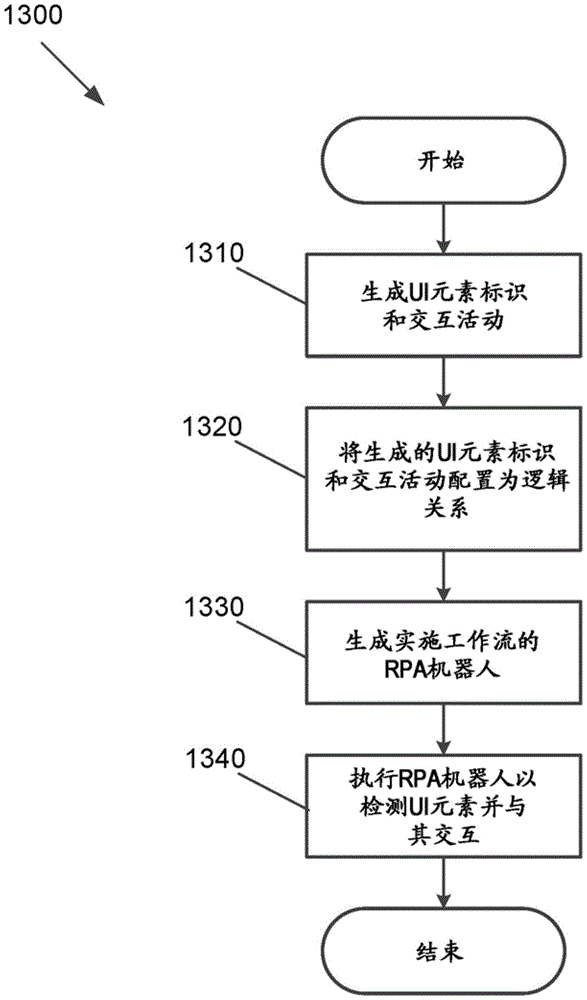
Fig. 13 is a flow chart illustrating a process 1300 for generating an RPA workflow using multiple identification techniques according to an embodiment of the invention. The flow begins by generating a UI element identification and interactivity at 1310. These activities may be one or more of a selector-based identification activity, a CV-based identification activity, a unified target identification activity, an image matching identification activity, a selector and OCR-based identification activity, any other suitable identification activity, any combination thereof, and the like.
The UI element identification and interactivity are then configured as logical relationships at 1320. The logical relationships may be sequential, conditional (e.g., if the first activity did not successfully uniquely detect the UI element, then the second, then third, etc. are used until the UI element is uniquely identified or all activities have been attempted), parallel, etc. At 1330, an RPA robot is generated that implements a workflow including UI element identification and interactivity, and at 1340, the RPA robot is executed to detect and interact with UI elements.
FIG. 14 is a flow chart illustrating a process 1400 for creating a UI object library and configuration items to work with a new version of an application in accordance with an embodiment of the invention. If one or more UI object libraries have been previously created at 1410, the flow may begin by loading one or more UI object libraries from the UI object repository. Then, at 1420, UI descriptors for interacting with the respective UI elements of the campaign are created and/or added from one or more UI object libraries to interact with the new version of the application with the changed UI.
Once the appropriate UI descriptor is updated, a UI object library including the UI descriptor is published in a UI object repository at 1430. The UI object library may also include applications, screens, and at least some UI elements from applications with which the activity interacts. However, in some embodiments, other UI elements and/or UI descriptors not specifically used in the RPA workflow may be included. The UI object library is then published or republished in the UI object repository at 1440 for use in other RPA workflows and/or by other developers.
If UI objects are missing from the UI object library or the active UI descriptor is no longer suitable for the new version of the application, the user may add these objects. The created UI object library and possibly other UI object libraries in the UI object repository may be displayed to the user in the designer application. In some embodiments, the publishing of the object library may be performed as part of a global Object Library Database (OLDB) or a local OLDB. For example, the global OLDB UI object repository may be a globally shared database (excellent center (CoE) level). The local OLDB UI object repository may be a locally shared database (local machine level). In some embodiments, the UI object library may be pushed and published to a service, such as UiPath TM Service or Go-! And (5) serving. This allows a collection of UI object libraries to be shared with the world, if desired. The storage form of the UI object repository (e.g., OLDB) should be decided at an architecture/technology level.
According to an embodiment of the invention, the flow steps performed in fig. 8-14 may be performed by a computer program encoding instructions for the processor(s) to perform at least a portion of the flow(s) described in fig. 8-14. The computer program may be embodied on a non-transitory computer readable medium. The computer readable medium may be, but is not limited to, a hard disk drive, a flash memory device, RAM, magnetic tape, and/or any other such medium or combination of media for storing data. The computer program may include encoded instructions for controlling a processor(s) of a computing system (e.g., processor(s) 510 of computing system 500 of fig. 5) to implement all or part of the flow steps described in fig. 8-14, which may also be stored on a computer-readable medium.
The computer program may be implemented in hardware, software or hybrid implementations. The computer program may be comprised of modules that are in operative communication with each other and that are designed to communicate information or instructions to a display. The computer program may be configured to run on a general purpose computer, ASIC, or any other suitable device.
It will be readily understood that the components of the various embodiments of the present invention, as generally described and illustrated in the figures herein, could be arranged and designed in a wide variety of different configurations. Thus, the detailed description of the embodiments of the invention, as illustrated in the accompanying drawings, is not intended to limit the scope of the invention, as claimed, but is merely representative of selected embodiments of the invention.
The particular features, structures, or characteristics of the invention may be combined in any suitable manner in one or more embodiments as described throughout this specification. For example, reference throughout this specification to "certain embodiments," "some embodiments," or similar language means that a particular feature, structure, or characteristic described in connection with the embodiment is included in at least one embodiment of the present invention. Thus, appearances of the phrases "in certain embodiments," "in some embodiments," "in other embodiments," or similar language throughout this specification do not necessarily all refer to the same group of embodiments, and the described features, structures, or characteristics may be combined in any suitable manner in one or more embodiments.
It should be noted that reference throughout this specification to features, advantages, or similar language does not imply that all of the features and advantages that may be realized with the present invention should be or are in any single embodiment of the invention. Rather, language referring to the features and advantages is understood to mean that a specific feature, advantage, or characteristic described in connection with an embodiment is included in at least one embodiment of the present invention. Thus, discussion of the features and advantages, and similar language, throughout this specification may, but do not necessarily, refer to the same embodiment.
Furthermore, the described features, advantages, and characteristics of the invention may be combined in any suitable manner in one or more embodiments. One skilled in the relevant art will recognize that the invention may be practiced without one or more of the specific features or advantages of a particular embodiment. In other instances, additional features and advantages may be recognized in certain embodiments that may not be present in all embodiments of the invention.
Those of ordinary skill in the art will readily appreciate that the present invention as discussed above may be implemented by different orders of steps and/or hardware elements other than the disclosed configurations. Thus, while the invention has been described based upon these preferred embodiments, certain modifications, variations, and alternative constructions will be apparent to those skilled in the art while remaining within the spirit and scope of the invention. Accordingly, for determining the scale and boundaries of the present invention, reference should be made to the appended claims.