CN116056747A - Embolic microcatheter for delivery of microspheres to peripheral vessels - Google Patents
Embolic microcatheter for delivery of microspheres to peripheral vessels Download PDFInfo
- Publication number
- CN116056747A CN116056747A CN202180058781.8A CN202180058781A CN116056747A CN 116056747 A CN116056747 A CN 116056747A CN 202180058781 A CN202180058781 A CN 202180058781A CN 116056747 A CN116056747 A CN 116056747A
- Authority
- CN
- China
- Prior art keywords
- microcatheter
- embolic
- embolic microcatheter
- distal
- section
- Prior art date
- Legal status (The legal status is an assumption and is not a legal conclusion. Google has not performed a legal analysis and makes no representation as to the accuracy of the status listed.)
- Pending
Links
Images


Classifications
-
- A—HUMAN NECESSITIES
- A61—MEDICAL OR VETERINARY SCIENCE; HYGIENE
- A61M—DEVICES FOR INTRODUCING MEDIA INTO, OR ONTO, THE BODY; DEVICES FOR TRANSDUCING BODY MEDIA OR FOR TAKING MEDIA FROM THE BODY; DEVICES FOR PRODUCING OR ENDING SLEEP OR STUPOR
- A61M25/00—Catheters; Hollow probes
- A61M25/0043—Catheters; Hollow probes characterised by structural features
- A61M25/005—Catheters; Hollow probes characterised by structural features with embedded materials for reinforcement, e.g. wires, coils, braids
- A61M25/0052—Localized reinforcement, e.g. where only a specific part of the catheter is reinforced, for rapid exchange guidewire port
-
- A—HUMAN NECESSITIES
- A61—MEDICAL OR VETERINARY SCIENCE; HYGIENE
- A61M—DEVICES FOR INTRODUCING MEDIA INTO, OR ONTO, THE BODY; DEVICES FOR TRANSDUCING BODY MEDIA OR FOR TAKING MEDIA FROM THE BODY; DEVICES FOR PRODUCING OR ENDING SLEEP OR STUPOR
- A61M25/00—Catheters; Hollow probes
- A61M25/0067—Catheters; Hollow probes characterised by the distal end, e.g. tips
-
- A—HUMAN NECESSITIES
- A61—MEDICAL OR VETERINARY SCIENCE; HYGIENE
- A61M—DEVICES FOR INTRODUCING MEDIA INTO, OR ONTO, THE BODY; DEVICES FOR TRANSDUCING BODY MEDIA OR FOR TAKING MEDIA FROM THE BODY; DEVICES FOR PRODUCING OR ENDING SLEEP OR STUPOR
- A61M25/00—Catheters; Hollow probes
- A61M25/0021—Catheters; Hollow probes characterised by the form of the tubing
- A61M25/0023—Catheters; Hollow probes characterised by the form of the tubing by the form of the lumen, e.g. cross-section, variable diameter
-
- A—HUMAN NECESSITIES
- A61—MEDICAL OR VETERINARY SCIENCE; HYGIENE
- A61M—DEVICES FOR INTRODUCING MEDIA INTO, OR ONTO, THE BODY; DEVICES FOR TRANSDUCING BODY MEDIA OR FOR TAKING MEDIA FROM THE BODY; DEVICES FOR PRODUCING OR ENDING SLEEP OR STUPOR
- A61M25/00—Catheters; Hollow probes
- A61M25/0043—Catheters; Hollow probes characterised by structural features
- A61M25/0045—Catheters; Hollow probes characterised by structural features multi-layered, e.g. coated
-
- A—HUMAN NECESSITIES
- A61—MEDICAL OR VETERINARY SCIENCE; HYGIENE
- A61M—DEVICES FOR INTRODUCING MEDIA INTO, OR ONTO, THE BODY; DEVICES FOR TRANSDUCING BODY MEDIA OR FOR TAKING MEDIA FROM THE BODY; DEVICES FOR PRODUCING OR ENDING SLEEP OR STUPOR
- A61M25/00—Catheters; Hollow probes
- A61M25/0043—Catheters; Hollow probes characterised by structural features
- A61M25/005—Catheters; Hollow probes characterised by structural features with embedded materials for reinforcement, e.g. wires, coils, braids
-
- A—HUMAN NECESSITIES
- A61—MEDICAL OR VETERINARY SCIENCE; HYGIENE
- A61M—DEVICES FOR INTRODUCING MEDIA INTO, OR ONTO, THE BODY; DEVICES FOR TRANSDUCING BODY MEDIA OR FOR TAKING MEDIA FROM THE BODY; DEVICES FOR PRODUCING OR ENDING SLEEP OR STUPOR
- A61M25/00—Catheters; Hollow probes
- A61M25/0043—Catheters; Hollow probes characterised by structural features
- A61M25/0054—Catheters; Hollow probes characterised by structural features with regions for increasing flexibility
-
- A—HUMAN NECESSITIES
- A61—MEDICAL OR VETERINARY SCIENCE; HYGIENE
- A61M—DEVICES FOR INTRODUCING MEDIA INTO, OR ONTO, THE BODY; DEVICES FOR TRANSDUCING BODY MEDIA OR FOR TAKING MEDIA FROM THE BODY; DEVICES FOR PRODUCING OR ENDING SLEEP OR STUPOR
- A61M25/00—Catheters; Hollow probes
- A61M25/0067—Catheters; Hollow probes characterised by the distal end, e.g. tips
- A61M25/0068—Static characteristics of the catheter tip, e.g. shape, atraumatic tip, curved tip or tip structure
- A61M25/007—Side holes, e.g. their profiles or arrangements; Provisions to keep side holes unblocked
-
- A—HUMAN NECESSITIES
- A61—MEDICAL OR VETERINARY SCIENCE; HYGIENE
- A61M—DEVICES FOR INTRODUCING MEDIA INTO, OR ONTO, THE BODY; DEVICES FOR TRANSDUCING BODY MEDIA OR FOR TAKING MEDIA FROM THE BODY; DEVICES FOR PRODUCING OR ENDING SLEEP OR STUPOR
- A61M25/00—Catheters; Hollow probes
- A61M25/01—Introducing, guiding, advancing, emplacing or holding catheters
- A61M25/0105—Steering means as part of the catheter or advancing means; Markers for positioning
- A61M25/0108—Steering means as part of the catheter or advancing means; Markers for positioning using radio-opaque or ultrasound markers
-
- A—HUMAN NECESSITIES
- A61—MEDICAL OR VETERINARY SCIENCE; HYGIENE
- A61B—DIAGNOSIS; SURGERY; IDENTIFICATION
- A61B17/00—Surgical instruments, devices or methods, e.g. tourniquets
- A61B17/12—Surgical instruments, devices or methods, e.g. tourniquets for ligaturing or otherwise compressing tubular parts of the body, e.g. blood vessels, umbilical cord
- A61B17/12022—Occluding by internal devices, e.g. balloons or releasable wires
- A61B17/12099—Occluding by internal devices, e.g. balloons or releasable wires characterised by the location of the occluder
- A61B17/12109—Occluding by internal devices, e.g. balloons or releasable wires characterised by the location of the occluder in a blood vessel
-
- A—HUMAN NECESSITIES
- A61—MEDICAL OR VETERINARY SCIENCE; HYGIENE
- A61B—DIAGNOSIS; SURGERY; IDENTIFICATION
- A61B17/00—Surgical instruments, devices or methods, e.g. tourniquets
- A61B17/12—Surgical instruments, devices or methods, e.g. tourniquets for ligaturing or otherwise compressing tubular parts of the body, e.g. blood vessels, umbilical cord
- A61B17/12022—Occluding by internal devices, e.g. balloons or releasable wires
- A61B17/12131—Occluding by internal devices, e.g. balloons or releasable wires characterised by the type of occluding device
- A61B17/12181—Occluding by internal devices, e.g. balloons or releasable wires characterised by the type of occluding device formed by fluidized, gelatinous or cellular remodelable materials, e.g. embolic liquids, foams or extracellular matrices
- A61B17/12186—Occluding by internal devices, e.g. balloons or releasable wires characterised by the type of occluding device formed by fluidized, gelatinous or cellular remodelable materials, e.g. embolic liquids, foams or extracellular matrices liquid materials adapted to be injected
-
- A—HUMAN NECESSITIES
- A61—MEDICAL OR VETERINARY SCIENCE; HYGIENE
- A61B—DIAGNOSIS; SURGERY; IDENTIFICATION
- A61B17/00—Surgical instruments, devices or methods, e.g. tourniquets
- A61B17/12—Surgical instruments, devices or methods, e.g. tourniquets for ligaturing or otherwise compressing tubular parts of the body, e.g. blood vessels, umbilical cord
- A61B17/12022—Occluding by internal devices, e.g. balloons or releasable wires
- A61B2017/1205—Introduction devices
-
- A—HUMAN NECESSITIES
- A61—MEDICAL OR VETERINARY SCIENCE; HYGIENE
- A61M—DEVICES FOR INTRODUCING MEDIA INTO, OR ONTO, THE BODY; DEVICES FOR TRANSDUCING BODY MEDIA OR FOR TAKING MEDIA FROM THE BODY; DEVICES FOR PRODUCING OR ENDING SLEEP OR STUPOR
- A61M25/00—Catheters; Hollow probes
- A61M25/0021—Catheters; Hollow probes characterised by the form of the tubing
- A61M2025/0042—Microcatheters, cannula or the like having outside diameters around 1 mm or less
-
- A—HUMAN NECESSITIES
- A61—MEDICAL OR VETERINARY SCIENCE; HYGIENE
- A61M—DEVICES FOR INTRODUCING MEDIA INTO, OR ONTO, THE BODY; DEVICES FOR TRANSDUCING BODY MEDIA OR FOR TAKING MEDIA FROM THE BODY; DEVICES FOR PRODUCING OR ENDING SLEEP OR STUPOR
- A61M25/00—Catheters; Hollow probes
- A61M25/0043—Catheters; Hollow probes characterised by structural features
- A61M2025/0059—Catheters; Hollow probes characterised by structural features having means for preventing the catheter, sheath or lumens from collapsing due to outer forces, e.g. compressing forces, or caused by twisting or kinking
-
- A—HUMAN NECESSITIES
- A61—MEDICAL OR VETERINARY SCIENCE; HYGIENE
- A61M—DEVICES FOR INTRODUCING MEDIA INTO, OR ONTO, THE BODY; DEVICES FOR TRANSDUCING BODY MEDIA OR FOR TAKING MEDIA FROM THE BODY; DEVICES FOR PRODUCING OR ENDING SLEEP OR STUPOR
- A61M25/00—Catheters; Hollow probes
- A61M25/0067—Catheters; Hollow probes characterised by the distal end, e.g. tips
- A61M25/008—Strength or flexibility characteristics of the catheter tip
- A61M2025/0081—Soft tip
-
- A—HUMAN NECESSITIES
- A61—MEDICAL OR VETERINARY SCIENCE; HYGIENE
- A61M—DEVICES FOR INTRODUCING MEDIA INTO, OR ONTO, THE BODY; DEVICES FOR TRANSDUCING BODY MEDIA OR FOR TAKING MEDIA FROM THE BODY; DEVICES FOR PRODUCING OR ENDING SLEEP OR STUPOR
- A61M2205/00—General characteristics of the apparatus
- A61M2205/75—General characteristics of the apparatus with filters
- A61M2205/7545—General characteristics of the apparatus with filters for solid matter, e.g. microaggregates
-
- A—HUMAN NECESSITIES
- A61—MEDICAL OR VETERINARY SCIENCE; HYGIENE
- A61M—DEVICES FOR INTRODUCING MEDIA INTO, OR ONTO, THE BODY; DEVICES FOR TRANSDUCING BODY MEDIA OR FOR TAKING MEDIA FROM THE BODY; DEVICES FOR PRODUCING OR ENDING SLEEP OR STUPOR
- A61M25/00—Catheters; Hollow probes
- A61M25/0043—Catheters; Hollow probes characterised by structural features
- A61M25/005—Catheters; Hollow probes characterised by structural features with embedded materials for reinforcement, e.g. wires, coils, braids
- A61M25/0053—Catheters; Hollow probes characterised by structural features with embedded materials for reinforcement, e.g. wires, coils, braids having a variable stiffness along the longitudinal axis, e.g. by varying the pitch of the coil or braid
Landscapes
- Health & Medical Sciences (AREA)
- Life Sciences & Earth Sciences (AREA)
- Animal Behavior & Ethology (AREA)
- Veterinary Medicine (AREA)
- Public Health (AREA)
- Engineering & Computer Science (AREA)
- Biomedical Technology (AREA)
- Heart & Thoracic Surgery (AREA)
- General Health & Medical Sciences (AREA)
- Anesthesiology (AREA)
- Hematology (AREA)
- Pulmonology (AREA)
- Biophysics (AREA)
- Media Introduction/Drainage Providing Device (AREA)
- Surgery (AREA)
- Surgical Instruments (AREA)
- Reproductive Health (AREA)
- Vascular Medicine (AREA)
- Nuclear Medicine, Radiotherapy & Molecular Imaging (AREA)
- Medical Informatics (AREA)
- Molecular Biology (AREA)
- Medicines That Contain Protein Lipid Enzymes And Other Medicines (AREA)
Abstract
An embolic microcatheter for peripheral arterial embolization comprising an elongate tubular member comprising a distal end having a length of 150-500mm and an outer diameter of less than 0.8mm, wherein the elongate tubular member comprises a plurality of sections, each section having a length of 5-150 mm, wherein the wall of each of the plurality of sections comprises a braid, a polymer formed about the braid, and a liner covering the inner surface thereof; wherein the polymers of the plurality of segments are different; and the embolic microcatheter includes a distal tip having a length of 1mm-3mm and extending between the proximal end of the first radiopaque marker of the elongate tubular member and the distal opening of the elongate tubular member; the wall of the distal tip is free of braid.
Description
Technical Field
The present disclosure relates generally to the field of embolic microcatheters, and in particular to embolic catheters suitable for delivering embolic microspheres to peripheral blood vessels.
Background
Arterial embolization therapy, tumor embolization, or transcatheter arterial embolization (Transcatheter Arterial Embolization, TAE) involves the direct administration of embolic material (which may include chemotherapy or/and radiation therapy) to a tumor (e.g., a liver tumor) via a microcatheter.
Embolization of tumors is often performed using microcatheters because of the need to selectively affect the tumor while preventing damage to healthy tissue as much as possible. The main problem associated with embolization is "non-target embolization", wherein embolic material travels to blood vessels other than those that directly feed the target tumor or target tumor area, thus damaging healthy tissue, leading to uncomfortable and even dangerous results.
During embolization, particularly peripheral vascular embolization, the embolic catheter must be advanced through small and often tortuous vessels. These vessels are difficult, if not impossible, to access using large and/or hard microcatheters. Moreover, the vessels in the body often spasm during manipulation, resulting in ineffective embolic material delivery, and therefore flexible micro-sized catheters are absolutely necessary.
The main disadvantage of transcatheter embolization is that embolic material, which is not normally visible, may reflux and reach non-target tissues and cause damage to them. Furthermore, reflux of embolic material may negatively affect delivery of embolic material to the target tissue, and thus impair the therapeutic effect and its clinical outcome.
The inventors of the present application have disclosed microcatheters having a filtration section for delivering embolic microspheres while preventing backflow of the microspheres. However, there remains a need for microcatheters capable of delivering embolic microspheres to peripheral blood vessels, i.e., microcatheters having an outer diameter small enough to allow unimpeded access to the peripheral blood vessel without causing the microcatheter to become occluded or kinked.
Disclosure of Invention
The present disclosure relates to embolic microcatheters suitable for traversing and/or reaching peripheral arteries (typically 1.7 or 1.9French (Fr)), while also facilitating unobstructed delivery of embolic microspheres.
This is advantageously achieved by the unique structure of the wall of the embolic microcatheter, which has an outer diameter of less than 0.8mm, but is still trackable and torque resistant. The vast majority of the wall is made of a braid, a polymer formed around the braid, and a liner covering the inner surface of the wall. The distal tip of the microcatheter (approximately the last 1mm-1.5 mm) includes radiopaque markers for positioning. The distal tip is also characterized by its wall being free of braid. This may advantageously compensate for the increased wall thickness caused by the radiopaque marker, according to some embodiments.
The embolic microcatheter disclosed herein further comprises a filtration section having a plurality of openings configured for fluid outflow while preventing microsphere outflow, thereby providing focused delivery of embolic microspheres through the distal opening of the microcatheter while ensuring minimal backflow. Advantageously, the size, shape and distribution of the openings allow for smooth delivery of the microspheres despite the small diameter of the microcatheter. According to some embodiments, the plurality of side openings are distributed in at least five circumferential rings spaced apart from each other by 100 micrometers to 200 micrometers.
According to some embodiments, the wall of the tubular member comprises a plurality of sections, each section having a length of 5mm-150mm, and each section being formed of a different polymer. This may advantageously provide pushability on the one hand and efficient steering through tortuous vessels on the other hand.
According to some embodiments, there is provided an embolic microcatheter for embolizing a peripheral artery, comprising: an elongate tubular member comprising a distal end extending from a proximal marker to a distal end opening, the distal end having an outer diameter of about 0.7mm or less, wherein the elongate tubular member comprises a plurality of sections, each section having a length of 5mm-120mm, wherein a wall of each of the plurality of sections comprises a braid, a polymer formed around the braid, and a liner covering an inner surface thereof; wherein the polymers of at least some of the plurality of segments are different, and wherein the wall has a thickness of less than 100 microns; a distal tip having a length of 0.5mm-3mm and extending between a proximal end of the distal radiopaque marker of the elongate tubular member and a distal opening of the elongate tubular member; wherein the wall of the distal tip is free of braid.
According to some embodiments, the lumen of the distal end is in the range of 0.3mm-0.7 mm. According to some embodiments, the lumen of the distal end is in the range of 0.35mm-0.55 mm. According to some embodiments, the lumen of the distal tip is less than 0.5mm.
According to some embodiments, the wall thickness is less than 90 microns.
According to some embodiments, the braid may be made of tungsten wire. According to some embodiments, the braid is made of wires having a diameter of 15-20 microns. According to some embodiments, the braid has 150-220 Picks Per Inch (PPI).
According to some embodiments, the plurality of segments comprises at least 5 segments. According to some embodiments, the plurality of sections includes at least 9 sections. According to some embodiments, the most distal section of the plurality of sections has a length of 5-15 mm.
According to some embodiments, the embolic microcatheter further comprises a distal radiopaque marker, wherein the distal radiopaque marker comprises a metallic marker band.
According to some embodiments, the most distal one of the plurality of segments comprises a filter formed in a wall of the elongate tubular member, the filter comprising a plurality of side openings distributed in at least 5 circumferential rings spaced from each other by 100 to 200 microns.
According to some embodiments, the plurality of openings are in the form of axial slits. According to some embodiments, the axial slit has a length of about 100-150 microns and a height of about 20-40 microns.
According to some embodiments, the outermost circumferential ring of the circumferential rings of the outermost filter segments is positioned proximally about 2-6mm from the distal opening.
According to some embodiments, the plurality of side openings are distributed in at least 8 circumferential circles. According to some embodiments, each of these circumferential rings comprises 4-8 axial slits. According to some embodiments, the nearest of the at least 5 circumferential turns comprises fewer side openings than its distal turn. According to some embodiments, the nearest circumferential ring comprises 1-3 side openings. According to some embodiments, the side openings of the nearest circumferential section are circumferentially displaced relative to the side openings in its adjacent circumferential section.
According to some embodiments, there is provided an elongate tubular member terminating in a distal opening, the elongate tubular member comprising: a distal end extending from the distal opening 200-500mm toward the proximal end of the elongate tubular member, wherein the outer diameter of the elongate tubular member is less than 0.8mm, wherein the elongate tubular member comprises a plurality of sections, each section having a length of 5-150 mm, wherein the wall of each of the plurality of sections comprises a braid, a polymer formed about the braid, and a liner covering an inner surface thereof; wherein the polymer of the plurality of segments is different, wherein the wall has a thickness of less than 100 microns, and wherein the braid is made of wires having a diameter of 15-18 microns and has a Pick Per Inch (PPI) of 200-350.
According to some embodiments, the lumen of the distal end is in the range of 0.35mm-0.6 mm. According to some embodiments, the outer diameter of the distal end of the elongate tubular member is less than 0.75mm.
According to some embodiments, the wall thickness is less than 90 microns.
According to some embodiments, the braid may be made of tungsten wire.
According to some embodiments, the plurality of segments comprises at least 5 segments. According to some embodiments, the plurality of sections includes at least 9 sections. According to some embodiments, the most distal section of the plurality of sections has a length of 10-20 mm.
According to some embodiments, the embolic microcatheter further comprises a radiopaque marker. According to some embodiments, the radiopaque marker comprises a metallic marker band.
According to some embodiments, the most distal one of the plurality of segments comprises a filter formed in a wall of the elongate tubular member, the filter comprising a plurality of side openings distributed in at least 5 circumferential rings spaced from each other by 100 to 200 microns.
According to some embodiments, the plurality of openings are in the form of axial slits. According to some embodiments, the axial slit has a length of about 100-150 microns and a height of about 20-40 microns.
According to some embodiments, the outermost circumferential ring of the circumferential rings of the outermost filter segments is positioned proximally about 2-6mm from the distal opening.
According to some embodiments, the plurality of side openings are distributed in at least 8 circumferential circles. According to some embodiments, each of these circumferential rings comprises 4-8 axial slits.
According to some embodiments, the nearest of the at least 5 circumferential turns comprises fewer side openings than its distal turn. According to some embodiments, the nearest circumferential ring comprises 1-3 side openings. According to some embodiments, the side openings of the nearest circumferential section are circumferentially displaced relative to the side openings in its adjacent circumferential section.
Some embodiments of the present disclosure may include some, all, or none of the above features. One or more technical advantages may be readily apparent to one skilled in the art from the figures, descriptions, and claims included herein. Furthermore, while specific features have been enumerated above, various embodiments may include all, some, or none of the enumerated features.
In addition to the exemplary aspects and embodiments described above, other aspects and embodiments will be further expanded in the drawings and the following detailed description.
Drawings
The features, nature, and advantages of the present disclosure will become more apparent from the detailed description set forth below when taken in conjunction with the drawings in which like reference characters identify correspondingly throughout. The same structures, elements or portions appearing in more than one figure are generally labeled with the same number throughout all of the figures in which they appear. Alternatively, elements or portions appearing in more than one figure may be labeled with different numbers in different figures in which they appear. The dimensions of the components and features in the figures are chosen for convenience and clarity of presentation and are not necessarily shown to scale. These figures are listed below.
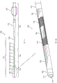
Fig. 1A schematically illustrates a microcatheter including an outer layer including multiple sections made of different polymeric materials according to some embodiments.
Fig. 1B schematically illustrates a perspective cross-sectional view of the distal end of the microcatheter of fig. 1A, illustrating an outer layer, an strike layer, an inner layer, and a woven scaffold between the inner and outer layers.
Fig. 2A schematically illustrates an embolic microcatheter with a fluid barrier forming section according to some embodiments.
Fig. 2B schematically illustrates an enlarged and partially exposed view of the distal end of the microcatheter of fig. 2A, in accordance with some embodiments.
Fig. 2C schematically illustrates an enlarged and partially exposed view of the distal tip of the microcatheter of fig. 2A, in accordance with some embodiments.
Fig. 2D schematically illustrates a slit formed by selectively cutting through a wall of a fluid barrier forming section, such as cutting through the fluid barrier forming section of the embolic microcatheter of fig. 2A, in accordance with some embodiments.
Fig. 3 schematically illustrates an alternative slit pattern of an embolic microcatheter (e.g., the embolic microcatheter of fig. 2A) according to some embodiments.
Fig. 4 schematically illustrates another alternative slit pattern of an embolic microcatheter (e.g., the embolic microcatheter of fig. 2A) according to some embodiments.
Detailed Description
The detailed description set forth below in connection with the appended drawings is intended as a description of various configurations and is not intended to represent the only configurations in which the concepts described herein may be practiced. The detailed description includes specific details for the purpose of providing a thorough understanding of the various concepts. It will be apparent, however, to one skilled in the art that these concepts may be practiced without the specific details presented herein. In some instances, well-known features may be omitted or simplified in order not to obscure the present disclosure.
One of the major challenges of embolic microcatheters is to ensure that the outer diameter is small enough to facilitate access to the peripheral blood vessel, while also ensuring that delivery of embolic microspheres is not impeded (including flow within the lumen of the microcatheter is not impeded) and that the catheter wall is strong, traceable, and kink resistant.
Advantageously, these requirements are met by the structural features of the microcatheters and tubular walls thereof disclosed herein.
Referring now to fig. 1A and 1B, an enlarged/exposed view of an embolic microcatheter 100 and its distal portion is schematically illustrated.
As used herein, the terms "embolization," "transcatheter arterial embolization," and "TAE" are used interchangeably, and refer to the passage and residence of emboli within the blood stream for therapeutic purposes (e.g., as hemostatic treatment of bleeding or as treatment of certain types of cancer by intentionally blocking blood vessels to starve tumor cells).
The seat 102 is configured to allow access to the lumen of the elongate tubular member 110 for various functions, such as injecting fluids or medications, or introducing a guidewire. The seat 102 optionally includes a strain relief device 112 that is preferably mechanically coupled to the seat 102. The strain relief device 112 may be made of a polymeric material and, as shown, may be tapered at its distal end. The strain relief device 112 may be configured to provide structural support to the elongate tubular member 110 to prevent kinking thereof.
According to some embodiments, the wall of the elongate tubular member 110 may comprise a plurality of sections, each featuring the polymer used. According to some embodiments, the plurality of segments may include 3, 4, 5, 6, 7, 8, 9, 10, 15, 20, or more segments. Each possibility is a separate embodiment.
According to some embodiments, different polymer layers may contribute to different characteristics of the layers/segments and thus the elongate tubular member 110. For example, the different polymer layers may contribute to the elasticity, flexibility, stretchability, strength, hardness, stiffness, ultimate tensile strength, elongation or any other characteristic of the layers and thus of the microcatheter. Each possibility is a separate embodiment.
The proximal end 130 of the elongate tubular member 110 is attached to the strain relief device 112, including a first section 132. The outer layer of section 132 may be made of a polymeric material having a relatively high hardness, such as a polyether block amide having a shore hardness of about 70D and/or a flexural modulus of about 74,000 psi. According to some embodiments, the proximal end 132 may have a length of 600-1300mm (e.g., about 1000 mm).
Optionally, a portion of the section 132 may include a heat shrink material 134 covering the junction between the strain relief device 112 and the elongate tubular member 110.
The adjacent section 132 is a second section and the section 136 is slightly softer. The outer layer of section 132 may be made of a polymeric material having a shore hardness of about 60D-70D and/or a flexural modulus between 41,000psi and 74,000 psi. The length of section 136 may be 10-40mm, or 20-30mm, such as 25mm. Following the section 136 may be a slightly softer section 138, which may be made of a polymeric material having a shore hardness of about 60-65D and/or a flexural modulus of about 41,000 psi. The length of section 138 may be 60-80mm, for example 70mm.
According to some embodiments, the polymeric material of section 138 is softer than the polymeric material of section 136. According to some embodiments, the polymeric material of section 136 is softer than the polymeric material of section 132.
The intermediate portion 140 of the elongate tubular member 110 comprises: a section 142 having an outer layer that may be made from polyether block amide or other suitable polymer having a 55D shore hardness and/or a flexural modulus of about 25,000 psi; a section 144 having an outer layer made of a polymeric material having a shore hardness of about 55D (e.g., a polycarbonate-based thermoplastic polyurethane having a shore hardness of about 50D); a section 146 having an outer layer having one or more polycarbonate-based thermoplastic polyurethanes between 55D shore hardness and 95A shore hardness; a section 148 having an outer layer made of one or more polycarbonate-based thermoplastic polyurethanes having a shore hardness of 95A. The length of section 142 may be 50-90mm, for example 70mm. The length of the section 144 may be 80-1100mm (e.g., about 90 mm). The length of section 146 may be 50-70mm (e.g., about 65 mm). The length of section 148 may be 5-30mm (e.g., about 15 mm).
According to some embodiments, the polymeric material of section 148 is softer than the polymeric material of section 146. According to some embodiments, the polymeric material of section 146 is softer than the polymeric material of section 144. According to some embodiments, the polymeric material of section 144 is softer than the polymeric material of section 142.
The distal end 150 of the elongate tubular member 110 includes: a section 152 having an outer layer made of a polymeric material having a shore hardness of about 95A, such as a polycarbonate-based thermoplastic polyurethane having a shore hardness of 95A and a length of 10-40mm (e.g., about 25 mm); a section 154 having an outer layer made of a polymeric material having a shore hardness of about 85A, such as a polycarbonate-based thermoplastic polyurethane having a shore hardness of 85A and a length of 3-10mm (e.g., about 6 mm). The polymer of section 154 further includes a polymer marker such as, but not limited to, tantalum powder; segment 156 has an outer layer made of a polymeric material having a shore hardness of about 80A, such as a polycarbonate-based thermoplastic polyurethane having a shore hardness of about 85A and a length of about 5-15mm (e.g., about 9.5 mm).
According to some embodiments, the elongate tubular member 110 may have an outer diameter in the range of 0.5mm-1.5mm or in the range of 0.55mm-1.0 mm. According to some embodiments, the outer diameter of tubular member 110 may vary from its proximal end to its distal end. According to some embodiments, the outer diameter of tubular member 110 may taper from its proximal end to its distal end.
According to some embodiments, the outer diameter of the proximal end of tubular member 110, including section 132, may be in the range of 0.8-1.0mm, such as, but not limited to, about 0.95mm. According to some embodiments, the outer diameter of the middle section of tubular member 110 may be in the range of 0.7-0.9 mm. According to some embodiments, the outer diameter of the tubular member may decrease distally from about 0.9mm to about 0.7mm. According to some embodiments, the outer diameter of the distal end of tubular member 110 may be in the range of 0.5-0.75 mm. According to some embodiments, the outer diameter of the tubular member may decrease from about 0.75mm to about 0.55mm toward the distal opening. According to some embodiments, the outer diameter of the distal tip 170 may be in the range of 0.55-0.65 mm. According to some embodiments, the outer diameter of the distal tip 170 may be 0.56mm along its entire length, except that the outer diameter on the marker band 162 may be about 0.6-0.65mm.
According to some embodiments, the outer diameter of section 156 is smaller than the outer diameter of section 154. According to some embodiments, the outer diameter of section 154 is smaller than the outer diameter of section 152. According to some embodiments, the outer diameter of section 152 is smaller than the outer diameter of section 148. According to some embodiments, the outer diameters of sections 148 and 146 are smaller than the outer diameter of section 144. According to some embodiments, the outer diameter of section 144 is smaller than the outer diameter of section 142. According to some embodiments, the outer diameter of section 142 is smaller than the outer diameters of sections 136 and 132.
According to some embodiments, the outer diameter is substantially constant along the same section.
According to some embodiments, the inner diameter of the elongate tubular member 110 may be in the range of 0.35-0.65mm or 0.4-0.60 mm. According to some embodiments, the inner diameter at the proximal end may be greater than the inner diameter at the distal end. According to some embodiments, the inner diameter of the elongate tubular member 110 may be about 0.55mm along the entire length of the elongate tubular member 110, and the inner diameter of the distal tip may be about 0.35-0.50mm (e.g., about 0.42 mm) except for the distal tip 170 (including the last about 5-15mm, e.g., the last 10mm, of the microcatheter). According to some embodiments, the section extending from the distal tip 170 may be tapered to about 60-90mm (e.g., about 70 mm) proximally therefrom.
As used herein, the term "distal opening" refers to the end opening of a microcatheter that opens into its lumen. According to some embodiments, distal opening 180 defines the tip of a microcatheter. According to some embodiments, the inner diameter of the distal opening 180 may be substantially equal to the inner diameter of the microcatheter lumen. According to some embodiments, the inner diameter of distal opening 180 may be smaller than the inner diameter of the microcatheter lumen, resulting in the lumen narrowing toward its end.
The distal end 150 of the elongate tubular member 110 may include a proximal marker 160 and a distal marker 162 (see also fig. 1B). According to some embodiments, the proximal marker 160 may be a radiopaque powder embedded in the outer layer, as described above with respect to the section 154. According to some embodiments, the proximal marker 160 may be positioned about 5-20mm or 10-15mm from the distal opening 180. According to some embodiments, the distal marker 162 may be a radiopaque alloy immersed in the distal tip 170. According to some embodiments, the distal marker 162 may be positioned proximally from the distal opening 180 by about 0.25-1mm.
Referring now to fig. 1B, a perspective cross-sectional view of a distal portion of the distal end 150 of the microcatheter 100 shown in fig. 1A is schematically illustrated, extending from the proximal marker 160 to the distal opening 180. As seen from this exploded view, underlying outer layer 155 is braid 190.
According to some embodiments, braid 190 extends along the entire length of shaft elongate tubular member 110. Alternatively, the braid 190 extends along the entire length of the elongate tubular member 110, spaced apart from the distal tip 170. According to some embodiments, braid 190 may extend from the proximal end of tubular member 110 up to distal marker 162. According to some embodiments, the portion of tubular member 110 extending from distal marker 162 to distal opening 180 may be devoid of braid.
Preferably, the braid 190 has a certain number of Picks Per Inch (PPI), ensuring that in combination with a low durometer polymer, a flexible distal end is obtained, and in combination with a polymer having a higher durometer, a relatively stiff proximal end is provided.
According to some embodiments, braid 190 may be made from multiple strands.
As used herein, the terms "braid" and "braid scaffold" may refer to structural elements, such as tubular elements formed from a plurality of interwoven wires. According to some embodiments, the braid may be formed from at least three interwoven wires forming a tube. According to some embodiments, the braid may include 8 to 48 wires or 12 to 32 wires. Each possibility is a separate embodiment. As a non-limiting example, the braid may include 16 wires.
According to some embodiments, the diameter of the wires forming the braid may be in the range of 10-40 microns, such as in the range of 12-20 microns or 15-18 microns, or any other suitable diameter in the range of 10-60 microns. Each possibility is a separate embodiment. As a non-limiting example, the wire forming the braid may have a diameter of 18 microns.
According to some embodiments, the braid may be made of tungsten, stainless steel, nickel titanium (also known as Nitinol), nitinol, cobalt chromium, platinum iridium, nylon, or any combination thereof. Each possibility is a separate embodiment. As a non-limiting example, the wire may be a tungsten wire.
According to some embodiments, at least some of the wires forming the woven skeleton may be woven in the same or opposite directions, i.e. left/right. Advantageously, the braided structure allows for good torque capacity (over the coiled framework), low flexural rigidity (i.e., good flexibility), good pushability (over the coiled framework), and excellent kink resistance.
According to some embodiments, at least some of the wires forming the woven skeleton may be non-circular/non-circular.
According to some embodiments, the woven scaffold may have a thread arrangement of 100-400 weft yarns (PPI), 150-375PPI, or 200-350PPI per inch. Each possibility is a separate embodiment. As a non-limiting example, the braided framework may have a wire arrangement of about 250 PPI. As a non-limiting example, the braided framework may have a wire arrangement of about 275 PPI. As a non-limiting example, the braided framework may have a wire arrangement of about 300 PPI. As a non-limiting example, the braided skeleton may have a wire arrangement of about 325 PPI. As a non-limiting example, the braided skeleton may have a wire arrangement of about 350 PPI. Those skilled in the art will appreciate that the term "weft yarn per inch (PPI)" is a measure of the braid density and represents the number of weft yarns (e.g., picks) per inch of the braid.
According to some embodiments, the PPI of the braid may vary along the length of the tubular member 110. According to some embodiments, the PPI at the distal tip is higher than the PPI at its distal section. As a non-limiting example, the PPI of the braid 190 at the distal tip may be about 200PPI, while the PPI of the proximal section thereof may be about 160PPI. According to some embodiments, the braid 190 includes a transition region where the PPI of the braid is 200PPI to 160PPI.
Below the braid 190 is a liner 192, which may be made of Polytetrafluoroethylene (PTFE). According to some embodiments, the liner 192 may have a thickness of 5-25 microns or 5-15 microns. Each possibility is a separate embodiment. According to some embodiments, the liner may be a ram-extruded liner.
According to some embodiments, the total thickness of the wall of the distal end of the elongate tubular member is no more than about 100 microns. According to some embodiments, the total thickness of the wall of the distal end of the elongate tubular member is no more than about 90 microns. According to some embodiments, the total thickness of the wall of the distal end of the elongate tubular member is no more than about 80 microns.
Referring now to fig. 2A-2D, enlarged/exposed views of embolic microcatheter 200 and portions thereof are schematically illustrated. Embolic microcatheter 200 may be similar to embolic microcatheter 100, except that embolic microcatheter 200 also includes a filter 220.
The proximal end of microcatheter 200 includes a hub 202 that is molded over or otherwise attached to microcatheter 200. The hub 202 is configured to allow access to the lumen of the microcatheter 100 for various functions, such as injecting fluids or drugs, or introducing a guidewire. The seat 202 includes a strain relief device 212 that is preferably mechanically coupled to the seat 202. The strain relief device 212 may be made of a polymeric material and, as shown, may be tapered at its distal end. The strain relief device 212 is configured to provide structural support to the microcatheter 200, thereby preventing/minimizing kinking of the microcatheter 200.
Referring now to fig. 2B, a partially exposed view of the distal end 250 of the illustrated microcatheter 200 (partially exposed distal end 250 extending between proximal marker 260 and distal marker 262) is schematically illustrated. Similar to elongate tubular member 110, underlying the outer layer is braid 290, which is substantially identical to braid 190.
The filter 220 includes a plurality of penetrating side openings formed in the wall of the elongate tubular member 210, schematically illustrated in fig. 2B.
As used herein, the term "plurality" when used in conjunction with a side opening refers to 2 or more, 3 or more, 5 or more, 10 or more, 15 or more, 20 or more, or 25 or more axial slits. Each possibility is a separate embodiment.
According to some embodiments, the filter 220 may be an integral part of the elongate tubular member 110 and may extend along a length of 0.3mm to 20mm, such as along 1mm to 10mm, 1mm to 5mm, 1.5mm to 5mm, 2mm to 5mm, or any other suitable length. Each possibility is a separate embodiment.
According to some embodiments, the total opening area of filter 220 formed by the side openings may be in the range of 0.2-1mm 2 、0.2-0.6mm 2 、0.3-1mm 2 、0.3-0.5mm 2 、0.4-0.6mm 2 、0.5-1.5mm 2 、1.0-3.5mm 2 、1.5-4mm 2 、2.0-3.5mm 2 In the range of 0.1-4mm 2 Any other suitable area within the scope of (c). Each possibility is a separate embodiment. According to some embodiments, at least 5%, at least 10%, at least 15% of the filter 220 is the open area formed by the side openings. According to some embodiments, 5% -30%, at least 7% -25%, 7% -20%, 5% -15% of the filter 220 is the open area formed by the side openings. Each possibility is a separate embodiment.
According to some embodiments, side openings 225 may be formed by selective cutting (e.g., selective laser cutting), i.e., without cutting the wire forming braid 290, as shown in fig. 2D. According to some embodiments, the portion of the liner below the line remains intact. According to some embodiments, when the slit is formed, both the polymer layer and the liner between the threads of braid 290 are penetrated. Advantageously, the selective cutting of the polymer layer (leaving braid 290 substantially intact) may subdivide at least some of the side openings into two or more sub-side openings (illustratively depicted as side openings 225a and 292 b) separated by the braid but not by the polymer outer layer.
Fig. 3 provides an alternative configuration of filter 220. According to some embodiments, the structure is suitable for a 1.9Fr embolic microcatheter. As seen in fig. 3, the filter 220 may include three filter sections, each comprising a plurality of side openings 225 distributed in a circumferential ring around the elongated filter 220.
According to some embodiments, the filter section 1 may comprise 1-10 turns, or 2-8 turns or 4-7 turns (here illustrated as 7 turns). According to some embodiments, each turn may include 1-8 side openings or 2-6 side openings, such as, but not limited to, 6 side openings per turn. According to some embodiments, the filter section 221 may include a total of 20-50 or 25-60 side openings, such as, but not limited to, 42 side openings. According to some embodiments, the furthest of the turns of the filter section 1 may be positioned about 3-10mm or 4-8mm, such as, but not limited to, about 5mm, from the distal opening 180.
According to some embodiments, the filter section 2 may include 1-5 turns or 2-4 turns of side openings, such as, but not limited to, 3 turns of side openings. According to some embodiments, each turn may include 1-6 side openings or 2-4 side openings, such as, but not limited to, 4 side openings per turn. According to some embodiments, the filter section 2 may include a total of 5-20, 6-16 side openings, such as, but not limited to, 12 side openings.
According to some embodiments, the side openings of the filter section 2 may be circumferentially offset with respect to the side openings of the filter section 1.
According to some embodiments, the filter section 3 may comprise 1-5 turns or 2-4 turns of side openings, such as, but not limited to, 2 turns of side openings. According to some embodiments, each turn may include 1-4 side openings or 1-3 side openings, such as, but not limited to, 2 side openings per turn. According to some embodiments, the filter section 3 may comprise a total of 2-6, or 2-4 side openings, such as, but not limited to, 4 side openings.
According to some embodiments, the side openings of the first turn in the section 3 are circumferentially displaceable relative to the side openings of the second turn in the section 3. According to some embodiments, the side openings of the filter section 3 may be circumferentially offset with respect to the side openings of the filter section 1.
According to some embodiments, the side openings 225 may have dimensions of about 150 x 25 microns, about 150 x 30 microns, about 125 x 30 microns, or about 100 x 30 microns.
According to some embodiments, each turn of the side opening of the filter section 1-3 may be spaced apart from its adjacent turn by 100-200 microns or 120-180 microns, such as, but not limited to, 150 microns.
Advantageously, filter 220 may be formed by selectively cutting the polymer layer (leaving braid 290 intact). According to some embodiments, at least some of the side openings 225 may include sub-side openings (e.g., sub-side openings 225a and 225b in fig. 2D) that are separated by braid 290 rather than by a polymeric outer layer.
According to some embodiments, the slits may be positioned at the same or different longitudinal positions. Each possibility is a separate embodiment. According to some embodiments, the distribution of slits may be staggered, zigzagged, or any other suitable uniform or non-uniform distribution.
Advantageously, the filter 220 may be configured for kink-free bending despite having a plurality of side openings formed in its wall. According to some embodiments, the flexibility of filter 220 is determined by the number of side openings, the minimum cross-sectional dimension of the side openings, the width of the side openings, the length spacing, the geometry, the distance from the distal outlet, etc. (as substantially described herein), which may be achieved without kinking.
As used herein, the term "kink-free bend" may refer to a bend of the filter 220 that impedes the passage of fluid therethrough. According to some embodiments, the filter 220 may be configured for kink-free bending at an angle of about 180 degrees. According to some embodiments, the filter 220 may be configured for kink-free bending at a minimum bending radius in the range of about 0.5mm to 1.5mm, such as 0.5mm to 1.2mm, 0.5mm to 1mm, or any radius therebetween.
Advantageously, microcatheter 200 including filter 220 is effective in preventing flashback, which requires a relatively high side opening density, while still ensuring a small kink-free radius (e.g., in the range of 0.5mm to 1.5 mm) and a tensile strength of at least 5N.
According to some embodiments, the length of microcatheter 200 may be at least 50cm, at least 60cm, at least 75cm, or at least 1m. Each possibility is a separate embodiment. Each possibility is a separate embodiment.
Fig. 4 provides an alternative construction of filter 220. According to some embodiments, the structure is suitable for a 1.7Fr embolic microcatheter. As seen in fig. 4, the filter 220 may include a plurality of side openings 225 that are distributed in a circumferential ring around the elongated filter 220.
According to some embodiments, filter 220 may include 2-20 turns or 5-15 turns or 6-10 turns (e.g., 9 turns) of side openings. According to some embodiments, each turn may include 2-10 side openings or 4-8 side openings, such as, but not limited to, 6 side openings per turn. According to some embodiments, filter 220 may include a total of 30-80 or 40-60 side openings, such as, but not limited to, 54 side openings. According to some embodiments, the furthest of the turns of the filter section 1 may be positioned about 2-10mm or 3-6mm, such as, but not limited to, about 4mm, from the distal opening 180.
According to some embodiments, the side openings 225 may have dimensions of about 150 x 25 microns, about 150 x 30 microns, about 125 x 30 microns, or about 100 x 30 microns.
According to some embodiments, each turn of the side opening may be spaced apart from its adjacent turn by 500-200 microns or 120-180 microns, such as, but not limited to, 150 microns.
Advantageously, filter 220 may be formed by selectively cutting the polymer layer (leaving braid 290 intact). According to some embodiments, at least some of the side openings 225 may include sub-side openings (e.g., sub-side openings 225a and 225b in fig. 2D) that are separated by braid 290 rather than by a polymeric outer layer.
According to some embodiments, the slits may be positioned at the same or different longitudinal positions. Each possibility is a separate embodiment. According to some embodiments, the distribution of slits may be staggered, zigzagged, or any other suitable uniform or non-uniform distribution.
Advantageously, the filter 220 may be configured for kink-free bending despite having a plurality of side openings formed in its wall. According to some embodiments, the flexibility of filter 220 is determined by the number of side openings, the minimum cross-sectional dimension of the side openings, the width of the side openings, the length spacing, the geometry, the distance from the distal outlet, etc. (as substantially described herein), which may be achieved without kinking.
As used herein, the term "kink-free bend" may refer to a bend of the filter 220 that impedes the passage of fluid therethrough. According to some embodiments, the filter 220 may be configured for kink-free bending at an angle of about 180 degrees. According to some embodiments, the filter 220 may be configured for kink-free bending at a minimum bending radius in the range of about 0.5mm to 1.5mm, such as 0.5mm to 1.2mm, 0.5mm to 1mm, or any radius therebetween.
Advantageously, microcatheter 200 including filter 220 is effective in preventing flashback, which requires a relatively high side opening density, while still ensuring a small kink-free radius (e.g., in the range of 0.5mm to 1.5 mm) and a tensile strength of at least 5N.
According to some embodiments, the length of microcatheter 200 may be at least 50cm, at least 60cm, at least 75cm, or at least 1m. Each possibility is a separate embodiment. Each possibility is a separate embodiment.
As used herein, the terms "about" and "approximately" refer to +/-10%, or +/-5% or +/-2% relative to the range to which it refers. Each possibility is a separate embodiment.
While a number of exemplary aspects and embodiments have been discussed above, those skilled in the art will appreciate certain modifications, additions and sub-combinations thereof. It is therefore intended that the following appended claims and claims hereafter introduced are interpreted to include all such modifications, additions and sub-combinations as are within their true spirit and scope.
Claims (39)
1. An embolic microcatheter for peripheral arterial embolization, comprising:
an elongate tubular member comprising a distal end extending from a proximal marker to a distal opening, the distal end having an outer diameter of about 0.7mm or less,
wherein the elongate tubular member comprises a plurality of sections, each section having a length of 5mm to 120mm, wherein the wall of each section of the plurality of sections comprises a braid, a polymer formed around the braid, and a liner covering an inner surface thereof; wherein the polymers of at least some of the plurality of segments are different, wherein the wall has a thickness of less than 100 microns;
a distal tip, the distal tip having a length of 0.5mm-3mm and extending between a proximal end of the distal radiopaque marker of the elongate tubular member and a distal opening of the elongate tubular member; wherein the wall of the distal tip is free of braid.
2. The embolic microcatheter of claim 1, wherein said distal lumen is in the range of 0.3mm-0.7 mm.
3. The embolic microcatheter of claim 1, wherein said distal lumen is in the range of 0.35mm-0.55 mm.
4. The embolic microcatheter of any of claims 1-3, wherein the lumen of said distal tip is less than 0.5mm.
5. The embolic microcatheter of claim 1, wherein said thickness is less than 90 microns.
6. The embolic microcatheter of any of claims 1-5, wherein said braid is made of tungsten wire.
7. The embolic microcatheter of any of claims 1-6, wherein said braid is made of wires having a diameter of 15-20 microns.
8. The embolic microcatheter of any of claims 1-7, wherein said braid has a Pick Per Inch (PPI) of 150-220.
9. The embolic microcatheter of any of claims 1-8, wherein said plurality of segments comprises at least 5 segments.
10. The embolic microcatheter of claim 9, wherein said plurality of segments comprises at least 9 segments.
11. The embolic microcatheter of any of claims 1-10, wherein a distal-most section of said plurality of sections has a length of 5-15 mm.
12. The embolic microcatheter of any of claims 1-11, wherein said distal radiopaque marker comprises a metallic marker band.
13. The embolic microcatheter of any of claims 1-12, wherein a furthest section of said plurality of sections comprises a filter formed in a wall of said elongate tubular member, said filter comprising a plurality of side openings distributed in at least 5 circumferential rings spaced apart from each other by 100-200 microns.
14. The embolic microcatheter of claim 13, wherein the plurality of openings are in the form of axial slits.
15. The embolic microcatheter of claim 14, wherein said axial slit has a length of about 100-150 microns and a height of about 20-40 microns.
16. The embolic microcatheter of any of claims 13-15, wherein the furthest circumferential ring of the circumferential rings of the furthest filtering section is positioned proximally about 2-6mm from the distal opening.
17. The embolic microcatheter of any of claims 13-16, wherein said plurality of side openings are distributed in at least 8 circumferential rings.
18. The embolic microcatheter of any of claims 13-17, wherein each of said circumferential rings comprises 4-8 axial slits.
19. The embolic microcatheter of any of claims 13-18, wherein a nearest circumferential turn of said at least 5 circumferential turns comprises fewer side openings than a distal turn thereof.
20. The embolic microcatheter of claim 19, wherein said proximal-most circumferential ring comprises 1-3 side openings.
21. The embolic microcatheter of claim 19 or 20, wherein the side opening of the nearest circumferential section is circumferentially displaced with respect to the side opening in its adjacent circumferential section.
22. An embolic microcatheter for peripheral arterial embolization, comprising:
an elongate tubular member terminating in a distal opening, the elongate tubular member comprising: a distal end extending from the distal opening to a proximal end of the elongate tubular member by 200-500mm, the elongate tubular member having an outer diameter of less than 0.8mm,
wherein the elongate tubular member comprises a plurality of sections, each section having a length of 5mm to 150mm, wherein the wall of each section of the plurality of sections comprises a braid, a polymer formed around the braid, and a liner covering an inner surface thereof; wherein the plurality of segments are different in polymer, wherein the wall has a thickness of less than 100 microns, wherein the braid is made of wires having a diameter of 15-18 microns and has a Pick Per Inch (PPI) of 200-350.
23. The embolic microcatheter of claim 22, wherein said distal lumen is in the range of 0.35mm-0.6 mm.
24. The embolic microcatheter of any of claims 22-23, wherein the outer diameter of the distal end of said elongate tubular member is less than 0.75mm.
25. The embolic microcatheter of any of claims 22-24, wherein said wall has a thickness of less than 90 microns.
26. The embolic microcatheter of any of claims 22-25, wherein said braid is made of tungsten wire.
27. The embolic microcatheter of any of claims 22-26, wherein said plurality of segments comprises at least 5 segments.
28. The embolic microcatheter of claim 27, wherein said plurality of segments comprises at least 9 segments.
29. The embolic microcatheter of claim 28, wherein a distal-most section of said plurality of sections has a length of 10-20 mm.
30. The embolic microcatheter of any of claims 22-29, further comprising a radio-opaque marker, wherein said radio-opaque marker comprises a metallic marker band.
31. The embolic microcatheter of any of claims 22-30, wherein a furthest section of said plurality of sections comprises a filter formed in a wall of said elongate tubular member, said filter comprising a plurality of side openings distributed in at least 5 circumferential rings spaced apart from each other by 100-200 microns.
32. The embolic microcatheter of claim 31, wherein the plurality of openings are in the form of axial slits.
33. The embolic microcatheter of claim 32, wherein said axial slit has a length of about 100-150 microns and a height of about 20-40 microns.
34. The embolic microcatheter of any of claims 31-33, wherein the furthest circumferential ring of the circumferential rings of the furthest filtering section is positioned proximally about 2-6mm from the distal opening.
35. The embolic microcatheter of any of claims 31-34, wherein said plurality of side openings are distributed in at least 8 circumferential rings.
36. The embolic microcatheter of any of claims 31-35, wherein each of said circumferential rings comprises 4-8 axial slits.
37. The embolic microcatheter of any of claims 31-36, wherein a nearest circumferential turn of said at least 5 circumferential turns comprises fewer side openings than a distal turn thereof.
38. The embolic microcatheter of claim 37, wherein said proximal-most circumferential ring comprises 1-3 side openings.
39. The embolic microcatheter of claim 37 or 38, wherein the side opening of the nearest circumferential section is circumferentially displaced with respect to the side opening in its adjacent circumferential section.
Applications Claiming Priority (3)
| Application Number | Priority Date | Filing Date | Title |
|---|---|---|---|
| IL276418A IL276418B (en) | 2020-07-30 | 2020-07-30 | Embolization microcatheter for delivery of beads to peripheral vessels |
| IL276418 | 2020-07-30 | ||
| PCT/IL2021/050905 WO2022024118A1 (en) | 2020-07-30 | 2021-07-27 | Embolization microcatheter for delivery of beads to peripheral vessels |
Publications (1)
| Publication Number | Publication Date |
|---|---|
| CN116056747A true CN116056747A (en) | 2023-05-02 |
Family
ID=80035371
Family Applications (1)
| Application Number | Title | Priority Date | Filing Date |
|---|---|---|---|
| CN202180058781.8A Pending CN116056747A (en) | 2020-07-30 | 2021-07-27 | Embolic microcatheter for delivery of microspheres to peripheral vessels |
Country Status (8)
| Country | Link |
|---|---|
| US (1) | US20230302254A1 (en) |
| EP (1) | EP4188504A4 (en) |
| JP (1) | JP2023535468A (en) |
| KR (1) | KR20230044241A (en) |
| CN (1) | CN116056747A (en) |
| BR (1) | BR112023001535A2 (en) |
| IL (1) | IL276418B (en) |
| WO (1) | WO2022024118A1 (en) |
Family Cites Families (6)
| Publication number | Priority date | Publication date | Assignee | Title |
|---|---|---|---|---|
| EP1551489B1 (en) * | 2002-10-10 | 2009-12-09 | Micro Therapeutics, Inc. | Wire braid-reinforced microcatheter |
| US20150005801A1 (en) * | 2013-06-27 | 2015-01-01 | Covidien Lp | Microcatheter system |
| JP6921116B2 (en) * | 2016-05-04 | 2021-08-18 | アキュレイト メディカル セラピューティクス リミテッド | Embolic microcatheter head with slit pattern |
| US10926060B2 (en) * | 2017-03-02 | 2021-02-23 | Covidien Lp | Flexible tip catheter |
| BR112020002723A2 (en) * | 2017-08-09 | 2020-07-28 | Accurate Medical Therapeutics Ltd. | microcatheter |
| BR112020008852A2 (en) * | 2017-11-02 | 2020-10-20 | Accurate Medical Therapeutics Ltd. | embolization catheter with integrated filter |
-
2020
- 2020-07-30 IL IL276418A patent/IL276418B/en unknown
-
2021
- 2021-07-27 KR KR1020237005749A patent/KR20230044241A/en unknown
- 2021-07-27 CN CN202180058781.8A patent/CN116056747A/en active Pending
- 2021-07-27 JP JP2023505801A patent/JP2023535468A/en active Pending
- 2021-07-27 BR BR112023001535A patent/BR112023001535A2/en unknown
- 2021-07-27 WO PCT/IL2021/050905 patent/WO2022024118A1/en unknown
- 2021-07-27 EP EP21849924.2A patent/EP4188504A4/en active Pending
- 2021-07-27 US US18/018,565 patent/US20230302254A1/en active Pending
Also Published As
| Publication number | Publication date |
|---|---|
| KR20230044241A (en) | 2023-04-03 |
| WO2022024118A1 (en) | 2022-02-03 |
| EP4188504A4 (en) | 2024-05-01 |
| EP4188504A1 (en) | 2023-06-07 |
| IL276418A (en) | 2022-02-01 |
| IL276418B (en) | 2022-06-01 |
| BR112023001535A2 (en) | 2023-02-14 |
| JP2023535468A (en) | 2023-08-17 |
| US20230302254A1 (en) | 2023-09-28 |
Similar Documents
| Publication | Publication Date | Title |
|---|---|---|
| US11759603B2 (en) | Distal access aspiration guide catheter | |
| US5951539A (en) | Optimized high performance multiple coil spiral-wound vascular catheter | |
| EP2114504B1 (en) | System for intraluminal travel within living vasculature | |
| RU2728692C2 (en) | Microcatheter head for embolisation, containing slit structure | |
| JP2003507140A (en) | Lumbar drainage catheter | |
| WO2006055201A1 (en) | Catheter having improved torque response and curve retention | |
| US11653929B2 (en) | Embolization catheter with integral filter | |
| CN116171178A (en) | Embolic microcatheter for delivery of large microspheres | |
| CN116056747A (en) | Embolic microcatheter for delivery of microspheres to peripheral vessels | |
| US20220218358A1 (en) | Embolization catheter for reflux free delivery of microspheres |
Legal Events
| Date | Code | Title | Description |
|---|---|---|---|
| PB01 | Publication | ||
| PB01 | Publication | ||
| SE01 | Entry into force of request for substantive examination | ||
| SE01 | Entry into force of request for substantive examination |