CN116026692A - Building cement piece resistance to compression detection device - Google Patents
Building cement piece resistance to compression detection device Download PDFInfo
- Publication number
- CN116026692A CN116026692A CN202310165373.3A CN202310165373A CN116026692A CN 116026692 A CN116026692 A CN 116026692A CN 202310165373 A CN202310165373 A CN 202310165373A CN 116026692 A CN116026692 A CN 116026692A
- Authority
- CN
- China
- Prior art keywords
- frame
- supporting seat
- compression
- cement
- shielding
- Prior art date
- Legal status (The legal status is an assumption and is not a legal conclusion. Google has not performed a legal analysis and makes no representation as to the accuracy of the status listed.)
- Withdrawn
Links
Images


Classifications
-
- Y—GENERAL TAGGING OF NEW TECHNOLOGICAL DEVELOPMENTS; GENERAL TAGGING OF CROSS-SECTIONAL TECHNOLOGIES SPANNING OVER SEVERAL SECTIONS OF THE IPC; TECHNICAL SUBJECTS COVERED BY FORMER USPC CROSS-REFERENCE ART COLLECTIONS [XRACs] AND DIGESTS
- Y02—TECHNOLOGIES OR APPLICATIONS FOR MITIGATION OR ADAPTATION AGAINST CLIMATE CHANGE
- Y02W—CLIMATE CHANGE MITIGATION TECHNOLOGIES RELATED TO WASTEWATER TREATMENT OR WASTE MANAGEMENT
- Y02W30/00—Technologies for solid waste management
- Y02W30/50—Reuse, recycling or recovery technologies
- Y02W30/91—Use of waste materials as fillers for mortars or concrete
Abstract
The invention relates to a compression-resistant detection device, in particular to a compression-resistant detection device for building cement blocks. It is required to design a building cement block compression-resistant detection device capable of positioning and placing cement blocks and improving compression-resistant detection accuracy. The utility model provides a building cement piece resistance to compression detection device, includes supporting seat, n type frame and locating rack etc. the rigid coupling has n type frame between the left and right sides face middle part outside the supporting seat, and the cross-under of n type frame middle part slidingtype has the locating rack. According to the invention, the cement blocks are placed on the placing plate, the placing plate positions the cement blocks, and then the servo motor is started to drive the driving shaft to rotate reversely, so that the pressurizing plate moves downwards to be in contact with the cement blocks, and the pressurizing plate starts to perform compression-resistant detection on the cement blocks, thus, the situation that the follow-up detection is influenced by deviation of the placement position of the cement blocks each time can be prevented, and the precision of compression-resistant detection is improved.
Description
Technical Field
The invention relates to a compression-resistant detection device, in particular to a compression-resistant detection device for building cement blocks.
Background
The quality of the cement block depends on the compression resistance degree after the cement block is manufactured, so that the compression resistance detection is required after the cement block is manufactured, and the quality of the cement block is ensured.
The chinese patent with publication No. CN211553615U discloses a resistance to compression detection device for cement detection, which comprises a bracket, the belt feeder, the shell, the mounting bracket, the cam, the second slider, the linkage connecting rod, the ring frame, manometer and pressure plate, the belt feeder is located inside the support, the shell sets up and leans on one side position at the support top, the mounting bracket sets up at support top intermediate position, the cam passes through the transmission shaft to be rotated and connects inside the mounting bracket, second slider sliding connection is inside the mounting bracket, the both ends of linkage connecting rod rotate respectively and connect on second slider and cam, the ring frame is fixed to be set up in the slider bottom, the manometer sets up inside the ring frame, the pressure plate is located the mounting bracket downside, and the pressure plate passes through straight-bar and manometer fixed connection, and the straight-bar runs through the mounting bracket bottom, above-mentioned patent is although can carry out resistance to compression detection to the cement piece, but when the cement piece is put on the belt feeder, the belt feeder is not fixed a position to the cement piece, the position appearance deviation that leads to the cement piece easily, influence resistance to compression detection's precision.
The invention aims to solve the problems in the above patent, and therefore provides a building cement block compression-resistant detection device which can position and place cement blocks and improve compression-resistant detection accuracy.
Disclosure of Invention
In order to overcome the defect that the position of the cement block is easy to deviate and the accuracy of the compression resistance detection is influenced because the cement block is not positioned by the belt conveyor when the cement block is placed on the belt conveyor although the compression resistance detection can be carried out on the cement block by the patent, the invention provides the compression resistance detection device for the building cement block, which can position and place the cement block and improve the accuracy of the compression resistance detection.
The invention is realized by the following technical approaches:
the utility model provides a building cement piece resistance to compression detection device, including the supporting seat, n type frame, the pressurization board, locating rack and lead screw, the rigid coupling has n type frame between the outer left and right sides face middle part of supporting seat, the cross-under of n type frame middle part slidingtype has the locating rack, locating rack bottom rigid coupling has the pressurization board that is used for carrying out the resistance to compression detection to the cement piece, the rigid coupling has the lead screw in pressurization board top and the locating rack between the top, the lead screw runs through n type frame middle part, still including actuating mechanism and positioning mechanism, be provided with the actuating mechanism who is used for driving the lead screw and remove on the n type frame, be provided with the positioning mechanism who is used for carrying out the location to the cement piece on the supporting seat.
The further explanation still includes the antiskid block, and the supporting seat bottom rigid coupling has four antiskid blocks.
Further stated, the driving mechanism comprises a servo motor, a driving shaft, a transmission assembly and an internal thread locating wheel, the internal thread locating wheel used for driving the screw rod to move is rotationally connected in the middle of the top of the n-type frame, the internal thread locating wheel is in threaded connection with the screw rod, the driving shaft is rotationally connected on the right side of the top of the n-type frame, the transmission assembly is connected between the upper portion of the driving shaft and the internal thread locating wheel, the transmission assembly consists of a belt pulley and a flat belt, the belt pulley is fixedly sleeved on the upper portion of the driving shaft, the flat belt is wound between the internal thread locating wheel and the belt pulley, the servo motor is fixedly connected on the right side of the outer top of the n-type frame, and the end part of an output shaft of the servo motor is fixedly connected with the top of the driving shaft.
Further stated, the positioning mechanism comprises a placing plate, a hinged plate, a supporting spring, a pressure detector and a sliding shaft, wherein the supporting spring is connected in the middle of the outer top of the supporting seat, the placing plate for positioning a cement block is fixedly connected to the tail end of the supporting spring, the placing plate is positioned under the pressurizing plate, the pressure detector is arranged in the middle of the inner bottom of the placing plate, the sliding shaft is connected to the outer top of the supporting seat in a bilateral symmetry sliding mode, the middle of the sliding shaft on the left side and the middle of the sliding shaft on the right side are rotatably sleeved with the hinged plate, and the inner ends of the hinged plates on the left side and the right side are rotatably connected with the left side and the right side of the placing plate respectively.
Further stated, the shielding mechanism comprises shielding plates, shielding side plates, threaded pipes, lifting frames, sleeves, telescopic rods and limiting springs, wherein the shielding plates used for shielding the scattered chips are fixedly connected between the left side and the right side of the top of the supporting seat and the lower parts of the left side and the right side of the outer side of the n-type frame respectively, the shielding plates used for shielding the scattered chips are rotatably connected between the front sides and the rear sides of the shielding plates on the left side and the right side, the shielding plates on the front side and the rear side are rotatably connected with the sleeves, the inner sides of the shielding plates on the right side and the left side are rotatably connected with the sleeves, the inner sides of the two sleeves are slidably connected with the telescopic rods, the limiting springs are connected between the inner sides of the two telescopic rods and the outer sides of the two sleeves respectively, the threaded pipes are fixedly sleeved on the driving shafts, the threaded pipes are in threaded connection with the lifting frames used for driving the telescopic rods to move, the lifting frames penetrate through the n-type frames in a sliding mode, and the front side and the lifting frames are rotatably connected with the inner ends of the telescopic rods on the front side and the rear side of the two sides respectively.
Further, the device comprises a cleaning mechanism for pushing out broken cement blocks, the cleaning mechanism comprises a magnetic frame, a first winding wheel, a first pull wire, a second winding wheel, a second pull wire, a reset spring, a sliding frame, an elastic hairbrush, a pushing rod and a guide frame, wherein the guide frame is fixedly connected to the outer top of the supporting seat in a bilateral symmetry manner, the sliding frame is connected between the guide frames on the left side and the right side, the reset spring is connected between the left side and the right side of the lower part of the front side of the sliding frame and the inner front side of the guide frame on the left side and the right side respectively, the elastic hairbrush for cleaning the small cement blocks is connected to the cross-connection on the sliding frame, the pushing rod for pushing the broken cement blocks is fixedly connected to the inner top of the sliding frame, the second winding wheel is connected to the upper front side of the outer right side of the supporting seat in a rotary manner, the second pull wire is fixedly connected to the second winding wheel, the sliding type through the sliding supporting seat on the tail end of the second pull wire is fixedly connected to the lower part of the front side of the sliding frame, the upper side of the n-type frame is rotatably connected to the first winding wheel, the tail end of the first winding wheel is connected to the first winding wheel in a downward contact manner, and the first winding frame is connected to the first winding frame is in a downward contact manner.
Further description, still including being used for collecting the broken cement piece of release, storage mechanism is including passage and storage case, fixed cross-under has the passage in the middle of the supporting seat front portion, and top front side rigid coupling has the storage case that is used for collecting broken cement piece in the supporting seat, and storage case and passage bottom fixed connection and intercommunication, the discharge gate of storage case are provided with the chamber door.
Further, the device further comprises a buffer mechanism for buffering the pressurizing plate, the buffer mechanism comprises a buffer ring and buffer springs, the buffer ring is connected to the outer side of the pressurizing plate in a sliding mode along the circumferential direction, and four buffer springs are connected between the upper portion of the buffer ring and the outer side of the pressurizing plate.
The invention has the remarkable advantages that:
1. placing the cement block on placing the board, placing the board and fixing a position the cement block, restarting servo motor drives the drive shaft to reverse, just so that the pressurization board moves downwards to contact with the cement block, and the pressurization board then starts to carry out compression detection on the cement block, so that the position where the cement block is placed each time can be prevented from being deviated to influence subsequent detection, and the precision of compression detection is improved.
2. Under the effect of shielding mechanism, whenever the pressurization board detects the resistance to compression of cement piece, shielding mechanism can block the piece that bursts in the testing process, can prevent that the cement piece from being by the piece that bursts when resistance to compression detects from causing the injury to personnel around to guarantee personnel's safety around.
3. Under the effect of cleaning mechanism, every time the cement piece accomplishes the resistance to compression and detects the back, cleaning mechanism operation can be with broken cement piece release and be collected, then need not the people and take off the processing with the cement piece after the breakage, improves the treatment effeciency to the cement piece after the breakage.
Drawings
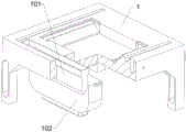
Fig. 1 is a schematic perspective view of the present invention.
Fig. 2 is a schematic view of a first partially cut-away structure of the present invention.
Fig. 3 is a schematic view of a partially cut-away structure of the drive mechanism of the present invention.
Fig. 4 is a schematic view of a positioning mechanism of the present invention in partial cross-section.
Fig. 5 is a schematic view of a second partially cut-away structure of the present invention.
FIG. 6 is a schematic view of a first partially cut-away configuration of the shielding mechanism of the present invention.
FIG. 7 is a schematic view of a second partially cut-away configuration of the shielding mechanism of the present invention.
Fig. 8 is a schematic view of a first partially cut-away configuration of the cleaning mechanism of the present invention.
Fig. 9 is a schematic view of a second partially cut-away configuration of the cleaning mechanism of the present invention.
Fig. 10 is a schematic view of a third partially cut-away configuration of the cleaning mechanism of the present invention.
Fig. 11 is a schematic view of a third partial cross-sectional structure of the present invention.
Fig. 12 is a schematic view of a partially cut-away structure of a storage mechanism of the present invention.
Fig. 13 is a schematic view of a partially cut-away structure of a cushioning mechanism of the present invention.
Wherein: 1-supporting seat, 2-n type frame, 21-non-slip block, 3-pressurizing plate, 4-locating frame, 5-lead screw, 6-driving mechanism, 61-servo motor, 62-driving shaft, 63-transmission component, 64-internal thread locating wheel, 7-locating mechanism, 71-placing plate, 72-hinged plate, 73-supporting spring, 74-pressure detector, 75-sliding shaft, 8-shielding mechanism, 81-shielding plate, 82-shielding side plate, 83-threaded pipe, 84-lifting frame, 85-sleeve, 86-telescopic rod, 87-limit spring, 9-cleaning mechanism, 91-magnetic frame, 92-first reel, 93-first pull wire, 94-second reel, 95-second pull wire, 96-reset spring, 97-sliding frame, 98-elastic brush, 99-pushing rod, 910-guiding frame, 10-storing mechanism, 101-guiding pipe, 102-storing box, 11-buffering mechanism, 111-buffering ring, 112-buffering spring.
Detailed Description
It should be noted that in the various embodiments described, identical components are provided with identical reference numerals or identical component names, wherein the disclosure contained throughout the description can be transferred in a meaning to identical components having identical reference numerals or identical component names. The position specification, upper, lower, lateral, etc. selected in the description are also referred to directly in the description and the figures shown and are transferred in the sense of a new position when the position is changed.
Example 1
The utility model provides a building cement piece resistance to compression detection device, including supporting seat 1, n type frame 2, non slipping spur 21, the pressurization board 3, locating rack 4, lead screw 5, actuating mechanism 6 and positioning mechanism 7, please see the illustration of fig. 1-4, install n type frame 2 between the outside left and right sides face middle part of supporting seat 1 through bolted connection's mode, n type frame 2 middle part slidingtype cross-under has locating rack 4, the rigid coupling of locating rack 4 bottom has pressurization board 3, when pressurization board 3 moves down and contacts with the cement piece, the rigid coupling has lead screw 5 in pressurization board 3 top and the locating rack 4 between the top, lead screw 5 runs through n type frame 2 middle part, the rigid coupling of supporting seat 1 bottom has four non slipping spur 21, be provided with actuating mechanism 6 on n type frame 2, when actuating mechanism 6 functions, be provided with positioning mechanism 7 on the supporting seat 1, when the cement piece is put on positioning mechanism 7, positioning mechanism 7 can realize carrying out the location to the cement piece.
The driving mechanism 6 comprises a servo motor 61, a driving shaft 62, a transmission assembly 63 and an internal thread positioning wheel 64, as shown in fig. 2 and 3, the internal thread positioning wheel 64 is rotatably connected in the middle of the top of the n-type frame 2, the internal thread positioning wheel 64 is in threaded connection with the screw rod 5, when the internal thread positioning wheel 64 rotates, the internal thread positioning wheel 64 can drive the screw rod 5 to move, the driving shaft 62 is rotatably connected on the right side of the top of the n-type frame 2, the transmission assembly 63 is connected between the upper part of the driving shaft 62 and the internal thread positioning wheel 64, the transmission assembly 63 consists of a belt pulley and a flat belt, the belt pulley is fixedly sleeved on the upper part of the driving shaft 62, the flat belt is wound between the internal thread positioning wheel 64 and the belt pulley, the servo motor 61 is fixedly connected on the right side of the outer top of the n-type frame 2, and the end part of an output shaft of the servo motor 61 is fixedly connected with the top of the driving shaft 62.
The positioning mechanism 7 comprises a placing plate 71, a hinge plate 72, a supporting spring 73, a pressure detector 74 and a sliding shaft 75, wherein the supporting spring 73 is connected in the middle of the outer top of the supporting seat 1, the tail end of the supporting spring 73 is fixedly connected with the placing plate 71, the placing plate 71 can position cement blocks, the placing plate 71 is positioned under the pressurizing plate 3, the pressure detector 74 is arranged in the middle of the inner bottom of the placing plate 71, the sliding shaft 75 is connected at the left top of the supporting seat 1 in a bilateral symmetry sliding manner, the hinge plates 72 are sleeved at the middle parts of the sliding shafts 75 at the left side and the right side in a rotating manner, and the inner ends of the hinge plates 72 at the left side and the right side are respectively connected with the left side and the right side of the placing plate 71 in a rotating manner.
Firstly placing a cement block in a placing plate 71 to be in contact with a pressure detector 74, positioning the cement block by the placing plate 71, enabling the cement block to accurately correspond to a pressurizing plate 3, simultaneously, driving the placing plate 71 to move downwards for a certain distance, compressing a supporting spring 73, driving a hinged plate 72 to swing downwards by the placing plate 71, restarting a servo motor 61 to drive a screw rod 5 to rotate reversely, driving a transmission assembly 63 to rotate reversely by the screw rod 5, driving an internal thread positioning wheel 64 to rotate reversely by the transmission assembly 63, driving the screw rod 5 to move downwards by the internal thread positioning wheel 64, driving the pressurizing plate 3 to move downwards by the downward movement of the screw rod 5, detecting the pressure resistance of the cement block by the pressurizing plate 3 when the pressurizing plate 3 moves downwards to be in contact with the cement block, detecting the pressure value by the pressure detector 74, the pressure data is transmitted to the computer end for recording, the device can be used more firmly due to the effect of the anti-skid blocks 21, when the cement blocks are broken, the recording equipment records the detected pressure-resistant data, at the moment, the servo motor 61 is started to drive the screw rod 5 to rotate positively, the internal thread positioning wheel 64 drives the screw rod 5 to move forward to reset, the screw rod 5 resets to drive the pressurizing plate 3 to move upward to reset to be separated from the cement blocks, the servo motor 61 is closed, the broken cement blocks are taken down from the placing plate 71, and the placing plate 71 moves upward to reset to drive the hinge plates 72 to swing upward to reset due to the effect of the supporting springs 73.
Example 2
On the basis of embodiment 1, the device further comprises a shielding mechanism 8, the shielding mechanism 8 comprises a shielding plate 81, shielding side plates 82, threaded pipes 83, lifting frames 84, sleeves 85, telescopic rods 86 and limiting springs 87, as shown in fig. 5-7, the shielding side plates 82 are mounted between the left and right sides of the top of the supporting seat 1 and the lower parts of the left and right side surfaces of the n-type frames 2 respectively in a bolt connection mode, the shielding side plates 82 can shield the projected scraps, the shielding plates 81 are rotatably connected between the front sides and the rear sides of the left and right side shielding side plates 82, the shielding plates 81 can shield the projected scraps, the inner right side surfaces of the front and rear side shielding plates 81 are rotatably connected with the sleeves 85, the inner sides of the two sleeves 85 are slidably connected with the telescopic rods 86, the inner sides of the two telescopic rods 86 are respectively connected with the limiting springs 87, the threaded pipes 83 are fixedly sleeved on the driving shafts 62, the outer sides of the threaded pipes 83 are threadedly connected with lifting frames 84, the two sides of the n-type frames 2 are slidably penetrated through the lifting frames 84, and the front and rear ends and the inner ends of the lifting frames 86 are rotatably connected with the telescopic rods 84 respectively, and the telescopic rods 84 can be rotatably moved when the lifting frames 84 are rotatably connected.
The cleaning mechanism 9 comprises a magnetic frame 91, a first reel 92, a first pull wire 93, a second reel 94, a second pull wire 95, a return spring 96, a sliding frame 97, an elastic brush 98, a pushing rod 99 and a guide frame 910, wherein the guide frame 910 is fixedly connected on the outer top of the supporting seat 1 in a bilateral symmetry manner, the sliding frame 97 is connected between the left and right guide frames 910 in a sliding manner, the return spring 96 is connected between the left and right sides of the lower part of the front side surface of the sliding frame 97 and the inner front side surface of the left and right guide frames 910 respectively, the elastic brush 98 is connected with the outer top of the supporting seat 1 in a sliding manner in a penetrating manner, when the elastic brush 98 moves, the elastic brush 98 can clean small cement blocks, the pushing rod 99 is arranged on the inner top of the sliding frame 97 in a welding connection manner, when the pushing rod 99 moves forwards, the pushing rod 99 can push broken cement blocks, the front side of the upper part of the outer right side surface of the supporting seat 1 is rotatably connected with the second reel 94, the second reel 94 is provided with the second stay wire 95, the tail end of the second stay wire 95 penetrates through the supporting seat 1 and is fixedly connected with the lower part of the front side surface of the sliding frame 97, the upper part of the outer right side of the n-type frame 2 is rotatably connected with the first reel 92, the right side of the first reel 92 and the right side of the second reel 94 are transmitted through the synchronous belt assembly, the first reel 92 is wound with the first stay wire 93, the right side of the n-type frame 2 is slidably connected with the magnetic frame 91, the magnetic frame 91 is fixedly connected with the tail end of the first stay wire 93, and when the magnetic frame 91 moves downwards, the magnetic frame 91 can drive the first stay wire 93 to move downwards, and the lifting frame 84 moves upwards to be in contact with the magnetic frame 91.
When the servo motor 61 is started to drive the driving shaft 62 to rotate reversely, the pressurizing plate 3 moves downwards to detect the compression resistance of the cement block, meanwhile, the driving shaft 62 rotates reversely to drive the threaded pipe 83 to rotate reversely, the threaded pipe 83 rotates reversely to drive the lifting frame 84 to move upwards, the lifting frame 84 moves upwards to drive the telescopic rod 86 to move upwards, the telescopic rod 86 moves upwards to drive the sleeve 85 to move upwards through the limiting spring 87, the sleeve 85 moves upwards to drive the shielding plate 81 to swing upwards, when the shielding plate 81 swings upwards to be in a vertical state, the sleeve 85 stops moving upwards, the telescopic rod 86 continues to move upwards to enable the limiting spring 87 to be stretched, and then when the cement block is detected by the compression resistance, the shielding plate 81 and the shielding side plate 82 block the sprayed fragments. After the cement blocks are broken, the servo motor 61 is started to drive the driving shaft 62 to rotate positively, the driving shaft 62 drives the threaded pipe 83 to rotate positively, the threaded pipe 83 rotates positively to drive the lifting frame 84 to move downwards for resetting, the lifting frame 84 resets to drive the telescopic rod 86 to move downwards for resetting, the limit spring 87 also contracts for resetting, and the shielding plate 81 swings downwards for resetting. Therefore, the damage to surrounding personnel caused by the fragments sprayed when the cement blocks are detected by compression resistance can be prevented, and the safety of the surrounding personnel is ensured.
Firstly, a collecting container is placed below the front side of a supporting seat 1, when a pressurizing plate 3 moves downwards to detect the compression resistance of a cement block, a lifting frame 84 moves upwards to be in contact with a magnetic frame 91, the magnetic frame 91 is magnetically adsorbed on the lifting frame 84, when the lifting frame 84 moves downwards, the lifting frame 84 moves downwards to drive the magnetic frame 91 to move downwards, the magnetic frame 91 moves downwards to drive a first pull wire 93 to move downwards, the first pull wire 93 moves downwards to drive a first reel 92 to rotate reversely, the first reel 92 rotates reversely to drive a second reel 94 to rotate reversely through a synchronous belt assembly, the second reel 94 rotates reversely to wind a second pull wire 95, the second pull wire 95 winds to drive a sliding frame 97 to move forwards, a return spring 96 is compressed, the sliding frame 97 moves forwards to drive a push rod 99 and an elastic brush 98 to move forwards, the push rod 99 moves forwards to drive a large cement block to move forwards to be separated from contact with the placing plate 71, the large cement blocks continue to move forward and drop into the collecting container out of contact with the supporting seat 1, the elastic hairbrush 98 moves forward to drive the small cement blocks to move forward and separate from the placing plate 71 and the supporting seat 1, the small cement blocks drop into the collecting container, when the magnetic frame 91 moves down to the maximum stroke, the magnetic frame 91 stops moving down, the lifting frame 84 continues to move down and separate from the magnetic frame 91, the sliding frame 97 moves backward to reset to drive the elastic hairbrush 98 and the pushing rod 99 to move backward to reset due to the effect of the reset spring 96, the sliding frame 97 moves backward to drive the second stay 95 to move backward, the second stay 95 moves backward to drive the second reel 94 to reset in a forward rotation, so that the first reel 92 resets the first stay 93 in a winding way, the first stay 93 resets to drive the magnetic frame 91 to move upward to reset, the broken cement blocks are removed and treated without people, so that the treatment efficiency of the broken cement blocks is improved.
Example 3
On the basis of embodiment 1 and embodiment 2, still include storage mechanism 10, storage mechanism 10 is including passage 101 and storage case 102, please see fig. 11 and 12, the fixed cross-under in the middle of supporting seat 1 front portion has passage 101, storage case 102 is installed through bolted connection's mode to the top front side in supporting seat 1, storage case 102 and passage 101 bottom fixed connection and intercommunication, and storage case 102 can realize collecting broken cement piece, and the discharge gate of storage case 102 is provided with the chamber door.
The device further comprises a buffer mechanism 11, wherein the buffer mechanism 11 comprises a buffer ring 111 and buffer springs 112, as shown in fig. 11 and 13, the outer side of the pressurizing plate 3 is connected with the buffer ring 111 in a sliding manner along the circumferential direction, and four buffer springs 112 are connected between the upper part of the buffer ring 111 and the outer side of the pressurizing plate 3.
When the broken cement pieces are pushed down from the placement plate 71 by the pushing rod 99 and the elastic brush 98, the broken cement pieces fall into the guide pipe 101, and the broken cement pieces in the guide pipe 101 fall into the storage bin 102. When the bin 102 contains an amount of broken cement pieces, the collection container is placed under the bin 102, the bin door of the bin 102 is opened, and the broken cement pieces in the bin 102 fall into the collection container. Thus, the broken cement blocks are more convenient to collect and treat.
When the pressurizing plate 3 moves downwards, the pressurizing plate 3 drives the buffer ring 111 to move downwards through the buffer spring 112, the buffer ring 111 moves downwards to be in contact with the cement block, the buffer ring 111 buffers the pressurizing plate 3 through the buffer spring 112, and the buffered pressurizing plate 3 moves downwards to be in contact with the cement block for compression detection. When the pressurizing plate 3 moves upwards for resetting, the pressurizing plate 3 drives the buffer ring 111 to move upwards for resetting through the buffer spring 112. In this way, the pressing plate 3 is prevented from being damaged by violent contact with the cement block, thereby ensuring the service life of the pressing plate 3.
Finally, it is necessary to state that: the foregoing is provided to assist in understanding the technical solutions of the present invention, and is not to be construed as limiting the scope of protection of the present invention; insubstantial modifications and variations from the above teachings are within the scope of the invention as claimed.
Claims (8)
1. The utility model provides a building cement piece resistance to compression detection device, including supporting seat (1), n type frame (2), pressurization board (3), locating rack (4) and lead screw (5), the rigid coupling has n type frame (2) between the left and right sides face middle part outside supporting seat (1), the cross-under of n type frame (2) middle part slidingtype has locating rack (4), locating rack (4) bottom rigid coupling has pressurization board (3) that are used for carrying out the resistance to compression detection to the cement piece, rigid coupling has lead screw (5) in pressurization board (3) top and locating rack (4) between the top, lead screw (5) run through n type frame (2) middle part, characterized by is provided with actuating mechanism (6) that are used for driving lead screw (5) removal on n type frame (2), be provided with on supporting seat (1) and be used for carrying out positioning mechanism (7) to the cement piece.
2. The device for detecting the compression resistance of the building cement block according to claim 1 is characterized by further comprising an anti-slip block (21), wherein four anti-slip blocks (21) are fixedly connected to the bottom of the supporting seat (1).
3. The device for detecting the compression resistance of the building cement block according to claim 1, wherein the driving mechanism (6) comprises a servo motor (61), a driving shaft (62), a transmission assembly (63) and an internal thread locating wheel (64), the internal thread locating wheel (64) used for driving the screw rod (5) to move is rotationally connected in the middle of the top of the n-type frame (2), the internal thread locating wheel (64) is in threaded connection with the screw rod (5), the driving shaft (62) is rotationally connected on the right side of the top of the n-type frame (2), the transmission assembly (63) is connected between the upper part of the driving shaft (62) and the internal thread locating wheel (64), the transmission assembly (63) consists of a belt pulley and a flat belt, the belt pulley is fixedly sleeved on the upper part of the driving shaft (62), the flat belt is wound between the internal thread locating wheel (64) and the belt pulley, the servo motor (61) is fixedly connected on the right side of the outer top of the n-type frame (2), and the end part of the output shaft of the servo motor (61) is fixedly connected with the top of the driving shaft (62).
4. The building cement block compression-resistant detection device according to claim 3 is characterized in that the positioning mechanism (7) comprises a placement plate (71), hinge plates (72), a supporting spring (73), a pressure detector (74) and a sliding shaft (75), the middle of the outer top of the supporting seat (1) is connected with the supporting spring (73), the tail end of the supporting spring (73) is fixedly connected with the placement plate (71) for positioning a cement block, the placement plate (71) is positioned under the compression plate (3), the pressure detector (74) is arranged in the middle of the inner bottom of the placement plate (71), the sliding shafts (75) are symmetrically connected at the outer top of the supporting seat (1) in a sliding mode, the middle parts of the hinge plates (72) at the left side and the right side are rotatably sleeved, and the inner ends of the hinge plates (72) at the left side and the right side are rotatably connected with the left side and the right side surfaces of the placement plate (71).
5. The device for detecting the compression resistance of the building cement block according to claim 4, further comprising a shielding mechanism (8) for shielding the burst chips, wherein the shielding mechanism (8) comprises a shielding plate (81), a shielding side plate (82), a threaded pipe (83), a lifting frame (84), a sleeve (85), a telescopic rod (86) and a limiting spring (87), the shielding side plate (82) for shielding the burst chips is fixedly connected between the left and right sides of the top of the supporting seat (1) and the lower parts of the left and right side surfaces outside the n-type frame (2), the shielding plates (81) used for shielding the burst chips are rotatably connected between the front sides and the rear sides of the shielding plates (82), the inner right sides of the shielding plates (81) at the front side and the rear side are rotatably connected with sleeves (85), the inner sides of the two sleeves (85) are slidably connected with telescopic rods (86), limiting springs (87) are respectively connected between the inner sides of the two telescopic rods (86) and the outer sides of the two sleeves (85), threaded pipes (83) are fixedly sleeved on a driving shaft (62), lifting frames (84) used for driving the telescopic rods (86) to move are in threaded connection with the outer sides of the threaded pipes (83), the lifting frames (84) slidably penetrate through n-type frames (2), the front and back sides of the lifting frame (84) are respectively connected with the inner ends of the telescopic rods (86) at the front and back sides in a rotating way.
6. The device for detecting the compression resistance of the building cement block according to claim 5, further comprising a cleaning mechanism (9) for pushing out the broken cement block, wherein the cleaning mechanism (9) comprises a magnetic frame (91), a first reel (92), a first stay wire (93), a second reel (94), a second stay wire (95), a return spring (96), a sliding frame (97), an elastic brush (98), a pushing rod (99) and a guide frame (910), the guide frame (910) is fixedly connected on the left top and the right top of the supporting seat (1) in a bilateral symmetry manner, a sliding frame (97) is connected between the guide frames (910) on the left side and the right side in a sliding manner, a return spring (96) is connected between the left side and the right side of the lower part of the front side of the sliding frame (97) and the inner front side of the guide frame (910) on the left side respectively, the sliding through connection on the sliding frame (97) is provided with the elastic brush (98) for cleaning the cement block on the small block, the elastic brush (98) is contacted with the outer top of the supporting seat (1), the sliding frame (97) is fixedly connected on the inner top of the sliding frame (97) with the outer side of the supporting seat (99) for pushing the broken cement block on the second reel (94), the second draws wire (95) tail end slidingtype run through supporting seat (1) and carriage (97) leading flank lower part fixed connection, n type frame (2) outer right side upper portion pivoted is connected with first reel (92), pass through synchronous belt assembly transmission between first reel (92) right side and second reel (94) right side, it has first acting as go-between (93) to wind on first reel (92), n type frame (2) right side sliding is connected with magnetic frame (91) that are used for driving first acting as go-between (93) downwardly moving, magnetic frame (91) and first acting as go-between (93) tail end fixed connection, crane (84) upward movement and magnetic frame (91) contact.
7. The device for detecting the compression resistance of the building cement blocks according to claim 6, further comprising a storage mechanism (10) for collecting the pushed broken cement blocks, wherein the storage mechanism (10) comprises a material guiding pipe (101) and a material storage box (102), the material guiding pipe (101) is fixedly connected in the middle of the front part of the supporting seat (1), the material storage box (102) for collecting the broken cement blocks is fixedly connected to the front side of the inner top of the supporting seat (1), the material storage box (102) is fixedly connected and communicated with the bottom end of the material guiding pipe (101), and a box door is arranged at a discharge hole of the material storage box (102).
8. The device for detecting the compression resistance of the building cement block according to claim 7, further comprising a buffer mechanism (11) for buffering the pressurizing plate (3), wherein the buffer mechanism (11) comprises a buffer ring (111) and buffer springs (112), the buffer ring (111) is connected to the outer side of the pressurizing plate (3) in a sliding mode along the circumferential direction, and four buffer springs (112) are connected between the upper portion of the buffer ring (111) and the outer side of the pressurizing plate (3).
Priority Applications (1)
| Application Number | Priority Date | Filing Date | Title |
|---|---|---|---|
| CN202310165373.3A CN116026692A (en) | 2023-02-25 | 2023-02-25 | Building cement piece resistance to compression detection device |
Applications Claiming Priority (1)
| Application Number | Priority Date | Filing Date | Title |
|---|---|---|---|
| CN202310165373.3A CN116026692A (en) | 2023-02-25 | 2023-02-25 | Building cement piece resistance to compression detection device |
Publications (1)
| Publication Number | Publication Date |
|---|---|
| CN116026692A true CN116026692A (en) | 2023-04-28 |
Family
ID=86072499
Family Applications (1)
| Application Number | Title | Priority Date | Filing Date |
|---|---|---|---|
| CN202310165373.3A Withdrawn CN116026692A (en) | 2023-02-25 | 2023-02-25 | Building cement piece resistance to compression detection device |
Country Status (1)
| Country | Link |
|---|---|
| CN (1) | CN116026692A (en) |
Cited By (4)
| Publication number | Priority date | Publication date | Assignee | Title |
|---|---|---|---|---|
| CN116499880A (en) * | 2023-06-27 | 2023-07-28 | 天津津贝尔建筑工程试验检测技术有限公司 | Building material performance detection equipment |
| CN117091952A (en) * | 2023-10-18 | 2023-11-21 | 赣州市榕盛新型建材有限公司 | Cement prefab compressive capacity detection device |
| CN117571487A (en) * | 2023-11-23 | 2024-02-20 | 青岛凯瑞电子有限公司 | Electronic components metal casing resistance to compression detection device |
| CN117571487B (en) * | 2023-11-23 | 2024-05-14 | 青岛凯瑞电子有限公司 | Electronic components metal casing resistance to compression detection device |
-
2023
- 2023-02-25 CN CN202310165373.3A patent/CN116026692A/en not_active Withdrawn
Cited By (6)
| Publication number | Priority date | Publication date | Assignee | Title |
|---|---|---|---|---|
| CN116499880A (en) * | 2023-06-27 | 2023-07-28 | 天津津贝尔建筑工程试验检测技术有限公司 | Building material performance detection equipment |
| CN116499880B (en) * | 2023-06-27 | 2023-09-05 | 天津津贝尔建筑工程试验检测技术有限公司 | Building material performance detection equipment |
| CN117091952A (en) * | 2023-10-18 | 2023-11-21 | 赣州市榕盛新型建材有限公司 | Cement prefab compressive capacity detection device |
| CN117091952B (en) * | 2023-10-18 | 2024-04-12 | 赣州市榕盛新型建材有限公司 | Cement prefab compressive capacity detection device |
| CN117571487A (en) * | 2023-11-23 | 2024-02-20 | 青岛凯瑞电子有限公司 | Electronic components metal casing resistance to compression detection device |
| CN117571487B (en) * | 2023-11-23 | 2024-05-14 | 青岛凯瑞电子有限公司 | Electronic components metal casing resistance to compression detection device |
Similar Documents
| Publication | Publication Date | Title |
|---|---|---|
| CN116026692A (en) | Building cement piece resistance to compression detection device | |
| CN108303335B (en) | Rubber material abrasion resistance testing device | |
| CN110922041A (en) | Self-suction float glass cutting device | |
| CN113670736A (en) | Circuit board compressive property detection device for intelligent manufacturing | |
| CN219065526U (en) | Detection device | |
| CN112584619A (en) | Be used for PCB circuit board corner cutting equipment | |
| CN218903009U (en) | Positioning device capable of conveniently and rapidly removing ash for capacitive touch screen processing | |
| CN216625845U (en) | Power supply unit video monitoring device | |
| CN215154820U (en) | Conveyor of black glue AOI detection machine | |
| CN115070568A (en) | Quick grinding device of metal | |
| CN214309478U (en) | Device for testing tightness of belt | |
| CN210444151U (en) | Rotor dynamic balance mechanism | |
| CN111665134A (en) | A electron special material capability test mechanism for electronic product production | |
| CN219810774U (en) | Laminating quality detection device | |
| CN114162408B (en) | Sorting device for testing shielding part | |
| CN217443031U (en) | Detection apparatus capable of detecting preliminary strength of elevator processing section bar | |
| CN220751839U (en) | Hydraulic support stand column test bed | |
| CN220781359U (en) | End cover assembly detection device | |
| CN220040075U (en) | Motor product surface compressive strength detection equipment | |
| CN214235109U (en) | Be used for food production digital intelligent metal foreign matter detector | |
| CN219956972U (en) | Soil heavy metal sampling detects integrative device | |
| CN215625288U (en) | Vacuum adsorption device for laminated glass | |
| CN214168529U (en) | Needle detector | |
| CN215573673U (en) | Impact collision test device applied to steel structure | |
| CN117464601A (en) | Chip detection machine with screening structure |
Legal Events
| Date | Code | Title | Description |
|---|---|---|---|
| PB01 | Publication | ||
| PB01 | Publication | ||
| WW01 | Invention patent application withdrawn after publication | ||
| WW01 | Invention patent application withdrawn after publication |
Application publication date: 20230428 |