Disclosure of Invention
The invention mainly solves the problem of poor power supply reliability of the distribution network in the prior art; a distribution network voltage active regulation and control method based on a multi-source dynamic data aggregation technology is provided.
The technical problem of the invention is mainly solved by the following technical scheme: a distribution network voltage active regulation and control method based on a multi-source dynamic data aggregation technology comprises the following steps:
s1: setting a plurality of regulating and controlling devices for voltage monitoring, and if the monitoring voltage is lower than the threshold range, entering the step S2;
s2: performing voltage rechecking and judging whether to perform primary voltage regulation or perform key monitoring according to a rechecking result;
s3: if the voltage can not be boosted after the first voltage regulation, performing second voltage regulation in a capacitor voltage regulation mode;
s4: and if the voltage after the second voltage regulation is still lower than the threshold range, performing third voltage regulation through line switching.
Preferably, the specific method for monitoring the voltage comprises the following steps: the main power supply line side regulation and control device samples and monitors that three-phase voltage fluctuates between 190V and 198V, the time lasts for 5 minutes or more, and a microprocessor of the main power supply line side regulation and control device generates early warning information of low voltage and enters a voltage rechecking link.
Preferably, the specific method for voltage rechecking is as follows: transfer main power supply residual current operated circuit breaker, intelligent circuit breaker and load voltage sampling point U A 、U B 、U C Three-phase voltage data, the data is respectively added according to the A phase voltage, the B phase voltage and the C phase voltage and divided by 3 to obtain the average value of the A phase voltage, the B phase voltage and the C phase voltage and a sampling point U A 、U B 、U C And comparing the voltage data, and determining that the voltage of the phase A, the voltage of the phase B and the voltage of the phase C are between 190V and 198V and the error is within +/-1%.
Preferably, the specific method for first voltage regulation is as follows: the main power supply public transformer substation regulating and controlling device reads tap joint gear information stored by the on-load tap changing controller, judges whether the on-load tap changing transformer meets the tap joint up-regulating condition, if yes, the main power supply public transformer substation regulating and controlling device sends a tap joint voltage regulating instruction to the on-load tap changing controller, the on-load tap changing controller controls the on-load tap changing transformer to complete tap joint voltage regulation, and whether tap joint regulation is successful or not is fed back to the on-load tap changing controller through the on-load tap changing controllerThe main power supply public transformer substation regulating and controlling device enters a voltage rechecking link to regulate the voltage and then is subjected to U A 、U B 、U C Checking the three-phase voltage data, judging whether the voltage is qualified, and finishing the voltage regulation; if the voltage does not meet the preset value, the main power supply public transformer substation regulating and controlling device sends an on-load tap changer tap joint up-regulating instruction; otherwise, the main power supply public transformer substation regulating and controlling device sends the information that the lifting voltage cannot be regulated through the tap to the main power supply line side regulating and controlling device, and the main power supply line side regulating and controlling device regulates and controls the voltage for the second time.
Preferably, the second voltage regulation specifically comprises: calling intelligent capacitor switching signals by a main power supply line side regulation and control device, and after determining that a capacitor bank can be switched to regulate voltage, according to U A 、U B 、U C The three-phase voltage data enters the step of partial compensation, partial compensation and total compensation to gradually input the capacitor, and after each step is finished, the load voltage sampling U is summoned and measured A 、U B 、U C Whether the three-phase voltage data are in accordance with the range of 198V-208V or not, and stopping the input of the capacitor bank if the three-phase voltage data are in accordance with the range; if the voltage regulation condition cannot be met, the capacitor bank is continuously put into operation, and after all the capacitors are put into operation, the voltage meets the standard, and the voltage regulation is finished; otherwise, if the voltage is still lower than 187V, the third voltage regulation is performed.
Preferably, the third voltage regulation specifically comprises: the main power supply line side regulating device is used for regulating U A 、U B 、U C Three-phase voltage data is pushed to a standby power supply public transformer substation regulating and controlling device through an LORA communication channel, the standby power supply public transformer substation regulating and controlling device evaluates whether public transformer load meets the condition of switching, the condition meets, a microprocessor of the standby power supply public transformer substation regulating and controlling device sends a switching-on instruction of a standby power supply corresponding to a standby power supply residual current operated protector, and then a standby supply voltage sampling U of a main power supply line side regulating and controlling device is called for A 、U B 、U C And the three-phase voltage data successfully responds to prove that the power supply and the power transmission of the standby power supply are successful, the standby circuit power transmission link is entered, otherwise, the standby circuit power transmission link is retried once and is not successful, the main power supply circuit side regulating and controlling device pushes the standby power supply failure starting alarm information, and the circuit switching is finished.
AsPreferably, the specific method of the power transmission link of the backup line includes: the microprocessor of the main power supply line side regulation and control device firstly sends a command of disconnecting the main power supply residual current operated circuit breaker, and after a plurality of seconds, calls and tests the intelligent circuit breaker and the load voltage sampling U corresponding to the main power supply line side regulation and control device A 、U B 、U C Three phase voltage data, determining U A 、U B 、U C The voltage is 0V; then a microprocessor of the main power supply line side regulation and control device sends a switching-on instruction of the standby power supply residual current operated circuit breaker, and after a plurality of seconds of rest, the intelligent circuit breaker and the load voltage sampling U corresponding to the main power supply line side regulation and control device are called up and tested again A 、U B 、U C Three-phase voltage data, and all voltages are greater than 198V and above; waiting for a plurality of seconds again, rechecking the intelligent circuit breaker and the load voltage sampling U again A 、U B 、U C Three-phase voltage data, and the voltage data should be more than 198V and above; and (4) pushing the success information of the switching by a microprocessor of the main power supply line side regulation and control device, and finishing the line switching.
Preferably, after the voltage rechecking, the method further comprises a superior voltage rechecking, and the specific method comprises the following steps: u pushed by main power supply line side regulation and control device received by main power supply public transformer substation regulation and control device A 、U B 、U C Three-phase voltage data and load voltage sampling U in the memory A 、U B 、U C Three-phase voltage data are extracted by shifting forward 5, 15, 30, 45, 60, 75, 90, 105 and 120 minutes according to the time of receiving the data A 、U B 、U C And comparing and judging the three-phase voltage data to judge whether the three-phase voltage data fluctuate within the range of 198V-208V or not, determining whether a public transformer substation provided with an on-load tap changing transformer is installed or not, and moving 5 groups of U (U) groups of 5 minutes, 15 minutes, 30 minutes, 45 minutes and 60 minutes forwards when the main power supply public transformer substation regulating and controlling device recalls received data AB 、U BC 、U AC Three-phase line voltage data, and calculating according to the phase voltage = line voltage ÷ 3 to obtain U A 、U B 、U C Three-phase voltage data and reported U A 、U B 、U C Comparing the three-phase voltage data, and judging whether the voltage is in the range of 198V-208V againInternal fluctuations.
The beneficial effects of the invention are: three-level voltage regulation is performed through an automatic voltage regulation method, so that the power supply quality of the distribution network is ensured, and the power supply reliability of the distribution network is improved.
Detailed Description
In order to make the objects, technical solutions and advantages of the present invention more apparent, the technical solutions in the embodiments of the present invention are further described in detail by the following embodiments in conjunction with the accompanying drawings. It should be understood that the specific embodiments described herein are merely illustrative of the invention and do not limit the invention.
Example (b): a distribution network voltage active regulation and control method based on multisource dynamic data aggregation technology is disclosed, the power supply quality processing method of the invention depends on a power supply quality regulation and control device, comprises regulation and control devices which are distributed on a distribution network line, performs line switching according to a control instruction transmitted by the regulation and control devices, an intelligent double-path alternating current contactor connected with the regulation and control devices, an intelligent capacitor used for boosting power supply in the process of voltage regulation and connected with the regulation and control devices, and a control device used for controlling the power supply quality; the residual current operated circuit breaker comprises a main residual current operated circuit breaker and a standby residual current operated circuit breaker, is used for regulating and controlling the on-off of the line, and is connected with a regulating and controlling device and an intelligent double-path alternating current contactor; the low-voltage bus is used for low-voltage electric transportation and is connected with the main residual current operated circuit breaker, the standby residual current operated circuit breaker and the intelligent capacitor, the low-voltage bus provides an A-path power supply for the intelligent double-path alternating current contactor through the main residual current operated circuit breaker, and the low-voltage bus provides a B-path power supply for the intelligent double-path alternating current contactor through the standby residual current operated circuit breaker; the on-load tap changer is used for adjusting the voltage of the 10KV line and outputting the adjusted voltage to the low-voltage busbar; the on-load voltage regulation controller receives the control instruction of the regulating and controlling device to control the on-load voltage regulation transformer to regulate voltage; and the wind-solar complementary system supplies power to the regulation and control device and the on-load voltage regulation controller.
The regulation and control device is composed of a microprocessor 1, a power supply 2, a charging circuit 3, a lithium battery 17, a voltage reduction circuit 4, an LCD (liquid crystal display) 5, a keyboard input 6, a 5G communication module 7, a LORA (low order radio Access) communication module 8, an RS485 interface row 9, a main supply voltage sampling 10, a load voltage sampling 11, a standby supply voltage sampling 12, a current sampling 13, a main supply power coil relay 14, 3 groups of standby supply power coil relays 15, an AD (analog-to-digital) conversion circuit, an intelligent capacitor, an on-load voltage regulation controller and 2 groups of RS485 special interfaces 16; the power supply is connected with the charging circuit, the charging circuit is connected with the lithium battery, the charging circuit and the lithium battery are connected with the voltage reduction circuit, and the voltage reduction circuit is connected with the microprocessor and provides a circuit board working power supply; the microprocessor is connected with the LCD, the keyboard input is connected with the microprocessor, and the setting or modification of the parameters and the threshold value of the regulating device and the like are realized; the 5G communication module, the LORA communication module and the RS485 interface row are connected with the microprocessor, and communication connection between a remote control and a regulation device is established; the main supply voltage sampling, the load voltage sampling, the standby supply voltage sampling and the current sampling are connected with a microprocessor through an AD conversion circuit, and a complete monitoring data acquisition channel is established; the main power supply coil relay and the 3 groups of standby power supply coil relays are respectively connected with the microprocessor, the normally open main contacts of the main power supply coil relay and the 3 groups of standby power supply coil relays are connected with a power supply, and 1 group of alternating current contactors are reserved to control a main power supply and 3 groups of standby power supply switching control circuits; the main power supply public transformer is provided with an on-load voltage regulating transformer, the regulating and controlling device is connected with an on-load voltage regulating controller through a special RS485 interface, and the on-load voltage regulating controller is connected with the on-load voltage regulating transformer; the main power supply public transformer substation is provided with an intelligent capacitor, and the regulation and control device is directly connected with the intelligent capacitor by adopting a special RS485 interface.
The main power supply public transformer substation regulating and controlling device mainly adopts commercial power to charge the lithium battery of the regulating and controlling device and directly supply the lithium battery to a circuit board. When the mains supply is normal, the charging circuit converts alternating current into direct current of 7.4V after rectification, and when the storage capacity of the lithium battery is insufficient, the charging is carried out; the other path reduces the voltage of 7.4V to 3.3V through a voltage reduction circuit to be supplied to the circuit board of the regulating and controlling device. When the mains supply is powered off or the public power distribution equipment fails and has power failure, the voltage reduction circuit of the regulation and control device detects that the voltage of the mains supply is 0V, the voltage of the lithium battery is reduced to 3.3V and then the voltage is supplied to a circuit board of the regulation and control device, and the regulation and control device can realize uninterrupted power supply within 24 hours.
A5G and LORA double communication module is adopted, LORA communication is preferred during data communication, and the smoothness of a data communication channel is guaranteed by a design method of 5G communication module standby. According to the voltage quality control region division, 1 transformer substation is deployed in a main power supply public transformer substation, 3 transformer substations which take 13-base main rods as examples are deployed in circuits and 1 transformer substation is deployed in a public transformer substation connected with a standby power supply, 5 control devices are deployed in the region, and data exchange, proofreading and control signal exchange are formed. And when the LORA communication is idle, signal response and proofreading data packets and the furthest deployed regulation and control device are adopted to carry out smooth proofreading on a communication channel according to 60-second intervals.
The regulation and control device is designed with two control modes of RS485 and coil relay, the RS485 is connected with the residual current operated circuit breaker or the intelligent circuit breaker, and the microprocessor of the regulation and control device sends the opening (closing) action of the residual current operated circuit breaker or the intelligent circuit breaker to control the switching of main power supply or standby power supply; the latter utilizes the main coil relay that supplies or supplies coil relay contact output 220V to connect with AC contactor coil, utilize the regulation and control device power to supply coil relay and supply coil relay two pairs of normally open contacts to connect with main, draw-off end and use the casing wiring row of regulation and control device to link to each other with AC contactor coil, after the regulation and control device circular telegram, microprocessor sends main coil relay coil circular telegram order of supplying at first, the electric actuation of relay is got the electricity, the normally open contact of relay becomes the normal close, the relay lead-out wire power is switched on, the electric actuation of AC contactor coil is got the electricity, main power supply circular telegram. When the regulating and controlling device is put into operation, the microprocessor does not send a coil conducting instruction and is in a state of waiting to be closed.
The data source of the regulation and control device is that data and signals such as three-phase voltage, current, residual current and switching value of the main power supply residual current operated circuit breaker are acquired by RS485, and data and signals such as three-phase voltage, current, power factor, switching state, input capacity and the like are pushed by the intelligent capacitor through RS 485; and secondly, a three-phase voltage is obtained by an external three-phase power supply of the regulating device through an AD conversion circuit, and a three-phase current obtained by the current transformer connected to the lower end of the outgoing line through AD conversion is connected to the three-phase voltage data obtained by the outgoing line end of the intelligent circuit breaker. And thirdly, the intelligent circuit breaker connected to the upper end of the outgoing line transmits three-phase voltage, current and switching value data and signals through RS 485. And fourthly, data and signals such as three-phase voltage, current, residual current, switching value and the like of the standby power supply residual current operated circuit breaker are acquired by utilizing RS485, and the function is only limited to on-pole regulation and control setting installed on a circuit pole or a public transformer substation provided with two-way power supply. And fifthly, reporting voltage data of the three-phase line through the on-load voltage regulation controller. The data acquisition mode of the public transformer substation without the double-circuit power supply condition is used for remotely calling and measuring the data of the regulating and controlling device in the power supply public transformer substation.
The power supply quality regulation and control device is respectively deployed by two different configurations of a public transformer substation and a line pole upper type, a main power supply and a standby power supply are erected by adopting the same pole line, a standby power supply line is arranged above the main power supply, a main power supply line is arranged below the main power supply, and the line pole upper type regulation and control device is deployed at the tail end of a branch line or a line, so that the purpose of regulating and controlling the voltage quality by switching a user is facilitated.
Deploying a public transformer substation regulation and control device: the public transformer substation can be deployed by adopting an on-load tap changer, a photovoltaic power supply and a double-circuit power supply. The main power supply source is connected with the upper end of a residual current operated circuit breaker of the main power supply source through a current transformer from the on-load voltage regulating transformer, and the lower end of the residual current operated circuit breaker is connected with a current transformer for monitoring load current through an intelligent circuit breaker; the public transformer substation is provided with photovoltaic, and the working power supply of the power supply quality regulation and control device is directly supplied with power by a lithium battery, so that the problems that communication is interrupted and a standby power supply cannot be started for power supply and the like caused by power failure of a main power supply line or a public transformer substation power supply device are solved.
The method comprises the following steps of deploying a line pole upper type regulation and control device: the working power supply of the regulating device is supplied with power by photovoltaic, and the regulating device is connected with each distribution device in a RS485 communication mode. The regulating and controlling device is responsible for controlling the on/off control and the operation data collection of the main power supply residual current operated circuit breaker or protector and the standby power supply residual current operated circuit breaker or protector; controlling the collection of switching, fault information and operation data, wherein the switching, the fault information and the operation data are formed by supplementing 20kvar intelligent capacitor groups by 3 components and supplementing 40kvar intelligent capacitor groups by 1 group; controlling the intelligent circuit breaker to be controlled in a closing (opening) mode and collecting operation data; the incoming line of the main power supply is connected with the upper end of the main power supply residual current operated circuit breaker or the protector through the current transformer, and the lower end lead is connected with the upper end of the intelligent circuit breaker; the standby power supply inlet wire is connected to the upper end of a standby power supply residual current operated circuit breaker or a protector through a current transformer, and the lower end lead is connected with the upper end of an intelligent circuit breaker; the lower end of the intelligent circuit breaker is connected with a user through a current transformer; the intelligent capacitor is connected to the upper end of the main power supply residual current operated circuit breaker or the protector in parallel.
The deployment principle of the line pole upper type regulating and controlling device is as follows: outside the intelligent capacitor group is deployed in the main power supply and standby low-voltage distribution cabinet, an algorithm of 'total pole base number divided (19 base divided by 3 groups))' is adopted below 20 pole bases of main pole lines of 0.4kV, an algorithm of 'total pole base number divided (35 base divided by 5 groups))' is adopted for calculation of 20 pole bases of the main pole lines and above, and after the result is rounded off, the intelligent capacitor installation base position is determined, if the power supply radius is 0.6 kilometer, the main pole line base number is about 13-15 bases, namely, the 13-base main pole line installation places are respectively installed for the main power supply pole numbers 4, 8 and 13 base positions. The installation sites of the 25-base main pole line are respectively installed at the base positions of the main power supply main pole numbers 5, 10, 15, 20 and 25.
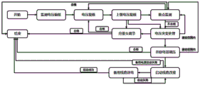
As shown in fig. 1, the method comprises the following steps:
monitoring the voltage to be low: sampling point monitoring U of main power supply line side regulation and control device (hereinafter referred to as 3# regulation and control device) A 、U B 、U C The three-phase voltage fluctuates between 190V and 198V, the time lasts for 5 minutes or more, and the microprocessor of the 3# regulation and control device generates 3And (4) early warning information that the voltage of the # zone is low, and entering a voltage rechecking link.
Voltage rechecking: transfer main power supply residual current operated circuit breaker, intelligent circuit breaker and load voltage sampling U A 、U B 、U C Three phase voltage data, data by U A 、U B 、U C Respectively added and divided by 3 to obtain a voltage U A 、U B 、U C Mean and sample point U A 、U B 、U C Comparing the voltage data to determine U A 、U B 、U C The three-phase voltage is between 190V-198V and the error is within +/-1%, and if the 3# regulation and control device is installed at the tail end of a line, the 3# section voltage is low early warning information and U A 、U B 、U C The three-phase voltage data are pushed to a main power supply public transformer substation regulation and control device (hereinafter referred to as a 1# regulation and control device) through an LORA communication channel, and a 'higher-level voltage rechecking' link is entered; otherwise U A 、U B 、U C And (3) if the three-phase voltage comparison result is lower than 187V, starting an 'upper-level voltage rechecking' link by the 3# regulation and control device immediately.
Upper-level voltage rechecking: u pushed by 3# regulation and control device and received by 1# regulation and control device A 、U B 、U C Three-phase voltage data and load voltage sampling U in the memory A 、U B 、U C Three-phase voltage data are extracted by shifting forward 5, 15, 30, 45, 60, 75, 90, 105 and 120 minutes according to the time of receiving the data A 、U B 、U C And comparing and judging the three-phase voltage data to judge whether the three-phase voltage data fluctuate within the range of 198V-208V or not, determining whether a public transformer substation provided with an on-load tap changing transformer is installed or not, and pushing 5 groups of U (U) by the 1# regulating and controlling device for 5, 15, 30, 45 and 60 minutes before the time for acquiring and receiving the data is transferred by the 1# regulating and controlling device AB 、U BC 、U AC Three-phase line voltage data is calculated according to phase voltage = line voltage ÷ 3 to obtain U A 、U B 、U C Three-phase voltage data and reporting U A 、U B 、U C Comparing the three-phase voltage data, judging whether the voltage fluctuates within the range of 198V-208V again, entering a 'tap adjustment' adjustment link, and if not, performing 'tap adjustment' againAnd the public transformer substation provided with the load tap changing transformer enters a voltage mutation processing link. Otherwise, entering a key monitoring link.
Monitoring is important: for screening U A 、U B 、U C The three-phase voltage data fluctuate for a long time in the range of 190V-198V, and the deployment points of the regulating and controlling device which appear frequently and in a short time every day are used for carrying out key monitoring; through the steps of 'voltage mutation processing' and 'parallel capacitor voltage regulation' and U A 、U B 、U C The three-phase voltage data is also mainly monitored in the fluctuation range of 190V-198V.
Adjusting a tap: the 1# regulating and controlling device reads tap gear information stored by the on-load voltage regulation controller, judges whether the on-load tap transformer meets the tap up-regulation condition, and sends a tap voltage regulation instruction to the on-load voltage regulation controller, the on-load voltage regulation controller controls the on-load voltage regulation transformer to complete tap voltage regulation, and feeds back information of whether tap regulation is successful to the 1# regulating and controlling device through the on-load voltage regulation controller, and enters a voltage rechecking link and a higher-level voltage rechecking link for voltage regulation, and then U is carried out A 、U B 、U C Checking the three-phase voltage data, if the voltage is qualified, finishing the voltage regulation; if the voltage does not meet the preset value, sending an on-load tap changer (tap) up-regulation instruction by the No. 1 regulation and control device again; otherwise, the 1# regulating and controlling device sends the information that the voltage cannot be regulated and boosted through the tap to the 3# regulating and controlling device, and the 3# regulating and controlling device enters a voltage sudden change processing link.
Voltage abrupt change treatment: if the main power supply public transformer substation is not provided with the on-load tap changing transformer or the tap joint of the on-load tap changing transformer is at the highest position, the voltage regulation cannot be met, and the 3# regulating and controlling device enters a 'parallel capacitor voltage regulation' link.
Voltage regulation by a parallel capacitor: calling intelligent capacitor switching signals by the 3# regulation and control device, and after determining that the capacitors can be put into the capacitor bank for voltage regulation, then regulating the voltage according to U A 、U B 、U C Three-phase voltage data entering sub-compensation>Supplement by different degrees>The capacitors are gradually added in the total compensation step, and after each step is finished, the load voltage sampling U is called and measured A 、U B 、U C Three-phase voltageWhether the data are in accordance with the range of 198V-208V or not, entering key monitoring, and stopping the input of the capacitor bank; if the voltage regulation condition can not be met, the capacitor bank is continuously put into operation, and after all the capacitors are put into operation, the voltage meets the standard, and the voltage regulation is finished. Otherwise, the voltage is still lower than 187V, and a 'starting circuit switching' link is started in an emergency.
Starting line switching: 3# regulating and controlling device for regulating and controlling U A 、U B 、U C Three-phase voltage data are pushed to a standby power supply public transformer substation regulating and controlling device (hereinafter referred to as a 2# regulating and controlling device) through an LORA communication channel, the 2# regulating and controlling device evaluates whether public transformer load meets the switching requirement or not, the condition meets, a 2# regulating and controlling device microprocessor sends a switching-on instruction of a standby power supply corresponding to a standby power supply residual current operated protector, and then a 3# regulating and controlling device standby power supply voltage sampling U is called up and measured A 、U B 、U C And the three-phase voltage data successfully responds to prove that the standby power supply and the power transmission are successful, the link of 'standby line power transmission' is entered, otherwise, the standby line power transmission is not successful after one retry, the 3# regulation and control device pushes the 'standby power supply starting failure' alarm information, and the line transmission is finished.
Power transmission of a standby circuit: the microprocessor of the 3# regulating and controlling device firstly sends an instruction of disconnecting the main power supply residual current operated circuit breaker, and after 3 seconds, the intelligent circuit breaker of the 3# regulating and controlling device and the load voltage sampling U are called and tested A 、U B 、U C Three phase voltage data, determining U A 、U B 、U C The voltage is 0V; then the 3# regulation and control device microprocessor sends a switching-on instruction of the standby power supply residual current operated circuit breaker, and after 3 seconds of rest, the 3# regulation and control device intelligent circuit breaker and the load voltage sampling U are called and tested again A 、U B 、U C Three-phase voltage data, and all voltages are greater than 198V and above; waiting for 3 seconds again, rechecking the intelligent circuit breaker and sampling the load voltage U again A 、U B 、U C Three-phase voltage data, and the voltage data should be more than 198V and above; and the 3# regulating and controlling device microprocessor pushes that the power supply source of the 3# regulating and controlling device is successfully switched to the standby power supply, and the line is changed and connected after the information that the load wiring position of the main power supply residual current operated circuit breaker is electrified is noticed.
According to the invention, three-level voltage regulation is carried out by an automatic voltage regulation method, so that the power supply quality of the distribution network is ensured, and the power supply reliability of the distribution network is improved.
The above-described embodiment is a preferred embodiment of the present invention, and is not intended to limit the present invention in any way, and other variations and modifications may be made without departing from the spirit and scope of the invention as defined in the appended claims.