CN115797332B - Object grabbing method and device based on instance segmentation - Google Patents
Object grabbing method and device based on instance segmentation Download PDFInfo
- Publication number
- CN115797332B CN115797332B CN202310043565.7A CN202310043565A CN115797332B CN 115797332 B CN115797332 B CN 115797332B CN 202310043565 A CN202310043565 A CN 202310043565A CN 115797332 B CN115797332 B CN 115797332B
- Authority
- CN
- China
- Prior art keywords
- target object
- grabbing
- target
- mask
- image
- Prior art date
- Legal status (The legal status is an assumption and is not a legal conclusion. Google has not performed a legal analysis and makes no representation as to the accuracy of the status listed.)
- Active
Links
Images


Abstract
The disclosure discloses an object grabbing method and device based on instance segmentation. The method comprises the following steps: acquiring an object image; performing example segmentation on the target object image by using a target object segmentation model to obtain a target object mask; calculating the center position of the target object according to the target object mask; determining the target object orientation according to the center position and the target object mask; determining a grabbing angle of the target object according to the target object orientation, so that the target object orientation corresponds to the main shaft direction of the grabbing device when the grabbing device grabs the target object at the grabbing angle; and based on the central position and the grabbing angle, indicating the grabbing device to grab the target object. According to the method, the gesture of the grabbing device can be adjusted when the target object is grabbed, so that the grabbing device grabs unified grabbing points on the target object and stacks the target object in the unified gesture, secondary gesture recognition is not needed, the gesture of the grippers is not needed to be adjusted, the operation efficiency is effectively improved, and the operation cost is reduced.
Description
Technical Field
The present disclosure relates generally to the field of image processing technology. More particularly, the present disclosure relates to an object grabbing method and apparatus based on instance segmentation.
Background
With the rise of intelligent manufacturing, the manufacturing industry gradually adopts robots and other related automation equipment to replace manual work, for example: work conveying work, and the like. In order to enable the automation equipment to smoothly grasp the target object, in some prior art, the robot needs to be taught with position points in advance, so that the robot records the current fixed carrying position, but under the scheme, the robot can grasp in a relatively fixed mode, and the situations of grabbing empty, grabbing deviation and grabbing error are easy to occur.
Therefore, in the prior art, a scheme for positioning and grabbing the target object through computer vision processing is generated, the center coordinates of the target object are positioned through image processing, and the robot is instructed to grab the target object based on the center coordinates, so that the robot is prevented from grabbing the target object in a blank, grabbing the target object in a deviated mode and grabbing the target object in a wrong mode.
However, since the object carried by the automation device may be in an irregular shape, the central coordinates of the object to be grasped are unified to prevent the occurrence of the situations of blank grasping, offset grasping and error grasping, but when the automation device places the object at the target position, the image of the grasped object needs to be acquired again and the secondary gesture recognition is performed. In addition, the hand grip posture adjustment is required to be carried out based on the recognition result, so that the object can be ensured to be stacked in order at the object position, the operation efficiency is affected, and the secondary posture recognition generates additional cost.
In view of this, it is desirable to provide an object grabbing scheme based on example segmentation, so that when the grabbing device places an object, the grabbing device can finish stacking of the object in a unified posture without secondary posture recognition and posture adjustment of the grippers, thereby improving the operation efficiency and reducing the cost.
Disclosure of Invention
To address at least one or more of the technical problems mentioned above, the present disclosure proposes, among other aspects, an object grabbing scheme based on instance segmentation.
In a first aspect, the present disclosure provides an object grabbing method based on instance segmentation, comprising: acquiring an object image; performing example segmentation on the target object image by using a target object segmentation model to obtain a target object mask; calculating the center position of the target object according to the target object mask; determining the target object orientation according to the center position and the target object mask; determining a grabbing angle of the target object according to the target object orientation, so that the target object orientation corresponds to the main shaft direction of the grabbing device when the grabbing device grabs the target object at the grabbing angle; and based on the central position and the grabbing angle, indicating the grabbing device to grab the target object.
In some embodiments, the target orientation is a direction pointing to a target edge point on the target mask at a central location; among all edge points of the target mask, the curvature radius corresponding to the target edge point is an extremum.
In some embodiments, the center position of the target is the center of gravity of the target; determining the target orientation based on the center position and the target mask includes: and traversing all edge points of the target object mask, taking the edge point with the distance from the central position as an extreme value as a target edge point, and taking the direction of the central position pointing to the target edge point as the target object direction.
In some embodiments, determining the target orientation based on the center position and the target mask includes: establishing a round window; moving the center of the round window along the edge of the target mask, and calculating the sharp parameter corresponding to each edge point; the sharpness parameters include: the center angle of the circle center of the round window corresponding to the edge point, or the superposition area of the round window and the target mask; and taking the edge point corresponding to the sharp parameter extremum as a target edge point, and taking the direction of the central position pointing to the target edge point as the target object orientation.
In some embodiments, the target orientation corresponds to a major axis direction of the grasping device, comprising: the direction of the target object is consistent with the direction of the main shaft of the grabbing device; or the relative relation of the target object orientation and the main shaft direction of the grabbing device is consistent with the preset relative relation.
In some embodiments, before calculating the center position of the target object according to the target object mask, the method further includes: and etching the target mask to update the target mask.
In some embodiments, the target image includes a left image and a right image acquired by a binocular camera; based on central point put and snatch the angle, instruct grabbing device to snatch the target object, include: calculating pixel coordinates of a preset grabbing point under an image coordinate system according to the central position; matching based on the left image and the right image to obtain depth information of a preset grabbing point; converting pixel coordinates into space coordinates under a world coordinate system by using a calibration model of the binocular camera and depth information; the gripping device is instructed to move to the spatial coordinates and grip the object at the gripping angle.
In some embodiments, matching is performed based on the left image and the right image to obtain depth information of a preset grabbing point, including: searching matching points of the left image and the right image through epipolar constraint; and calculating depth information of the preset grabbing point according to the matching point by utilizing a triangle positioning principle.
In some embodiments, the example segmentation is performed on the target object image, and before obtaining the target object mask, the method further includes: collecting target object sample images in different arrangement modes under different environments; labeling the target object sample image to form a training set; and performing model training on the example segmentation network based on the training set to obtain a target object segmentation model.
In a second aspect, the present disclosure provides an electronic device comprising: a processor; and a memory having executable code stored thereon which, when executed by the processor, causes the processor to perform the method as in the first aspect.
By the object capturing method based on example segmentation provided above, the disclosed embodiment calculates the center position of the object after the object mask is obtained by segmentation, and calculates the object orientation by using the center position and the object mask, thereby determining the capturing angle of the object. When the target objects are grabbed through the grabbing angles, the directions of the target objects correspond to the directions of the main shafts of the grabbing devices, so that when each target object is grabbed, the relative gesture of each target object and the grabbing devices are uniformly fixed, namely, the gesture of each grabbing device is adjusted when the target objects are grabbed based on the grabbing angles and the central positions, so that each grabbing device grabs the target objects at the uniform positions and can realize stacking of the target objects in the uniform gesture, secondary gesture recognition is not needed for the grabbed target objects, and the gesture of each grabbing device is not needed to be adjusted. The adjustment of the hand grip posture is completed while the target object is positioned, so that the operation efficiency is effectively improved, and the cost of image processing in operation is reduced.
Drawings
The above, as well as additional purposes, features, and advantages of exemplary embodiments of the present disclosure will become readily apparent from the following detailed description when read in conjunction with the accompanying drawings. Several embodiments of the present disclosure are illustrated by way of example, and not by way of limitation, in the figures of the accompanying drawings and in which like reference numerals refer to similar or corresponding parts and in which:
FIG. 1 illustrates an exemplary flowchart of an example segmentation-based object capture method according to an embodiment of the present disclosure;
FIG. 2 illustrates an exemplary image of some firebricks;
FIG. 3 illustrates an exemplary image of a target mask of some firebrick;
FIG. 4 illustrates an exemplary flow chart of a gripper control method of some embodiments of the present disclosure;
FIG. 5 illustrates an exemplary flow chart of a method of determining target orientation in accordance with some embodiments of the present disclosure;
FIG. 6 illustrates an exemplary flow chart of a method of determining target orientation in accordance with further embodiments of the present disclosure;
FIG. 7 is a schematic diagram illustrating a process for determining the orientation of a target in further embodiments of the present disclosure;
FIG. 8 illustrates an exemplary flow chart of a method of constructing a target segmentation model in accordance with further embodiments of the present disclosure;
fig. 9 shows an exemplary block diagram of the electronic device of an embodiment of the present disclosure.
Detailed Description
The following description of the embodiments of the present disclosure will be made clearly and fully with reference to the accompanying drawings, in which it is evident that the embodiments described are some, but not all embodiments of the disclosure. Based on the embodiments in this disclosure, all other embodiments that may be made by those skilled in the art without the inventive effort are within the scope of the present disclosure.
It should be understood that the terms "comprises" and "comprising," when used in this specification and the claims, specify the presence of stated features, integers, steps, operations, elements, and/or components, but do not preclude the presence or addition of one or more other features, integers, steps, operations, elements, components, and/or groups thereof.
It is also to be understood that the terminology used in the description of the present disclosure is for the purpose of describing particular embodiments only, and is not intended to be limiting of the disclosure. As used in the specification and claims of this disclosure, the singular forms "a", "an" and "the" are intended to include the plural forms as well, unless the context clearly indicates otherwise. It should be further understood that the term "and/or" as used in the present disclosure and claims refers to any and all possible combinations of one or more of the associated listed items, and includes such combinations.
As used in this specification and the claims, the term "if" may be interpreted as "when..once" or "in response to a determination" or "in response to detection" depending on the context. Similarly, the phrase "if a determination" or "if a [ described condition or event ] is detected" may be interpreted in the context of meaning "upon determination" or "in response to determination" or "upon detection of a [ described condition or event ]" or "in response to detection of a [ described condition or event ]".
Specific embodiments of the present disclosure are described in detail below with reference to the accompanying drawings.
Exemplary application scenarios
The traditional manual workpiece carrying operation requires workers to load workpieces, then drives and carries the workpieces to a designated position, and then manually unloads the workpieces and stacks the workpieces, so that the efficiency is low and a large amount of human resources are consumed. After automatic equipment such as a robot is introduced, the robot can automatically position a workpiece and grasp the workpiece at the central coordinate of the workpiece through position point teaching or after a computer vision processing device is additionally arranged on the robot, so that the conditions of grabbing blank, grabbing deviation and grabbing mistake are prevented, and then the robot moves to a designated position and then puts down the workpiece to finish stacking.
For the workpieces which are originally orderly arranged and/or shaped, the carrying operation can be completed through the process, and the carried workpieces can still be orderly piled up at the designated positions.
However, in an actual handling scenario, the workpieces to be handled are often not aligned or shaped, for example: there is a columnar structure in which the refractory bricks have a cross section like a water droplet, and the arrangement directions of the refractory bricks in the stack to be carried are different. Under the condition, the adoption of the robot grabbing scheme can lead to different postures of the refractory bricks on the grippers, and if the refractory bricks are required to be neatly piled at the designated positions, the image acquisition and the processing are required to be carried out again when the refractory bricks are placed, so that the postures of the refractory bricks are identified and the postures of the grippers are correspondingly adjusted.
This not only affects the efficiency of the handling operation, but also results in additional costs.
It should be noted that the above-described application scenario is merely an example provided for the convenience of understanding the present disclosure, and the solution provided by the present disclosure is not limited in this respect, that is, the solution provided by the present disclosure may be applied to any applicable scenario.
Exemplary embodiment
In view of this, the embodiment of the disclosure provides an example segmentation-based target object capturing scheme, which calculates the target object orientation through the center position of the segmented target object and the target object mask, so as to guide the capturing angle of the capturing device, so that when the capturing device captures the target object based on the capturing angle, the target object orientation corresponds to the main axis direction of the capturing device, and the relative gesture of each target object and the capturing device is ensured to be uniformly fixed when the target object is captured, so that the orderly stacking of the target object can be completed without performing secondary gesture recognition and without adjusting the gesture of the gripper, thereby effectively improving the operation efficiency and reducing the cost of image processing in the operation.
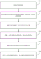
Fig. 1 illustrates an exemplary flowchart of an example segmentation-based object grabbing method according to an embodiment of the present disclosure.
As shown in fig. 1, in step 101, an image of a target object is acquired.
In some embodiments, the target image may be acquired by a binocular camera. The object image may include a plurality of objects.
In step 102, an object image is subjected to example segmentation by using the object segmentation model, and an object mask is obtained.
The object segmentation model is an example segmentation network that can distinguish between different objects based on object images and mark them with a mask.
The object segmentation model can effectively interfere the object characteristics caused by the background characteristics and the upper-layer object caused by the lower-layer object in the object image, so that the calculation of the center position and the object orientation of the subsequent object is facilitated, and the grabbing precision is improved.
In embodiments of the present disclosure, some example segmentation networks may be trained in advance with a large number of object images, such as: mask R-CNN network, etc., thereby forming a target segmentation model for the target.
In step 103, the center position of the target is calculated from the target mask.
The center position can be obtained by calculating the geometric center of the target mask. Further, for a target of uniform density, the center position may also be a gravity center position.
In some embodiments, the segmented object mask may also be subjected to an etching process to update the object mask before performing step 103.
The etching treatment is a morphological operation, which can eliminate noise points and simultaneously eliminate partial boundary values to enable the edges of the target masks to shrink inwards, firstly can remove noise points formed by false segmentation, and secondly can avoid the mutual adhesion of the two target masks, so that the edges of the target masks are finer.
In step 104, a target orientation is determined based on the center position and the target mask.
In the embodiment of the disclosure, a direction in which the center point points to the target edge point may be defined as a target object direction, where the target edge point is one edge point of the target object mask, and a curvature radius corresponding to the target edge point is an extremum among all edge points of the target object mask, for example: of all edge points of the target mask, the target edge point corresponds to the smallest or largest radius of curvature.
For ease of understanding, the exemplary description herein is directed to refractory bricks:
fig. 2 shows an exemplary image of some firebrick, and fig. 3 shows an exemplary image of some target mask of firebrick. As shown in fig. 2, since the firebrick is assumed to be columnar and has a drop-like radial cross section, the camera acquires an image of the firebrick from the radial cross section of the firebrick, and then the mask of the target object obtained by example division is also drop-like. As shown in fig. 3, the target mask has a tip and a blunt end, where the point O is the center of the target mask, the point a represents the edge point on the target mask with the smallest corresponding radius of curvature, and the point B represents the edge point on the target mask with the largest corresponding radius of curvature, so that the OA or OB direction can be taken as the target direction.
In step 105, the gripping angle of the target object is determined based on the target object orientation.
The purpose of calculating the gripping angle is to make the object orientation correspond to the main axis direction of the gripping device when the gripping device grips the object at the gripping angle.
The target object orientation and the main shaft direction of the gripping device may be the following two conditions:
firstly, the direction of a target object is consistent with the main shaft direction of the grabbing device;
secondly, the relative relation between the direction of the target object and the main shaft direction of the grabbing device is consistent with the preset relative relation, for example: the target object is oriented in a direction which is 45 degrees after the main shaft direction of the grabbing device rotates clockwise. It should be noted that the above is only an exemplary description of the preset relative relationship, and in practical application, the preset relative relationship includes a plurality of types, which are not described herein in detail.
When the grabbing angle is calculated, the grabbing angle is calculated by taking any one of the two corresponding conditions as a target.
Assuming that the target orientation is consistent with the main axis direction of the gripping device, taking the refractory bricks with the above-mentioned radial cross section in a drop-like shape as an example, when the gripping device grips the refractory bricks at the calculated gripping angle, the tip of each gripped refractory brick (defined herein that the target edge point corresponds to the smallest radius of curvature, i.e. the OA direction in fig. 3 is the target orientation) points to the main axis direction of the gripping device, so that when the gripping device places the refractory bricks in a uniform posture, the refractory bricks stacked in the designated area are aligned in the uniform direction of the tip, for example: uniformly pointing to the main shaft direction of the grabbing device.
In step 106, the gripping device is instructed to grip the object based on the center position and the gripping angle.
In embodiments of the present disclosure, the gripping device may grip the target object directly at the center position at the grip angle determined in step 105. In other embodiments, the capturing position may be a position other than the central position, for example, a preset capturing point is set, and the position of the preset capturing point is calculated based on the central position according to the relative positional relationship between the preset capturing point and the center of the target mask, so as to instruct the capturing device to capture at the capturing angle determined in step 105 at the position.
According to the object grabbing method, the object mask is obtained through example segmentation, the center position of the object is calculated, then the object orientation is calculated by utilizing the center position and the object mask, and therefore the grabbing angle of the object is determined, when the grabbing device grabs the object at the grabbing angle, the object orientation corresponds to the main shaft direction of the grabbing device, namely the relative gesture of the grabbed object and the grabbing device is uniformly fixed, and accordingly the grabbing device can achieve stacking of the object in uniform gesture. According to the target object grabbing method, the gesture of the grabbing device is adjusted when the target object is grabbed, secondary gesture recognition is not needed for the grabbed target object, the gesture of the grippers is not needed to be adjusted, the operation efficiency is effectively improved, and the cost of image processing in operation is reduced.
In addition, the scheme disclosed by the disclosure is also suitable for a conveyor belt operation scene, and by the object grabbing method, objects can be guaranteed to be placed on the conveyor belt in the same gesture, so that the consistency of the gesture of the objects entering the next process is guaranteed, the next process can be guaranteed to smoothly and orderly process the objects, and a gesture adjusting device or a gesture adjusting manual work is not required to be additionally arranged between the conveyor belt and the next process equipment.
Since the above center position is calculated based on the image of the object, it is a pixel coordinate in the pixel coordinate system, and is required to be converted into a spatial coordinate in the world coordinate system when the gripping device is instructed to perform the gripping operation, and the gripping device is controlled based on the spatial coordinate.
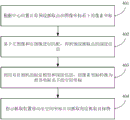
Fig. 4 illustrates an exemplary flowchart of a gripping device control method of some embodiments of the present disclosure.
As shown in fig. 4, in step 401, pixel coordinates of a preset capture point in an image coordinate system are calculated according to a center position.
In this embodiment, the preset gripping point may be set to the center position, or may be set to a position other than the center position.
The pixel coordinate system is a coordinate system introduced for describing coordinates of an image point imaged by a target object on an image, and the unit of the pixel coordinate system is a pixel point; the world coordinate system is a three-dimensional world coordinate system that is introduced to describe the location of the object in the real world and the location of the camera.
The conversion of the pixel coordinate system and the world coordinate system also involves a camera coordinate system and an image coordinate system; wherein the camera coordinate system is a coordinate system established on the camera, defined for describing the object position from the camera's perspective; the image coordinate system is introduced to describe the projected transmission relationship of the object from the camera coordinate system to the image coordinate system during imaging.
In step 402, matching is performed based on the left image and the right image, so as to obtain depth information of the preset grabbing point.
In this embodiment, the target object image includes a left image and a right image acquired by the binocular camera, parallax of the binocular camera can be determined through the left image and the right image, stereo matching of the images can be achieved by combining the parallax, the focal length of the camera and the base line of the camera, and determination of depth information of the pixel points is completed.
Illustratively, step 402 may include:
searching matching points of the left image and the right image through epipolar constraint;
and calculating depth information of the preset grabbing point according to the matching point by utilizing a triangle positioning principle.
The camera focal length and the camera base line can be obtained by calibrating the cameras so as to establish a calibration model of the binocular camera, wherein the calibration model comprises internal and external parameters and distortion parameters of the left camera and the right camera in the binocular camera, and a spatial position matrix of the left camera relative to the right camera.
In some embodiments, camera calibration may be accomplished using a Zhang Zhengyou calibration method. Specifically, the calibration step includes: collecting a calibration plate image; and finding a plurality of pixel points corresponding to the actual points one by one on the calibration plate image to form a plurality of groups of corresponding points, solving a homography matrix by using a least square method through the plurality of groups of corresponding points, taking the plurality of homography matrixes obtained by solving as constraints, solving internal and external parameters of the binocular camera, and evaluating distortion parameters of the binocular camera by using a least square method idea to obtain a calibration model.
In the calibration step, similarly, polar constraint can be adopted to match the actual point with the pixel point.
It will be appreciated that the above is merely an exemplary illustration of a camera calibration method suitable for the present disclosure, and that in practical applications, other camera calibration methods are suitable for the present disclosure, and are not limited solely herein.
In step 403, the pixel coordinates are converted to spatial coordinates in the world coordinate system using the calibration model of the binocular camera and the depth information.
In pixel coordinates For example, it is associated with the spatial coordinates in the corresponding world coordinate system>
 The conversion relation of (2) is as follows:

wherein, the liquid crystal display device comprises a liquid crystal display device, is a scale factor; />
 Is an internal reference matrix of the binocular camera; />
 Is the image distance; />
 And->
And-> Respectively->
 Direction and->
 The physical length of one pixel in the direction on the camera photosheet, i.e., the number of millimeters per pixel; />
 The offset of the origin of the image coordinate system relative to the pixel coordinate system is the coordinate of the center of the camera photosensitive plate under the pixel coordinate system; />
 Is the angle between the transverse edge and the longitudinal edge of the photosensitive plate; />
 Is the external reference matrix of the binocular camera, +.>
 For rotating matrix +.>
 Is a translation matrix.
In the above conversion process, the pixel coordinates are converted into image coordinates in the image coordinate system through affine transformation, then converted into azimuth coordinates in the camera coordinate system after perspective projection, and converted into space coordinates in the world coordinate system after rigid transformation by the external parameter matrix.
Further, in the coordinate system conversion process in the step 403, the coordinate transformation relationship between the terminal coordinate system of the grabbing device and the camera coordinate system or the coordinate transformation relationship between the base coordinate system of the grabbing device and the camera coordinate system can be solved through hand-eye calibration, so as to assist in solving the space coordinates.
The camera is fixed at the tail end of the grabbing device, the camera is fixed relative to the grabbing hand, the camera moves along with the grabbing hand, and the coordinate conversion relation between the tail end coordinate system of the industrial robot and the camera coordinate system can be solved, so that a hand-eye conversion matrix is obtained. And if the camera is fixed outside the grabbing device, the camera and the base of the grabbing device are relatively static, and the motion of the gripper has no influence on the camera, solving the coordinate transformation relation between the base coordinate system and the camera coordinate system, and obtaining the hand-eye transformation matrix.
Through the hand-eye conversion matrix, the space coordinate corresponding to the camera vision can be converted into the space coordinate corresponding to the gripper of the grabbing device.
In step 404, the gripper is instructed to move to spatial coordinates and grip the object at a gripping angle.
Through the steps 401 to 403, the spatial coordinates of the preset grabbing point in the world coordinate system can be calculated, the spatial coordinates are used for indicating the movement of the grippers of the grabbing device, and meanwhile, the gesture of the grippers can be indicated based on the grabbing angle determined by the orientation of the target object, so that the grabbing device is controlled to achieve grabbing at a unified position on the target object, and the relative gesture of the grabbed target object and the grabbing device is unified.
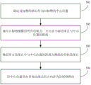
Fig. 5 illustrates an exemplary flow chart of a method of determining target orientation in accordance with some embodiments of the present disclosure. It will be appreciated that the method of determining the orientation of the target is a specific implementation of step 104 described above, and thus the features described above in connection with fig. 1 may be similarly applied thereto.
As shown in fig. 5, in step 501, the center of gravity of the target is determined as the center position of the target.
In some embodiments, the center of gravity of the target mask may be taken as the center of gravity of the target, assuming that the target mask density is uniform.
In step 502, all edge points of the object mask are traversed and the distance of the current edge point from the center position is calculated.
After the traversal is finished, the distances from all the edge points to the central position can be obtained, namely, a distance set is obtained.
In step 503, a target edge point whose distance from the center position is an extremum among all edge points is determined.
In the distance set obtained in step 502, the maximum distance or the minimum distance is searched, and the corresponding edge point is the target edge point.
Still taking the refractory brick in the previous embodiment as an example, the target edge point corresponding to the maximum distance is located at the tip of the refractory brick, and the target edge point corresponding to the minimum distance is located at the blunt end of the refractory brick.
It should be noted that, in addition to the searching method in the distance set as described above, an extremum may also be found by using a synchronous comparison method. If the distance between the current edge point and the center position is larger, the distance corresponding to the current edge point is reserved, otherwise, the current edge point is abandoned until the traversal is finished, and the only reserved edge point is the target edge point.
In step 504, the direction in which the center point points to the target edge point is taken as the target object orientation.
The above embodiments provide an exemplary target orientation determination method suitable for use in the target capture scheme of the present disclosure, and the present disclosure also provides another suitable target orientation determination method.
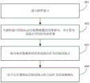
Fig. 6 illustrates an exemplary flow chart of a method of determining target orientation in accordance with further embodiments of the present disclosure. It will be appreciated that the method of determining the orientation of the target is a specific implementation of step 104 described above, and thus the features described above in connection with fig. 1 may be similarly applied thereto.
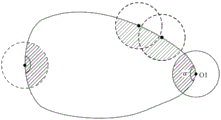
As shown in fig. 6, in step 601, a circular window is established.
In some embodiments, the radius unit of the circular window may be a pixel, and the radius of the circular window may be set according to practical situations, for example, the radius of the circular window is set to 1 to 10 pixels.
In step 602, the center of the circular window is moved along the edge of the target mask, and the sharp parameter corresponding to each edge point is calculated.
Wherein the sharpness parameters may include: the center angle of the circle center of the round window corresponding to the edge point or the coincidence area of the round window and the target mask.
In step 603, the edge point corresponding to the sharp parameter extremum is taken as the target edge point.
For ease of understanding, fig. 7 is a schematic diagram illustrating a process of determining the orientation of the object according to other embodiments of the present disclosure, as shown in fig. 7, a center O1 of the circular window moves along an edge of the object mask, and a hatched portion in fig. 7 is a coinciding portion of the circular window and the object mask, where an area of the coinciding portion may be used as a sharp parameter corresponding to the edge point, or a central angle α in fig. 7 is used as a sharp parameter corresponding to the edge point.
And recording sharp parameters corresponding to the circle center O1 of the round window when the circle center O1 of the round window is on each edge point in the process of moving along the edge of the target object mask until the traversing is finished, and taking the edge point corresponding to the maximum value or the minimum value from the plurality of sharp parameters as the target edge point.
The sharp parameters of the current edge point and the reserved edge point can be compared in the process that the circle center O1 of the round window moves along the edge of the target object mask, one edge point is reserved and the other edge point is discarded according to the determined extreme value direction until the only reserved edge point is the target edge point after traversing is finished.
In step 604, the direction in which the center point points to the target edge point is set as the target object direction.
It should be noted that, the foregoing embodiments describe two exemplary methods for determining the orientation of the target, and in practical applications, other methods for determining the orientation of the target that may be determined by those skilled in the art are also applicable to the present solution, which is not limited only herein.
Since the object capturing solution of the present disclosure requires an object image to be subjected to an instance segmentation using an object segmentation model, the instance segmentation model may also be trained in advance to obtain the object segmentation model before step 102 of the foregoing embodiment.
FIG. 8 illustrates an exemplary flow chart of a method of constructing a target segmentation model in accordance with further embodiments of the present disclosure.
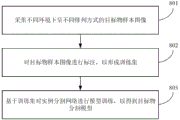
As shown in fig. 8, in step 801, sample images of targets in different arrangements under different environments are acquired.
In step 802, a target sample image is annotated to form a training set.
In step 802, a corresponding type and a pixel area of a target object may be marked in a sample image of the target object, image data with marked information is formed, and a large amount of image data with marked information is constructed into a training set.
In step 803, model training is performed on the example segmentation network based on the training set to obtain a target segmentation model.
The initial instance segmentation network can be trained by deep learning by utilizing a large amount of image data with labeling information, so that a target object segmentation model is obtained. The initial instance segmentation network may be a Mask R-CNN network.
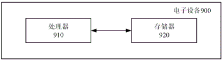
Corresponding to the foregoing functional embodiments, an electronic device as shown in fig. 9 is also provided in the embodiments of the present disclosure. Fig. 9 shows an exemplary block diagram of the electronic device of an embodiment of the present disclosure.
The electronic device 900 shown in fig. 9 includes: a processor 910; and a memory 920, the memory 920 having stored thereon executable program instructions that, when executed by the processor 910, cause the electronic device to implement any of the methods as described above.
In the electronic device 900 of fig. 9, only constituent elements related to the present embodiment are shown. Thus, it will be apparent to those of ordinary skill in the art that: the electronic device 900 may also include common constituent elements that are different from those shown in fig. 9.
Memory 920 may be used for storing hardware for various data, instructions, etc. that are processed in electronic device 900. For example, the memory 920 may store processed data and data to be processed in the electronic device 900. Memory 920 may store data sets that have been processed or to be processed by processor 910. Further, the memory 920 may store applications, drivers, etc. to be driven by the electronic device 900. The memory 920 may be a DRAM, but the present disclosure is not limited thereto. The memory 920 may include at least one of volatile memory or nonvolatile memory. The nonvolatile memory may include Read Only Memory (ROM), programmable ROM (PROM), electrically Programmable ROM (EPROM), electrically Erasable Programmable ROM (EEPROM), flash memory, phase change RAM (PRAM), magnetic RAM (MRAM), resistive RAM (RRAM), ferroelectric RAM (FRAM), and the like. Volatile memory can include Dynamic RAM (DRAM), static RAM (SRAM), synchronous DRAM (SDRAM), PRAM, MRAM, RRAM, ferroelectric RAM (FeRAM), and the like. In an embodiment, the memory 920 may include at least one of a Hard Disk Drive (HDD), a Solid State Drive (SSD), a high density flash memory (CF), a Secure Digital (SD) card, a Micro-secure digital (Micro-SD) card, a Mini-secure digital (Mini-SD) card, an extreme digital (xD) card, a cache (caches), or a memory stick.
In summary, specific functions implemented by the memory 920 and the processor 910 of the electronic device 900 provided in the embodiment of the present disclosure may be explained in comparison with the foregoing embodiments in the present disclosure, and may achieve the technical effects of the foregoing embodiments, which will not be repeated herein.
Alternatively, the present disclosure may also be implemented as a non-transitory machine-readable storage medium (or computer-readable storage medium, or machine-readable storage medium) having stored thereon computer program instructions (or computer programs, or computer instruction codes) which, when executed by a processor of an electronic device (or electronic device, server, etc.), cause the processor to perform part or all of the steps of the above-described methods according to the present disclosure.
While various embodiments of the present disclosure have been shown and described herein, it will be obvious to those skilled in the art that such embodiments are provided by way of example only. Numerous modifications, changes, and substitutions will occur to those skilled in the art without departing from the spirit and scope of the present disclosure. It should be understood that various alternatives to the embodiments of the disclosure described herein may be employed in practicing the disclosure. The appended claims are intended to define the scope of the disclosure and are therefore to cover all equivalents or alternatives falling within the scope of these claims.
Claims (8)
1. An object grabbing method based on instance segmentation is characterized by comprising the following steps:
acquiring an object image;
performing example segmentation on the target object image by using a target object segmentation model to obtain a target object mask;
calculating the center position of the target object according to the target object mask;
determining the target object orientation according to the center position and the target object mask; the target object orientation is the direction that the central position points to a target edge point on the target object mask; among all edge points of the target object mask, the curvature radius corresponding to the target edge point is an extremum;
determining a grabbing angle of the target object according to the target object orientation, so that the target object orientation corresponds to the main shaft direction of the grabbing device when the grabbing device grabs the target object at the grabbing angle;
based on the central position and the grabbing angle, indicating a grabbing device to grab a target object;
wherein said determining the target orientation based on said center position and said target mask comprises: traversing all edge points of the target object mask, taking the edge point with the distance from the central position as an extreme value as a target edge point, and taking the direction of the central position pointing to the target edge point as the target object orientation; or establishing a circular window, enabling the center of the circular window to move along the edge of the target object mask, calculating sharp parameters corresponding to each edge point, taking the edge point corresponding to the extremum of the sharp parameters as a target edge point, and taking the direction of the central position pointing to the target edge point as the target object orientation; the sharpness parameters include: and the center angle of the circle center of the round window corresponds to the center angle of the edge point, or the superposition area of the round window and the target mask.
2. The object grabbing method based on instance segmentation as claimed in claim 1, wherein,
the center position of the target object is the center of gravity of the target object.
3. The object grabbing method based on instance segmentation as claimed in claim 1, wherein,
the target object orientation corresponds to the main shaft direction of the grabbing device, and comprises:
the direction of the target object is consistent with the main shaft direction of the grabbing device;
or the relative relation between the direction of the target object and the main shaft direction of the grabbing device is consistent with the preset relative relation.
4. The object grabbing method based on instance segmentation as claimed in claim 1, wherein,
before calculating the center position of the target object according to the target object mask, the method further comprises:
and etching the target object mask to update the target object mask.
5. The object grabbing method based on instance segmentation as claimed in claim 1, wherein,
the target object image comprises a left image and a right image which are acquired by a binocular camera;
based on the center position and the grabbing angle, the instruction grabbing device grabs the target object, and the method comprises the following steps:
calculating pixel coordinates of a preset grabbing point under an image coordinate system according to the central position;
matching based on the left image and the right image to obtain depth information of the preset grabbing point;
converting the pixel coordinates into space coordinates under a world coordinate system by using a calibration model of the binocular camera and the depth information;
and indicating the grabbing device to move to the space coordinates and grabbing the target object at the grabbing angle.
6. The object capturing method based on instance segmentation according to claim 5, wherein,
the matching based on the left image and the right image to obtain the depth information of the preset grabbing point includes:
searching matching points of the left image and the right image through epipolar constraint;
and calculating the depth information of the preset grabbing point according to the matching point by utilizing a triangle positioning principle.
7. The object grabbing method based on instance segmentation as claimed in claim 1, wherein,
the example segmentation is performed on the target object image, and before the target object mask is obtained, the method further comprises the following steps:
collecting target object sample images in different arrangement modes under different environments;
labeling the target object sample image to form a training set;
and performing model training on the example segmentation network based on the training set to obtain the target object segmentation model.
8. An electronic device, comprising:
a processor; and
a memory having executable code stored thereon, which when executed by the processor, causes the processor to perform the method of any of claims 1-7.
Priority Applications (1)
| Application Number | Priority Date | Filing Date | Title |
|---|---|---|---|
| CN202310043565.7A CN115797332B (en) | 2023-01-29 | 2023-01-29 | Object grabbing method and device based on instance segmentation |
Applications Claiming Priority (1)
| Application Number | Priority Date | Filing Date | Title |
|---|---|---|---|
| CN202310043565.7A CN115797332B (en) | 2023-01-29 | 2023-01-29 | Object grabbing method and device based on instance segmentation |
Publications (2)
| Publication Number | Publication Date |
|---|---|
| CN115797332A CN115797332A (en) | 2023-03-14 |
| CN115797332B true CN115797332B (en) | 2023-05-30 |
Family
ID=85429042
Family Applications (1)
| Application Number | Title | Priority Date | Filing Date |
|---|---|---|---|
| CN202310043565.7A Active CN115797332B (en) | 2023-01-29 | 2023-01-29 | Object grabbing method and device based on instance segmentation |
Country Status (1)
| Country | Link |
|---|---|
| CN (1) | CN115797332B (en) |
Citations (3)
| Publication number | Priority date | Publication date | Assignee | Title |
|---|---|---|---|---|
| CN113420746A (en) * | 2021-08-25 | 2021-09-21 | 中国科学院自动化研究所 | Robot visual sorting method and device, electronic equipment and storage medium |
| CN114140418A (en) * | 2021-11-26 | 2022-03-04 | 上海交通大学宁波人工智能研究院 | Seven-degree-of-freedom grabbing posture detection method based on RGB image and depth image |
| WO2022073427A1 (en) * | 2020-10-10 | 2022-04-14 | 达闼机器人有限公司 | Visual positioning method and apparatus for object grabbing point, and storage medium and electronic device |
Family Cites Families (3)
| Publication number | Priority date | Publication date | Assignee | Title |
|---|---|---|---|---|
| CN104390584B (en) * | 2014-05-22 | 2018-04-06 | 北京中天荣泰科技发展有限公司 | Binocular vision laser calibration measurement apparatus and measuring method |
| CN107341802B (en) * | 2017-07-19 | 2021-02-09 | 无锡信捷电气股份有限公司 | Corner sub-pixel positioning method based on curvature and gray scale compounding |
| CN112766046A (en) * | 2020-12-28 | 2021-05-07 | 深圳市捷顺科技实业股份有限公司 | Target detection method and related device |
-
2023
- 2023-01-29 CN CN202310043565.7A patent/CN115797332B/en active Active
Patent Citations (3)
| Publication number | Priority date | Publication date | Assignee | Title |
|---|---|---|---|---|
| WO2022073427A1 (en) * | 2020-10-10 | 2022-04-14 | 达闼机器人有限公司 | Visual positioning method and apparatus for object grabbing point, and storage medium and electronic device |
| CN113420746A (en) * | 2021-08-25 | 2021-09-21 | 中国科学院自动化研究所 | Robot visual sorting method and device, electronic equipment and storage medium |
| CN114140418A (en) * | 2021-11-26 | 2022-03-04 | 上海交通大学宁波人工智能研究院 | Seven-degree-of-freedom grabbing posture detection method based on RGB image and depth image |
Also Published As
| Publication number | Publication date |
|---|---|
| CN115797332A (en) | 2023-03-14 |
Similar Documents
| Publication | Publication Date | Title |
|---|---|---|
| CN109483554B (en) | Robot dynamic grabbing method and system based on global and local visual semantics | |
| CN110238849B (en) | Robot hand-eye calibration method and device | |
| WO2019114339A1 (en) | Method and device for correcting motion of robotic arm | |
| CN111452040B (en) | System and method for associating machine vision coordinate space in a pilot assembly environment | |
| US9259844B2 (en) | Vision-guided electromagnetic robotic system | |
| CN108827154B (en) | Robot non-teaching grabbing method and device and computer readable storage medium | |
| CN112828892B (en) | Workpiece grabbing method and device, computer equipment and storage medium | |
| CN108748149B (en) | Non-calibration mechanical arm grabbing method based on deep learning in complex environment | |
| CN113379849B (en) | Robot autonomous recognition intelligent grabbing method and system based on depth camera | |
| CN106845354B (en) | Part view library construction method, part positioning and grabbing method and device | |
| CN112847375B (en) | Workpiece grabbing method and device, computer equipment and storage medium | |
| CN113284178B (en) | Object stacking method, device, computing equipment and computer storage medium | |
| CN113524187B (en) | Method and device for determining workpiece grabbing sequence, computer equipment and medium | |
| CN112164112A (en) | Method and device for acquiring pose information of mechanical arm | |
| CN111390910A (en) | Manipulator target grabbing and positioning method, computer readable storage medium and manipulator | |
| CN113172636B (en) | Automatic hand-eye calibration method and device and storage medium | |
| CN115797332B (en) | Object grabbing method and device based on instance segmentation | |
| CN112936257A (en) | Workpiece grabbing method and device, computer equipment and storage medium | |
| CN110298877A (en) | A kind of the determination method, apparatus and electronic equipment of object dimensional pose | |
| CN115810049A (en) | Marker-based pose determination method, device, equipment, medium and product | |
| CN116175542B (en) | Method, device, electronic equipment and storage medium for determining clamp grabbing sequence | |
| Fan et al. | An automatic robot unstacking system based on binocular stereo vision | |
| CN113538459B (en) | Multimode grabbing obstacle avoidance detection optimization method based on drop point area detection | |
| CN114074331A (en) | Disordered grabbing method based on vision and robot | |
| CN112184819A (en) | Robot guiding method and device, computer equipment and storage medium |
Legal Events
| Date | Code | Title | Description |
|---|---|---|---|
| PB01 | Publication | ||
| PB01 | Publication | ||
| SE01 | Entry into force of request for substantive examination | ||
| SE01 | Entry into force of request for substantive examination | ||
| CB02 | Change of applicant information |
Address after: 215129 Rooms 101, 102, 901, 902, Floor 9, Building 11, No. 198, Jialing River Road, High tech Zone, Suzhou City, Jiangsu Province Applicant after: Gaoshi Technology (Suzhou) Co.,Ltd. Address before: 215011 rooms 101, 102, 901 and 902, floor 1, building 11, 198 Jialingjiang Road, high tech Zone, Suzhou, Jiangsu Province Applicant before: Gaoshi Technology (Suzhou) Co.,Ltd. |
|
| CB02 | Change of applicant information | ||
| GR01 | Patent grant | ||
| GR01 | Patent grant |