CN115782946A - Hourglass spring for secondary vibration reduction - Google Patents
Hourglass spring for secondary vibration reduction Download PDFInfo
- Publication number
- CN115782946A CN115782946A CN202310006581.9A CN202310006581A CN115782946A CN 115782946 A CN115782946 A CN 115782946A CN 202310006581 A CN202310006581 A CN 202310006581A CN 115782946 A CN115782946 A CN 115782946A
- Authority
- CN
- China
- Prior art keywords
- rubber
- stop
- area
- mounting plate
- vibration damping
- Prior art date
- Legal status (The legal status is an assumption and is not a legal conclusion. Google has not performed a legal analysis and makes no representation as to the accuracy of the status listed.)
- Pending
Links
Images

Abstract
The invention relates to the field of vibration reduction parts of railway vehicles, and particularly provides a two-system hourglass spring for vibration reduction, which comprises a rubber body, a supporting plate and a mounting plate, wherein the rubber body is provided with air-direction vibration reduction areas extending to the mounting plate at two sides of the supporting plate; the rubber body comprises lateral bearing areas positioned on two sides of the hollow vibration damping area and a middle bearing area positioned on the inner side of the hollow vibration damping area; the outer end part of the side bearing area is connected with the mounting plate, and the middle bearing area is positioned on the inner side of the side bearing area and is connected with the support plate; the air-to-vibration reduction area is internally provided with a stop piece fixed on the mounting plate, the stop piece comprises a connecting plate and a rubber stop block, a first buffer gap and a second buffer gap are respectively arranged between the rubber stop block and the side bearing area as well as between the rubber stop block and the middle bearing area, and when bearing load, the rubber stop block is gradually close to the rubber body and contacts with the rubber body to form a stop. The invention can stop the hourglass spring through the rubber stop block and continuously support the vehicle body to continuously run when the hourglass spring fails.
Description
Technical Field
The invention relates to the technical field of vibration reduction parts of railway vehicles, in particular to a hourglass spring for secondary vibration reduction.
Background
The hourglass-shaped rubber spring is a vulcanized body formed by vulcanizing metal and rubber, and the vulcanized body is large at two ends and small in the middle and has an overall hourglass-shaped structure. The hourglass spring has a good vibration damping effect due to large elastic contraction capacity, and is widely applied to a secondary suspension device of a railway vehicle to damp and isolate vibration of a vehicle body, improve the running stability of the vehicle body and improve the riding comfort of passengers. In the prior art, the following patents relate to hourglass springs for railway vehicles or methods for adjusting the stiffness thereof:
1. the invention discloses a method for adjusting variable stiffness of an hourglass spring through hard stops and the hourglass spring, which is disclosed by the invention patent with the patent number of 202010095225.5, wherein the patent name of the invention is ' a method for adjusting the variable stiffness of the hourglass spring through the hard stops ' and an hourglass spring '. The rigidity of the hourglass rubber spring can be adjusted through the hard stop, and the variable rigidity of the hourglass rubber spring is realized.
2. The invention patent of patent number 201911035873.5 entitled "a nonlinear gradual stiffening hourglass spring" includes an upper vibration damping assembly having an upper elastomer with an upper stiffening member and an upper dilatant and a lower vibration damping assembly having a lower elastomer with a lower stiffening member and a lower dilatant. The invention can realize the non-linear gentle stiffening of the vertical direction, the longitudinal direction and the transverse direction, increase the comfortable sensation of passengers and enhance the coordination between the carriage and the bogie.
However, the above prior art still has the following problems:
1. the hourglass spring with the solid structure is usually too high in rigidity, so that riding experience is seriously influenced, and the hourglass spring is very unfavorable for the softness of vehicle running and the riding comfort of passengers when the hourglass spring runs on a curved road section or a rugged road section.
2. Meanwhile, a plurality of hard stops are arranged in one hourglass spring, so that the rigidity of the hourglass spring is increased rapidly when the hourglass spring is contacted with the hard stops, and the riding comfort and the running stability are further reduced; while a plurality of hard stops will increase the difficulty of product vulcanization and the efficiency of vulcanization.
In summary, how to design a two-series damping hourglass spring with high operation stability and strong riding comfort and a rigidity changing method thereof is a problem which needs to be solved at present.
Disclosure of Invention
The invention provides a two-system hourglass spring for vibration reduction, which aims to solve the problems and can improve the safety and stability of the running of a vehicle body and the comfort of people to take by arranging an idle vibration reduction area on a rubber body and arranging a stop piece in the idle vibration reduction area, wherein the stop piece can form a stop when the hourglass spring fails.
In order to achieve the purpose, the invention provides the following technical scheme: a secondary hourglass spring for vibration reduction comprises a rubber body, a supporting plate and a mounting plate, wherein the supporting plate and the mounting plate are respectively positioned in the middle and two end parts of the rubber body, and air-direction vibration reduction areas extending to the mounting plate are uniformly formed in the rubber body and positioned on two sides of the supporting plate; the hollow vibration damping area enables the rubber body to form a lateral bearing area positioned at two sides of the hollow vibration damping area and a middle bearing area positioned at the inner side of the hollow vibration damping area; the outer end part of the side bearing area is connected with the mounting plate, and the middle bearing area is positioned on the inner side of the side bearing area and connected with the support plate; the air is equipped with the stop member that is fixed in on the mounting panel to the damping district, is equipped with buffering clearance one and buffering clearance two between stop member and lateral part bearing area and the middle part bearing area respectively, and when bearing little load, the stop member is close to the rubber body along buffering clearance one and buffering clearance two, and when the load that bears crescent, the stop member continues to be close to and forms the backstop with the rubber body contact to the rubber body.
Preferably, the stop piece comprises a rubber stop block positioned on the outer side of the middle part of the hollow vibration damping area, and stop points D1 positioned on two sides of a central axis L1 of the hollow vibration damping area are uniformly distributed on the rubber stop block; the inner side molded surface of the side bearing area, which is close to the rubber stop block, is of an arc surface structure protruding towards the rubber stop block, and a first buffer gap is formed between a middle salient point D2 and a stop point D1 of the inner side molded surface; when bearing heavy load and the rubber stopper contacts with the side bearing area, the stopping point D1 contacts with the middle salient point D2 firstly.
Preferably, the rubber stop block comprises stop waist surfaces which are uniformly distributed on two sides of a central axis L1 of the air vibration reduction area, and the lower ends of the two stop waist surfaces are connected by a stop bottom surface which is parallel to the support plate; the connecting part of the stopping waist surface and the stopping bottom surface is transited by a first arc, and the middle point of the first arc forms a stopping point D1.
Preferably, the lower end part of the inner side molded surface is connected with the inner side of the stopping bottom surface and transits through a second arc, and a second buffer gap is formed between the second arc and the stopping bottom surface; the length H1 of a connecting line of the lower end points D3 and D4 of the inner side molded surface is 0.8-1.5 times of the length H2 of the first buffer gap.
Preferably, the backstop waist face is an inclined plane structure which gradually inclines from the mounting plate direction to the support plate direction towards the central axis L1, and an included angle alpha between the backstop waist face and the radial central line L2 of the support plate is larger than an included angle beta between the tangent of the inner side profile and the radial central line L2 of the support plate.
Preferably, the waist stopping surface is of an arc surface structure protruding towards the inner side molded surface; the curvature radius of each point on the stopping waist surface is smaller than that of each point on the inner side molded surface.
Preferably, the stop piece comprises a connecting plate fixed at the outer end of the rubber stop block; a fixing table is arranged on one side, close to the central axis L1, of the mounting plate, and a connecting table is arranged on the connecting plate and matched with the fixing table; when the installation is carried out, the connecting plate is pressed on the mounting plate, the connecting table is pressed on the fixing table, and the rubber stop block is installed in the air vibration reduction area.
Preferably, the supporting plate is of an integrated structure, and the rubber bodies are uniformly vulcanized on two sides of the supporting plate; rubber covered edges are arranged on the outer sides of the two side parts of the supporting plate and comprise end part straight surface sections and side part inclined surface sections; the thickness of the side inclined plane section is gradually increased from the outside to the inside.
Preferably, the outer molded surface of the side bearing area is a cambered surface structure protruding towards one side far away from the central axis L1; the middle salient point D5 of the outer side molded surface, the middle salient point D2 of the inner side molded surface and the stopping point D1 are positioned on the same straight line.
Preferably, the upper part of the outer side molded surface is provided with a cambered surface structure rubber bag positioned below the mounting plate, a bottom rubber coating section connected with the rubber bag is arranged below the mounting plate, and the rubber bag and the bottom rubber coating section are in three-transition through a circular arc protruding towards the central axis L1; the curvature radius of each point on the rubber bag is smaller than that of each point on the outer side molded surface and larger than that of the arc III.
The invention has the beneficial effects that:
1. the rubber stop block can enable the hourglass spring to have higher use reliability, when the external hourglass spring fails, the hourglass spring can be stopped by the internal rubber stop block, the vehicle body can continue to run, and the running stability of the vehicle body is guaranteed.
2. A first buffer gap and a second buffer gap are reserved between the rubber stop block and the rubber body, when the load in the early period is small, the rubber stop block is not in contact with the rubber body, the linear change of the rigidity in the early period can be ensured, when the load in the later period is large, the rubber stop block is in contact with the hourglass spring, the rigidity of the product rises nonlinearly, the deformation of the product under the large load can be reduced, the limit requirement of vehicle operation is met, and the riding comfort of passengers is improved.
3. The inner side molded surface of the side bearing area is of an arc-shaped surface structure protruding towards the rubber stopper, when the rubber stopper contacts the rubber body, the stopping waist surface is gradually attached to the inner side molded surface, so that the rigidity is slowly and gradually increased, and the discomfort brought to drivers and passengers due to the fact that the rigidity is suddenly increased can be avoided.
4. When the rubber stopper block is contacted with the rubber body, the stopping point D1 at the middle part of the arc of the rubber stopper block is firstly contacted with the middle convex point D2 of the side bearing area, so that the bearing stability of the rubber stopper block and the rubber body can be improved.
Drawings
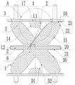
Fig. 1 is a schematic structural diagram of an hourglass spring according to an embodiment of the present invention.
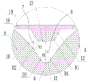
Fig. 2 is a partially enlarged schematic view at a in fig. 1.
Fig. 3 is a partially enlarged schematic view of an hourglass spring according to a second embodiment of the present invention.
Reference numerals: 1. a rubber body; 2. a support plate; 3. mounting a plate; 4. an air-direction vibration damping area; 5. a side bearing zone; 6. a middle load-bearing zone; 7. a first buffer gap; 8. a second buffer gap; 9. a rubber stopper; 10. an inner profile; 11. an outer profile; 12. a waist stopping surface; 13. a stop bottom surface; 14. a first arc; 15. a second arc; 16. arc three; 17. a connecting plate; 18. a fixed table; 19. a connecting table; 20. an end straight section; 21. a side slope section; 22. a rubber bag; 23. and a bottom encapsulated section.
Detailed Description
In order to make the objects, technical solutions and advantages of the present invention more apparent, the present invention will be described in further detail with reference to the accompanying drawings 1-3 and specific embodiments. It should be understood that the specific embodiments described herein are merely illustrative of the invention and are not to be construed as limiting the invention.
Example one
In the embodiment, as shown in fig. 1-2, a two-series hourglass spring for vibration reduction comprises a rubber body 1, a support plate 2 and a mounting plate 3, wherein the support plate 2 is of an integrated structure, the support plate 2 is located in the middle of the rubber body 1, and the rubber body 1 is uniformly vulcanized on two sides of the support plate 2; the mounting plates 3 are positioned at two end parts of the rubber body 1 and are evenly vulcanized on two sides of the supporting plate 2.
As shown in fig. 1, the rubber body 1 is uniformly provided with an idle vibration reduction region 4 extending to the mounting plate 3 at two sides of the support plate 2, and the idle vibration reduction region 4 enables the rubber body 1 to form a side bearing region 5 at two sides of the idle vibration reduction region 4 and a middle bearing region 6 at the inner side of the idle vibration reduction region 4; the lateral bearing area 5 and the middle bearing area 6 are of an integral rubber structure, the outer end part of the lateral bearing area 5 is connected with the mounting plate 3, and the middle bearing area 6 is located on the inner side of the lateral bearing area 5 and connected with the support plate 2.
As shown in fig. 1, a stopper fixed on the mounting plate 3 is arranged in the air-direction vibration damping region 4, a first buffer gap 7 and a second buffer gap 8 are respectively arranged between the stopper and the side bearing region 5 and the middle bearing region 6, when the stopper bears a small load, the stopper approaches to the rubber body 1 along the first buffer gap 7 and the second buffer gap 8, and when the borne load is gradually increased, the stopper continues to approach to the rubber body 1 and contacts with the rubber body 1 to form a stopper.
As shown in fig. 1 and 2, the stopper comprises a rubber stopper 9 positioned outside the middle of the hollow vibration damping region 4 and a connecting plate 17 vulcanized and fixed at the outer end of the rubber stopper 9; a fixing table 18 is arranged on one side, close to the central axis L1 of the air-direction vibration damping area 4, of the mounting plate 3, namely close to the central axis L1 of the hourglass spring, and a connecting table 19 is arranged on the connecting plate 17 in a matched manner with the fixing table 18; during installation, the connecting plate 17 is press-fitted onto the mounting plate 3 with interference and the connecting table 19 is pressed onto the fastening table 18, with the rubber stop block 9 being installed into the free damping region 4.
The rubber stop block 9 comprises stop waist surfaces 12 which are uniformly distributed on two sides of a central axis L1 of the air vibration damping region 4, the lower ends of the two stop waist surfaces 12 are connected by a stop bottom surface 13 which is parallel to the support plate 2, and the connection part of the stop waist surface 12 and the stop bottom surface 13 is transited by an arc I14; the rubber stop block 9 is uniformly provided with stop points D1 positioned on two sides of the central axis L1, and the middle point of the first arc 14 forms the stop points D1.
An inner side molded surface 10 of the side bearing area 5 close to the rubber stopper 9 is of an arc-shaped surface structure protruding towards the rubber stopper 9, and a buffer gap I7 is formed between a middle salient point D2 and a stopping point D1 of the inner side molded surface 10; when bearing heavy load and rubber backstop piece 9 and lateral part bearer region 5 contact, backstop point D1 contacts with middle part bump D2 earlier, and the middle part contact can improve the stability that rubber backstop piece 9 and lateral part bearer region 5 were loaded, and a buffering clearance 7 can avoid rubber backstop piece 9 to contact with rubber body 1 at once and increase rigidity when little load, can improve the travelling comfort that the passenger took when guaranteeing automobile body operation security.
As shown in fig. 2, the lower end part of the inner side molded surface 10 is connected at the inner side of the stop bottom surface 13 and transits through the second arc 15, a buffer gap second 8 is arranged between the middle part of the second arc 15 and the stop bottom surface 13, when bearing a large load, the rubber stop block 9 can be designed to be in contact with the second arc 15 and further form a stop, or even when entering a limit load stage, the rubber stop block 9 is not in contact with the second arc 15, only the stop waist surface 12 is in contact with the inner side molded surface 10, at this time, the rigidity is not increased, and the vehicle body can be supported to continue to run; in the present embodiment, it is preferable to design the rubber stopper 9 so as not to contact the second arc 15 even when the limit load stage is entered; the length H1 of a connecting line of the lower end points D3 and D4 of the inner side profiles 10 is 0.8-1.5 times of the length H2 of the first buffer gap 7, so that the condition that the inner side profiles 10 are contacted when bearing small load and affecting the service performance of the product when the distance between the inner side profiles 10 is too narrow is avoided, or the condition that the rubber stop block 9 cannot be contacted with the inner side profiles 10 even when bearing large load and affecting the service performance of the product when the distance between the inner side profiles 10 is too wide is avoided.
As shown in fig. 1, rubber covered edges are arranged on the outer sides of two side parts of the support plate 2, and the rubber covered edges can prevent corrosion and dust, so that the service life of a product is prolonged; the rubber wrapping comprises an end straight section 20 and a side inclined section 21; the thickness of the side inclined surface section 21 is gradually increased from outside to inside, and meanwhile, the outer molded surface 11 of the side bearing area 5 is of a cambered surface structure protruding towards one side far away from the central axis L1; when the rubber body is deformed so that the outer profile 11 of the side bearing zone 5 is in contact with the side inclined surface section 21, the outer profile 11 can gradually approach the side inclined surface section 21 to improve the rigidity; the middle salient point D5 of the outer side molded surface 11, the middle salient point D2 of the inner side molded surface 10 and the stopping point D1 are located on the same straight line, and the overall supporting stability of the hourglass spring can be improved.
As shown in fig. 1, a rubber bag 22 with a cambered surface structure is arranged on the upper part of the outer molded surface 11 and is positioned below the mounting plate 3, a bottom rubber coating section 23 connected with the rubber bag 22 is arranged below the mounting plate 3, the bottom rubber coating section 23 can be drained, dustproof and anticorrosive, and the service life of the mounting plate 3 is prolonged; the rubber packet 22 and the bottom rubber-coated section 23 are transited through a circular arc III 16 protruding towards the central axis L1; the curvature radius of each point on the rubber bag 22 is smaller than that of each point on the outer side molded surface 11 and is larger than that of the arc three 16; that is, the rubber bag 22 protrudes more to the side far from the central axis L1 relative to the outer profile 11, and when a large load is applied to make the mounting plate 3 contact the rubber body 1, the rubber bag 22 can improve the stability of supporting the mounting plate 3; for rubber package 22, circular arc three 16 is protruding towards axis L1 one side greatly, can prevent that rubber profile fold between rubber package 22 and the encapsulated section 23 of bottom from warping when the rubber warp, improves the life of rubber.
Example two
In the embodiment shown in fig. 3, the waist-stopping surface 12 is a cambered surface structure protruding towards the inner profile 10; the curvature radius of each point on the backstop waist surface 12 is smaller than that of each point on the inner side molded surface 10, so that the rapid decrease of rigidity when the backstop waist surface 12 is in contact with the inner side molded surface 10 can be further reduced, and the stability and the comfort are improved.
While embodiments of the present invention have been shown and described above, it should be understood that the above embodiments are exemplary and should not be taken as limiting the invention. Variations, modifications, substitutions and alterations of the above-described embodiments may be made by those of ordinary skill in the art without departing from the scope of the present invention.
The above embodiments of the present invention should not be construed as limiting the scope of the present invention. Any other corresponding changes and modifications made according to the technical idea of the present invention should be included in the protection scope of the claims of the present invention.
Claims (10)
1. A hourglass spring for secondary vibration reduction comprises a rubber body (1), a supporting plate (2) and a mounting plate (3), wherein the supporting plate (2) and the mounting plate (3) are respectively positioned in the middle and two end parts of the rubber body (1), and is characterized in that air-direction vibration reduction areas (4) extending to the mounting plate (3) are uniformly formed in the rubber body (1) and positioned on two sides of the supporting plate (2); the hollow vibration damping area (4) enables the rubber body (1) to form a side bearing area (5) positioned at two sides of the hollow vibration damping area (4) and a middle bearing area (6) positioned at the inner side of the hollow vibration damping area (4); the outer end part of the side bearing area (5) is connected with the mounting plate (3), and the middle bearing area (6) is positioned on the inner side of the side bearing area (5) and is connected with the support plate (2); the air direction is provided with a stop part fixed on the mounting plate (3) in the vibration reduction area (4), a first buffer gap (7) and a second buffer gap (8) are respectively arranged between the stop part and the side bearing area (5) and the middle bearing area (6), when bearing small load, the stop part is close to the rubber body (1) along the first buffer gap (7) and the second buffer gap (8), and when the bearing load is gradually increased, the stop part continues to be close to the rubber body (1) and contacts with the rubber body (1) to form a stop.
2. The hourglass spring for damping secondary vibration according to claim 1, wherein the stop piece comprises a rubber stop block (9) which is positioned outside the middle of the idle vibration damping area (4), and stop points D1 which are positioned on two sides of a central axis L1 of the idle vibration damping area (4) are uniformly distributed on the rubber stop block (9); an inner side molded surface (10) of the side bearing area (5) close to the rubber stop block (9) is of an arc surface structure protruding towards the rubber stop block (9), and a buffer gap I (7) is formed between a middle salient point D2 of the inner side molded surface (10) and a stop point D1; when a large load is borne and the rubber stop block (9) is in contact with the side bearing area (5), the stop point D1 is firstly in contact with the middle salient point D2.
3. The hourglass spring for secondary vibration damping according to claim 2, wherein the rubber stop block (9) comprises stop waist surfaces (12) which are uniformly distributed on two sides of a central axis L1 of the hollow vibration damping region (4), and the lower ends of the two stop waist surfaces (12) are connected by a stop bottom surface (13) which is parallel to the support plate (2); the connecting part of the stopping waist surface (12) and the stopping bottom surface (13) is transited by a first arc (14), and the middle point of the first arc (14) forms a stopping point D1.
4. The hourglass spring for secondary vibration damping according to claim 2, wherein the lower end of the inner profile (10) is connected to the inner side of the stop bottom surface (13) and transits through a second arc (15), and a second buffer gap (8) is formed between the second arc (15) and the stop bottom surface (13); the length H1 of a connecting line of lower end points D3 and D4 of the inner side molded surface (10) is 0.8-1.5 times of the length H2 of the first buffer gap (7).
5. Hourglass spring for secondary vibration damping according to claim 4, characterized in that the stop surface (12) is a sloping surface structure that slopes gradually towards the central axis L1 from the mounting plate (3) towards the support plate (2), and the angle α between the stop surface (12) and the radial centre line L2 of the support plate (2) is larger than the angle β between the tangent of the inner profile (10) and the radial centre line L2 of the support plate (2).
6. Hourglass spring for secondary damping according to claim 4, characterized in that the stop waist surface (12) is a curved surface structure protruding towards the inner profile (10); the curvature radius of each point on the stopping waist surface (12) is smaller than that of each point on the inner side molded surface (10).
7. Hourglass spring for secondary vibration damping according to claim 5 or 6, characterized in that the stop comprises a connecting plate (17) fixed to the outer end of the rubber stop block (9); a fixing table (18) is arranged on one side, close to the central axis L1, of the mounting plate (3), and a connecting table (19) is arranged on the connecting plate (17) in a matched manner with the fixing table (18); when in installation, the connecting plate (17) is pressed on the mounting plate (3) and presses the connecting platform (19) on the fixing platform (18), and the rubber stop block (9) is installed in the air damping area (4).
8. The hourglass spring for secondary vibration damping according to claim 7, wherein the support plate (2) is of an integral structure, and the rubber body (1) is uniformly vulcanized on two sides of the support plate (2); rubber covered edges are arranged on the outer sides of two side parts of the supporting plate (2), and each rubber covered edge comprises an end part straight surface section (20) and a side part inclined surface section (21); the side slope section (21) gradually increases in thickness from the outside to the inside.
9. Hourglass spring for secondary damping according to claim 8, characterized in that the outer profiles (11) of the side bearing zones (5) are of a cambered structure protruding towards the side facing away from the centre axis L1; the middle salient point D5 of the outer side molded surface (11), the middle salient point D2 of the inner side molded surface (10) and the stopping point D1 are positioned on the same straight line.
10. The hourglass spring for secondary vibration damping according to claim 9, wherein a cambered-structure rubber bag (22) is arranged on the upper portion of the outer profile (11) and is positioned below the mounting plate (3), a bottom rubber wrapping section (23) connected with the rubber bag (22) is arranged below the mounting plate (3), and the rubber bag (22) and the bottom rubber wrapping section (23) are transited through a circular arc three (16) protruding towards the central axis L1; the curvature radius of each point on the rubber bag (22) is smaller than that of each point on the outer side molded surface (11) and larger than that of the circular arc III (16).
Priority Applications (1)
| Application Number | Priority Date | Filing Date | Title |
|---|---|---|---|
| CN202310006581.9A CN115782946A (en) | 2023-01-04 | 2023-01-04 | Hourglass spring for secondary vibration reduction |
Applications Claiming Priority (1)
| Application Number | Priority Date | Filing Date | Title |
|---|---|---|---|
| CN202310006581.9A CN115782946A (en) | 2023-01-04 | 2023-01-04 | Hourglass spring for secondary vibration reduction |
Publications (1)
| Publication Number | Publication Date |
|---|---|
| CN115782946A true CN115782946A (en) | 2023-03-14 |
Family
ID=85428529
Family Applications (1)
| Application Number | Title | Priority Date | Filing Date |
|---|---|---|---|
| CN202310006581.9A Pending CN115782946A (en) | 2023-01-04 | 2023-01-04 | Hourglass spring for secondary vibration reduction |
Country Status (1)
| Country | Link |
|---|---|
| CN (1) | CN115782946A (en) |
-
2023
- 2023-01-04 CN CN202310006581.9A patent/CN115782946A/en active Pending
Similar Documents
| Publication | Publication Date | Title |
|---|---|---|
| US5176083A (en) | Railroad car truck damping member with open cavity and support rib construction | |
| US3904181A (en) | Fluid type accumulator spring with emergency back-up spring | |
| US6591759B2 (en) | Pedestal shear pad | |
| CN107701642B (en) | Pre-pressing type emergency air spring assembly | |
| CN107740837B (en) | Emergency air spring assembly | |
| CN107740832B (en) | Pre-pressing type emergency air spring assembly | |
| CA1165181A (en) | Secondary suspension system for a railway car | |
| RU2745464C1 (en) | Hourglass-type pneumatic element | |
| CN114001117B (en) | Combined rubber joint for improving transverse stability of air spring | |
| AU2010353129B2 (en) | Empty-weight two-stage frictional lower side bearing for use in railway freight car bogie | |
| US4428302A (en) | Emergency spring system for a railway car | |
| CN115782946A (en) | Hourglass spring for secondary vibration reduction | |
| KR880000849B1 (en) | Side bearing for a railway car | |
| US2907282A (en) | Rail vehicle suspension | |
| CN210133119U (en) | Rigidity-adjustable transverse elastic stop on anti-rolling torsion bar | |
| CN113969956B (en) | Method for improving lateral stability of air spring | |
| CN210423551U (en) | Pre-compression air spring system | |
| JPH0958239A (en) | Vehicular suspension | |
| CN111301462A (en) | Railway wagon bogie with normal friction and variable friction wedge damping performance | |
| CN113719580B (en) | Method for improving service performance of transverse backstop | |
| CN113059972A (en) | Lightweight suspension device | |
| CN210822269U (en) | Elastic anti-side rolling device of railway wagon | |
| JP2006057746A (en) | Axial spring device | |
| CN212828388U (en) | Damping device for railway vehicle | |
| CN205086937U (en) | Axle box longitudinal elastic pad |
Legal Events
| Date | Code | Title | Description |
|---|---|---|---|
| PB01 | Publication | ||
| PB01 | Publication | ||
| SE01 | Entry into force of request for substantive examination | ||
| SE01 | Entry into force of request for substantive examination |