CN115782102A - Injection mold easy to dissipate heat and method - Google Patents
Injection mold easy to dissipate heat and method Download PDFInfo
- Publication number
- CN115782102A CN115782102A CN202310065295.XA CN202310065295A CN115782102A CN 115782102 A CN115782102 A CN 115782102A CN 202310065295 A CN202310065295 A CN 202310065295A CN 115782102 A CN115782102 A CN 115782102A
- Authority
- CN
- China
- Prior art keywords
- air
- mold
- heat dissipation
- guide
- wind
- Prior art date
- Legal status (The legal status is an assumption and is not a legal conclusion. Google has not performed a legal analysis and makes no representation as to the accuracy of the status listed.)
- Granted
Links
Images


Classifications
-
- Y—GENERAL TAGGING OF NEW TECHNOLOGICAL DEVELOPMENTS; GENERAL TAGGING OF CROSS-SECTIONAL TECHNOLOGIES SPANNING OVER SEVERAL SECTIONS OF THE IPC; TECHNICAL SUBJECTS COVERED BY FORMER USPC CROSS-REFERENCE ART COLLECTIONS [XRACs] AND DIGESTS
- Y02—TECHNOLOGIES OR APPLICATIONS FOR MITIGATION OR ADAPTATION AGAINST CLIMATE CHANGE
- Y02P—CLIMATE CHANGE MITIGATION TECHNOLOGIES IN THE PRODUCTION OR PROCESSING OF GOODS
- Y02P70/00—Climate change mitigation technologies in the production process for final industrial or consumer products
- Y02P70/10—Greenhouse gas [GHG] capture, material saving, heat recovery or other energy efficient measures, e.g. motor control, characterised by manufacturing processes, e.g. for rolling metal or metal working
Landscapes
- Moulds For Moulding Plastics Or The Like (AREA)
Abstract
The invention discloses an injection mold easy to radiate heat and a method thereof, wherein the injection mold comprises a mold base, a fixed mold component and a movable mold component, two pieces of square iron which are arranged in parallel are arranged between the mold base and the fixed mold component, guide sleeves which penetrate through the fixed mold component are arranged at the positions of four corners of the mold base, the movable mold component is arranged at one side of the fixed mold component far away from the mold base, guide rods which are distributed in a matrix shape are arranged on the mold base, the same thimble bottom plate is arranged on the guide rods in a sliding mode, a plurality of thimbles are arranged on the thimble bottom plate, a thimble hole for a thimble to penetrate through is arranged on the fixed mold component, and an active radiating component is arranged on the fixed mold component. The invention carries out uniform blowing cooling on the surface of the injection molding workpiece, is beneficial to uniformly and rapidly cooling the injection molding workpiece, accelerates the separation of the injection molding workpiece from a mold, can adjust the blowing direction by combining the rack in the process of mold opening, and has ingenious structure and good linkage effect.
Description
Technical Field
The invention relates to the technical field of injection molds, in particular to an injection mold easy to radiate and a method.
Background
Injection molding is a method for producing and molding industrial products. The products are generally produced by rubber injection molding and plastic injection molding. The injection molding can also be divided into injection molding and die casting; the injection molding types are as follows: 1. rubber injection molding is a production method for directly injecting rubber material into a mold from a machine barrel for vulcanization. The rubber injection molding has the advantages that although the rubber injection molding is operated intermittently, the molding period is short, the production efficiency is high, the blank preparation procedure is cancelled, the labor intensity is low, and the product quality is excellent; 2. plastic injection molding, which is a method for plastic products, molten plastic is injected into a plastic product mold by pressure and is cooled and molded to obtain various plastic parts. There are mechanical injection molding machines that are specifically used for injection molding. The most commonly used plastics at present are polyethylene, polypropylene, ABS, PA, polystyrene, etc.; 3. injection molding, the resulting shape is often the final product and no further processing is required prior to installation or use as the final product. Many details, such as bosses, ribs, threads, can be formed in a single injection molding operation.
Injection molding, also known as injection molding, is a method of molding by injection and molding. The injection molding method has the advantages of high production speed, high efficiency, automation of operation, various colors, various shapes from simple to complex, small sizes, accurate product size, easy replacement of products, capability of forming products with complex shapes, and suitability for the molding processing fields of mass production, products with complex shapes and the like. Stirring the completely molten plastic material by a screw at a certain temperature, injecting the plastic material into a mold cavity by high pressure, and cooling and solidifying to obtain a molded product. The method is suitable for batch production of parts with complex shapes, is one of important processing methods, the injection mold is an important part for plastic molding, and in order to realize rapid shaping of plastic in the mold, the injection mold needs to be cooled in time so as to realize better cooling molding of injection molded workpieces.
Most of the existing injection molds rely on self heat conduction or a single water-cooling mode for cooling and radiating, and do not have the function of actively cooling and radiating the workpiece, so that the workpiece sometimes does not shrink in time and is not easy to demould, and the injection mold and the method which are easy to radiate are provided.
Disclosure of Invention
Based on the technical problems in the background art, the invention provides an injection mold easy to dissipate heat and a method.
The invention provides an injection mold easy to dissipate heat, which comprises a mold base, a fixed mold component and a movable mold component, wherein two pieces of square iron arranged in parallel are arranged between the mold base and the fixed mold component, guide sleeves penetrating through the fixed mold component are arranged at the positions of four corners of the mold base, the movable mold component is arranged at one side of the fixed mold component far away from the mold base, guide rods distributed in a matrix are arranged on the mold base, the guide rods are provided with a same thimble bottom plate in a sliding manner, a plurality of thimbles are arranged on the thimble bottom plate, a thimble hole for the thimble to penetrate is arranged on the fixed mold component, an active heat dissipation component is arranged on the fixed mold component and comprises a movable support arranged between the fixed mold component and the mold base, connecting blocks are arranged at the upper part and the lower part of the movable support, heat dissipation blowing components are fixedly arranged on the two connecting blocks, a first spring is sleeved between the guide sleeves and the fixed mold component close to the movable support and the fixed mold component, the heat dissipation blowing component comprises a wind guide cylinder, wind guide covers communicated with the two sides of the wind guide cylinder are arranged at two sides of the wind cylinder, the wind cylinder are flush with the wind cylinder, the two wind cylinder fixing rack parts are respectively arranged at two ends of the wind cylinder, and the wind cylinder fixing rack parts are respectively communicated with the wind cylinder, and the wind cylinder fixing rack parts are respectively communicated with the wind cylinder.
In the process of die sinking and die assembly, the rack is driven to move along with the movement of the movable die assembly, so that the gear and the air distributing cylinder are driven to rotate, the orientation of the strip-shaped channel is adjusted, and the direction of air blowing is changed.
As a further optimization of the technical scheme, the injection mold and the method for easily dissipating heat provided by the invention comprise a fixed mold assembly, wherein the fixed mold assembly comprises a fixed mold base, a mold body is embedded in the fixed mold base, and a heat dissipation body is arranged on one side of the fixed mold base, which is close to the mold base.
As a further optimization of the technical scheme, according to the injection mold and the method for easily dissipating heat provided by the invention, the side of the heat dissipation body, which is far away from the fixed mold base, is provided with the air guide grooves corresponding to the active heat dissipation assemblies, and the air guide grooves are internally provided with the heat dissipation fin grooves distributed at equal intervals.
As a further optimization of the technical scheme, the injection mold and the method for easily dissipating heat provided by the invention have the advantages that the air guide assemblies which are symmetrically distributed are arranged on one side of the fixed mold base close to the movable mold assembly, each air guide assembly comprises a slot which is formed in the fixed mold base, an insertion block is inserted into the slot, an air guide hole is formed in the insertion block, a plurality of metal columns are arranged in the slot, circular grooves matched with the metal columns are formed in the insertion block, a second spring is sleeved on the outer circumferential surface of each metal column, and a rectangular ventilation opening communicated with the inside of the slot is formed in the side wall of the fixed mold base.
In the preferred scheme, the air flow can penetrate through the rectangular ventilation opening to enter the slot, and the insertion block is ejected out under the action of the second spring under the condition that the insertion block is not extruded by the movable mold assembly, so that the rectangular ventilation opening is communicated with the air guide hole, the air flow can penetrate through the air guide hole to blow towards the injection molding workpiece, and the method for limiting the falling of the insertion block can be to arrange a limiting positioning pin in the slot and arrange a slide way capable of accommodating the positioning pin on the insertion block.
As a further optimization of the technical scheme, the injection mold and the method for easily dissipating heat provided by the invention have the advantages that the air distribution cylinder is internally provided with the liquid supply pipe, the liquid supply pipe comprises the spiral part arranged inside the air distribution cylinder, one end of the liquid supply pipe penetrates out from the side wall of the air inlet cylinder, the other end of the liquid supply pipe penetrates out from one end, far away from the air inlet cylinder, of the air distribution cylinder, the heat dissipation body is internally provided with the liquid guide channel, and one end, far away from the air inlet cylinder, of the liquid supply pipe is communicated with one end of the liquid guide channel.
In this preferred scheme, through letting in the coolant liquid, can cool down the radiator to the air current passes the in-process of spiral portion, also can cool down the air current.
As a further optimization of the technical scheme, the injection mold and the method for easily dissipating heat provided by the invention have the advantages that the air duct is internally provided with the air distribution cover, the diameter of the air distribution cover close to one end of the air inlet duct is larger than that of the other end of the air distribution cover, the side of the air distribution cover close to the strip-shaped channel is provided with the air outlet grooves, and the gaps of the air outlet grooves are sequentially reduced towards one end of the air inlet duct.
In the preferred scheme, under the action of the air distribution hood and the air outlet groove, the air flow flowing in can be more uniformly released from the strip-shaped channel.
As a further optimization of the technical scheme, the injection mold and the method easy to dissipate heat provided by the invention comprise the movable mold assembly and the movable mold base, wherein the four corner positions of the water port plate close to one side of the fixed mold assembly are respectively provided with the movable mold positioning columns, the movable mold positioning columns penetrate through the movable mold base, the movable mold base is fixedly connected with the water port plate, the movable mold positioning columns correspond to the guide sleeves, and the water port is fixed at the middle position of the water port plate.
As a further optimization of the technical scheme, the injection mold and the method for easily dissipating heat are provided, wherein the lower part of the air guide cover close to one side of the movable mold component is provided with an air guide cover plate, the air guide cover plate is provided with a first air opening and a second air opening which are distributed in parallel, an inclined air distribution tongue plate is arranged at a position of the air guide cover plate close to the position between the first air opening and the second air opening, and the inclined air distribution tongue plate is inclined to one side of the air guide cylinder.
A heat dissipation method of an injection mold easy to dissipate heat comprises the following steps:
s1: the cooling is carried out by closing the dies, liquid supply pipes in the two groups of radiating and blowing components are connected in series to a circulating pipeline of cooling liquid, the dies are cooled by flowing through the liquid supply pipes and a liquid guide channel in the radiating body, meanwhile, air flow is blown in through an air inlet cylinder, the air flow passes through the strip-shaped channel under the action of an air distributing cylinder, the air flow is blown to the air guide grooves through the air guide cylinder and the air guide cover, and the radiating fin grooves are matched for carrying out blowing and radiating on the radiating body;
s2: opening the mold to cool, driving the rack to move along with the movement of the movable mold component after opening the mold, so as to drive the gear on the air distribution cylinder to rotate, thereby adjusting the orientation of the strip-shaped channel on the air cylinder, enabling the air flow to pass through the air guide cover close to one side of the movable mold component, and blowing the air flow to the injection molding workpiece through the rectangular ventilation opening and the air guide hole without the extrusion of the movable mold component, so as to cool the injection workpiece and facilitate the smooth demolding of the injection workpiece;
s3: drawing of patterns cooling through controlling the injection molding machine, drives the activity of thimble bottom plate, drives the movable support and removes to change the position of heat dissipation subassembly of blowing, then the second wind gap aligns with the rectangle vent on the radiator in the subassembly of blowing of dispelling the heat, and partial air current then passes first wind gap, blows to the workpiece surface, carries out quick cooling to the work piece, makes the even shrink of work piece, finally breaks away from the mould.
In conclusion, the beneficial effects of the invention are as follows:
1. the invention provides an injection mold and a method easy for heat dissipation, wherein a heat dissipation blowing component is arranged and is combined with a liquid supply pipe and a heat dissipation body, so that the mold can be actively cooled, the injection molding piece can be rapidly shaped in the mold, meanwhile, a movable support is arranged in a matching way and is linked with an ejector pin bottom plate, and the position of the heat dissipation blowing component is movably adjusted while the ejector pin ejects the material, so that the surface of the injection molding piece is uniformly blown and cooled, the injection molding piece can be uniformly and rapidly cooled, the separation of the injection molding piece from the mold is accelerated, the blowing direction can be adjusted by combining a rack through the mold opening process, the structure is ingenious, the linkage effect is good, and the air distribution hood and an air outlet groove are combined, so that the uniform release of air flow is facilitated, and the spiral part can also carry out certain cooling on the air flow;
2. the air flow can pass through the rectangular ventilation opening and enter the slot, and the insert block is ejected out under the action of the second spring under the condition that the insert block is not extruded by the movable mold assembly, so that the rectangular ventilation opening is communicated with the air guide hole, the air flow can pass through the air guide hole and blow towards an injection molding workpiece, and the method for limiting the insert block to fall off can be to arrange a limiting positioning pin in the slot and arrange a slide way capable of accommodating the positioning pin on the insert block;
3. the diameter of one end, close to the air inlet cylinder, of the air distribution cover is larger than that of the other end of the air distribution cover, an air outlet groove is formed in one side, close to the strip-shaped channel, of the air distribution cover, the gap of the air outlet groove is sequentially reduced towards one end of the air inlet cylinder, and airflow can be released more uniformly from the strip-shaped channel under the action of the air distribution cover and the air outlet groove;
4. the injection molding machine is controlled to drive the ejector pin bottom plate to move, the movable support is driven to move, the position of the heat dissipation blowing assembly is changed, then the second air port in the heat dissipation blowing assembly is aligned with the rectangular ventilation opening in the heat dissipation body, partial air flow penetrates through the first air port and blows to the surface of a workpiece, the workpiece is rapidly cooled, the workpiece is made to shrink uniformly, and finally the workpiece is separated from the mold.
Drawings
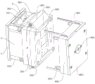
FIG. 1 is a schematic structural diagram of an injection mold easy to dissipate heat according to the present invention;
FIG. 2 is an exploded view of an injection mold with easy heat dissipation according to the present invention;
FIG. 3 is a schematic structural view of an injection mold base and a movable support for easy heat dissipation according to the present invention;
FIG. 4 is a schematic structural diagram of an active heat dissipation assembly and a fixed mold assembly of an injection mold easy to dissipate heat according to the present invention;
FIG. 5 is a schematic structural diagram of a cooling blower assembly of an injection mold with easy heat dissipation according to the present invention;
fig. 6 is a schematic structural view of an injection mold air guide cover plate easy to dissipate heat according to the present invention;
FIG. 7 is a schematic structural view of the easy-to-dissipate air distribution hood of the air distribution barrel of the injection mold according to the present invention;
FIG. 8 is a schematic structural view of an easy-to-dissipate air-separating duct of an injection mold according to the present invention;
FIG. 9 is a schematic structural view of a cooling-prone air distribution cover of an injection mold according to the present invention;
FIG. 10 is a schematic structural view of an easy heat dissipation injection mold clamping assembly in accordance with the present invention;
FIG. 11 is a schematic structural diagram of a heat sink of an injection mold easy to dissipate heat according to the present invention;
FIG. 12 is a schematic structural view of an easy-to-dissipate insert for an injection mold according to the present invention;
fig. 13 is a schematic structural view of an air duct and an air guiding cover of an injection mold easy to dissipate heat according to the present invention.
In the figure: 1. a die holder; 101. a guide rod; 102. a guide sleeve; 2. square iron; 3. a thimble base plate; 301. a thimble; 4. an active heat dissipation assembly; 401. a movable support; 40101. connecting blocks; 402. a heat dissipation blowing assembly; 40201. an air duct; 40202. a wind scooper; 40203. an air guide cover plate; 402031, a first tuyere; 402032, a second tuyere; 402033 and a wind distributing tongue plate; 40204. a liquid supply tube; 402041, helix; 40205. an air inlet cylinder; 40206. a wind distributing cylinder; 402061, wind cylinder; 402062, gear; 40207. a wind distribution cover; 402071, air outlet groove; 403. a first spring; 404. a rack; 5. a fixed die assembly; 501. a heat sink; 5011. a wind guide groove; 5012. a heat dissipation fin slot; 502. fixing a die holder; 503. a slot; 50301. a second spring; 50302. a metal post; 504. inserting a block; 50401. a wind guide hole; 505. a rectangular vent; 6. a movable die assembly; 601. a movable mold positioning column; 602. a movable die holder; 603. a water gap plate; 604. a water gap.
Detailed Description
The technical solutions in the embodiments of the present invention will be clearly and completely described below with reference to fig. 1 to 13 in the embodiments of the present invention, and it is obvious that the described embodiments are only a part of the embodiments of the present invention, and not all embodiments. All other embodiments, which can be derived by a person skilled in the art from the embodiments given herein without making any creative effort, shall fall within the protection scope of the present invention.
An injection mold easy to radiate heat comprises a mold base 1, a fixed mold component 5 and a movable mold component 6, wherein two square irons 2 which are arranged in parallel are arranged between the mold base 1 and the fixed mold component 5, guide sleeves 102 which penetrate through the fixed mold component 5 are arranged at four corner positions of the mold base 1, the movable mold component 6 is arranged on one side, away from the mold base 1, of the fixed mold component 5, guide rods 101 which are distributed in a matrix mode are arranged on the mold base 1, the guide rods 101 are provided with a same thimble bottom plate 3 in a sliding mode, a plurality of thimbles 301 are installed on the thimble bottom plate 3, a material ejecting hole for the thimble 301 to penetrate through is formed in the fixed mold component 5, and an active radiating component 4 is arranged on the fixed mold component 5;
the active heat dissipation assembly 4 comprises a movable support 401 arranged between a fixed mold assembly 5 and a mold base 1, connecting blocks 40101 are arranged on the upper portion and the lower portion of the movable support 401, heat dissipation blowing assemblies 402 are fixedly arranged on the two connecting blocks 40101, and a first spring 403 is sleeved between the guide sleeve 102 and the fixed mold assembly 5, and is close to the movable support 401;
the heat dissipation blowing assembly 402 comprises an air duct 40201, air ducts 40202 communicated with the air duct 40201 are arranged on two sides of the air duct 40201, the lower parts of the two air ducts 40202 are flush, an air distribution barrel 40206 is arranged in the air duct 40201 in a rotating mode, protruding ring parts are arranged at two ends of the air distribution barrel 40206 and penetrate through the air duct 40201 to be fixed with a gear 402062, a strip-shaped channel communicated with the air distribution barrel 40206 is arranged on the outer circumferential surface of the air distribution barrel 40206, an air inlet barrel 40205 communicated with the air distribution barrel 40206 is arranged at one end of the air distribution barrel 40206, the active heat dissipation assembly 4 further comprises racks 404 meshed with the two gears 402062, one ends, far away from the air duct 40201, of the two racks 404 are fixed with the movable mold assembly 6, and the racks 404 are driven to move along with the movement of the movable mold assembly 6 in the mold opening and closing processes, so that the gears 402062 and the air distribution barrel 40206 are driven to rotate, the orientation of the strip-shaped channels is adjusted, and the blowing direction is changed.
Referring to fig. 2, 4 and 10-12, the fixed die assembly 5 includes a fixed die holder 502, a die body is embedded in the fixed die holder 502, a heat sink 501 is disposed on a side of the fixed die holder 502 close to the die holder 1, a wind guide slot 5011 corresponding to the active heat sink assembly 4 is disposed on a side of the heat sink 501 away from the fixed die holder 502, heat dissipation fin slots 5012 are disposed in the wind guide slot 5011 and are distributed equidistantly, symmetrically distributed wind guide assemblies are disposed on a side of the fixed die holder 502 close to the movable die assembly 6, the wind guide assemblies include slots 503 formed in the fixed die holder 502, an insert 504 is inserted in the slots 503, a wind guide hole 50401 is disposed in the insert 504, a plurality of metal columns 50302 are disposed in the insert 503, circular slots adapted to the metal columns 50302 are disposed in the insert 504, a second spring 01 is sleeved on an outer circumferential surface of the metal columns 50302, a rectangular vent 505 communicating with an interior of the insert 503 is disposed on a side wall of the fixed die holder 502, an air flow can pass through the rectangular vent 505 to enter the insert 503, the insert 504 without being extruded by the extrusion of the movable die holder 6, the insert 504 can pass through the rectangular vent 503505 and can be pushed out by the air flow of the rectangular vent 50401, and the insert can be pushed out by the insert and can be limited by the injection molding pin 503401.
Referring to fig. 7, a liquid supply pipe 40204 is arranged in the air distribution cylinder 40206, the liquid supply pipe 40204 includes a spiral part 402041 arranged inside the air distribution cylinder 40206, one end of the liquid supply pipe 40204 penetrates out from the side wall of the air inlet cylinder 40205, the other end of the liquid supply pipe 40204 penetrates out from one end of the air distribution cylinder 40206, which is far away from the air inlet cylinder 40205, a liquid guide channel is arranged in the heat dissipation body 501, one end of the liquid supply pipe 40204, which is far away from the air inlet cylinder 40205, is communicated with one end of the liquid guide channel, the heat dissipation body 501 can be cooled by introducing a cooling liquid, and the air flow can also be cooled in the process of passing through the spiral part 402041.
The air duct 402061 is internally provided with an air distribution cover 40207, one end, close to the air inlet duct 40205, of the air distribution cover 40207 is larger than the other end of the air distribution cover 40207, one side, close to the strip-shaped channel, of the air distribution cover 402071 is provided with an air outlet groove 402071, gaps of the air outlet grooves 402071 become smaller towards one end of the air inlet duct 40205 in sequence, and airflow can be released more uniformly from the strip-shaped channel under the action of the air distribution cover 40207 and the air outlet groove 402071.
The movable die assembly 6 comprises a water gap plate 603 and a movable die base 602, four corner positions of one side of the water gap plate 603, which are close to the fixed die assembly 5, are provided with movable die positioning columns 601, the movable die positioning columns 601 penetrate through the movable die base 602, the movable die base 602 is fixedly connected with the water gap plate 603, the movable die positioning columns 601 correspond to the guide sleeves 102, and a water gap 604 is fixed at the middle position of the water gap plate 603.
Referring to fig. 5 and fig. 6, an air guide cover plate 40203 is arranged at a lower portion of an air guide cover 40202 close to one side of the movable mold assembly 6, the air guide cover plate 40203 is provided with a first air port 4020301 and a second air port 402032 which are distributed in parallel, an inclined air distribution tongue plate 402033 is arranged at a position, close to a position between the first air port 4020301 and the second air port 402032, of the air guide cover 40203, and the inclined air distribution tongue plate 402033 inclines towards one side of the air guide barrel 40201.
A heat dissipation method of an injection mold easy to dissipate heat comprises the following steps:
s1: the die assembly is closed for cooling, the liquid supply pipes 40204 in the two groups of heat dissipation blowing assemblies 402 are connected in series to a circulation pipeline of cooling liquid, the die is cooled by flowing through the liquid guide channels in the liquid supply pipes 40204 and the heat dissipation body 501, meanwhile, air flow is blown in through the air inlet cylinder 40205, the air flow passes through the strip-shaped channel under the action of the air distribution cylinder 40206, and is blown to the air guide slot 5011 through the air guide cylinder 40201 and the air guide cover 40202 to perform blowing and heat dissipation on the heat dissipation body 501 by matching with the heat dissipation fin slot 5012;
s2: after the mold is opened and cooled, the rack 404 is driven to move along with the movement of the movable mold assembly 6 so as to drive the gear 402062 on the air distribution cylinder 40206 to rotate, so that the orientation of a strip-shaped channel on the air cylinder 402061 is adjusted, airflow passes through the air guide cover 40202 close to one side of the movable mold assembly 6, and the airflow passes through the rectangular ventilation opening 505 and the air guide hole 50401 to blow towards an injection molding workpiece without the extrusion of the movable mold assembly 6, so that the injection workpiece is cooled to facilitate smooth demolding;
s3: demoulding and cooling are carried out, the injection molding machine is controlled to drive the thimble base plate 3 to move, the movable support 401 is driven to move, the position of the heat dissipation blowing assembly 402 is changed, then the second air port 402032 in the heat dissipation blowing assembly 402 is aligned with the rectangular vent 505 in the heat dissipation body 501, part of air flow passes through the first air port 4020301 and blows towards the surface of a workpiece, the workpiece is rapidly cooled, and the workpiece is uniformly shrunk and finally separated from the die.
For ease of description, spatially relative terms such as "over 8230 \ 8230;,"' over 8230;, \8230; upper surface "," above ", etc. may be used herein to describe the spatial relationship of one device or feature to another device or feature as shown in the figures. It will be understood that the spatially relative terms are intended to encompass different orientations of the device in use or operation in addition to the orientation depicted in the figures. For example, if a device in the figures is turned over, devices described as "above" or "on" other devices or configurations would then be oriented "below" or "under" the other devices or configurations. Thus, the exemplary terms "at 8230; \8230; 'above" may include both orientations "at 8230; \8230;' above 8230; 'at 8230;' below 8230;" above ". The device may be otherwise oriented (rotated 90 degrees or at other orientations) and the spatially relative descriptors used herein interpreted accordingly.
It is noted that the terminology used herein is for the purpose of describing particular embodiments only and is not intended to be limiting of exemplary embodiments according to the present application. As used herein, the singular forms "a", "an" and "the" are intended to include the plural forms as well, and it should be understood that when the terms "comprises" and/or "comprising" are used in this specification, they specify the presence of stated features, steps, operations, devices, components, and/or combinations thereof, unless the context clearly indicates otherwise.
It should be noted that the terms "first," "second," and the like in the description and claims of this application and in the drawings described above are used for distinguishing between similar elements and not necessarily for describing a particular sequential or chronological order. It is to be understood that the data so used is interchangeable under appropriate circumstances such that the embodiments of the application described herein are, for example, capable of operation in sequences other than those illustrated or otherwise described herein. Furthermore, the terms "comprises," "comprising," and "having," and any variations thereof, are intended to cover a non-exclusive inclusion, such that a process, method, system, article, or apparatus that comprises a list of steps or elements is not necessarily limited to those steps or elements expressly listed, but may include other steps or elements not expressly listed or inherent to such process, method, article, or apparatus.
The above description is only for the preferred embodiment of the present invention, but the scope of the present invention is not limited thereto, and any person skilled in the art should be considered to be within the technical scope of the present invention, and the technical solutions and the inventive concepts thereof according to the present invention should be equivalent or changed within the scope of the present invention.
Claims (10)
1. The utility model provides an easy radiating injection mold, includes die holder (1), cover half subassembly (5) and movable mould subassembly (6), be provided with two parallel arrangement's square iron (2) between die holder (1) and cover half subassembly (5), and die holder (1) four turning position departments all are provided with uide bushing (102) that run through cover half subassembly (5), one side of die holder (1) is kept away from in cover half subassembly (5) is set up in movable mould subassembly (6), be provided with guide bar (101) that are the matrix distribution on die holder (1), and slide on guide bar (101) and be provided with same thimble bottom plate (3), install a plurality of thimbles (301) on thimble bottom plate (3), be provided with the liftout hole that supplies thimble (301) to pass on cover half subassembly (5), its characterized in that: the fixed die component (5) is provided with an active heat dissipation component (4);
the active heat dissipation assembly (4) comprises a movable support (401) arranged between a fixed die assembly (5) and a die holder (1), connecting blocks (40101) are arranged on the upper portion and the lower portion of the movable support (401), heat dissipation blowing assemblies (402) are fixedly arranged on the two connecting blocks (40101), and a first spring (403) is sleeved between a guide sleeve (102) close to the movable support (401) and the fixed die assembly (5);
the heat dissipation blowing assembly (402) comprises an air duct (40201), air ducts (40202) communicated with the inside of the air duct (40201) are arranged on two sides of the air duct (40201), the lower parts of the two air ducts (40202) are flush, an air dividing duct (40206) is rotatably arranged in the air duct (40201), protruding ring parts are arranged at two ends of the air dividing duct (40206), the two protruding ring parts respectively penetrate through the air duct (40201) and are fixed with gears (402062), a strip-shaped channel communicated with the inside of the air dividing duct (40206) is arranged on the outer circumferential surface of the air dividing duct, an air inlet duct (40205) communicated with the inside of the air dividing duct is arranged at one end of the air dividing duct (40206), the active heat dissipation assembly (4) further comprises racks (404) meshed with the two gears (402062), and one ends, far away from the air duct (40201), of the two racks (404) are fixed with the movable mold assembly (6).
2. The injection mold easy to dissipate heat as recited in claim 1, wherein the fixed mold assembly (5) comprises a fixed mold base (502), a mold body is embedded in the fixed mold base (502), and a heat sink (501) is arranged on one side of the fixed mold base (502) close to the mold base (1).
3. The injection mold easy to dissipate heat as recited in claim 2, wherein a wind guide groove (5011) corresponding to the active heat dissipation assembly (4) is formed in one side of the heat dissipation body (501) away from the fixed mold base (502), and heat dissipation fin grooves (5012) are formed in the wind guide groove (5011) and are distributed equidistantly.
4. The injection mold easy to dissipate heat as claimed in claim 3, wherein the fixed mold base (502) is provided with symmetrically distributed wind guide assemblies on one side close to the movable mold assembly (6), the wind guide assemblies comprise slots (503) formed in the fixed mold base (502), inserts (504) are inserted into the slots (503), wind guide holes (50401) are formed in the inserts (504), a plurality of metal columns (50302) are arranged in the slots (503), round grooves matched with the metal columns (50302) are formed in the inserts (504), second springs (50301) are sleeved on the outer circumferential surfaces of the metal columns (50302), and rectangular ventilation openings (505) communicated with the interiors of the slots (503) are formed in the side walls of the fixed mold base (502).
5. The injection mold easy to dissipate heat as claimed in claim 4, wherein a liquid supply pipe (40204) is disposed in the air distribution cylinder (40206), the liquid supply pipe (40204) includes a spiral part (402041) disposed inside the air distribution cylinder (40206), one end of the liquid supply pipe (40204) penetrates through a side wall of the air inlet cylinder (40205), the other end of the liquid supply pipe (40204) penetrates through an end of the air distribution cylinder (40206) far away from the air inlet cylinder (40205), a liquid guide channel is disposed in the heat sink (501), and one end of the liquid supply pipe (40204) far away from the air inlet cylinder (40205) is communicated with one end of the liquid guide channel.
6. The injection mold easy to dissipate heat as claimed in claim 5, wherein a wind distribution cover (40207) is arranged in the wind barrel (402061), the diameter of one end of the wind distribution cover (40207) close to the wind barrel (40205) is larger than that of the other end of the wind distribution cover, a wind outlet groove (402071) is arranged on one side of the wind distribution cover (40207) close to the strip-shaped channel, and the gaps of the wind outlet grooves (402071) become smaller towards one end of the wind barrel (40205).
7. The injection mold easy to dissipate heat as claimed in claim 1, wherein the movable mold assembly (6) comprises a water gap plate (603) and a movable mold base (602), four corner positions of the water gap plate (603) close to one side of the fixed mold assembly (5) are provided with movable mold positioning pillars (601), the movable mold positioning pillars (601) penetrate through the movable mold base (602), the movable mold base (602) and the water gap plate (603) are fixedly connected, the movable mold positioning pillars (601) correspond to the guide sleeves (102), and a water gap (604) is fixed in the middle position of the water gap plate (603).
8. The injection mold easy to dissipate heat as claimed in claim 6, wherein a wind guide cover plate (40203) is arranged at a lower part of the wind guide cover (40202) close to one side of the movable mold assembly (6), and the wind guide cover plate (40203) is provided with a first tuyere (4020301) and a second tuyere (402032) which are distributed in parallel.
9. The injection mold easy to dissipate heat as claimed in claim 8, wherein an inclined air distributing tongue plate (402033) is arranged in the position of the air guiding cover plate (40203) close to the position between the first tuyere (4020301) and the second tuyere (402032), and the inclined air distributing tongue plate (402033) inclines towards one side of the air duct (40201).
10. The heat dissipation method of an injection mold facilitating heat dissipation according to claim 1, comprising the steps of:
s1: the die assembly cooling is carried out, liquid supply pipes (40204) in two groups of heat dissipation blowing components (402) are connected in series to a circulation pipeline of cooling liquid, the die is cooled by flowing through liquid guide channels in the liquid supply pipes (40204) and the heat dissipation body (501), meanwhile, air flow is blown in through an air inlet cylinder (40205), the air flow passes through a strip-shaped channel under the action of an air distribution cylinder (40206), the air flow is blown to an air guide groove (5011) through an air guide cylinder (40201) and an air guide cover (40202), and the heat dissipation body (501) is blown and cooled by matching with a heat dissipation fin groove (5012);
s2: after the mold is opened, the rack (404) is driven to move along with the movement of the movable mold component (6) so as to drive the gear (402062) on the air distribution cylinder (40206) to rotate, so that the orientation of the strip-shaped channel on the air distribution cylinder (402061) is adjusted, the air flow passes through the air guide cover (40202) close to one side of the movable mold component (6), and under the extrusion without the movable mold component (6), the air flow passes through the rectangular ventilation opening (505) and the air guide hole (50401) and is blown to the injection molding workpiece, so that the injection workpiece is cooled, and the smooth demolding is facilitated;
s3: and (2) demolding and cooling, driving the thimble bottom plate (3) to move by controlling an injection molding machine, driving the movable support (401) to move, thereby changing the position of the heat-radiating blowing component (402), aligning a second air port (402032) in the heat-radiating blowing component (402) with a rectangular vent (505) on the heat radiator (501), and enabling part of air flow to pass through a first air port (4020301) and blow to the surface of a workpiece to rapidly cool the workpiece, so that the workpiece is uniformly contracted and finally separated from the mold.
Priority Applications (1)
| Application Number | Priority Date | Filing Date | Title |
|---|---|---|---|
| CN202310065295.XA CN115782102B (en) | 2023-02-06 | 2023-02-06 | Injection mold and method easy to radiate heat |
Applications Claiming Priority (1)
| Application Number | Priority Date | Filing Date | Title |
|---|---|---|---|
| CN202310065295.XA CN115782102B (en) | 2023-02-06 | 2023-02-06 | Injection mold and method easy to radiate heat |
Publications (2)
| Publication Number | Publication Date |
|---|---|
| CN115782102A true CN115782102A (en) | 2023-03-14 |
| CN115782102B CN115782102B (en) | 2023-04-28 |
Family
ID=85429936
Family Applications (1)
| Application Number | Title | Priority Date | Filing Date |
|---|---|---|---|
| CN202310065295.XA Active CN115782102B (en) | 2023-02-06 | 2023-02-06 | Injection mold and method easy to radiate heat |
Country Status (1)
| Country | Link |
|---|---|
| CN (1) | CN115782102B (en) |
Citations (5)
| Publication number | Priority date | Publication date | Assignee | Title |
|---|---|---|---|---|
| CN209504755U (en) * | 2018-12-21 | 2019-10-18 | 重庆万邦精密模具有限公司 | A kind of temperature controllable injection mold |
| CN213382828U (en) * | 2020-08-16 | 2021-06-08 | 上海泊棱精密模塑有限公司 | Automobile interior trim panel injection mold with heat dissipation function |
| CN213559460U (en) * | 2020-06-16 | 2021-06-29 | 昆山勤士嘉模具有限公司 | Negative-pressure stripping die for electronic sheet metal shell parts |
| CN115157602A (en) * | 2022-07-11 | 2022-10-11 | 阿迪汉模塑(无锡)有限公司 | Mold core temperature difference adjustable mold flow balancing device and balancing process |
| CN218429797U (en) * | 2022-09-08 | 2023-02-03 | 吉林东扬药品包装有限公司 | Cooling device for bottle cap production injection molding machine |
-
2023
- 2023-02-06 CN CN202310065295.XA patent/CN115782102B/en active Active
Patent Citations (5)
| Publication number | Priority date | Publication date | Assignee | Title |
|---|---|---|---|---|
| CN209504755U (en) * | 2018-12-21 | 2019-10-18 | 重庆万邦精密模具有限公司 | A kind of temperature controllable injection mold |
| CN213559460U (en) * | 2020-06-16 | 2021-06-29 | 昆山勤士嘉模具有限公司 | Negative-pressure stripping die for electronic sheet metal shell parts |
| CN213382828U (en) * | 2020-08-16 | 2021-06-08 | 上海泊棱精密模塑有限公司 | Automobile interior trim panel injection mold with heat dissipation function |
| CN115157602A (en) * | 2022-07-11 | 2022-10-11 | 阿迪汉模塑(无锡)有限公司 | Mold core temperature difference adjustable mold flow balancing device and balancing process |
| CN218429797U (en) * | 2022-09-08 | 2023-02-03 | 吉林东扬药品包装有限公司 | Cooling device for bottle cap production injection molding machine |
Also Published As
| Publication number | Publication date |
|---|---|
| CN115782102B (en) | 2023-04-28 |
Similar Documents
| Publication | Publication Date | Title |
|---|---|---|
| JP5535314B2 (en) | Molded article transfer mechanism using reciprocating movement | |
| EP1345752A2 (en) | Post mold cooling method and apparatus | |
| CN210758800U (en) | Plastic injection mold with good cooling effect | |
| CN112829172A (en) | Injection molding machine convenient to change mould | |
| CN105128288A (en) | Television set front shell injection mold | |
| CN115782102B (en) | Injection mold and method easy to radiate heat | |
| CN210705859U (en) | Shedder is used in industrial pipeline production with rapid cooling function | |
| CN207859370U (en) | A kind of pickoff of plastic mould | |
| CN210791829U (en) | Automobile instrument desk injection mold with large-enclosure embedded cooling insert | |
| CN211334453U (en) | Rapid forming injection mold | |
| CN215472726U (en) | Air cooling mould | |
| CN210190485U (en) | Automobile injection mold with cooling device | |
| EP3708332B1 (en) | Device for demoulding negatives in thermoplastic injection moulds | |
| CN210880738U (en) | Injection mold capable of being cooled rapidly | |
| CN212636415U (en) | Plastic mold and injection molding equipment | |
| CN214867177U (en) | Valve body mould of engineering machinery | |
| CN217293079U (en) | Mold with quick-release structure for processing plastic part | |
| CN218891104U (en) | High-precision automobile die convenient to cool rapidly | |
| CN217257959U (en) | Injection molding precision mold capable of realizing rapid demolding | |
| CN215396641U (en) | Air conditioner casing injection mold processing is with easy shedder | |
| CN214137113U (en) | Auto-parts injection mold | |
| CN214448112U (en) | Die set | |
| CN217495025U (en) | Electric vehicle plastic part mold blind runner pouring mechanism | |
| CN220447021U (en) | Plastic bottle blank injection molding device with novel positioning mechanism | |
| CN216782539U (en) | Demoulding device of injection mould for thick-wall part of automobile lamp |
Legal Events
| Date | Code | Title | Description |
|---|---|---|---|
| PB01 | Publication | ||
| PB01 | Publication | ||
| SE01 | Entry into force of request for substantive examination | ||
| SE01 | Entry into force of request for substantive examination | ||
| GR01 | Patent grant | ||
| GR01 | Patent grant |