CN115779594B - Dust collector for desulfurization flue gas - Google Patents
Dust collector for desulfurization flue gas Download PDFInfo
- Publication number
- CN115779594B CN115779594B CN202310083373.9A CN202310083373A CN115779594B CN 115779594 B CN115779594 B CN 115779594B CN 202310083373 A CN202310083373 A CN 202310083373A CN 115779594 B CN115779594 B CN 115779594B
- Authority
- CN
- China
- Prior art keywords
- box body
- plate
- fixed cylinder
- flue gas
- wall
- Prior art date
- Legal status (The legal status is an assumption and is not a legal conclusion. Google has not performed a legal analysis and makes no representation as to the accuracy of the status listed.)
- Active
Links
- UGFAIRIUMAVXCW-UHFFFAOYSA-N Carbon monoxide Chemical compound [O+]#[C-] UGFAIRIUMAVXCW-UHFFFAOYSA-N 0.000 title claims abstract description 41
- 239000003546 flue gas Substances 0.000 title claims abstract description 41
- 239000000428 dust Substances 0.000 title claims abstract description 34
- 238000006477 desulfuration reaction Methods 0.000 title claims abstract description 18
- 230000023556 desulfurization Effects 0.000 title claims abstract description 18
- 238000004140 cleaning Methods 0.000 claims abstract description 53
- 239000007921 spray Substances 0.000 claims abstract description 21
- 239000012535 impurity Substances 0.000 claims abstract description 19
- 238000005507 spraying Methods 0.000 claims abstract description 14
- 238000007789 sealing Methods 0.000 claims description 22
- 230000005540 biological transmission Effects 0.000 claims description 21
- XLYOFNOQVPJJNP-UHFFFAOYSA-N water Substances O XLYOFNOQVPJJNP-UHFFFAOYSA-N 0.000 claims description 16
- 238000001125 extrusion Methods 0.000 claims description 15
- 230000000903 blocking effect Effects 0.000 abstract description 2
- 239000012670 alkaline solution Substances 0.000 description 10
- 230000033001 locomotion Effects 0.000 description 8
- 239000000243 solution Substances 0.000 description 8
- QAOWNCQODCNURD-UHFFFAOYSA-L Sulfate Chemical compound [O-]S([O-])(=O)=O QAOWNCQODCNURD-UHFFFAOYSA-L 0.000 description 7
- 238000006243 chemical reaction Methods 0.000 description 4
- 238000010586 diagram Methods 0.000 description 4
- 238000003825 pressing Methods 0.000 description 4
- 239000000779 smoke Substances 0.000 description 4
- NINIDFKCEFEMDL-UHFFFAOYSA-N Sulfur Chemical compound [S] NINIDFKCEFEMDL-UHFFFAOYSA-N 0.000 description 2
- 239000003513 alkali Substances 0.000 description 2
- 238000007599 discharging Methods 0.000 description 2
- 238000009826 distribution Methods 0.000 description 2
- 239000000463 material Substances 0.000 description 2
- 229910052717 sulfur Inorganic materials 0.000 description 2
- 239000011593 sulfur Substances 0.000 description 2
- XTQHKBHJIVJGKJ-UHFFFAOYSA-N sulfur monoxide Chemical class S=O XTQHKBHJIVJGKJ-UHFFFAOYSA-N 0.000 description 2
- 229910052815 sulfur oxide Inorganic materials 0.000 description 2
- LSNNMFCWUKXFEE-UHFFFAOYSA-N Sulfurous acid Chemical compound OS(O)=O LSNNMFCWUKXFEE-UHFFFAOYSA-N 0.000 description 1
- 239000002253 acid Substances 0.000 description 1
- 239000007864 aqueous solution Substances 0.000 description 1
- 230000009286 beneficial effect Effects 0.000 description 1
- 238000005516 engineering process Methods 0.000 description 1
- 239000007789 gas Substances 0.000 description 1
- 239000002440 industrial waste Substances 0.000 description 1
- 238000009434 installation Methods 0.000 description 1
- 238000004519 manufacturing process Methods 0.000 description 1
- 239000010813 municipal solid waste Substances 0.000 description 1
- 238000006386 neutralization reaction Methods 0.000 description 1
- 239000002002 slurry Substances 0.000 description 1
Images
Classifications
-
- Y—GENERAL TAGGING OF NEW TECHNOLOGICAL DEVELOPMENTS; GENERAL TAGGING OF CROSS-SECTIONAL TECHNOLOGIES SPANNING OVER SEVERAL SECTIONS OF THE IPC; TECHNICAL SUBJECTS COVERED BY FORMER USPC CROSS-REFERENCE ART COLLECTIONS [XRACs] AND DIGESTS
- Y02—TECHNOLOGIES OR APPLICATIONS FOR MITIGATION OR ADAPTATION AGAINST CLIMATE CHANGE
- Y02A—TECHNOLOGIES FOR ADAPTATION TO CLIMATE CHANGE
- Y02A50/00—TECHNOLOGIES FOR ADAPTATION TO CLIMATE CHANGE in human health protection, e.g. against extreme weather
- Y02A50/20—Air quality improvement or preservation, e.g. vehicle emission control or emission reduction by using catalytic converters
- Y02A50/2351—Atmospheric particulate matter [PM], e.g. carbon smoke microparticles, smog, aerosol particles, dust
Landscapes
- Treating Waste Gases (AREA)
Abstract
The invention belongs to the technical field of flue gas desulfurization, and discloses a dust removal device for desulfurization flue gas, which has the technical key points that: including the box, the box lateral wall is provided with the intake pipe, the box roof is provided with the blast pipe, fixed mounting has the filter between the box inner wall, the box inner chamber is provided with the dust removal mechanism that mutually support with the filter, dust removal mechanism is including spraying subassembly and edulcoration subassembly, the edulcoration subassembly is including cleaning board, translation portion and dredging hole portion, it is connected with drive assembly jointly to spray subassembly, translation portion and dredging hole portion, mutually support with spraying the subassembly through setting up the edulcoration subassembly that comprises translation portion, cleaning board, dredging hole portion, can carry out high-efficient processing to the flue gas to clear up the impurity that the flue gas processing produced, effectively avoid blocking up.
Description
Technical Field
The invention relates to the technical field of flue gas desulfurization, in particular to a dust removing device for desulfurized flue gas.
Background
Flue gas desulfurization refers to the removal of sulfur oxides from flue gas or other industrial waste gases, in a wet flue gas desulfurization system, alkaline materials (typically alkali solutions, more typically slurries of alkali) are encountered with the flue gas in a spray tower, the sulfur oxides in the flue gas are dissolved in water to form a dilute acid solution, and then neutralization reaction with the alkaline materials dissolved in water occurs, and the sulfite and sulfate produced by the reaction are separated from the aqueous solution.
When flue gas desulfurization is carried out, the filter screen is arranged in the spray tower, so that the alkaline solution spray can be promoted to fully contact with the flue gas for reaction on the one hand, and dust mixed in the flue gas can be filtered on the other hand.
When handling the flue gas, the sulfate that the reaction produced and the dust in the flue gas are easy to adhere to at the filter screen surface, and current equipment can't carry out automatic high-efficient clearance to the impurity that the filter screen surface adheres to, need the manual work to change it, and work efficiency is lower.
Disclosure of Invention
The invention aims to provide a dust removing device for desulfurization flue gas, which aims to solve the problems in the background technology.
In order to achieve the above purpose, the present invention provides the following technical solutions:
the utility model provides a dust collector for desulfurization flue gas, includes the box, the box lateral wall is provided with the intake pipe, the box roof is provided with the blast pipe, fixed mounting has the filter between the box inner wall, the filter surface is provided with evenly distributed's mesh, the box inner chamber is provided with the dust removal mechanism that mutually supports with the filter, dust removal mechanism is including spraying subassembly and edulcoration subassembly, spray the subassembly and be located the box inner chamber, spray the subassembly and be used for atomizing humidification to the box inner chamber, the edulcoration subassembly is including cleaning plate, translation portion and sparse hole portion, the cleaning plate is located the filter top, the cleaning plate diapire is provided with the brush that mutually supports with the filter, translation portion is located between the opposite both sides wall of box and is connected with the cleaning plate, translation portion is used for controlling the cleaning plate and follows horizontal direction reciprocating motion at the filter surface, sparse hole portion is located the box inner chamber and mutually supports with the cleaning plate, spray subassembly, translation portion and sparse hole portion are used for controlling to clean the reciprocating motion along vertical direction, it has drive assembly jointly to be connected with sparse hole portion, drive assembly and sparse hole portion are used for controlling.
As a further scheme of the invention: the spray assembly comprises a fixed cylinder fixedly mounted on the bottom wall in a box body, an opening is formed in the top of the fixed cylinder, a sealing plate is slidably mounted between the inner walls of the fixed cylinder, a spray pipe positioned above the filter plate is fixedly mounted on the inner walls of the box body, a guide pipe is connected to the side wall of the fixed cylinder, one end of the guide pipe, far away from the fixed cylinder, is communicated with the spray pipe, a water inlet is formed in the bottom end of the side wall of the fixed cylinder, a one-way flow guide part matched with the guide pipe and the water inlet is arranged in the fixed cylinder, the one-way flow guide part is used for controlling the flow direction of solution in the fixed cylinder, a first rotating rod is rotatably mounted on the inner wall of the box body, a rotating disc is fixedly mounted at the end part of the first rotating rod, a push-pull rod is rotatably connected to the eccentric position of the side wall of the rotating disc through a rotating shaft, one end of the push-pull rod, far away from the rotating disc, extends into the fixed cylinder and is rotatably connected with the sealing plate, and is connected with the driving assembly.
As a further scheme of the invention: the one-way flow guide part comprises a first baffle which is rotationally installed on the inner wall of a fixed cylinder and is attached to a water inlet, a fixed plate is fixedly installed between the inner walls of the fixed cylinder, an extrusion spring connected with the first baffle is fixedly installed on the side wall of the fixed plate, a second baffle attached to the inner wall of the conduit is rotationally installed on the inner wall of the conduit, and a limiting block matched with the second baffle is fixedly installed on the inner wall of the conduit.
As a further scheme of the invention: the translation portion is including the two sets of threaded rods of relative distribution of the relative both sides wall joint rotation installation of box, the threaded rod is located the filter top, threaded rod surface threaded connection has the control block, control block and box inner wall sliding connection, two sets of control blocks of relative distribution are connected with cleaning board both ends respectively, the threaded rod is connected with drive assembly.
As a further scheme of the invention: the hole dredging part comprises two groups of sliding grooves which are respectively arranged on two opposite side walls of the control block, a limiting rod is fixedly arranged in the sliding grooves, two ends of the cleaning plate respectively extend into the sliding grooves and are in sliding connection with the limiting rod, a reset spring which surrounds the limiting rod and is connected with the cleaning plate is fixedly arranged in the sliding grooves, the two opposite side walls of the box body are jointly rotatably provided with a second rotating rod, the surface of the second rotating rod is fixedly provided with an extrusion column matched with the cleaning plate, the cross section of the extrusion column is of an eccentric wheel structure, and the second rotating rod is connected with the driving assembly.
As a further scheme of the invention: the driving assembly comprises a control box fixedly mounted on the side wall of the box body, the first rotating rod, the second rotating rod and one end of the threaded rod extend into the control box respectively and are fixedly connected with transmission fluted discs, a plurality of groups of the transmission fluted discs are connected with a transmission belt together, a motor is fixedly mounted in the control box, and an output shaft of the motor is fixedly connected with the threaded rod.
As still further aspects of the invention: the bottom wall of the box body is of a funnel-shaped structure.
Compared with the prior art, the invention has the beneficial effects that: through setting up by translation portion, clean the board, dredge the edulcoration subassembly that hole portion constitutes and spray the subassembly mutually supporting, can carry out high-efficient handling to the flue gas to clear up the impurity that the flue gas handled the production, effectively avoid blocking up, solved current equipment and can't carry out automatic high-efficient clearance to the impurity that the filter screen surface is attached, the easy adnexed of dust in the sulfate that the reaction produced and the flue gas is on the filter screen surface, needs the manual work to change it, the lower problem of work efficiency.
Drawings
Fig. 1 is a schematic structural diagram of a dust removing device for desulfurization flue gas provided in an embodiment of the invention.
Fig. 2 is an enlarged schematic view of the structure of fig. 1 a.
Fig. 3 is an enlarged schematic view of the structure B in fig. 1.
Fig. 4 is a schematic structural diagram of a driving assembly in a dust removing device for desulfurization flue gas according to an embodiment of the present invention.
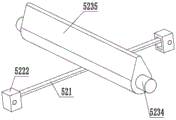
Fig. 5 is a schematic diagram of an extrusion column and a connection structure thereof in a dust removing device for desulfurization flue gas according to an embodiment of the present invention.
Wherein: the box body 1, the air inlet pipe 2, the air outlet pipe 3, the filter plate 4, the dust removing mechanism 5, the spray assembly 51, the fixed cylinder 511, the spray pipe 512, the guide pipe 513, the water inlet 514, the first rotating rod 515, the rotating disc 516, the push-pull rod 517, the sealing plate 518, the impurity removing assembly 52, the cleaning plate 521, the brush 5211, the translation part 522, the threaded rod 5221, the control block 5222, the hole dredging part 523, the chute 5231, the limit rod 5232, the return spring 5233, the second rotating rod 5234, the extrusion column 5235, the unidirectional flow guiding part 6, the first baffle 61, the fixed plate 62, the extrusion spring 63, the second baffle 64, the limit block 65, the driving assembly 7, the control box 71, the transmission fluted disc 72, the transmission belt 73 and the motor 74.
Description of the embodiments
It should be noted that, without conflict, the embodiments of the present invention and features of the embodiments may be combined with each other.
Specific implementations of the invention are described in detail below in connection with specific embodiments.
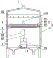
As shown in fig. 1 and fig. 4, the structure diagram of the dust removing device for desulfurization flue gas provided by the embodiment of the invention comprises a box body 1, wherein an air inlet pipe 2 is arranged on the side wall of the box body 1, an air outlet pipe 3 is arranged on the top wall of the box body 1, a filter plate 4 is fixedly arranged between the inner walls of the box body 1, meshes which are uniformly distributed are arranged on the surface of the filter plate 4, impurity discharging grooves are formed on two sides of the filter plate 4, a dust removing mechanism 5 which is mutually matched with the filter plate 4 is arranged in the inner cavity of the box body 1, the dust removing mechanism 5 comprises a spraying component 51 and an impurity removing component 52, the spraying component 51 is positioned in the inner cavity of the box body 1, the spraying component 51 is used for atomizing and humidifying the inner cavity of the box body 1, the impurity removing component 52 comprises a cleaning plate 521, a translation part 522 and a drain hole part 523, the cleaning plate 521 is positioned above the filter plate 4, the bottom wall of the cleaning plate 521 is provided with a brush 5211 which is mutually matched with the filter plate 4, the translation part 522 is positioned between two opposite side walls of the box body 1 and is connected with the filter plate 521, the translation part 522 is used for controlling the cleaning plate 521 to be mutually matched with the horizontal surface of the filter plate 521, and the horizontal movement part 523 is mutually translated along the direction of the cleaning component 523 and the horizontal movement direction of the cleaning component 523 is commonly used for driving the cleaning component 523 and the horizontal movement of the cleaning component 523 and the drain hole 521 is mutually along the direction, and the direction of the cleaning component 523 is commonly used for driving the cleaning component 523 and the horizontal movement, and 523 is, and the movement, and the 3, and the movement direction is, and the lower part is used.
When the dust removing device is used, an appropriate amount of alkaline solution is injected into the bottom of the box body 1, flue gas to be treated is conveyed into the box body 1 through the air inlet pipe 2, the alkaline solution at the bottom of the box body 1 is atomized and uniformly sprayed into the box body 1 by the spraying assembly 51, the atomized solution is attached to the mesh surface of the filter plate 4, the flue gas is fully contacted with the alkaline solution, the flue gas can be subjected to efficient sulfur removal treatment, the filter plate 4 and the spraying assembly 51 can synchronously filter dust impurities in the flue gas while the flue gas is subjected to sulfur removal treatment, the treated flue gas is discharged to the outer side of the box body 1 through the air outlet pipe 3, sulfate and dust generated by the flue gas treatment are attached to the surface of the filter plate 4 and the mesh position inside the filter plate 4, the translation part 522 can control the cleaning plate 521 to reciprocate along the surface of the filter plate 4, the brush 5211 on the surface of the cleaning plate 521 can effectively clean sulfate and dust attached to the surface of the filter plate 4, the sulfate impurities and the dust can be discharged to the bottom of the box body 1 through the impurity removing groove, the cleaning plate 521 can be pushed to reciprocate in the direction of the filter plate 521, the filter plate 521 can be continuously moved in the reciprocating direction of the mesh position of the filter plate 521, and the filter plate can be continuously cleaned in the reciprocating direction of the filter plate 521 along the mesh position of the filter plate 521.
As shown in fig. 1, 3 and 4, as a preferred embodiment of the present invention, the spray assembly 51 includes a fixed cylinder 511 fixedly installed at the bottom wall in the box 1, an opening is provided at the top of the fixed cylinder 511, a sealing plate 518 is slidably installed between the inner walls of the fixed cylinder 511, a spray pipe 512 located above the filter plate 4 is fixedly installed at the inner wall of the box 1, a conduit 513 is connected to the side wall of the fixed cylinder 511, one end of the conduit 513 far away from the fixed cylinder 511 is communicated with the spray pipe 512, a water inlet 514 is provided at the bottom end of the side wall of the fixed cylinder 511, a unidirectional flow guide 6 is provided in the fixed cylinder 511 and is matched with the conduit 513 and the water inlet 514, the unidirectional flow guide 6 is used for controlling the flow direction of the solution in the fixed cylinder 511, a first rotating rod 515 is rotatably installed at the end of the first rotating rod 515, a rotating disc 516 located right above the fixed cylinder 511 is rotatably connected to the side wall of the rotating disc 516 through a rotating shaft, one end of the eccentric rod 517 far away from the rotating disc 516 extends into the fixed cylinder 511 and is connected to the sealing plate 7 in a driving manner.
When in use, the driving assembly 7 drives the first rotating rod 515 to rotate so as to drive the rotating disc 516 to rotate, the rotating disc 516 and the push-pull rod 517 are mutually matched to control the sealing plate 518 to reciprocate up and down in the fixed cylinder 511, when the sealing plate 518 moves upwards in the fixed cylinder 511, the unidirectional flow guide part 6 and the water inlet 514 are mutually matched to control alkaline solution at the bottom in the box body 1 to flow into the fixed cylinder 511 through the water inlet 514, and when the sealing plate 518 moves downwards in the fixed cylinder 511, the unidirectional flow guide part 6 and the sealing plate 518 are mutually matched to push the solution in the fixed cylinder 511 to be conveyed into the guide pipe 513 and then into the spraying pipe 512, and the alkaline solution can be uniformly atomized and sprayed into the inner cavity of the box body 1 through the spraying pipe 512 to treat flue gas.
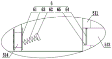
As shown in fig. 3, as a preferred embodiment of the present invention, the unidirectional flow guiding portion 6 includes a first baffle 61 rotatably mounted on the inner wall of the fixed cylinder 511 and attached to the water inlet 514, a fixed plate 62 is fixedly mounted between the inner walls of the fixed cylinder 511, a pressing spring 63 connected to the first baffle 61 is fixedly mounted on the side wall of the fixed plate 62, a second baffle 64 rotatably mounted on the inner wall of the conduit 513 and attached to the inner wall of the conduit 513, and a limiting block 65 cooperating with the second baffle 64 is fixedly mounted on the inner wall of the conduit 513.
By the cooperation of the pressing spring 63 and the limiting block 65, when the sealing plate 518 reciprocates in the fixed cylinder 511, the first baffle 61 and the second baffle 64 can be controlled to be respectively opened, and the alkaline solution in the box 1 can be controlled to flow into the fixed cylinder 511 and then flow into the guide pipe 513.
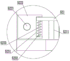
As shown in fig. 1, 2 and 4, as a preferred embodiment of the present invention, the translating portion 522 includes two sets of threaded rods 5221 that are oppositely distributed and mounted on opposite side walls of the case 1 in a co-rotating manner, the threaded rods 5221 are located above the filter plates 4, a control block 5222 is screwed on a surface of the threaded rods 5221, the control block 5222 is slidably connected to an inner wall of the case 1, two sets of oppositely distributed control blocks 5222 are respectively connected to two ends of the cleaning plate 521, and the threaded rods 5221 are connected to the driving assembly 7.
When in use, the driving assembly 7 controls the threaded rod 5221 to rotate, the threaded rod 5221 drives the control block 5222 to move along the axial direction of the threaded rod 5221 so as to drive the cleaning plate 521 to synchronously move, and the brush 5211 on the bottom wall of the cleaning plate 521 can efficiently clean impurities on the surface of the filter plate 4 while moving.
As shown in fig. 1, 2, 4 and 5, as a preferred embodiment of the present invention, the hole-opening portion 523 includes two sets of sliding grooves 5231 formed on two opposite side walls of the control block 5222, a limiting rod 5232 is fixedly installed in the sliding grooves 5231, two ends of the cleaning plate 521 extend into the sliding grooves 5231 and are slidably connected with the limiting rod 5232, a return spring 5233 surrounding the limiting rod 5232 and connected with the cleaning plate 521 is fixedly installed in the sliding grooves 5231, two opposite side walls of the box 1 are rotatably installed with a second rotating rod 5234, a pressing post 5235 matched with the cleaning plate 521 is fixedly installed on a surface of the second rotating rod 5234, a cross section of the pressing post 5235 is of an eccentric wheel structure, and the second rotating rod 5234 is connected with the driving assembly 7.
When in use, the driving assembly 7 drives the second rotating rod 5234 to rotate so as to drive the extrusion column 5235 to rotate, the extrusion column 5235 and the reset spring 5233 mutually cooperate to control the cleaning plate 521 to move in the vertical direction while horizontally moving, the extrusion column 5235 pushes the cleaning plate 521 to move downwards so as to control the brush 5211 to be inserted into the mesh on the surface of the filter plate 4 for dredging and removing impurities, and the reset spring 5233 and the chute 5231 mutually cooperate to push the cleaning plate 521 to move upwards and restore to the original position.
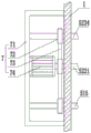
As shown in fig. 4, as a preferred embodiment of the present invention, the driving assembly 7 includes a control box 71 fixedly mounted on a side wall of the box 1, the first rotating rod 515, the second rotating rod 5234 and one end of the threaded rod 5221 extend into the control box 71 respectively and are fixedly connected with a transmission fluted disc 72, a plurality of groups of the transmission fluted discs 72 are commonly connected with a transmission belt 73, a motor 74 is fixedly mounted in the control box 71, and an output shaft of the motor 74 is fixedly connected with the threaded rod 5221.
When in use, the starting motor 74 drives one set of threaded rods 5221 to rotate so as to drive the transmission fluted disc 72 to rotate, the transmission fluted disc 72 and the transmission belt 73 are mutually matched to drive a plurality of sets of transmission fluted discs 72 to synchronously rotate, and the transmission fluted discs 72 respectively drive the first rotating rod 515, the second rotating rod 5234 and the threaded rods 5221 to rotate in the inner cavity of the box body 1.
As shown in fig. 1, as a preferred embodiment of the present invention, the bottom wall of the case 1 is provided in a funnel-shaped structure. And the sulfate and dust generated by the flue gas treatment are precipitated to the inner bottom of the box body 1, and after impurities are precipitated to a certain degree, the impurities are discharged through a trash discharging pipe at the bottom of the box body 1.
The working principle of the invention is as follows: when the device is used, an appropriate amount of alkaline solution is injected into the bottom of the box body 1, smoke to be treated is conveyed into the box body 1 through the air inlet pipe 2, the starting motor 74 drives the set of threaded rods 5221 to rotate so as to drive the transmission fluted disc 72 to rotate, the transmission fluted disc 72 and the transmission belt 73 are mutually matched to drive the plurality of sets of transmission fluted discs 72 to synchronously rotate, the plurality of sets of transmission fluted discs 72 respectively drive the first rotating rod 515, the second rotating rod 5234 and the threaded rods 5221 to rotate in the inner cavity of the box body 1, the rotating disc 516 and the push-pull rod 517 are mutually matched to control the sealing plate 518 to reciprocate up and down in the fixed cylinder 511, when the sealing plate 518 moves upwards in the fixed cylinder 511, the one-way flow guide part 6 and the water inlet 514 are mutually matched to control the alkaline solution at the bottom of the box body 1 to flow into the fixed cylinder 511 through the water inlet 514, and when the one-way flow guide part 6 and the sealing plate 518 move downwards in the fixed cylinder 511, the one-way flow guide part 6 and the sealing plate 518 are mutually matched to push the solution in the fixed cylinder 511 to the guide pipe 513 to move up and then to the spraying pipe 512, the alkaline solution 518 is mutually matched to control the rotating plate 516, and the sealing plate 518 to reciprocate in the fixed cylinder 518, the sealing plate 518 in the fixed cylinder, and the sealing plate 518 is moved up and the sealing plate, and the sealing plate 518 is mutually, and the sealing plate 518 is moved in the mode, and the up and the upward, and the smoke can be uniformly sprayed in the smoke to the bottom and the smoke to be uniformly sprayed and atomized through the box 1. The threaded rod 5221 drives the control block 5222 to move along the axis direction of the threaded rod 5221 and then drives the cleaning plate 521 to synchronously move, the brush 5211 at the bottom wall of the cleaning plate 521 can efficiently clean impurities on the surface of the filter plate 4 while moving, the second rotating rod 5234 rotates and then drives the extrusion column 5235 to rotate, the extrusion column 5235 and the reset spring 5233 mutually cooperate to control the cleaning plate 521 to move in the vertical direction while horizontally moving, the extrusion column 5235 pushes the cleaning plate 521 to move downwards and then control the brush 5211 to be inserted into meshes on the surface of the filter plate 4 to dredge and remove impurities, and the reset spring 5233 and the sliding groove 5231 mutually cooperate to push the cleaning plate 521 to move upwards and restore to the original position.
While the preferred embodiments of the present invention have been described in detail, the present invention is not limited to the above embodiments, and various changes can be made without departing from the spirit of the present invention within the knowledge of those skilled in the art.
Claims (5)
1. The dust removing device for the desulfurized flue gas comprises a box body, an air inlet pipe is arranged on the side wall of the box body, an exhaust pipe is arranged on the top wall of the box body, and the dust removing device is characterized in that a filter plate is fixedly arranged between the inner walls of the box body, meshes which are uniformly distributed are arranged on the surface of the filter plate, a dust removing mechanism which is mutually matched with the filter plate is arranged in the inner cavity of the box body, the dust removing mechanism comprises a spraying component and a impurity removing component, the spraying component is positioned in the inner cavity of the box body, the spraying component is used for atomizing and humidifying the inner cavity of the box body, the impurity removing component comprises a cleaning plate, a translation part and a hole dredging part, the cleaning plate is positioned above the filter plate, a brush which is mutually matched with the filter plate is arranged on the bottom wall of the cleaning plate, the translation part is positioned between two opposite side walls of the box body and is connected with the cleaning plate, the translation part is used for controlling the cleaning plate to reciprocate along the horizontal direction on the surface of the filter plate, the translation part comprises two groups of oppositely distributed threaded rods which are arranged on two opposite side walls of the box body in a common rotation way, the threaded rods are positioned above the filter plate, the surface of the threaded rods is in threaded connection with a control block, the control block is in sliding connection with the inner wall of the box body, the two groups of oppositely distributed control blocks are respectively connected with two ends of the cleaning plate, the threaded rods are connected with a driving assembly, the hole dredging part is positioned in the inner cavity of the box body and is mutually matched with the cleaning plate, the hole dredging part is used for controlling the cleaning plate to reciprocate along the vertical direction, the hole dredging part comprises two groups of sliding grooves which are respectively arranged on two opposite side walls of the control block, a limiting rod is fixedly arranged in the sliding grooves, two ends of the cleaning plate respectively extend into the sliding grooves and are in sliding connection with the limiting rod, the utility model discloses a cleaning device, including the cleaning board, the spout, including the spout, the spout is internal, fixed mounting has the reset spring who encircles the gag lever post and be connected with the cleaning board, the second dwang is installed in the relative both sides wall joint rotation of box, second dwang surface fixed mounting has the extrusion post of mutually supporting with the cleaning board, the extrusion post cross section is eccentric wheel structure, the second dwang is connected with drive assembly, spray assembly, translation portion and dredge the hole portion joint connection and have drive assembly, drive assembly is used for controlling spray assembly, translation portion and dredge hole portion.
2. The dust collector for desulfurization flue gas of claim 1, wherein the spray assembly comprises a fixed cylinder fixedly installed on the bottom wall in the box body, an opening is formed in the top of the fixed cylinder, a sealing plate is slidably installed between the inner walls of the fixed cylinder, a spray pipe located above the filter plate is fixedly installed on the inner walls of the box body, a guide pipe is connected to the side wall of the fixed cylinder, one end of the guide pipe, far away from the fixed cylinder, is communicated with the spray pipe, a water inlet is formed in the bottom end of the side wall of the fixed cylinder, a one-way flow guide part matched with the guide pipe and the water inlet is arranged in the fixed cylinder, the one-way flow guide part is used for controlling the flowing direction of solution in the fixed cylinder, a first rotating rod is rotatably installed on the inner wall of the box body, a rotating disc located right above the fixed cylinder is fixedly installed at the end of the first rotating rod, a rod is rotatably connected to the eccentric position of the side wall of the rotating disc through a rotating shaft, one end of the rod, far away from the rotating disc, extends into the fixed cylinder and is rotatably connected with the sealing plate, and the first rotating rod is connected with the driving assembly.
3. The dust collector for desulfurization flue gas of claim 2, wherein the unidirectional flow guiding portion comprises a first baffle plate which is rotatably installed on the inner wall of the fixed cylinder and is attached to the water inlet, a fixed plate is fixedly installed between the inner walls of the fixed cylinder, an extrusion spring connected with the first baffle plate is fixedly installed on the side wall of the fixed plate, a second baffle plate attached to the inner wall of the conduit is rotatably installed on the inner wall of the conduit, and a limiting block which is mutually matched with the second baffle plate is fixedly installed on the inner wall of the conduit.
4. The dust collector for desulfurization flue gas of claim 2, wherein the driving assembly comprises a control box fixedly mounted on a side wall of the box body, the first rotating rod, the second rotating rod and one end of the threaded rod extend into the control box respectively and are fixedly connected with a transmission fluted disc, a plurality of groups of transmission fluted discs are connected with a transmission belt together, a motor is fixedly mounted in the control box, and an output shaft of the motor is fixedly connected with the threaded rod.
5. The dust collector for desulfurization flue gas of claim 1, wherein the bottom wall of the case is provided in a funnel-like structure.
Priority Applications (1)
| Application Number | Priority Date | Filing Date | Title |
|---|---|---|---|
| CN202310083373.9A CN115779594B (en) | 2023-02-08 | 2023-02-08 | Dust collector for desulfurization flue gas |
Applications Claiming Priority (1)
| Application Number | Priority Date | Filing Date | Title |
|---|---|---|---|
| CN202310083373.9A CN115779594B (en) | 2023-02-08 | 2023-02-08 | Dust collector for desulfurization flue gas |
Publications (2)
| Publication Number | Publication Date |
|---|---|
| CN115779594A CN115779594A (en) | 2023-03-14 |
| CN115779594B true CN115779594B (en) | 2023-04-25 |
Family
ID=85430531
Family Applications (1)
| Application Number | Title | Priority Date | Filing Date |
|---|---|---|---|
| CN202310083373.9A Active CN115779594B (en) | 2023-02-08 | 2023-02-08 | Dust collector for desulfurization flue gas |
Country Status (1)
| Country | Link |
|---|---|
| CN (1) | CN115779594B (en) |
Families Citing this family (2)
| Publication number | Priority date | Publication date | Assignee | Title |
|---|---|---|---|---|
| CN116808658A (en) * | 2023-04-12 | 2023-09-29 | 连云港赣榆华瑞机械设备有限公司 | Filter equipment is used in bean curd preparation |
| CN116617782A (en) * | 2023-06-09 | 2023-08-22 | 西安交通大学医学院第一附属医院 | An operating room anesthesia waste gas treatment device |
Family Cites Families (7)
| Publication number | Priority date | Publication date | Assignee | Title |
|---|---|---|---|---|
| CN209204994U (en) * | 2018-11-27 | 2019-08-06 | 温州市三合环保设备有限公司 | A kind of waste gas treatment equipment of recyclable waste heat |
| CN210385292U (en) * | 2019-06-27 | 2020-04-24 | 马玉英 | Device for purifying oil fume and dust |
| CN211025802U (en) * | 2019-11-04 | 2020-07-17 | 晋江市鹏祥环保设备有限公司 | An energy-saving desulfurization spray tower |
| CN212119222U (en) * | 2020-03-11 | 2020-12-11 | 汉中德诚冶金技术有限公司 | Metallurgical waste water filter equipment |
| CN217092878U (en) * | 2022-04-06 | 2022-08-02 | 兴嵘环境科技(上海)有限公司 | Processing apparatus of unorganized organic waste gas |
| CN115253643B (en) * | 2022-08-24 | 2025-06-17 | 上海泰欣环境工程有限公司 | Steel sintering flue gas desulfurization and denitrification treatment system |
| CN218452008U (en) * | 2022-10-20 | 2023-02-07 | 江苏省交通工程集团有限公司 | Windproof dust suppression net convenient to clean |
-
2023
- 2023-02-08 CN CN202310083373.9A patent/CN115779594B/en active Active
Also Published As
| Publication number | Publication date |
|---|---|
| CN115779594A (en) | 2023-03-14 |
Similar Documents
| Publication | Publication Date | Title |
|---|---|---|
| CN115779594B (en) | Dust collector for desulfurization flue gas | |
| WO2023131160A1 (en) | Intelligent coal dust purification system for power plant power generation | |
| CN218011792U (en) | A device for absorbing and treating waste gas from atmospheric pollution | |
| CN217473062U (en) | A flue gas desulfurization, denitrification and dust removal device | |
| CN118874162A (en) | A fume filtration device for drying furnace used in the production and processing of quartz sand | |
| CN212309084U (en) | Renewable particulate matter filtering component | |
| CN2505710Y (en) | Double-tube cyclone wet flue gas cleaner | |
| CN223324316U (en) | New plaster waste gas purification tower | |
| CN223439548U (en) | A desulfurization and purification system for tail gas from refractory brick production | |
| CN222384539U (en) | Tower wall anti-caking device for spray reaction tower | |
| CN221333396U (en) | Pollution emission reduction filter equipment | |
| CN220939787U (en) | Atmospheric pollution treatment dust collector | |
| CN120305769B (en) | A flue gas denitrification SCR pre-filter device | |
| CN219128763U (en) | a spraying device | |
| CN223337060U (en) | Dust treatment device for phosphogypsum processing | |
| CN223861569U (en) | Converter steelmaking dust removal spray set capable of fully contacting reaction | |
| CN111603930A (en) | Clean briquette burning boiler | |
| CN214020046U (en) | Wet desulphurization dust remover | |
| CN223430158U (en) | Wet electrostatic dust removal desulfurization and denitrification equipment | |
| CN214120094U (en) | Desulfurization and denitrification chimney | |
| CN221752872U (en) | A desulfurization device for air pollution control | |
| CN220478476U (en) | Waste gas purification environmental protection equipment | |
| CN219580140U (en) | Sulfur dioxide waste gas smoke and dust remove device | |
| CN221491950U (en) | Smoke purifying equipment for garbage power generation | |
| CN219441251U (en) | Flue gas desulfurization absorption circulation device |
Legal Events
| Date | Code | Title | Description |
|---|---|---|---|
| PB01 | Publication | ||
| PB01 | Publication | ||
| SE01 | Entry into force of request for substantive examination | ||
| SE01 | Entry into force of request for substantive examination | ||
| GR01 | Patent grant | ||
| GR01 | Patent grant |