CN115750411A - Ceiling fan based on axial flux motor - Google Patents

Ceiling fan based on axial flux motor Download PDF

Info

Publication number
CN115750411A
CN115750411A CN202211338795.8A CN202211338795A CN115750411A CN 115750411 A CN115750411 A CN 115750411A CN 202211338795 A CN202211338795 A CN 202211338795A CN 115750411 A CN115750411 A CN 115750411A
Authority
CN
China
Prior art keywords
stator
fan blade
rotor
assembly
hole
Prior art date
Legal status (The legal status is an assumption and is not a legal conclusion. Google has not performed a legal analysis and makes no representation as to the accuracy of the status listed.)
Pending
Application number
CN202211338795.8A
Other languages
Chinese (zh)
Inventor
卢伟钿
Current Assignee (The listed assignees may be inaccurate. Google has not performed a legal analysis and makes no representation or warranty as to the accuracy of the list.)
Zhiqin Photoelectric Technology Zhongshan Co ltd
Original Assignee
Zhiqin Photoelectric Technology Zhongshan Co ltd
Priority date (The priority date is an assumption and is not a legal conclusion. Google has not performed a legal analysis and makes no representation as to the accuracy of the date listed.)
Filing date
Publication date
Application filed by Zhiqin Photoelectric Technology Zhongshan Co ltd filed Critical Zhiqin Photoelectric Technology Zhongshan Co ltd
Publication of CN115750411A publication Critical patent/CN115750411A/en
Priority to US18/297,082 priority Critical patent/US12149152B2/en
Pending legal-status Critical Current

Links

Images

Landscapes

  • Structures Of Non-Positive Displacement Pumps (AREA)

Abstract

The invention discloses a ceiling fan based on an axial flux motor, which adopts the axial flux motor to drive fan blades to rotate and has the characteristics of high rotating efficiency, stable operation, relatively small volume as a whole, safety and reliability; the fan blade connecting piece connecting part is fixedly connected with the rotor assembly relatively, the fan blade connecting piece inserting part extends into the fan blade and is fixedly connected with the fan blade relatively, the problem that the fan blade is damaged easily due to the fact that the fan blade connecting piece is directly connected with the surface of the fan blade in the prior art can be avoided, meanwhile, the fan blade connecting piece can also improve the structural strength of the fan blade, and the probability of deformation of the fan blade is reduced.

Description

一种基于轴向磁通电机的吊扇A Ceiling Fan Based on Axial Flux Motor

【技术领域】【Technical field】

本发明涉及一种基于轴向磁通电机的吊扇。The present invention relates to a ceiling fan based on an axial flux motor.

【背景技术】【Background technique】

工业吊扇是一款广泛应用于工业厂房、物流仓储、候车室、展览馆、体育馆、商超等高大空间,作为空间通风,人员降温的一种常见工业用机器。Industrial ceiling fan is a common industrial machine widely used in high and large spaces such as industrial plants, logistics storage, waiting rooms, exhibition halls, gymnasiums, supermarkets, etc., as a space ventilation and personnel cooling.

工业吊扇可以推射大量气流到地面,在地面形成一定高度的气流层水平运动,从而促成了整体空气循环,这样的好处在于全方位的地面覆盖和空气的立体循环,可以做到自然通风、超大覆盖面积。The industrial ceiling fan can push a large amount of airflow to the ground, forming a horizontal movement of the airflow layer at a certain height on the ground, thus promoting the overall air circulation. Coverage area.

然而,工业吊扇存在如下缺陷:However, industrial ceiling fans have the following defects:

1、现阶段工业吊扇的扇叶与电机之间通常采用叶叉连接,叶叉一端与电机固定连接,所述叶叉另一端相对固定连接于扇叶表面上。如今为了降低扇叶生产制造成本和减轻扇叶重量,扇叶通常设计得比较薄,致使叶叉与扇叶表面连接则容易对扇叶造成损伤,影响扇叶使用寿命,增加了扇叶修为更换成本;另外扇叶较薄还致使扇叶刚性较低,则扇叶在转动过程中容易晃动而引起叶叉与扇叶之间连接疲劳,存在不安全因素。1. At present, the fan blade of the industrial ceiling fan is usually connected with the motor by a leaf fork, one end of the leaf fork is fixedly connected to the motor, and the other end of the leaf fork is relatively fixedly connected to the surface of the fan blade. Nowadays, in order to reduce the manufacturing cost of the fan blade and reduce the weight of the fan blade, the fan blade is usually designed to be relatively thin, so that the connection between the blade fork and the surface of the fan blade will easily cause damage to the fan blade, affect the service life of the fan blade, and increase the maintenance of the fan blade. Replacement cost; in addition, the thinner fan blade also leads to lower rigidity of the fan blade, and the fan blade is easy to shake during rotation, which causes fatigue in the connection between the blade fork and the fan blade, and there is an unsafe factor.

2、现阶段应用于工业吊扇的电机中定子组件通常包括定子环、呈圆周方向间隔均匀分布在定子环上的若干个定子绕线柱,每一定子绕线柱端部设有挡线部;然而,上述定子组件受结构设计限制,采用绕线设备进行绕线时,为了避免干涉,通常需要在相邻两定子绕线柱之间的定子容纳槽内进行预留避让空间,则在定子组件大小一定的情况下,上述定子组件绕线的圈数则较少,影响磁通量的大小,进而影响电机的输出功率及扭矩,从而影响工业吊扇的使用效果。如果需要保证绕线的圈数,则要加大设计定子组件,而该方式又将导致轴向磁通电机整体体积及重量变大,同时也增加制造成本。2. The stator assembly used in the motor of industrial ceiling fans at the present stage usually includes a stator ring, a number of stator winding posts evenly distributed on the stator ring in the circumferential direction, and each stator winding post is provided with a retaining part at the end; However, the above-mentioned stator assembly is limited by the structural design. When using winding equipment for winding, in order to avoid interference, it is usually necessary to reserve space in the stator accommodation slot between two adjacent stator winding posts. Then, in the stator assembly In the case of a certain size, the number of winding turns of the above-mentioned stator assembly is less, which affects the size of the magnetic flux, which in turn affects the output power and torque of the motor, thereby affecting the use effect of the industrial ceiling fan. If it is necessary to ensure the number of turns of the winding, the design of the stator assembly must be increased, and this method will lead to an increase in the overall volume and weight of the axial flux motor, and will also increase the manufacturing cost.

3、现阶段应用于工业吊扇的电机中定子组件与定子轴通常采用卡环等连接结构连接固定,然而,由于卡环长时间支撑定子组件,容易造成卡环出现松动、形变等现象,影响定子组件与定子轴固定连接,致使定子组件与定子轴之间存在结构不稳定和不安全的问题,影响工业吊扇的正常使用。3. At the present stage, the stator assembly and the stator shaft of the motor used in industrial ceiling fans are usually connected and fixed by a connection structure such as a snap ring. However, because the snap ring supports the stator assembly for a long time, it is easy to cause loosening and deformation of the snap ring, which affects the stator. The component is fixedly connected to the stator shaft, which causes structural instability and insecurity between the stator component and the stator shaft, which affects the normal use of the industrial ceiling fan.

4、现阶段应用于工业吊扇的电机中转子组件通常采用滚珠轴承与定子轴转动连接,由于转子组件受自身重力和扇叶重力影响会产生一个沿轴向向下作用力,即转子组件使得滚珠轴承受一个沿轴向向下作用力而造成滚珠轴承的运行困难,进而导致转子组件相对定子轴运行不平稳、不顺畅的问题,导致工业吊扇运行效果差和运行不平稳。4. At present, the rotor assembly of the motor used in industrial ceiling fans is usually connected to the stator shaft by ball bearings. Because the rotor assembly is affected by its own gravity and the gravity of the fan blade, it will generate a downward force in the axial direction, that is, the rotor assembly makes the ball The bearing is subjected to a downward force in the axial direction, which makes the operation of the ball bearing difficult, which in turn causes the rotor assembly to run unsmoothly and unsmoothly relative to the stator shaft, resulting in poor and unsmooth operation of the industrial ceiling fan.

为此,本发明即针对上述问题而研究提出。For this reason, the present invention promptly researches and proposes at the above-mentioned problem.

【发明内容】【Content of invention】

本发明目的是克服了现有技术的不足,提供一种基于轴向磁通电机的吊扇,可以改善现有技术存在的问题,具有结构稳定,结构强度高,运行平稳,安全可靠的特点。The purpose of the present invention is to overcome the deficiencies of the prior art, and provide a ceiling fan based on an axial flux motor, which can improve the existing problems of the prior art, and has the characteristics of stable structure, high structural strength, stable operation, safety and reliability.

本发明是通过以下技术方案实现的:The present invention is achieved through the following technical solutions:

一种基于轴向磁通电机的吊扇,包括定子轴1、相对固定地连接在定子轴1上的定子组件2、位于定子组件2上方且可相对定子轴1转动的转子组件3和呈圆周分布于转子组件3上的若干片扇叶5,每一所述扇叶5通过扇叶连接件4与转子组件3连接,所述扇叶连接件4具有连接部和插接部,所述扇叶连接件4连接部与转子组件3相对固定连接,所述扇叶连接件4插接部伸入扇叶5内而与扇叶5相对固定连接。A ceiling fan based on an axial flux motor, comprising a stator shaft 1, a stator assembly 2 relatively fixedly connected to the stator shaft 1, a rotor assembly 3 located above the stator assembly 2 and rotatable relative to the stator shaft 1, and circumferentially distributed A plurality of fan blades 5 on the rotor assembly 3, each of the fan blades 5 is connected to the rotor assembly 3 through a fan blade connector 4, and the fan blade connector 4 has a connecting part and a socket part, and the fan blade The connecting part of the connecting part 4 is relatively fixedly connected with the rotor assembly 3 , and the insertion part of the fan blade connecting part 4 protrudes into the fan blade 5 and is relatively fixedly connected with the fan blade 5 .

如上所述一种基于轴向磁通电机的吊扇,所述定子组件2包括呈圆环状的定子环22和线圈绕组23,所述定子环22在圆周方向上均匀分布有沿轴向延伸的定子绕线柱221,所述定子环22上且位于相邻两所述定子绕线柱221之间形成有定子容纳槽222,所述定子容纳槽222沿径向方向的两端呈开口设置,所述定子容纳槽222相对两侧面为直面,所述线圈绕组23包括线圈本体231和设在线圈本体231中部上用于与定子绕线柱221配合连接的线圈通孔232。As mentioned above, a ceiling fan based on an axial flux motor, the stator assembly 2 includes an annular stator ring 22 and a coil winding 23, and the stator ring 22 is evenly distributed in the circumferential direction with axially extending A stator winding post 221, a stator receiving groove 222 is formed on the stator ring 22 and between two adjacent stator winding posts 221, and the two ends of the stator receiving groove 222 along the radial direction are open. The opposite sides of the stator accommodating slot 222 are straight faces, and the coil winding 23 includes a coil body 231 and a coil through hole 232 provided in the middle of the coil body 231 for mating connection with the stator winding post 221 .

如上所述一种基于轴向磁通电机的吊扇,所述定子绕线柱221具有内圆侧壁2211、第一直面侧壁2212、外圆侧壁2213和第二直面侧壁2214,每一个所述定子容纳槽222位于相邻两所述定子绕线柱221之间且由一所述定子绕线柱221的第一直面侧壁2212与另一所述定子绕线柱221的第二直面侧壁2214形成。As mentioned above, a ceiling fan based on an axial flux motor, the stator winding post 221 has an inner circular side wall 2211, a first straight side wall 2212, an outer circular side wall 2213 and a second straight side wall 2214, each One of the stator receiving slots 222 is located between two adjacent stator winding posts 221 and is composed of the first straight side wall 2212 of one stator winding post 221 and the first straight side wall 2212 of the other stator winding post 221. Two straight facing sidewalls 2214 are formed.

如上所述一种基于轴向磁通电机的吊扇,所述定子绕线柱221的中心线2215经过所述定子环22的圆心,且每一个所述定子绕线柱221的第一直面侧壁2212和第二直面侧壁2214向定子环22圆心延伸而相交于一平行于所述定子环22中心轴线的直线。As mentioned above, a ceiling fan based on an axial flux motor, the center line 2215 of the stator winding post 221 passes through the center of the stator ring 22, and the first straight side of each stator winding post 221 The wall 2212 and the second straight side wall 2214 extend toward the center of the stator ring 22 and intersect a straight line parallel to the central axis of the stator ring 22 .

如上所述一种基于轴向磁通电机的吊扇,所述定子组件2还包括与定子环22相适配而连接的定子底壳21,所述定子环22底部直接或间接抵触于定子底壳21内底而进行热传导。According to the above-mentioned ceiling fan based on an axial flux motor, the stator assembly 2 further includes a stator bottom case 21 adapted and connected with a stator ring 22, and the bottom of the stator ring 22 directly or indirectly interferes with the stator bottom case 21 inner bottom for heat conduction.

如上所述一种基于轴向磁通电机的吊扇,所述定子组件2包括定子底壳21和与定子底壳21连接的定子环22,所述定子底壳21底壁上设有用于与定子轴1配合连接的底壳通孔211,所述定子轴1下端部具有与其一体成型的定子轴肩11,且当所述定子组件2通过底壳通孔211与定子轴1连接时,所述定子轴肩11的内侧面抵靠于底壳通孔211外侧面以防止定子组件2相对定子轴1沿轴向向下窜动。As mentioned above, a ceiling fan based on an axial flux motor, the stator assembly 2 includes a stator bottom case 21 and a stator ring 22 connected to the stator bottom case 21, and the bottom wall of the stator bottom case 21 is provided with a Bottom case through hole 211 matingly connected with shaft 1, the lower end of stator shaft 1 has a stator shoulder 11 integrally formed with it, and when the stator assembly 2 is connected to stator shaft 1 through bottom case through hole 211, the The inner surface of the stator shoulder 11 abuts against the outer surface of the through hole 211 of the bottom case to prevent the stator assembly 2 from axially moving downward relative to the stator shaft 1 .

如上所述一种基于轴向磁通电机的吊扇,所述转子组件3包括位于定子组件2上方的转子盘31,所述转子盘31上设有与定子轴1配合的转子通孔311,所述转子盘31与定子轴1之间连接有转子转动件32,所述转子盘31与定子轴1之间或转子盘31与定子组件2之间设有用于支撑转子盘31相对定子轴1平稳转动的支撑转动组件33。As mentioned above, a ceiling fan based on an axial flux motor, the rotor assembly 3 includes a rotor disk 31 located above the stator assembly 2, and the rotor disk 31 is provided with a rotor through hole 311 matched with the stator shaft 1, so A rotor rotating member 32 is connected between the rotor disk 31 and the stator shaft 1, and a rotor disk 31 is provided between the rotor disk 31 and the stator shaft 1 or between the rotor disk 31 and the stator assembly 2 to support the rotor disk 31 to rotate smoothly relative to the stator shaft 1. The supporting rotating assembly 33.

如上所述一种基于轴向磁通电机的吊扇,所述转子转动件32为设在转子通孔311与定子轴1之间且向心力沿轴向向下的向下推力轴承,所述向下推力轴承内圈与定子轴1相对固定连接,所述向下推力轴承外圈与转子通孔311内壁相对固定连接。As mentioned above, a ceiling fan based on an axial flux motor, the rotor rotating part 32 is a downward thrust bearing arranged between the rotor through hole 311 and the stator shaft 1, and the centripetal force is axially downward. The inner ring of the thrust bearing is relatively fixedly connected to the stator shaft 1 , and the outer ring of the downward thrust bearing is relatively fixedly connected to the inner wall of the rotor through hole 311 .

如上所述一种基于轴向磁通电机的吊扇,所述支撑转动组件33包括设在转子盘31与定子组件2之间的平面轴承,所述平面轴承下支撑环与定子组件2相对固定连接,所述平面轴承上支撑环与转子盘31相对固定连接;或者所述支撑转动组件33包括设在转子盘31与定子轴1之间且向下力沿轴向向上的向上推力轴承,所述向上推力轴承内圈与定子轴1相对固定连接,所述向上推力轴承外圈与转子通孔311内壁相对固定连接。As mentioned above, a ceiling fan based on an axial flux motor, the supporting and rotating assembly 33 includes a plane bearing arranged between the rotor disk 31 and the stator assembly 2, and the support ring of the plane bearing is relatively fixedly connected with the stator assembly 2 , the support ring on the plane bearing is relatively fixedly connected to the rotor disk 31; or the support rotation assembly 33 includes an upward thrust bearing arranged between the rotor disk 31 and the stator shaft 1 and the downward force is axially upward, the The inner ring of the upward thrust bearing is relatively fixedly connected with the stator shaft 1 , and the outer ring of the upward thrust bearing is relatively fixedly connected with the inner wall of the rotor through hole 311 .

如上所述一种基于轴向磁通电机的吊扇,所述扇叶5呈中空设置,所述扇叶5上内壁与下内壁之间间隔地设有左连接内筋51和右连接内筋52,所述左连接内筋51和右连接内筋52上相向地设有左限位槽511和右限位槽521,所述左限位槽511与右限位槽521之间形成有供扇叶连接件4插接部插接定位的定位空间53;所述扇叶5上且相应位于定位空间53处设有扇叶安装孔531;所述扇叶连接件4上设有当扇叶连接件4插接部插接于定位空间53内时用于与扇叶安装孔531对齐以连接的连接件安装孔42,所述扇叶连接件4连接部上还设有用于与转子组件3连接配合的连接件连孔41;还包括能同时穿设于扇叶安装孔531和连接件安装孔42内以将扇叶连接件4与扇叶5固定连接的连接螺栓/铆钉。As mentioned above, a ceiling fan based on an axial flux motor, the fan blade 5 is hollow, and the left connecting inner rib 51 and the right connecting inner rib 52 are arranged at intervals between the upper inner wall and the lower inner wall of the fan blade 5 , the left connecting rib 51 and the right connecting inner rib 52 are oppositely provided with a left limiting groove 511 and a right limiting groove 521, and a supply fan is formed between the left limiting groove 511 and the right limiting groove 521 The positioning space 53 for inserting and positioning the plug-in part of the leaf connector 4; the fan blade 5 is provided with a fan blade installation hole 531 correspondingly located at the positioning space 53; The connector installation hole 42 is used to align with the fan blade installation hole 531 for connection when the socket part of the fan blade connector 4 is inserted into the positioning space 53. The mating connector connecting hole 41 also includes connecting bolts/rivets that can pass through the fan blade installation hole 531 and the connector installation hole 42 at the same time to securely connect the fan blade connector 4 and the fan blade 5 .

与现有技术相比较,本发明具有如下优点:Compared with the prior art, the present invention has the following advantages:

1、本发明相对现有技术中采用径向磁通电机来带动扇叶转动而言,本发明采用轴向磁通电机来带动扇叶转动,具有转动效率高,运行平稳,体积整体相对较小,安全可靠的特点。1. Compared with the radial flux motor used in the prior art to drive the fan blades to rotate, the present invention uses an axial flux motor to drive the fan blades to rotate, which has high rotation efficiency, stable operation, and a relatively small overall volume , safe and reliable features.

2本发明中所述扇叶连接件连接部与转子组件相对固定连接,所述扇叶连接件插接部伸入扇叶内而与扇叶相对固定连接,能够避免现有技术中扇叶连接件直接与扇叶表面连接而容易造成扇叶损伤的问题,同时扇叶连接件也能提高扇叶的结构强度,降低扇叶发生形变的概率。2. In the present invention, the connection part of the fan blade connector is relatively fixedly connected with the rotor assembly, and the insertion part of the fan blade connector protrudes into the fan blade and is relatively fixedly connected with the fan blade, which can avoid the fan blade connection in the prior art. The parts are directly connected to the surface of the fan blade, which may easily cause damage to the fan blade. At the same time, the fan blade connector can also improve the structural strength of the fan blade and reduce the probability of deformation of the fan blade.

3、所述定子组件包括呈圆环状的定子环和线圈绕组,所述定子环在圆周方向上均匀分布有沿轴向延伸的定子绕线柱,所述定子环上且位于相邻两所述定子绕线柱之间形成有定子容纳槽,所述定子容纳槽沿径向方向的两端呈开口设置,所述定子容纳槽相对两侧面为直面,所述线圈绕组包括线圈本体和设在线圈本体中部上用于与定子绕线柱配合连接的线圈通孔,能够使得装配在定子绕线柱上的线圈绕组与定子绕线柱贴合更加紧密,进而使得线圈绕组与定子绕线柱连接更加稳固,同时可高效地将线圈绕组与定子绕线柱进行装配,且在单位空间内最大化地确保了线圈绕组的圈数,以提高磁通量,进而改善轴向磁通电机的输出功率、扭矩,并确保轴向磁通电机整机体积最小化,有效降低生产制造成本。3. The stator assembly includes an annular stator ring and a coil winding. The stator ring is evenly distributed in the circumferential direction with axially extending stator winding posts. The stator ring is located on the two adjacent Stator accommodating slots are formed between the stator winding columns, the two ends of the stator accommodating slots in the radial direction are open, the opposite sides of the stator accommodating slots are straight faces, and the coil winding includes a coil body and a wire The coil through hole in the middle part of the coil body is used to connect with the stator winding post, which can make the coil winding assembled on the stator winding post fit more closely with the stator winding post, thereby making the coil winding and the stator winding post connected It is more stable, and at the same time, it can efficiently assemble the coil winding and the stator winding post, and maximize the number of turns of the coil winding in a unit space to increase the magnetic flux, thereby improving the output power and torque of the axial flux motor , and ensure that the volume of the axial flux motor is minimized, effectively reducing the manufacturing cost.

4、所述定子组件还包括与定子环相适配而连接的定子底壳,所述定子环底部直接或间接抵触于定子底壳内底而进行热传导,能够对定子组件起到保护作用,同时提高散热效率。4. The stator assembly also includes a stator bottom case that is adapted and connected to the stator ring. The bottom of the stator ring is directly or indirectly in contact with the inner bottom of the stator bottom case for heat conduction, which can protect the stator assembly. At the same time Improve cooling efficiency.

5、所述定子组件包括定子底壳和与定子底壳连接的定子环,所述定子底壳底壁上设有用于与定子轴配合连接的底壳通孔,所述定子轴下端部具有与其一体成型的定子轴肩,且当所述定子组件通过底壳通孔与定子轴连接时,所述定子轴肩的内侧面抵靠于底壳通孔外侧面以防止定子组件相对定子轴沿轴向向下窜动,能够使得定子组件与定子轴连接更加牢固可靠和结构更加稳定,另外定子轴肩与定子轴一体成型,具有结构简单,易于成型制造的特点。5. The stator assembly includes a stator bottom case and a stator ring connected to the stator bottom case. The bottom wall of the stator bottom case is provided with a bottom case through hole for matching with the stator shaft. The lower end of the stator shaft has a One-piece stator shoulder, and when the stator assembly is connected to the stator shaft through the through hole of the bottom case, the inner surface of the stator shoulder abuts against the outer surface of the through hole of the bottom case to prevent the stator assembly from moving along the shaft relative to the stator shaft. Moving downward can make the connection between the stator assembly and the stator shaft more firm and reliable and the structure more stable. In addition, the stator shoulder and the stator shaft are integrally formed, which has the characteristics of simple structure and easy molding and manufacturing.

6、所述转子组件包括位于定子组件上方的转子盘,所述转子盘上设有与定子轴配合的转子通孔,所述转子盘与定子轴之间连接有转子转动件,所述转子盘与定子轴之间或转子盘与定子组件之间设有用于支撑转子盘相对定子轴平稳转动的支撑转动组件,通过支撑转动组件和转子转动件配合使用,支撑转动组件支撑转子盘能够减小转子盘对转子转动件的作用力,使得转子盘相对定子轴转动顺畅、平稳。6. The rotor assembly includes a rotor disk located above the stator assembly. The rotor disk is provided with a rotor through hole matching with the stator shaft. A rotor rotating part is connected between the rotor disk and the stator shaft. The rotor disk Between the stator shaft or between the rotor disk and the stator assembly, there is a supporting rotating assembly for supporting the smooth rotation of the rotor disk relative to the stator shaft. Through the use of the supporting rotating assembly and the rotor rotating part, the supporting rotating assembly supports the rotor disk and can reduce the size of the rotor disk. The force applied to the rotating parts of the rotor makes the rotor disc rotate smoothly and steadily relative to the stator shaft.

【附图说明】【Description of drawings】

下面结合附图对本发明的具体实施方式作进一步详细说明,其中:The specific embodiment of the present invention is described in further detail below in conjunction with accompanying drawing, wherein:

图1为本发明的立体图。Fig. 1 is a perspective view of the present invention.

图2为本发明的爆炸图。Figure 2 is an exploded view of the present invention.

图3为本发明的轴向磁通电机的爆炸图。Fig. 3 is an exploded view of the axial flux motor of the present invention.

图4为本发明的轴向磁通电机的剖视图。Fig. 4 is a cross-sectional view of the axial flux motor of the present invention.

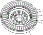
图5为本发明的定子组件的立体图。Fig. 5 is a perspective view of the stator assembly of the present invention.

图6为本发明的定子组件的结构示意图。Fig. 6 is a schematic structural view of the stator assembly of the present invention.

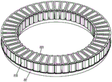
图7为本发明的定子组件中定子绕线柱上装配有线圈绕组时的俯视图。Fig. 7 is a top view of the stator assembly of the present invention when coil windings are assembled on the stator winding posts.

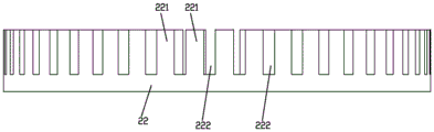
图8为本发明的定子组件中定子绕线柱上没有装配线圈绕组时的侧视图。Fig. 8 is a side view of the stator assembly of the present invention when no coil winding is assembled on the stator winding post.

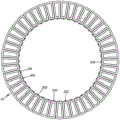
图9为本发明的定子组件中定子绕线柱上没有装配线圈绕组时的俯视图。Fig. 9 is a top view of the stator assembly of the present invention when no coil winding is installed on the stator winding post.

图10为本发明的扇叶的结构示意图。Fig. 10 is a schematic structural view of the fan blade of the present invention.

图11为本发明的扇叶的侧视图。Fig. 11 is a side view of the fan blade of the present invention.

图12为本发明的扇叶的爆炸图之一。Fig. 12 is one of the exploded views of the fan blade of the present invention.

图13为本发明的扇叶的爆炸图之二。Fig. 13 is the second exploded view of the fan blade of the present invention.

图14为本发明的扰流板的立体图。Fig. 14 is a perspective view of the spoiler of the present invention.

图15为本发明的扰流板的主视图。Fig. 15 is a front view of the spoiler of the present invention.

图16为本发明的扰流板从其尾端方向观察时的示意图。Fig. 16 is a schematic diagram of the spoiler of the present invention viewed from the direction of its tail end.

图17为本发明的扰流板的剖视图。Fig. 17 is a sectional view of the spoiler of the present invention.

图18为本发明的仰视图。Figure 18 is a bottom view of the present invention.

图19为本发明的轴向磁通电机另一实施例的剖视图Fig. 19 is a sectional view of another embodiment of the axial flux motor of the present invention

【具体实施方式】【Detailed ways】

下面结合附图1-19对本发明的实施方式作详细说明。Embodiments of the present invention will be described in detail below in conjunction with accompanying drawings 1-19.

如图1-18所示,本发明一种基于轴向磁通电机的吊扇,包括定子轴1、相对固定地连接在定子轴1上的定子组件2、位于定子组件2上方且可相对定子轴1转动的转子组件3和呈圆周分布于转子组件3上的若干片扇叶5,每一所述扇叶5通过扇叶连接件4与转子组件3连接,所述扇叶连接件4具有连接部和插接部,所述扇叶连接件4连接部与转子组件3相对固定连接,所述扇叶连接件4插接部伸入扇叶5内而与扇叶5相对固定连接。本发明相对现有技术中采用径向磁通电机来带动扇叶转动而言,本发明采用轴向磁通电机来带动扇叶转动,具有转动效率高,运行平稳,体积整体相对较小,安全可靠的特点;其中所述扇叶连接件连接部与转子组件相对固定连接,所述扇叶连接件插接部伸入扇叶内而与扇叶相对固定连接,能够避免现有技术中扇叶连接件直接与扇叶表面连接而容易造成扇叶损伤的问题,同时扇叶连接件也能提高扇叶的结构强度,降低扇叶发生形变的概率。As shown in Figures 1-18, a ceiling fan based on an axial flux motor according to the present invention includes a stator shaft 1, a stator assembly 2 relatively fixedly connected to the stator shaft 1, and a stator assembly 2 located above the stator assembly 2 that can be positioned relative to the stator shaft. 1 Rotating rotor assembly 3 and several fan blades 5 distributed on the rotor assembly 3 in a circumferential manner, each of the fan blades 5 is connected to the rotor assembly 3 through a fan blade connector 4, and the fan blade connector 4 has a connection The connection part of the blade connector 4 is relatively fixedly connected with the rotor assembly 3 , and the insertion part of the blade connector 4 protrudes into the fan blade 5 and is relatively fixedly connected with the fan blade 5 . Compared with the radial flux motor used in the prior art to drive the fan blades to rotate, the present invention uses an axial flux motor to drive the fan blades to rotate, which has the advantages of high rotation efficiency, stable operation, relatively small overall volume, and safety. Reliable features; wherein the connecting part of the fan blade connector is relatively fixedly connected with the rotor assembly, and the insertion part of the fan blade connector protrudes into the fan blade and is relatively fixedly connected with the fan blade, which can avoid the fan blade in the prior art. The connecting piece is directly connected to the surface of the fan blade, which is likely to cause damage to the fan blade. At the same time, the fan blade connecting piece can also improve the structural strength of the fan blade and reduce the probability of deformation of the fan blade.

如图1所示,为了使得吊扇运行更加平稳,所述扇叶数量为偶数片,如使用扇叶数量4、6、8片等。As shown in FIG. 1 , in order to make the ceiling fan run more smoothly, the number of fan blades is an even number, for example, the number of fan blades is 4, 6, or 8.

如图1-9所示,所述定子组件2包括呈圆环状的定子环22和线圈绕组23,所述定子环22在圆周方向上均匀分布有沿轴向延伸的定子绕线柱221,所述定子环22上且位于相邻两所述定子绕线柱221之间形成有定子容纳槽222,所述定子容纳槽222沿径向方向的两端呈开口设置,所述定子容纳槽222相对两侧面为直面,所述线圈绕组23包括线圈本体231和设在线圈本体231中部上用于与定子绕线柱221配合连接的线圈通孔232,能够使得装配在定子绕线柱上的线圈绕组与定子绕线柱贴合更加紧密,进而使得线圈绕组与定子绕线柱连接更加稳固,同时可高效地将线圈绕组与定子绕线柱进行装配,且在单位空间内最大化地确保了线圈绕组的圈数,以提高磁通量,进而改善轴向磁通电机的输出功率、扭矩,并确保轴向磁通电机整机体积最小化,有效降低生产制造成本。As shown in Figures 1-9, the stator assembly 2 includes an annular stator ring 22 and a coil winding 23, and the stator ring 22 is evenly distributed in the circumferential direction with axially extending stator winding posts 221, A stator receiving groove 222 is formed on the stator ring 22 and between two adjacent stator winding posts 221. The two ends of the stator receiving groove 222 along the radial direction are open. The stator receiving groove 222 The opposite sides are straight faces, and the coil winding 23 includes a coil body 231 and a coil through hole 232 arranged in the middle of the coil body 231 for cooperating with the stator winding post 221, so that the coil assembled on the stator winding post 221 can The winding and the stator winding post fit more closely, which makes the connection between the coil winding and the stator winding post more stable. At the same time, the coil winding and the stator winding post can be assembled efficiently, and the coil winding is ensured to the maximum extent in the unit space. The number of turns of the windings is used to increase the magnetic flux, thereby improving the output power and torque of the axial flux motor, and ensuring that the overall volume of the axial flux motor is minimized, effectively reducing the manufacturing cost.

如图1-9所示,所述定子绕线柱221具有内圆侧壁2211、第一直面侧壁2212、外圆侧壁2213和第二直面侧壁2214,每一个所述定子容纳槽222位于相邻两所述定子绕线柱221之间且由一所述定子绕线柱221的第一直面侧壁2212与另一所述定子绕线柱221的第二直面侧壁2214形成。As shown in Figures 1-9, the stator winding post 221 has an inner circular side wall 2211, a first straight side wall 2212, an outer circular side wall 2213 and a second straight side wall 2214, each of the stator receiving slots 222 is located between two adjacent stator winding posts 221 and is formed by the first straight side wall 2212 of one stator winding post 221 and the second straight side wall 2214 of the other stator winding post 221 .

所述内圆侧壁2211、第一直面侧壁2212、外圆侧壁2213和第二直面侧壁2214之间的棱边呈弧形设置,能够增大棱边与线圈绕组的接触面积,避免棱边划伤线圈绕组,起到保护作用,延长线圈绕组使用寿命和确保定子组件工作稳定性。The edges between the inner circular side wall 2211, the first straight side wall 2212, the outer circular side wall 2213 and the second straight side wall 2214 are arranged in an arc shape, which can increase the contact area between the edge and the coil winding, Avoid scratching the coil winding by the edge, play a protective role, prolong the service life of the coil winding and ensure the working stability of the stator assembly.

如图1-9所示,所述定子绕线柱221的中心线2215经过所述定子环22的圆心,且每一个所述定子绕线柱221的第一直面侧壁2212和第二直面侧壁2214向定子环22圆心延伸而相交于一平行于所述定子环22中心轴线的直线。As shown in Figures 1-9, the center line 2215 of the stator winding post 221 passes through the center of the stator ring 22, and the first straight side wall 2212 and the second straight side wall 2212 of each stator winding post 221 The sidewall 2214 extends toward the center of the stator ring 22 and intersects with a straight line parallel to the central axis of the stator ring 22 .

如图1-9所示,为了增加定子绕线柱和线圈绕组的数量以增加磁通量,改善轴向磁通电机的输出功率、扭矩,相邻两所述定子绕线柱221的中心线2215之间的夹角为α,则有3°≤α≤15°。As shown in Figure 1-9, in order to increase the number of stator winding posts and coil windings to increase the magnetic flux and improve the output power and torque of the axial flux motor, between the centerlines 2215 of the two adjacent stator winding posts 221 The angle between them is α, then there are 3°≤α≤15°.

优选的,相邻两所述定子绕线柱221的中心线2215之间的夹角α为8°,所述定子绕线柱11为52根,则线圈绕组为52组,能够增加定子绕线柱和线圈绕组的数量以增加磁通量,同时保证定子环整体平衡和定子组件工作稳定。Preferably, the included angle α between the centerlines 2215 of two adjacent stator winding posts 221 is 8°, and if there are 52 stator winding posts 11, there are 52 sets of coil windings, which can increase the number of stator winding posts 221. The number of columns and coil windings is used to increase the magnetic flux, while ensuring the overall balance of the stator ring and stable operation of the stator assembly.

如图1-9所示,所述定子绕线柱221横截面呈梯形设置,相对应地所述线圈通孔232形状与定子绕线柱221相适配,能够增大定子绕线柱与绕线绕组接触面积,使得二者连接更加稳固。As shown in Figure 1-9, the cross-section of the stator winding post 221 is set in a trapezoidal shape, and the shape of the coil through hole 232 is correspondingly adapted to the stator winding post 221, which can increase the size of the stator winding post and the coil. The contact area of the wire winding makes the connection between the two more stable.

如图1-9所示,所述线圈绕组23通过黏胶而固定套接于定子绕线柱221上,能够使得二者连接更加牢固,避免线圈绕组相对定子绕线柱出现窜动等现象而导致定子组件工作不稳定的问题。每一线圈绕组23的接线端子233均位于定子环22内侧而相应连接,能够避免接线端子233不处于定子环22同一侧而存在连接成本高和连接复杂的问题,方便接线端子233连接,另外还对接线端子233起到保护作用。As shown in Figures 1-9, the coil winding 23 is fixedly socketed on the stator winding post 221 through glue, which can make the connection between the two more firm and prevent the coil winding from moving relative to the stator winding post. Problems that cause unstable operation of the stator assembly. The connection terminals 233 of each coil winding 23 are located inside the stator ring 22 and connected accordingly, which can avoid the problems of high connection cost and complicated connection caused by the connection terminals 233 not being on the same side of the stator ring 22, and facilitate the connection of the connection terminals 233. Protect the connection terminal 233.

如图1-9所示,所述定子组件2还包括与定子环22相适配而连接的定子底壳21,所述定子环22底部直接或间接抵触于定子底壳21内底而进行热传导,能够对定子组件2起到保护作用,同时能够更好的对定子环22进行散热,避免轴向磁通电机工作时,定子组件2温度过高而影响轴向磁通电机输出功率和烧坏轴向磁通电机。As shown in Figures 1-9, the stator assembly 2 further includes a stator bottom case 21 adapted and connected to the stator ring 22, and the bottom of the stator ring 22 directly or indirectly touches the inner bottom of the stator bottom case 21 for heat conduction , can protect the stator assembly 2, and at the same time can better dissipate heat from the stator ring 22, avoiding that when the axial flux motor is working, the temperature of the stator assembly 2 is too high, which will affect the output power and burnout of the axial flux motor Axial flux motor.

如图1-9所示,所述定子底壳21包括底壳外环212和位于底壳外环212内侧的底壳内环213,所述定子底壳21上且位于底壳外环212与底壳内环213之间形成有用于安装定子环22的底壳安装槽214,安装便捷,所述定子环22与底壳内环213之间形成有用于填充胶水以将每一线圈绕组23的接线端子233固定的底壳填充槽215,且每一线圈绕组23的接线端子233位于底壳填充槽215内,能够避免出现接线端子233晃动、松动等现象而导致接触不良的问题,使得接线端子233更加稳固以保证定子组件工作稳定,确保产品质量。As shown in Figures 1-9, the stator bottom case 21 includes a bottom case outer ring 212 and a bottom case inner ring 213 located inside the bottom case outer ring 212, and the stator bottom case 21 is located on the bottom case outer ring 212 and the bottom case inner ring 213. A bottom case installation groove 214 for installing the stator ring 22 is formed between the inner ring 213 of the bottom case, and the installation is convenient. The bottom casing filling groove 215 where the connecting terminal 233 is fixed, and the connecting terminal 233 of each coil winding 23 is located in the bottom casing filling groove 215, which can avoid the problem of poor contact caused by the shaking and loosening of the connecting terminal 233, so that the connecting terminal 233 is more stable to ensure the stable operation of the stator assembly and ensure product quality.

如图18所示,所述定子底壳21外底上相对应于定子环22底部位置设有若干片底壳散热片216,能够增大散热面积,提高散热效率。As shown in FIG. 18 , on the outer bottom of the stator bottom case 21 corresponding to the bottom of the stator ring 22 , there are several bottom case cooling fins 216 , which can increase the heat dissipation area and improve the heat dissipation efficiency.

如图18所示,为了更好的散热,所述底壳散热片216包括设在定子环22底部位置上且沿定子底壳21周向间隔设置的周向散热凸筋和设在定子环22底部位置上且沿定子底壳21径向间隔设置的径向散热凸筋,所述周向散热凸筋与径向散热凸筋交叉设置。As shown in Figure 18, in order to better dissipate heat, the bottom case cooling fins 216 include circumferential heat dissipation ribs arranged at the bottom of the stator ring 22 and arranged at intervals along the circumferential direction of the stator bottom case 21 and arranged on the stator ring 22 The radial heat dissipation ribs arranged at intervals along the radial direction of the bottom position of the stator bottom case 21 , and the circumferential heat dissipation ribs are intersected with the radial heat dissipation ribs.

如图1-9所示,所述定子组件2包括定子底壳21和与定子底壳21连接的定子环22,所述定子底壳21底壁上设有用于与定子轴1配合连接的底壳通孔211,所述定子轴1下端部具有与其一体成型的定子轴肩11,且当所述定子组件2通过底壳通孔211与定子轴1连接时,所述定子轴肩11的内侧面抵靠于底壳通孔211外侧面以防止定子组件2相对定子轴1沿轴向向下窜动,能够使得定子组件与定子轴连接更加牢固可靠和结构更加稳定,另外定子轴肩与定子轴一体成型,具有结构简单,易于成型制造的特点。如图3-5所示,所述底壳通孔211位于底壳内环213内侧。As shown in Figures 1-9, the stator assembly 2 includes a stator bottom case 21 and a stator ring 22 connected to the stator bottom case 21, and the bottom wall of the stator bottom case 21 is provided with a bottom for mating connection with the stator shaft 1 Shell through hole 211, the lower end of the stator shaft 1 has a stator shoulder 11 integrally formed with it, and when the stator assembly 2 is connected to the stator shaft 1 through the bottom case through hole 211, the inner part of the stator shoulder 11 The side is against the outer surface of the through hole 211 of the bottom case to prevent the stator assembly 2 from axially moving downward relative to the stator shaft 1, which can make the connection between the stator assembly and the stator shaft more reliable and stable and the structure more stable. In addition, the stator shoulder and the stator The shaft is integrally formed, which has the characteristics of simple structure and easy forming and manufacturing. As shown in FIGS. 3-5 , the through hole 211 of the bottom case is located inside the inner ring 213 of the bottom case.

如图1-9所示,为了提高连接强度,所述定子底壳21上且沿底壳通孔211周侧设有沿径向延伸的底壳加强筋2110。As shown in FIGS. 1-9 , in order to improve the connection strength, bottom casing reinforcing ribs 2110 extending radially are provided on the stator bottom casing 21 and along the periphery of the bottom casing through hole 211 .

在一些实施方式中,所述定子轴肩11数量为多个,多个所述定子轴肩11沿轴向呈阶梯状位于定子轴11下端部以防止定子组件相对定子轴沿轴向向下窜动,能够起到多重支撑限位作用,提高定子轴与定子组件连接结构强度,保证定子轴与定子组件连接更加牢固、可靠,安全性高。In some embodiments, the number of the stator shoulders 11 is multiple, and the plurality of stator shoulders 11 are located at the lower end of the stator shaft 11 in a stepped shape in the axial direction to prevent the stator assembly from axially moving downward relative to the stator shaft. It can play the role of multiple support and limit, improve the structural strength of the connection between the stator shaft and the stator assembly, and ensure that the connection between the stator shaft and the stator assembly is more firm, reliable and safe.

为了使得定子底壳相对定子轴连接牢固之阻止定子底壳21相对定子轴1转动,所述定子底壳21的底壳通孔211与定子轴1过盈配合。In order to make the stator bottom case firmly connected to the stator shaft and prevent the stator bottom case 21 from rotating relative to the stator shaft 1 , the bottom case through hole 211 of the stator bottom case 21 is interference fit with the stator shaft 1 .

如图1-9所示,为了提高连接强度和更好配合定子底壳以防止定子底壳沿轴向向下窜动,所述定子轴1下端部且位于定子轴肩11上方设有定子法兰盖12,所述定子法兰盖12中部设有用于与定子轴1配合连接的法兰通孔121,当定子法兰盖12通过法兰通孔121套设于定子轴1上且定子底壳21通过底壳通孔211套设于定子轴1上且位于定子法兰盖12上方时,所述定子轴肩11内侧面与法兰通孔121外侧面抵靠,所述定子法兰盖12上端面与底壳通孔211外侧面抵靠以防止定子组件2相对定子轴1沿轴向向下窜动。在本实施方式中,所述定子底壳21与定子法兰盖12通过螺栓/铆钉等连接紧固件相对固定连接。As shown in Figure 1-9, in order to improve the connection strength and better match the stator bottom case to prevent the stator bottom case from moving downward in the axial direction, a stator method is provided at the lower end of the stator shaft 1 and above the stator shoulder 11. The flange cover 12, the middle part of the stator flange cover 12 is provided with a flange through hole 121 for cooperating with the stator shaft 1, when the stator flange cover 12 is sleeved on the stator shaft 1 through the flange through hole 121 and the bottom of the stator When the shell 21 is sleeved on the stator shaft 1 through the through hole 211 of the bottom shell and is located above the stator flange cover 12, the inner surface of the stator shoulder 11 abuts against the outer surface of the flange through hole 121, and the stator flange cover The upper end surface of 12 abuts against the outer surface of the through hole 211 of the bottom case to prevent the stator assembly 2 from axially moving downward relative to the stator shaft 1 . In this embodiment, the stator bottom case 21 is relatively fixedly connected to the stator flange cover 12 by bolts/rivets and other fasteners.

如图1-9所示,所述定子底壳21外侧面形成有用于容纳定子法兰盖12的底壳容纳腔,能够使得轴向磁通电机结构更加紧凑,连接结构更加稳固。As shown in FIGS. 1-9 , the outer surface of the stator bottom case 21 is formed with a bottom case accommodation chamber for accommodating the stator flange cover 12 , which can make the structure of the axial flux motor more compact and the connection structure more stable.

所述定子法兰盖12与定子轴1可拆卸地连接,所述定子法兰盖12的法兰通孔121与定子轴1过盈配合或通过花键连接,限制定子法兰盖12相对定子轴1转动。在生产加工时,由于定子法兰盖横向宽度和定子轴横向宽度不一致,因此将定子轴和定子法兰盖分开生产制造,能够节省制造成本。The stator flange cover 12 is detachably connected to the stator shaft 1, and the flange through hole 121 of the stator flange cover 12 is interference-fitted with the stator shaft 1 or connected by a spline, so that the relative stator flange cover 12 is limited. Axis 1 turns. During production and processing, since the transverse width of the stator flange cover is inconsistent with the transverse width of the stator shaft, the stator shaft and the stator flange cover are manufactured separately, which can save manufacturing costs.

如图1-4所示,所述转子组件3包括位于定子组件2上方的转子盘31,所述转子盘31下表面上相对应设有用于与线圈绕组23配合使用的磁瓦,所述转子盘31上设有与定子轴1配合的转子通孔311,所述转子盘31与定子轴1之间连接有转子转动件32,所述转子盘31与定子轴1之间或转子盘31与定子组件2之间设有用于支撑转子盘31相对定子轴1平稳转动的支撑转动组件33,通过支撑转动组件和转子转动件配合使用,支撑转动组件支撑转子盘能够减小转子盘对转子转动件的作用力,使得转子盘相对定子轴转动顺畅、平稳。本实施例中,所述磁瓦形状为梯形等,能够增大磁通量,提高吊扇运转效率。As shown in Figures 1-4, the rotor assembly 3 includes a rotor disk 31 located above the stator assembly 2, the lower surface of the rotor disk 31 is correspondingly provided with magnetic tiles for use with the coil winding 23, the rotor The disc 31 is provided with a rotor through hole 311 matching with the stator shaft 1, and a rotor rotating part 32 is connected between the rotor disc 31 and the stator shaft 1, and between the rotor disc 31 and the stator shaft 1 or between the rotor disc 31 and the stator A supporting and rotating assembly 33 is provided between the assemblies 2 for supporting the rotor disk 31 to rotate smoothly relative to the stator shaft 1. By using the supporting and rotating assembly in conjunction with the rotor rotating member, the supporting rotating assembly can support the rotor disk to reduce the impact of the rotor disk on the rotor rotating member. The force makes the rotor disk rotate smoothly and steadily relative to the stator shaft. In this embodiment, the shape of the magnetic tile is trapezoidal, etc., which can increase the magnetic flux and improve the operating efficiency of the ceiling fan.

如图1-4所示,优选的,所述转子转动件32为设在转子通孔311与定子轴1之间且向心力沿轴向向下的向下推力轴承,所述向下推力轴承内圈与定子轴1相对固定连接,所述向下推力轴承外圈与转子通孔311内壁相对固定连接,能够防止转子盘在转动过程中出现沿轴向向上窜动现象,使得转子盘转动更加平稳、顺畅。As shown in Figures 1-4, preferably, the rotor rotating member 32 is a downward thrust bearing arranged between the rotor through hole 311 and the stator shaft 1 and the centripetal force is axially downward. The outer ring of the downward thrust bearing is relatively fixedly connected with the stator shaft 1, and the outer ring of the downward thrust bearing is relatively fixedly connected with the inner wall of the rotor through hole 311, which can prevent the phenomenon of upward movement of the rotor disk in the axial direction during the rotation process, and make the rotation of the rotor disk more stable. , smooth.

如图1-4所示,优选的,所述支撑转动组件33包括设在转子盘31与定子组件2之间的平面轴承,所述平面轴承下支撑环与定子组件2相对固定连接,所述平面轴承上支撑环与转子盘31相对固定连接。如图4所示,所述平面轴承安装于定子底壳21上且位于底壳内环213内侧,能够更好支撑转子盘31,提高转子盘结构强度,同时使得转子盘相对定子轴更加平稳顺畅转动。As shown in Figures 1-4, preferably, the supporting and rotating assembly 33 includes a plane bearing arranged between the rotor disk 31 and the stator assembly 2, the support ring of the plane bearing is relatively fixedly connected with the stator assembly 2, and the The support ring on the plane bearing is relatively fixedly connected with the rotor disc 31 . As shown in FIG. 4, the plane bearing is installed on the stator bottom case 21 and is located inside the bottom case inner ring 213, which can better support the rotor disk 31, improve the structural strength of the rotor disk, and at the same time make the rotor disk more stable and smooth relative to the stator shaft. turn.

如图19所示,所述支撑转动组件33包括设在转子盘31与定子轴1之间且向下力沿轴向向上的向上推力轴承,所述向上推力轴承位于向下推力轴承下方,所述向上推力轴承内圈与定子轴1相对固定连接,所述向上推力轴承外圈与转子通孔311内壁相对固定连接。As shown in FIG. 19 , the supporting and rotating assembly 33 includes an upward thrust bearing arranged between the rotor disk 31 and the stator shaft 1 and the downward force is axially upward. The upward thrust bearing is located below the downward thrust bearing, so The inner ring of the upward thrust bearing is relatively fixedly connected to the stator shaft 1 , and the outer ring of the upward thrust bearing is relatively fixedly connected to the inner wall of the rotor through hole 311 .

如图1-4所示,所述定子底壳21上且所述平面轴承与向下推力轴承之间设有支撑连接件34,所述支撑连接件34中部上设有支撑连接通孔341,所述支撑连接通孔341内壁与向下推力轴承外圈相对固定连接,所述支撑连接件34外壁与平面轴承上支撑环内壁相对固定连接,所述支撑连接件34上表面支撑所述转子盘31下表面,能够使得本发明结构更加稳定、运行更好平稳和更好支撑转子盘。As shown in Figures 1-4, a support connector 34 is provided on the stator bottom case 21 and between the plane bearing and the downward thrust bearing, and a support connection through hole 341 is provided in the middle of the support connector 34, The inner wall of the support connection through hole 341 is relatively fixedly connected to the outer ring of the downward thrust bearing, the outer wall of the support connector 34 is relatively fixedly connected to the inner wall of the upper support ring of the plane bearing, and the upper surface of the support connector 34 supports the rotor disk 31 lower surface, which can make the structure of the present invention more stable, run more smoothly and better support the rotor disk.

如图1-4所示,为了更好连接安装,所述转子盘31上表面呈圆周方向间隔地分布有用于供扇叶连接件4连接部安装定位的安装定位槽312,所述转子盘31上且位于安装定位槽312内和扇叶连接件4连接部分别设有供螺栓/铆钉穿设以将扇叶连接件4与转子盘31固定连接的安装通孔。As shown in Figures 1-4, for better connection and installation, the upper surface of the rotor disk 31 is distributed with installation and positioning grooves 312 at intervals in the circumferential direction for the installation and positioning of the connecting part of the fan blade connector 4. The rotor disk 31 Mounting through holes are respectively provided on the top and in the installation positioning groove 312 and at the connecting portion of the fan blade connector 4 for bolts/rivets to connect the fan blade connector 4 and the rotor disk 31 fixedly.

如图1-4所示,为了更好确保扇叶连接件4与转子盘31连接更加牢固、稳定,所述安装定位槽312包括设在转子盘31上且用于限制扇叶连接件4沿转子盘31周向活动的两定位侧壁3121和设在转子盘31上且位于定位侧壁3121内端侧以用于限制扇叶连接件4沿转子盘31径向活动的定位凸起3122。As shown in Figures 1-4, in order to better ensure a firmer and more stable connection between the blade connector 4 and the rotor disk 31, the installation positioning groove 312 is provided on the rotor disk 31 and is used to limit the blade connector 4 along the Two positioning sidewalls 3121 of the rotor disk 31 move in the circumferential direction and a positioning protrusion 3122 provided on the rotor disk 31 and located at the inner end side of the positioning sidewalls 3121 for restricting the radial movement of the blade connector 4 along the rotor disk 31 .

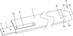
如图1、10-17所示,所述扇叶5呈中空设置,所述扇叶5上内壁与下内壁之间间隔地设有左连接内筋51和右连接内筋52,所述左连接内筋51和右连接内筋52上相向地设有左限位槽511和右限位槽521,所述左限位槽511与右限位槽521之间形成有供扇叶连接件4插接部插接定位的定位空间53;所述扇叶5上且相应位于定位空间53处设有扇叶安装孔531;所述扇叶连接件4上设有当扇叶连接件4插接部插接于定位空间53内时用于与扇叶安装孔531对齐以连接的连接件安装孔42,所述扇叶连接件4连接部上还设有用于与转子组件3连接配合的连接件连孔41;还包括能同时穿设于扇叶安装孔531和连接件安装孔42内以将扇叶连接件4与扇叶5固定连接的连接螺栓/铆钉。本发明通过在所述扇叶5上内壁与下内壁之间间隔地设有左连接内筋51和右连接内筋52,能够降低扇叶在转动过程中被风作用下而发生形变等现象,提高扇叶结构强度,另外左连接内筋51和右连接内筋52均位于扇叶内腔,在扇叶相同体积大小的情况下,本发明将内筋内置相对比内筋外置的结构,具有扇叶整体体积小,便于存放、运输的特点;所述左限位槽511与右限位槽521之间形成有供扇叶连接件4插接部插接定位的定位空间53,通过将扇叶连接件插接部插接于定位空间内,能够有效解决现有技术中将扇叶连接件直接与扇叶外表面连接而造成叶片损伤、影响扇叶使用寿命的问题,同时扇叶在转动过程中能够减少连接螺栓/铆钉等紧固件的受力,有效避免扇叶连接件与扇叶发生偏移及紧固件发生变形或机械疲劳,提高扇叶连接件与扇叶之间的连接强度,连接稳定性;同时定位空间对扇叶连接件也起到导向、定位作用,便于安装。As shown in Figures 1 and 10-17, the fan blade 5 is hollow, and a left connecting inner rib 51 and a right connecting inner rib 52 are arranged between the upper inner wall and the lower inner wall of the fan blade 5 at intervals. The connecting inner rib 51 and the right connecting inner rib 52 are provided with a left limiting groove 511 and a right limiting groove 521 facing each other, and a fan blade connector 4 is formed between the left limiting groove 511 and the right limiting groove 521. The positioning space 53 for plugging and positioning of the socket part; the fan blade 5 is provided with a fan blade installation hole 531 correspondingly located at the positioning space 53; When the part is plugged into the positioning space 53, it is used to align with the fan blade installation hole 531 for connection. The connecting part of the fan blade connector 4 is also provided with a connector for connecting with the rotor assembly The connecting hole 41 also includes connecting bolts/rivets that can be passed through the blade installation hole 531 and the connector installation hole 42 to securely connect the fan blade connector 4 and the fan blade 5 . In the present invention, the left connecting inner rib 51 and the right connecting inner rib 52 are provided at intervals between the upper inner wall and the lower inner wall of the fan blade 5, which can reduce the deformation of the fan blade under the action of the wind during the rotation process. Improve the structural strength of the fan blade. In addition, the left connecting inner rib 51 and the right connecting inner rib 52 are located in the inner cavity of the fan blade. In the case of the same volume and size of the fan blade, the present invention has a structure in which the inner rib is built-in compared to the inner rib. The overall volume of the fan blade is small, which is convenient for storage and transportation; a positioning space 53 is formed between the left limiting groove 511 and the right limiting groove 521 for the insertion and positioning of the blade connector 4 . The plug-in part of the blade connector is plugged into the positioning space, which can effectively solve the problem in the prior art that the fan blade connector is directly connected to the outer surface of the fan blade, causing damage to the blade and affecting the service life of the fan blade. During the process, it can reduce the force on the fasteners such as connecting bolts/rivets, effectively avoid the deviation between the blade connector and the blade, the deformation of the fastener or mechanical fatigue, and improve the connection between the blade connector and the blade. Strength and connection stability; at the same time, the positioning space also plays a role in guiding and positioning the fan blade connector, which is convenient for installation.

如图1、10-17所示,所述扇叶5上内壁和/或下内壁设有位于定位空间53内且当扇叶连接件4插接部插接于定位空间53内时用于与扇叶连接件4插接部抵接的加强内筋54,能够进一步地提高扇叶的结构强度,同时也提高扇叶与扇叶连接件之间的结构强度,保证扇叶结构的稳定性。As shown in Figures 1, 10-17, the upper inner wall and/or the lower inner wall of the fan blade 5 are located in the positioning space 53 and are used to communicate with the positioning space 53 when the blade connector 4 is inserted into the positioning space 53 The reinforced inner ribs 54 abutting against the inserting portion of the fan blade connector 4 can further improve the structural strength of the fan blade, and at the same time improve the structural strength between the fan blade and the fan blade connector to ensure the stability of the fan blade structure.

如图1、10-17所示,所述扇叶安装孔531位于加强内筋54位置处,增强扇叶安装孔531侧壁与连接螺栓/铆钉间连接强度,提高结构稳定性。As shown in Figures 1 and 10-17, the fan blade installation hole 531 is located at the position of the reinforced inner rib 54, which enhances the connection strength between the side wall of the fan blade installation hole 531 and the connecting bolt/rivet, and improves the structural stability.

如图1、10-17所示,为了进一步提高扇叶连接件与扇叶连接强度,所述扇叶连接件4上设有当扇叶连接件4插接部插接于定位空间53内时用于与加强内筋54抵接的连接件垫片,所述连接件垫片上设有与连接件安装孔42对齐的垫片安装孔,图中未表现出来。在组装时,可以通过胶水粘接方式将连接件垫片固定于扇叶连接件4上,此刻垫片安装孔与连接件安装孔42对齐,接着操作扇叶连接件4插接于定位空间53内,直至连接件安装孔42与扇叶安装孔531对齐,之后将连接螺栓/铆钉同时穿设于扇叶安装孔531、垫片安装孔及连接件安装孔42内以将扇叶连接件4、连接件垫片及扇叶5固定连接。As shown in Figures 1 and 10-17, in order to further improve the connection strength between the blade connector and the blade, the blade connector 4 is provided with a The connector gasket for abutting against the reinforcing inner rib 54 is provided with a gasket installation hole aligned with the connector installation hole 42 , which is not shown in the figure. During assembly, the connector gasket can be fixed on the fan blade connector 4 by glue bonding. At this moment, the gasket installation hole is aligned with the connector installation hole 42, and then the fan blade connector 4 is inserted into the positioning space 53 until the connector installation hole 42 is aligned with the fan blade installation hole 531, and then the connecting bolts/rivets are simultaneously inserted in the fan blade installation hole 531, the gasket installation hole and the connector installation hole 42 to secure the fan blade connector 4 , the connector gasket and the fan blade 5 are fixedly connected.

进一步的,所述连接件垫片为硅胶或橡胶等可形变材料制成,能够避免扇叶连接件与扇叶直接刚性接触而相互磨损,延长二者使用寿命,另外能够起到减震作用,减少轴向磁通电机通过扇叶连接件对扇叶产生的振动,确保扇叶平稳转动。Further, the connector gasket is made of deformable materials such as silica gel or rubber, which can prevent the fan blade connector from being in direct rigid contact with the fan blade and cause mutual abrasion, prolong the service life of the two, and can also play a shock absorbing role. Reduce the vibration of the fan blade caused by the axial flux motor through the fan blade connector, and ensure the smooth rotation of the fan blade.

如图1、10-17所示,为了进一步提高扇叶连接件与扇叶连接强度,所述扇叶5上设有扇叶垫块55,所述扇叶垫块55上设有与扇叶安装孔531对齐以连接的垫块安装孔551。在本实施方式中,如图10、11所示,所述扇叶垫块55位于扇叶5外壁上。As shown in Figure 1, 10-17, in order to further improve the connection strength between the fan blade connector and the fan blade, the fan blade 5 is provided with a fan blade spacer 55, and the fan blade spacer 55 is provided with a The mounting holes 531 are aligned with the spacer mounting holes 551 for connection. In this embodiment, as shown in FIGS. 10 and 11 , the fan blade spacer 55 is located on the outer wall of the fan blade 5 .

如图1、10-17所示,为了使得扇叶结构更加稳定和减少组装步骤,所述扇叶5由铝制材料一体挤压成型。As shown in Figures 1, 10-17, in order to make the fan blade structure more stable and reduce assembly steps, the fan blade 5 is integrally extruded from aluminum material.

如图1、10-17所示,所述扇叶5长度为0.8~2.5m。优选的,所述扇叶5长度为1.35m,更好扰动空气,提高扰流效果,实现大面积吹风效果。As shown in Figures 1 and 10-17, the length of the fan blade 5 is 0.8-2.5m. Preferably, the length of the fan blade 5 is 1.35m, which can better disturb the air, improve the turbulence effect, and realize the large-area blowing effect.

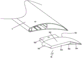
如图1、10-17所示,还包括连接在所述扇叶5尾端的扰流板56,所述扰流板56具有可与扇叶5尾端相接的连接端面561、与连接端面561相对的尾部端面563、位于连接端面561前端与尾部端面563前端之间的前端面562、位于连接端面561后端与尾部端面563后端之间的后端面564、扰流上表面565及扰流下表面566,所述后端面564由连接端面561往尾部端面563方向向上弯曲,所述扰流上表面565和扰流下表面566均由连接端面561往尾部端面563方向向上弯曲,所述扰流下表面566向扇叶5旋转方向倾斜设置。其在吊扇运转时,扰流板能够有效的切断扇叶尾部形成涡流,使得吊扇运转平稳,提高吊扇的运转效果,降低能耗;另外吊扇运转时,扇叶下表面和扰流下表面被风作用而使之具有一个向上力,由于扰流上表面由连接端面往尾部端面方向向上弯曲,使得扰流上表面能够更好与风接触而使扰流板具有一个向下力,则向下的力和向上的力相互抵消,从而降低扇叶在转动过程中的振动频率,保证扇叶转动平稳,进而使得扇叶之扇叶连接件与转子组件连接稳定;另外扰流下表面由连接端面往尾部端面方向向上弯曲,能够使经过扰流下表面的风往扇叶径向方向扩散,吹风范围更广,扰流效果更好。As shown in Figures 1, 10-17, it also includes a spoiler 56 connected to the tail end of the fan blade 5, and the spoiler 56 has a connection end surface 561 that can be connected to the tail end of the fan blade 5, and a connection end surface 561 relative to the tail end face 563, the front end face 562 between the front end of the connecting end face 561 and the front end of the tail end face 563, the rear end face 564 between the rear end of the connecting end face 561 and the rear end of the tail end face 563, the spoiler upper surface 565 and the spoiler Flow down surface 566, the rear end surface 564 is bent upward from the connection end surface 561 to the tail end surface 563, the spoiler upper surface 565 and the spoiler lower surface 566 are bent upward from the connection end surface 561 to the tail end surface 563, the spoiler bottom The surface 566 is inclined to the rotation direction of the fan blade 5 . When the ceiling fan is running, the spoiler can effectively cut off the vortex at the tail of the fan blade, so that the ceiling fan runs smoothly, improves the running effect of the ceiling fan, and reduces energy consumption; And make it have an upward force, because the upper surface of the spoiler is bent upward from the connecting end face to the tail end face, so that the upper surface of the spoiler can be better in contact with the wind and the spoiler has a downward force, then the downward force and the upward force cancel each other out, thereby reducing the vibration frequency of the fan blade during rotation, ensuring the smooth rotation of the fan blade, and then making the connection between the fan blade connecting piece of the fan blade and the rotor assembly stable; in addition, the lower surface of the spoiler is from the connecting end face to the tail end face The direction is bent upwards, which can make the wind passing through the lower surface of the spoiler diffuse toward the radial direction of the fan blade, so that the blowing range is wider and the spoiler effect is better.

如图1、10-17所示,为了方便后端面弯曲、扭曲,所述后端面564面积由连接端面561往尾部端面563方向逐渐增大。As shown in Figures 1 and 10-17, in order to facilitate the bending and twisting of the rear end surface, the area of the rear end surface 564 gradually increases from the connection end surface 561 to the tail end surface 563.

如图1、10-17所示,为了降低制造成本,所述连接端面561长度大于尾部端面563长度。本实施例中连接端面561的长度为连接端面561由前端面562往后端面564方向的长度,尾部端面563的长度为尾部端面563由前端面562往后端面564方向的长度。As shown in FIGS. 1 and 10-17 , in order to reduce manufacturing costs, the length of the connecting end surface 561 is greater than the length of the tail end surface 563 . In this embodiment, the length of the connection end surface 561 is the length of the connection end surface 561 from the front end surface 562 to the rear end surface 564, and the length of the tail end surface 563 is the length of the tail end surface 563 from the front end surface 562 to the rear end surface 564.

如图1、10-17所示,所述扰流板56通过插接件560插接于扇叶5尾端内,所述插接件560与扇叶5之间通过螺钉/铆钉等紧固件以将二者固定连接,能够使得扰流板与扇叶连接更加牢固,同时方便扰流板与扇叶拆装。本实施例中插接件560与扇叶5之间的连接结构和扇叶连接件4与扇叶4之间的连接结构相同,此处不再累述。As shown in Figures 1 and 10-17, the spoiler 56 is plugged into the tail end of the fan blade 5 through the connector 560, and the connector 560 and the fan blade 5 are fastened by screws/rivets, etc. The two parts are fixedly connected, which can make the connection between the spoiler and the fan blade more firm, and at the same time facilitate the disassembly and assembly of the spoiler and the fan blade. The connection structure between the plug connector 560 and the fan blade 5 in this embodiment is the same as the connection structure between the fan blade connector 4 and the fan blade 4 , and will not be repeated here.

Claims (10)

1.一种基于轴向磁通电机的吊扇,其特征在于包括定子轴(1)、相对固定地连接在定子轴(1)上的定子组件(2)、位于定子组件(2)上方且可相对定子轴(1)转动的转子组件(3)和呈圆周分布于转子组件(3)上的若干片扇叶(5),每一所述扇叶(5)通过扇叶连接件(4)与转子组件(3)连接,所述扇叶连接件(4)具有连接部和插接部,所述扇叶连接件(4)连接部与转子组件(3)相对固定连接,所述扇叶连接件(4)插接部伸入扇叶(5)内而与扇叶(5)相对固定连接。1. A ceiling fan based on an axial flux motor, characterized in that it comprises a stator shaft (1), a stator assembly (2) relatively fixedly connected to the stator shaft (1), positioned above the stator assembly (2) and can be A rotor assembly (3) rotating relative to the stator shaft (1) and several blades (5) circumferentially distributed on the rotor assembly (3), each of the blades (5) passing through a blade connector (4) Connected with the rotor assembly (3), the fan blade connector (4) has a connecting part and a plug-in part, and the connecting part of the fan blade connector (4) is relatively fixedly connected with the rotor assembly (3), and the fan blade The insertion part of the connector (4) protrudes into the fan blade (5) and is relatively fixedly connected with the fan blade (5). 2.根据权利要求1所述一种基于轴向磁通电机的吊扇,其特征在于所述定子组件(2)包括呈圆环状的定子环(22)和线圈绕组(23),所述定子环(22)在圆周方向上均匀分布有沿轴向延伸的定子绕线柱(221),所述定子环(22)上且位于相邻两所述定子绕线柱(221)之间形成有定子容纳槽(222),所述定子容纳槽(222)沿径向方向的两端呈开口设置,所述定子容纳槽(222)相对两侧面为直面,所述线圈绕组(23)包括线圈本体(231)和设在线圈本体(231)中部上用于与定子绕线柱(221)配合连接的线圈通孔(232)。2. A ceiling fan based on an axial flux motor according to claim 1, characterized in that the stator assembly (2) includes an annular stator ring (22) and a coil winding (23), and the stator The ring (22) is evenly distributed in the circumferential direction with axially extending stator winding posts (221), and the stator ring (22) is formed between two adjacent stator winding posts (221). The stator accommodation groove (222), the two ends of the stator accommodation groove (222) in the radial direction are open, the opposite sides of the stator accommodation groove (222) are straight faces, and the coil winding (23) includes a coil body (231) and a coil through hole (232) provided on the middle part of the coil body (231) for mating connection with the stator winding post (221). 3.根据权利要求2所述一种基于轴向磁通电机的吊扇,其特征在于所述定子绕线柱(221)具有内圆侧壁(2211)、第一直面侧壁(2212)、外圆侧壁(2213)和第二直面侧壁(2214),每一个所述定子容纳槽(222)位于相邻两所述定子绕线柱(221)之间且由一所述定子绕线柱(221)的第一直面侧壁(2212)与另一所述定子绕线柱(221)的第二直面侧壁(2214)形成。3. A ceiling fan based on an axial flux motor according to claim 2, characterized in that the stator winding post (221) has an inner circular side wall (2211), a first straight side wall (2212), The outer circular side wall (2213) and the second straight-facing side wall (2214), each of the stator accommodating slots (222) is located between two adjacent stator winding posts (221) and is wound by one of the stator winding posts (221). A first straight facing side wall (2212) of a post (221) is formed with a second straight facing side wall (2214) of another said stator winding post (221). 4.根据权利要求3所述一种基于轴向磁通电机的吊扇,其特征在于所述定子绕线柱(221)的中心线(2215)经过所述定子环(22)的圆心,且每一个所述定子绕线柱(221)的第一直面侧壁(2212)和第二直面侧壁(2214)向定子环(22)圆心延伸而相交于一平行于所述定子环(22)中心轴线的直线。4. A ceiling fan based on an axial flux motor according to claim 3, characterized in that the center line (2215) of the stator winding post (221) passes through the center of the stator ring (22), and every The first straight side wall (2212) and the second straight side wall (2214) of one of the stator winding posts (221) extend toward the center of the stator ring (22) and intersect in a circle parallel to the stator ring (22). A straight line on the central axis. 5.根据权利要求1所述一种基于轴向磁通电机的吊扇,其特征在于所述定子组件(2)包括定子底壳(21)和与定子底壳(21)连接的定子环(22),所述定子底壳(21)底壁上设有用于与定子轴(1)配合连接的底壳通孔(211),所述定子轴(1)下端部具有与其一体成型的定子轴肩(11),且当所述定子组件(2)通过底壳通孔(211)与定子轴(1)连接时,所述定子轴肩(11)的内侧面抵靠于底壳通孔(211)外侧面以防止定子组件(2)相对定子轴(1)沿轴向向下窜动。5. A ceiling fan based on an axial flux motor according to claim 1, characterized in that the stator assembly (2) comprises a stator bottom case (21) and a stator ring (22) connected to the stator bottom case (21) ), the bottom wall of the stator bottom case (21) is provided with a bottom case through hole (211) for mating connection with the stator shaft (1), and the lower end of the stator shaft (1) has a stator shoulder integrally formed with it (11), and when the stator assembly (2) is connected to the stator shaft (1) through the bottom case through hole (211), the inner surface of the stator shoulder (11) is against the bottom case through hole (211 ) outer surface to prevent the stator assembly (2) from axially moving downward relative to the stator shaft (1). 6.根据权利要求1所述一种基于轴向磁通电机的吊扇,其特征在于所述转子组件(3)包括位于定子组件(2)上方的转子盘(31),所述转子盘(31)上设有与定子轴(1)配合的转子通孔(311),所述转子盘(31)与定子轴(1)之间连接有转子转动件(32),所述转子盘(31)与定子轴(1)之间或转子盘(31)与定子组件(2)之间设有用于支撑转子盘(31)相对定子轴(1)平稳转动的支撑转动组件(33)。6. A ceiling fan based on an axial flux motor according to claim 1, characterized in that the rotor assembly (3) comprises a rotor disk (31) located above the stator assembly (2), and the rotor disk (31 ) is provided with a rotor through hole (311) matching with the stator shaft (1), and a rotor rotating part (32) is connected between the rotor disc (31) and the stator shaft (1), and the rotor disc (31) Between the stator shaft (1) or between the rotor disk (31) and the stator assembly (2), there is a support rotation assembly (33) for supporting the rotor disk (31) to rotate smoothly relative to the stator shaft (1). 7.根据权利要求6所述一种基于轴向磁通电机的吊扇,其特征在于所述转子转动件(32)为设在转子通孔(311)与定子轴(1)之间且向心力沿轴向向下的向下推力轴承,所述向下推力轴承内圈与定子轴(1)相对固定连接,所述向下推力轴承外圈与转子通孔(311)内壁相对固定连接。7. A ceiling fan based on an axial flux motor according to claim 6, characterized in that the rotor rotating part (32) is arranged between the rotor through hole (311) and the stator shaft (1) and the centripetal force is along In the axially downward downward thrust bearing, the inner ring of the downward thrust bearing is relatively fixedly connected to the stator shaft (1), and the outer ring of the downward thrust bearing is relatively fixedly connected to the inner wall of the rotor through hole (311). 8.根据权利要求7所述一种基于轴向磁通电机的吊扇,其特征在于所述支撑转动组件(33)包括设在转子盘(31)与定子组件(2)之间的平面轴承,所述平面轴承下支撑环与定子组件(2)相对固定连接,所述平面轴承上支撑环与转子盘(31)相对固定连接;或者所述支撑转动组件(33)包括设在转子盘(31)与定子轴(1)之间且向下力沿轴向向上的向上推力轴承,所述向上推力轴承内圈与定子轴(1)相对固定连接,所述向上推力轴承外圈与转子通孔(311)内壁相对固定连接。8. A ceiling fan based on an axial flux motor according to claim 7, characterized in that the supporting rotating assembly (33) includes a plane bearing arranged between the rotor disk (31) and the stator assembly (2), The lower supporting ring of the plane bearing is relatively fixedly connected with the stator assembly (2), and the upper supporting ring of the plane bearing is relatively fixedly connected with the rotor disk (31); or the supporting rotating assembly (33) includes a ) and the stator shaft (1) and the upward thrust bearing in which the downward force is axially upward, the inner ring of the upward thrust bearing is relatively fixedly connected with the stator shaft (1), and the outer ring of the upward thrust bearing is connected to the through hole of the rotor (311) The inner walls are relatively fixedly connected. 9.根据权利要求6-8任一项所述一种基于轴向磁通电机的吊扇,其特征在于所述转子盘(31)上表面呈圆周方向间隔地分布有用于供扇叶连接件(4)连接部安装定位的安装定位槽(312),所述安装定位槽(312)包括设在转子盘(31)上且用于限制扇叶连接件(4)沿转子盘(31)周向活动的两定位侧壁(3121)和设在转子盘(31)上且位于定位侧壁(3121)内端侧以用于限制扇叶连接件(4)沿转子盘(31)径向活动的定位凸起(3122)。9. A ceiling fan based on an axial flux motor according to any one of claims 6-8, characterized in that the upper surface of the rotor disk (31) is distributed at intervals in the circumferential direction for fan blade connectors ( 4) The installation and positioning groove (312) for the installation and positioning of the connecting part, the installation and positioning groove (312) includes the installation and positioning groove (312) provided on the rotor disk (31) and used to limit the fan blade connector (4) along the circumferential direction of the rotor disk (31). The movable two positioning side walls (3121) and the inner end side of the positioning side wall (3121) provided on the rotor disc (31) are used to limit the radial movement of the fan blade connector (4) along the rotor disc (31) Locating tabs (3122). 10.根据权利要求1-8任一项所述一种基于轴向磁通电机的吊扇,其特征在于所述扇叶(5)呈中空设置,所述扇叶(5)上内壁与下内壁之间间隔地设有左连接内筋(51)和右连接内筋(52),所述左连接内筋(51)和右连接内筋(52)上相向地设有左限位槽(511)和右限位槽(521),所述左限位槽(511)与右限位槽(521)之间形成有供扇叶连接件(4)插接部插接定位的定位空间(53);10. A ceiling fan based on an axial flux motor according to any one of claims 1-8, characterized in that the fan blade (5) is hollow, and the upper inner wall and the lower inner wall of the fan blade (5) are The left connecting inner ribs (51) and the right connecting inner ribs (52) are arranged at intervals, and the left limiting grooves (511) are oppositely arranged on the left connecting inner ribs (51) and the right connecting inner ribs (52). ) and the right limiting groove (521), between the left limiting groove (511) and the right limiting groove (521) is formed a positioning space (53 ); 所述扇叶(5)上且相应位于定位空间(53)处设有扇叶安装孔(531);A fan blade installation hole (531) is provided on the fan blade (5) and correspondingly located in the positioning space (53); 所述扇叶连接件(4)上设有当扇叶连接件(4)插接部插接于定位空间(53)内时用于与扇叶安装孔(531)对齐以连接的连接件安装孔(42),所述扇叶连接件(4)连接部上还设有用于与转子组件(3)连接配合的连接件连孔(41);The blade connector (4) is provided with a connector installation for aligning with the fan blade installation hole (531) when the inserting portion of the blade connector (4) is inserted into the positioning space (53). A hole (42), the connecting part of the fan blade connecting part (4) is also provided with a connecting part connecting hole (41) for connecting and matching with the rotor assembly (3); 还包括能同时穿设于扇叶安装孔(531)和连接件安装孔(42)内以将扇叶连接件(4)与扇叶(5)固定连接的连接螺栓/铆钉。It also includes connecting bolts/rivets that can be passed through the fan blade installation hole (531) and the connector installation hole (42) simultaneously to securely connect the fan blade connector (4) and the fan blade (5).
CN202211338795.8A 2022-09-14 2022-10-28 Ceiling fan based on axial flux motor Pending CN115750411A (en)

Priority Applications (1)

Application Number Priority Date Filing Date Title
US18/297,082 US12149152B2 (en) 2022-09-14 2023-04-07 Axial flux magnet motor stator assembly, an assembling method, and a ceiling fan

Applications Claiming Priority (2)

Application Number Priority Date Filing Date Title
CN2022111312656 2022-09-16
CN202211131265 2022-09-16

Publications (1)

Publication Number Publication Date
CN115750411A true CN115750411A (en) 2023-03-07

Family

ID=85354146

Family Applications (1)

Application Number Title Priority Date Filing Date
CN202211338795.8A Pending CN115750411A (en) 2022-09-14 2022-10-28 Ceiling fan based on axial flux motor

Country Status (1)

Country Link
CN (1) CN115750411A (en)

Citations (6)

* Cited by examiner, † Cited by third party
Publication number Priority date Publication date Assignee Title
US20070020089A1 (en) * 2005-07-21 2007-01-25 Snecma A device for damping vibration of a ring for axially retaining turbomachine fan blades
CN208174508U (en) * 2018-03-27 2018-11-30 株洲罗伯特电机有限公司 A kind of disc type direct driving motor and its industrial ceiling fan
CN110838768A (en) * 2019-08-28 2020-02-25 刘行 Motor and ceiling fan
CN215267819U (en) * 2021-08-09 2021-12-21 浙江盘毂动力科技有限公司 Stator assembly of disc type motor
CN217427885U (en) * 2022-06-01 2022-09-13 温岭市金泰塑料制品有限公司 Outer rotor industrial ceiling fan motor structure
CN218717617U (en) * 2022-09-16 2023-03-24 至勤光电科技(中山)有限公司 Ceiling fan based on axial flux motor

Patent Citations (6)

* Cited by examiner, † Cited by third party
Publication number Priority date Publication date Assignee Title
US20070020089A1 (en) * 2005-07-21 2007-01-25 Snecma A device for damping vibration of a ring for axially retaining turbomachine fan blades
CN208174508U (en) * 2018-03-27 2018-11-30 株洲罗伯特电机有限公司 A kind of disc type direct driving motor and its industrial ceiling fan
CN110838768A (en) * 2019-08-28 2020-02-25 刘行 Motor and ceiling fan
CN215267819U (en) * 2021-08-09 2021-12-21 浙江盘毂动力科技有限公司 Stator assembly of disc type motor
CN217427885U (en) * 2022-06-01 2022-09-13 温岭市金泰塑料制品有限公司 Outer rotor industrial ceiling fan motor structure
CN218717617U (en) * 2022-09-16 2023-03-24 至勤光电科技(中山)有限公司 Ceiling fan based on axial flux motor

Similar Documents

Publication Publication Date Title
CN203071737U (en) Motor air cooling structure
CN209212592U (en) Circumferential air-out fan
CN210129795U (en) Motor assembly and air supply device
JP2008215150A (en) Axial fan motor
CN204271862U (en) Hollow shaft motor
CN105048715A (en) Integrated-type motor with impeller
CN105024490A (en) Integrated motor with impeller
CN205064318U (en) Magnetic suspension fan and notebook computer thereof
CN218717617U (en) Ceiling fan based on axial flux motor
CN203027063U (en) Motor
US12149152B2 (en) Axial flux magnet motor stator assembly, an assembling method, and a ceiling fan
CN115750411A (en) Ceiling fan based on axial flux motor
CN211692878U (en) Circulation cooling type heat radiation fan
CN211901066U (en) Novel fan blade of cooling fan
CN212909159U (en) Industrial large ceiling fan motor
CN212717293U (en) Safe and reliable and quill shaft industrial fan that heat dissipation function is strong
CN221767672U (en) Stator assembly for external rotor motor and external rotor motor for industrial ceiling fan
CN213402611U (en) Motor permanent magnet rotor assembly and motor using same
CN211089247U (en) Brushless Outer Rotor Motor
CN220302370U (en) High-speed dryer motor and dryer
CN113965016A (en) Novel heat dissipation cast aluminum rotor of new energy automobile
CN222848362U (en) A centrifugal fan
CN114635872A (en) Fan and cleaning equipment
CN106533033A (en) External rotor motor heat radiation structure and external rotor motor
CN100548098C (en) Fan radiating module

Legal Events

Date Code Title Description
PB01 Publication
PB01 Publication
SE01 Entry into force of request for substantive examination
CB02 Change of applicant information

Address after: Room A-38, Room 1120, 11th Floor, Building 1, No. 34 Xiangshan Avenue, Cuiheng New District, Nanlang Street, Zhongshan City, Guangdong Province, 528400

Applicant after: Zhiqin Photoelectric Technology (Zhongshan) Co.,Ltd.

Address before: 528400 Workshop in Zone D, the rear of Zefeng Knitting Co., Ltd., Cuiheng Avenue, Cuiheng Industrial Zone, Nanlang Street, Zhongshan City, Guangdong Province

Applicant before: Zhiqin Photoelectric Technology (Zhongshan) Co.,Ltd.