CN115738531A - Textile cotton fiber filtering device - Google Patents
Textile cotton fiber filtering device Download PDFInfo
- Publication number
- CN115738531A CN115738531A CN202310012579.2A CN202310012579A CN115738531A CN 115738531 A CN115738531 A CN 115738531A CN 202310012579 A CN202310012579 A CN 202310012579A CN 115738531 A CN115738531 A CN 115738531A
- Authority
- CN
- China
- Prior art keywords
- filter cylinder
- shaped plate
- sliding rod
- arc
- fixed
- Prior art date
- Legal status (The legal status is an assumption and is not a legal conclusion. Google has not performed a legal analysis and makes no representation as to the accuracy of the status listed.)
- Withdrawn
Links
- 239000004753 textile Substances 0.000 title claims abstract description 16
- 238000001914 filtration Methods 0.000 title claims abstract description 13
- 229920000742 Cotton Polymers 0.000 title claims description 38
- 239000004744 fabric Substances 0.000 claims description 7
- 238000007790 scraping Methods 0.000 claims description 4
- 238000007664 blowing Methods 0.000 claims description 3
- 230000007704 transition Effects 0.000 claims description 3
- 239000000428 dust Substances 0.000 description 9
- 238000009960 carding Methods 0.000 description 4
- 238000000034 method Methods 0.000 description 4
- 238000004140 cleaning Methods 0.000 description 3
- 210000003437 trachea Anatomy 0.000 description 3
- 238000003754 machining Methods 0.000 description 2
- 239000000463 material Substances 0.000 description 2
- 230000002035 prolonged effect Effects 0.000 description 2
- 230000006835 compression Effects 0.000 description 1
- 238000007906 compression Methods 0.000 description 1
- 238000006073 displacement reaction Methods 0.000 description 1
- 230000000694 effects Effects 0.000 description 1
- 238000004519 manufacturing process Methods 0.000 description 1
- RSMUVYRMZCOLBH-UHFFFAOYSA-N metsulfuron methyl Chemical compound COC(=O)C1=CC=CC=C1S(=O)(=O)NC(=O)NC1=NC(C)=NC(OC)=N1 RSMUVYRMZCOLBH-UHFFFAOYSA-N 0.000 description 1
- 238000011084 recovery Methods 0.000 description 1
Images


Landscapes
- Preliminary Treatment Of Fibers (AREA)
Abstract
The invention relates to a textile filtering device, which comprises a shell, wherein a filter cylinder is arranged in the shell, the right end of the filter cylinder is provided with an opening, the outer edge surface of the filter cylinder is provided with a groove, a plurality of C-shaped blocks are fixed on the outer edge surface of the filter cylinder from top to bottom, a U-shaped plate with a right opening is fixed at the position of the opening at the right end of the filter cylinder, annular turntables are respectively fixed at the upper end and the lower end of the filter cylinder, an arc-shaped plate is fixed between the two turntables, a plurality of chambers are arranged on the inner edge surface of the arc-shaped plate from top to bottom, each chamber is provided with a slide bar, a first air pipe is arranged in each slide bar, an air outlet pipe is fixed in the middle of the lower end surface of the filter cylinder, and through holes are respectively formed in the inner side areas of the U-shaped plate on the upper end surface and the lower end surface of the filter cylinder.
Description
Technical Field
The invention relates to the field of textile production, in particular to a textile cotton fiber filtering device.
Background
When a textile workshop performs rough machining on cotton, in order to remove dust in the cotton and prevent the dust from diffusing in the air, a dust removal filtering device is usually arranged in cotton rough machining equipment such as a cotton cleaner and a cotton carding machine, but in the process of removing dust from the fabric, the dust flows along with the air, and the air can also carry cotton wool with light mass to block a filter screen, so that the filter screen needs to be frequently replaced;
in the prior art, a dust removing device with an automatic cotton fiber cleaning function is adopted, for example, a carding machine with a dust removing function disclosed in the publication number CN110219158B adopts a brush body which moves up and down in a reciprocating manner to clean cotton fibers on the surface of a dust filter plate, but because the surface of the filter plate is smooth, the cotton fibers are easily and tightly attached to the surface of the filter plate or in a filter hole, the brush body is difficult to brush off the cotton fibers attached to the surface of the filter plate, and the brushed cotton fibers are easily left on the brush body and need to be cleaned regularly, so that the practicability is poor.
Disclosure of Invention
In order to solve the problems, the invention adopts a textile cotton fiber filtering device to solve the problem that a filtering device of a textile workshop is easy to be blocked by cotton fibers.
The technical scheme for solving the problem is that the textile cotton wool filtering device comprises a shell, wherein the shell is a cylindrical shell, a cylindrical filter cylinder with a vertically placed axis is arranged in a cavity of the shell, the right end of the filter cylinder is provided with an opening, the outer edge surface of the filter cylinder is provided with a plurality of grooves in the vertical direction, the grooves are in arc transition with the outer edge surface of the filter cylinder, the outer edge surface of the filter cylinder is fixedly provided with a plurality of C-shaped blocks with the opening directions consistent with that of the filter cylinder from top to bottom, the outer diameter of each C-shaped block is larger than the outer diameter of the filter cylinder and is arranged at intervals, and a U-shaped plate with the right opening is fixed at the opening position of the right end of the filter cylinder;
an annular rotary table is fixed at the upper end and the lower end of the filter cylinder respectively, the rotary table is coaxial with the filter cylinder and is rotatably connected with the outer edge surface of the filter cylinder, an arc-shaped plate is fixed between the two rotary tables and is coaxial with the filter cylinder, when the arc-shaped plate rotates to the right side of the filter cylinder along with the rotary table, the right side opening of the U-shaped plate can be blocked by the arc-shaped plate, a plurality of chambers are arranged on the inner edge surface of the arc-shaped plate from top to bottom, each chamber is positioned at the interval position of each adjacent C-shaped block, a sliding rod is arranged in each chamber, the left end of each sliding rod penetrates through the inner edge surface of the arc-shaped plate and can slide left and right in the chamber, the inner end of each sliding rod is flatly distributed in the interval of the C-shaped blocks and is always attached to the outer edge surface of the filter cylinder, a first air pipe in the horizontal direction is arranged in each sliding rod, the first air pipe can suck air to the inner end of each sliding rod when the sliding rod moves outwards, and blows to the inner end of each sliding rod when the sliding rod moves inwards;
an air outlet pipe is fixed in the middle of the lower end face of the filter cylinder and penetrates through the filter cylinder and the lower end face of the shell, through holes are formed in the areas, located on the inner sides of the U-shaped plates, on the upper end face and the lower end face of the filter cylinder respectively, the through holes on the lower side are closed all the time under the condition that external force is not applied, and when the arc-shaped plate rotates to the right side of the filter cylinder along with the turntable, the through holes on the lower end are opened.
The motor is fixed on the lower end face of the shell, an output shaft of the motor penetrates into the cavity of the shell and is respectively connected with the upper end face and the lower end face of the shell in a rotating mode, an upper gear and a lower gear are fixedly connected onto the output shaft of the motor, the outer edge faces of the two turnplates are tooth-shaped faces and are respectively meshed with the gears on the upper side and the lower side, and the motor can drive the turnplates to rotate.
The first through hole in the upper end is connected with an air inlet pipe, the lower end of the through hole in the lower end is connected with an exhaust pipe, a cloth bag is fixed at the lower end of the exhaust pipe, the exhaust pipe is a rectangular pipe, a baffle is hinged to the inner wall of the rectangular pipe, the baffle can swing up and down along a hinged point, the exhaust pipe can be blocked when the baffle is in a horizontal position, a torsional spring is fixed at the hinged position of the baffle, and the torsional spring enables the baffle to be in the horizontal position all the time to block the exhaust pipe.
Every cavity left and right sides seted up respectively with the round hole of the interior terminal surface intercommunication of arc, the part that the outer end of every slide bar is located the cavity all is fixed with a slider, the slider can be laminated with the cavity all the time along the outer fringe face of cavity level horizontal sideslip and slider, be fixed with the pressure spring between the outer terminal surface of slider and cavity, all set up the second trachea of a vertical direction on every slider, both ends communicate with first trachea and second trachea about both ends are close to the terminal surface intercommunication of slide bar with the slider respectively.
The first air pipe is communicated with one end face, close to the advancing direction, of the flat inner side end of the sliding rod, so that air blowing and air suction of the inner side end of the first air pipe are guaranteed to be carried out on one side of the scraping direction.
The filter cartridge has a certain thickness, and the grooves do not penetrate through the inner end surface and the outer end surface of the filter cartridge.
The C-shaped blocks are arranged at equal intervals, and the sliding rods are in clearance fit with the adjacent C-shaped blocks.
According to the invention, the shape of the outer edge surface of the filter cylinder is reformed, so that cotton wool cannot be completely attached to the outer wall of the filter cylinder, the cotton wool attached to the filter cylinder is easier to scrape by utilizing the air flow generated when the slide bar is attached to the outer edge surface of the filter cylinder and moves, the cleaning efficiency is improved, the arc-shaped plate and the U-shaped plate are matched to change the air flow direction so as to realize the recoil of the slide bar, and the service life of the slide bar is prolonged.
Drawings
Fig. 1 is a front view of the present invention.
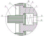
Fig. 2 is a front sectional view of the present invention.
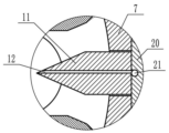
FIG. 3 is an enlarged view of A in FIG. 2 according to the present invention.
Fig. 4 is a top cross-sectional view of the present invention with the housing removed.
FIG. 5 is an enlarged view of B of FIG. 4 according to the present invention.
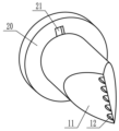
FIG. 6 is a perspective view of the slide bar and slide block of the present invention.
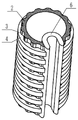
Fig. 7 is a perspective view of a filter cartridge, C-block and U-plate of the present invention.
Detailed Description
The following description of the embodiments of the present invention will be made in detail with reference to the accompanying drawings.
As shown in fig. 1 to 7, the filter cartridge comprises a housing 1, wherein the housing 1 is a cylindrical housing, a cylindrical filter cartridge 2 with a vertical axis is arranged in a cavity of the housing 1, the right end of the filter cartridge 2 is open, a plurality of grooves 3 in the vertical direction are formed in the outer edge surface of the filter cartridge 2, the grooves 3 are in arc transition with the outer edge surface of the filter cartridge 2, a plurality of C-shaped blocks 4 with opening directions consistent with that of the filter cartridge 2 are fixed on the outer edge surface of the filter cartridge 2 from top to bottom, the outer diameters of the C-shaped blocks 4 are larger than that of the filter cartridge 2 and are arranged at intervals, and a U-shaped plate 5 with an opening facing right is fixed at the opening position of the right end of the filter cartridge 2;
an annular rotary table 6 is fixed at the upper end and the lower end of the filter cylinder 2 respectively, the rotary table 6 is coaxial with the filter cylinder 2 and is rotatably connected with the outer edge surface of the filter cylinder 2, an arc-shaped plate 7 is fixed between the two rotary tables 6, the arc-shaped plate 7 is coaxial with the filter cylinder 2, when the arc-shaped plate 7 rotates to the right side of the filter cylinder 2 along with the rotary tables 6, the arc-shaped plate 7 can block the right side opening of the U-shaped plate 5, a plurality of chambers 8 are arranged from top to bottom on the inner edge surface of the arc-shaped plate 7, each chamber 8 is positioned at the interval position of each adjacent C-shaped block 4, a sliding rod 11 is arranged in each chamber 8, the left end of each sliding rod 11 penetrates through the inner edge surface of the arc-shaped plate 7 and can slide left and right in the chamber 8, the inner side end of each sliding rod 11 is flatly full of the C-shaped block 4 and is always attached to the outer edge surface of the filter cylinder 2, a first air pipe 12 in the horizontal direction is arranged in each sliding rod 11, and the first air pipe 12 can suck air to the inner side end of the sliding rod 11 when the sliding rod 11 moves outwards and blow air when the sliding rod 11 moves inwards;
an air outlet pipe 13 is fixed in the middle of the lower end face of the filter cylinder 2, the air outlet pipe 13 penetrates through the filter cylinder 2 and the lower end face of the shell 1, a through hole 14 is formed in the inner side area of the U-shaped plate 4 on the upper end face and the lower end face of the filter cylinder 2 respectively, the lower side through hole 14 is closed all the time under the condition of not being subjected to external force, and when the arc-shaped plate 7 rotates to the right side of the filter cylinder 2 along with the rotary table 2, the lower end through hole 14 is opened.
The motor 9 is fixed on the lower end face of the shell 1, an output shaft of the motor 9 penetrates into a cavity of the shell 1 and is respectively connected with the upper end face and the lower end face of the shell 1 in a rotating mode, an upper gear 10 and a lower gear 10 are fixedly connected onto the output shaft of the motor 9, outer edge faces of the two rotating discs 6 are tooth-shaped faces and are respectively meshed with the gears 10 on the upper side and the lower side, and the motor 9 can drive the rotating discs 6 to rotate.
The first through hole 14 at the upper end is connected with an air inlet pipe 15, the lower end of the through hole 14 at the lower end is connected with an exhaust pipe 16, a cloth bag 17 is fixed at the lower end of the exhaust pipe 16, the exhaust pipe 16 is a rectangular pipe, a baffle 18 is hinged to the inner wall of the pipe, the baffle 18 can swing up and down along a hinged point, the exhaust pipe 16 can be blocked when the baffle 18 is in a horizontal position, a torsion spring is fixed at the hinged position of the baffle 18, and the torsion spring always enables the baffle 18 to be in the horizontal position to block the exhaust pipe 16.
The first air pipe 12 is only communicated with one end face, close to the advancing direction, of the flat inner side end of the sliding rod 11, and therefore air blowing and air suction of the inner side end of the first air pipe 12 are guaranteed to be carried out only on one side in the scraping direction.
The filter cartridge 2 has a certain thickness, and the grooves 3 do not penetrate through the inner end surface and the outer end surface of the filter cartridge 2.
The C-shaped blocks 4 are arranged at equal intervals, and the sliding rods 11 are in clearance fit with the adjacent C-shaped blocks 5.
When the invention is used, firstly, the air is blown to the upper part of the working cavity of the cotton cleaner or the cotton carding machine by the fan, the air inlet pipe 15 is communicated with the working cavity of the cotton cleaner or the cotton carding machine, the air flow carries dust and cotton wool to enter the cavity of the shell 1 by the air pipe 15, then the clean air filtered by the filter cartridge 2 is discharged out of the shell 1 by the air outlet pipe 13 at the lower part, the motor 9 is started, the motor 9 drives the turntable 6 to rotate by the gear 10, the turntable 6 drives the arc-shaped plate 7 to be attached to the outer edge surface of the C-shaped block 4 to rotate, the inner side end of the slide bar 11 always receives the pressure of the pressure spring to be attached to the outer edge surface of the filter cartridge 2 to scrape materials, in the process that the slide bar 11 rotates along with the arc-shaped plate 8, because the outer edge surface of the filter cartridge 2 is uneven under the influence of the groove 3, the slide bar 11 and the slide block 20 can continuously slide in the cavity 8, and the slide block 20 moves a certain distance along the cavity 8 each time, because the second air pipe 21 is communicated with the first air pipe 12, the upper end and the lower end of the second air pipe 21 are respectively communicated with one end face, close to the sliding rod 11, of the sliding block 20, the sliding block 20 can compress air in the cavity 8 at one end of the inner side of the sliding block 20 to be discharged along the first air pipe 12 or expand the cavity 8 to enable the air to be sucked along the first air pipe 12, the air suction and the air discharge of the first air pipe 12 can blow and suck cotton wool, attached to the surface of the filter cartridge 2, in the front direction of the advancing direction of the sliding rod 11, the cotton wool is prevented from being tightly attached to the filter cartridge 2 and being inconvenient to scrape the sliding rod 11, and the sliding rod 11 is prevented from moving to the innermost side of the cavity 8 until the arc-shaped plate 7 moves to the opening position at the right side of the filter cartridge 2, because the filter cartridge 2 does not block the inner side of the sliding rod 11, the sliding rod 11 and the sliding block 20 rapidly move to the innermost side of the cavity 8 under the action of the compression spring, the air is discharged along the inner side of the first air along the inner side of the cavity 8 in the sliding block 20 in the moving process, the sliding rod 11 is blown to the space at the inner side of the U-shaped plate, meanwhile, because the arc plate 7 plugs the right opening of the U-shaped plate 5, the air inlet pipe 15 continues to supply air to the inner side of the U-shaped plate 5, so that the cavity in the inner side of the U-shaped plate 5 is positively pressurized, the torsion of a torsion spring of a hinge point of the baffle plate 18 is overcome to enable the baffle plate 18 to swing downwards to open the exhaust pipe 16, air flow enters the inner side of the U-shaped plate 5 through the air inlet pipe 15 and carries away cotton wool scraped by the inner side end of each sliding rod 11 and discharges the cotton wool into the cloth bag 17 through the exhaust pipe 16 at the lower end, then the arc plate 7 and the sliding rods 11 continue to rotate along with the turntable 6, the sliding rods 11 restart a new round of scraping, and finally the cotton wool collected in the cloth bag 17 can be taken out for unified recovery processing through the air flow.
According to the invention, the groove 3 and the fixed C-shaped block 4 are arranged on the outer edge surface of the filter cylinder 2, so that the outer edge surface of the filter cylinder 2 presents a longitudinal and circumferential concave-convex curved surface, cotton wool blocked outside the filter screen cannot be attached to the outer edge surface of the filter cylinder 2, and the sliding rod 11 can more easily scrape the cotton wool outside the filter cylinder 2; the inner end of the sliding rod 11 is always attached to the outer edge surface of the filter cylinder 2 to scrape materials under the pressure of the pressure spring, the sliding rod 11 generates displacement in the radial direction of the filter cylinder 2 in the rotating process along with the arc-shaped plate 7 under the influence of the groove 3, the sliding block 20 is matched with the cavity 8 to form a cylinder, the inner end of the sliding rod 11 is continuously blown and sucked through the first air pipe 12, cotton wool attached to the surface of the filter cylinder 2 in the front of the advancing direction of the sliding rod 11 can be blown and sucked, the phenomenon that the cotton wool is tightly attached to the filter cylinder 2 and is not convenient for the sliding rod 11 to scrape is avoided, the self-cleaning effect of the filter cylinder 3 is greatly improved, the integral filtering efficiency of the device is improved, and the service life of the device is prolonged;
according to the invention, the U-shaped plate 5 is arranged at the opening position on the right side of the filter cartridge 2, so that the arc-shaped plate 7 blocks the opening on the right side of the filter cartridge 2 when rotating to the position of the U-shaped plate 5 along with the rotary disc 6, and simultaneously forms a closed cavity together with the U-shaped plate 5, the airflow entering from the air inlet pipe 15 can be discharged outwards only through the exhaust pipe 16, cotton wool scraped to the inner side of the U-shaped plate 5 by the slide rod 11 can be flushed out into the cloth bag 17 by the airflow, the centralized collection of the cotton wool scraped by the slide rod 11 is realized, and when the arc-shaped plate 7 leaves the position of the U-shaped plate 5, the baffle 18 restores to the horizontal position under the torsion action of the torsion spring to block the exhaust pipe 16 again, so that the collected cotton wool is prevented from being returned again.
Claims (7)
1. The textile cotton wool filtering device comprises a shell (1) and is characterized in that the shell (1) is a cylindrical shell, a cylindrical filter cylinder (2) with an axis vertically arranged is arranged in a cavity of the shell (1), the right end of the filter cylinder (2) is provided with an opening, the outer edge surface of the filter cylinder (2) is provided with a plurality of grooves (3) in the vertical direction, the grooves (3) and the outer edge surface of the filter cylinder (2) are in circular arc transition, a plurality of C-shaped blocks (4) with opening directions consistent with those of the filter cylinder (2) are fixed on the outer edge surface of the filter cylinder (2) from top to bottom, the outer diameter of each C-shaped block (4) is larger than the outer diameter of the filter cylinder (2) and is arranged at intervals, and a U-shaped plate (5) with an opening facing right is fixed at the opening position of the right end of the filter cylinder (2);
an annular turntable (6) is fixed at each of the upper end and the lower end of the filter cylinder (2), the turntable (6) is coaxial with the filter cylinder (2) and is rotatably connected with the outer edge surface of the filter cylinder (2), an arc-shaped plate (7) is fixed between the two turntables (6), the arc-shaped plate (7) is coaxial with the filter cylinder (2), when the arc-shaped plate (7) rotates to the right side of the filter cylinder (2) along with the turntable (6), the arc-shaped plate (7) can block an opening at the right side of the U-shaped plate (5), a plurality of chambers (8) are arranged on the inner edge surface of the arc-shaped plate (7) from top to bottom, each chamber (8) is located at the interval position of each adjacent C-shaped block (4), a sliding rod (11) is arranged in each chamber (8), the left end of each sliding rod (11) penetrates through the inner edge surface of the arc-shaped plate (7) and can slide in each chamber (8), the inner edge surface of each chamber (8), the inner side end of each sliding rod (11) is flatly covered with the C-shaped blocks (4) at intervals and can always cling to the outer edge surface of the filter cylinder (2), a first air pipe (12) is arranged in each sliding rod (11), and the inner side end of each sliding rod (11) can move towards the outer side when the sliding rod (11) moves towards the sliding rod (11), and the inner side of the sliding rod (11) in the sliding rod (12) in the sliding rod (11);
the middle part of the lower end face of the filter cylinder (2) is fixed with an air outlet pipe (13), the air outlet pipe (13) penetrates through the lower end faces of the filter cylinder (2) and the shell (1), the inner side areas of the U-shaped plate (4) on the upper end face and the lower end face of the filter cylinder (2) are respectively provided with a through hole (14), the lower side through hole (14) is closed all the time under the condition of not receiving external force, and when the arc-shaped plate (7) rotates along with the rotary disc (2) to the right side of the filter cylinder (2), the lower end through hole (14) is opened.
2. The textile batt filter device according to claim 1, wherein a motor (9) is fixed on the lower end surface of the housing (11), an output shaft of the motor (9) penetrates into the cavity of the housing (1) and is respectively connected with the upper end surface and the lower end surface of the housing (1) in a rotating manner, an upper gear (10) and a lower gear (10) are fixedly connected on the output shaft of the motor (9), and the outer edge surfaces of the two rotating discs (6) are tooth-shaped surfaces and are respectively meshed with the gears (10) on the upper side and the lower side.
3. The textile batting filter device according to claim 1, wherein an air inlet pipe (15) is connected to the first through hole (14) at the upper end, an exhaust pipe (16) is connected to the lower end of the through hole (14) at the lower end, a cloth bag (17) is fixed to the lower end of the exhaust pipe (16), the exhaust pipe (16) is a rectangular pipe, a baffle (18) is hinged to the inner wall of the rectangular pipe, the baffle (18) can swing up and down along the hinged point, the exhaust pipe (16) can be blocked when the baffle (18) is in the horizontal position, a torsion spring is fixed to the hinged position of the baffle (18), and the torsion spring always enables the baffle (18) to be in the horizontal position.
4. The textile cotton wool filtering device according to claim 1, wherein round holes (19) communicated with the inner end face and the outer end face of the arc-shaped plate (7) are formed in the left side and the right side of each chamber (8) respectively, a sliding block (20) is fixed to the portion, located in the chamber (8), of the outer end of each sliding rod (11), the sliding block (20) can horizontally slide left and right along the chamber (8), the outer edge face of the sliding block (20) is always attached to the chamber (8), a pressure spring is fixed between the sliding block (20) and the outer end face of the chamber (8), a second air pipe (21) in the vertical direction is formed in each sliding block (20), the second air pipe (21) is communicated with the first air pipe (12), and the upper end and the lower end of the second air pipe (21) are communicated with one end face, close to the sliding rod (11), of the sliding block (20) respectively.
5. A textile batt filter device according to claim 1, wherein the first air duct (12) communicates only with one end of the slide bar (11) at its flat inner end in the forward direction, ensuring that blowing and suction at the inner end of the first air duct (12) are performed only on one side in the direction of scraping.
6. A textile batt filtration device according to claim 1, wherein the filter cartridge (2) has a thickness such that the grooves (3) do not extend through the inner and outer end surfaces of the filter cartridge (2).
7. A textile batt filtration device according to claim 1, wherein the C-shaped blocks (4) are equally spaced and the slide bars (11) are in clearance fit with adjacent C-shaped blocks (5).
Priority Applications (1)
| Application Number | Priority Date | Filing Date | Title |
|---|---|---|---|
| CN202310012579.2A CN115738531A (en) | 2023-01-05 | 2023-01-05 | Textile cotton fiber filtering device |
Applications Claiming Priority (1)
| Application Number | Priority Date | Filing Date | Title |
|---|---|---|---|
| CN202310012579.2A CN115738531A (en) | 2023-01-05 | 2023-01-05 | Textile cotton fiber filtering device |
Publications (1)
| Publication Number | Publication Date |
|---|---|
| CN115738531A true CN115738531A (en) | 2023-03-07 |
Family
ID=85348191
Family Applications (1)
| Application Number | Title | Priority Date | Filing Date |
|---|---|---|---|
| CN202310012579.2A Withdrawn CN115738531A (en) | 2023-01-05 | 2023-01-05 | Textile cotton fiber filtering device |
Country Status (1)
| Country | Link |
|---|---|
| CN (1) | CN115738531A (en) |
Cited By (1)
| Publication number | Priority date | Publication date | Assignee | Title |
|---|---|---|---|---|
| CN116328446A (en) * | 2023-03-30 | 2023-06-27 | 北京中科辉丰科技有限公司 | Low-temperature flue gas desulfurization equipment of sintering machine |
-
2023
- 2023-01-05 CN CN202310012579.2A patent/CN115738531A/en not_active Withdrawn
Cited By (1)
| Publication number | Priority date | Publication date | Assignee | Title |
|---|---|---|---|---|
| CN116328446A (en) * | 2023-03-30 | 2023-06-27 | 北京中科辉丰科技有限公司 | Low-temperature flue gas desulfurization equipment of sintering machine |
Similar Documents
| Publication | Publication Date | Title |
|---|---|---|
| CN210751690U (en) | Non-woven fabric production facility exhaust treatment device | |
| CN115738531A (en) | Textile cotton fiber filtering device | |
| CN108815968A (en) | A kind of device of workshop good dedusting effect | |
| CN110200547B (en) | Dust removal structure with metal mesh filtering structure | |
| CN115814544A (en) | Cotton fibre filtering and collecting device of cotton cleaner | |
| CN211963412U (en) | Bag type dust collector | |
| CN218358049U (en) | Assembly table with dust removal function | |
| CN218166277U (en) | Self-cleaning pulse type bag dust collector | |
| CN217724991U (en) | Dust collecting equipment for flour workshop | |
| CN113246024B (en) | High-frequency vibration polishing and dedusting equipment | |
| CN216653768U (en) | Auxiliary assembly for automatic multi-directional dust removal before spraying for electric vehicle accessories | |
| CN213555942U (en) | Knitting workshop dust treatment device with two-stage dust removal mechanism | |
| CN215148159U (en) | High-frequency vibration dust collecting equipment that polishes | |
| CN115245714A (en) | Dust filter equipment is used in weaving workshop | |
| CN214680729U (en) | Dust removal filter of central dust removal system | |
| CN211097990U (en) | Dust collector that honeycomb curtain workshop was used | |
| CN210529187U (en) | Circular knitting machine hair removal edulcoration device is used in knitted fabric production | |
| CN209885426U (en) | High-efficient bag collector | |
| CN219290889U (en) | Dust collecting equipment with deashing function | |
| CN219401234U (en) | Cotton wool collecting device for spinning workshop | |
| CN220013089U (en) | Dust collector of surface fabric napping machine | |
| CN220530982U (en) | Filter bag type dust remover | |
| CN219342472U (en) | Grid arrangement device | |
| CN212188292U (en) | Filter cartridge dust remover | |
| CN217220648U (en) | Workshop dust removal device for cotton yarn production |
Legal Events
| Date | Code | Title | Description |
|---|---|---|---|
| PB01 | Publication | ||
| PB01 | Publication | ||
| SE01 | Entry into force of request for substantive examination | ||
| SE01 | Entry into force of request for substantive examination | ||
| WW01 | Invention patent application withdrawn after publication | ||
| WW01 | Invention patent application withdrawn after publication |
Application publication date: 20230307 |