CN1157088C - Multifunctional music centre apparatus - Google Patents
Multifunctional music centre apparatus Download PDFInfo
- Publication number
- CN1157088C CN1157088C CNB01143757XA CN01143757A CN1157088C CN 1157088 C CN1157088 C CN 1157088C CN B01143757X A CNB01143757X A CN B01143757XA CN 01143757 A CN01143757 A CN 01143757A CN 1157088 C CN1157088 C CN 1157088C
- Authority
- CN
- China
- Prior art keywords
- rotor
- loud speaker
- stator
- voice coil
- permanent magnet
- Prior art date
- Legal status (The legal status is an assumption and is not a legal conclusion. Google has not performed a legal analysis and makes no representation as to the accuracy of the status listed.)
- Expired - Fee Related
Links
Images


Classifications
-
- H—ELECTRICITY
- H04—ELECTRIC COMMUNICATION TECHNIQUE
- H04R—LOUDSPEAKERS, MICROPHONES, GRAMOPHONE PICK-UPS OR LIKE ACOUSTIC ELECTROMECHANICAL TRANSDUCERS; DEAF-AID SETS; PUBLIC ADDRESS SYSTEMS
- H04R9/00—Transducers of moving-coil, moving-strip, or moving-wire type
- H04R9/02—Details
-
- H—ELECTRICITY
- H04—ELECTRIC COMMUNICATION TECHNIQUE
- H04R—LOUDSPEAKERS, MICROPHONES, GRAMOPHONE PICK-UPS OR LIKE ACOUSTIC ELECTROMECHANICAL TRANSDUCERS; DEAF-AID SETS; PUBLIC ADDRESS SYSTEMS
- H04R9/00—Transducers of moving-coil, moving-strip, or moving-wire type
- H04R9/06—Loudspeakers
-
- H—ELECTRICITY
- H04—ELECTRIC COMMUNICATION TECHNIQUE
- H04R—LOUDSPEAKERS, MICROPHONES, GRAMOPHONE PICK-UPS OR LIKE ACOUSTIC ELECTROMECHANICAL TRANSDUCERS; DEAF-AID SETS; PUBLIC ADDRESS SYSTEMS
- H04R2400/00—Loudspeakers
- H04R2400/03—Transducers capable of generating both sound as well as tactile vibration, e.g. as used in cellular phones
Abstract
A speaker diaphragm having a voice coil secured thereto is provided in a frame, a rotor having a permanent magnet is rotatably supported in the frame, and a stator having poles is provided in the frame. The permanent magnet provided on the rotor is provided for forming a magnetic circuit passing through the rotor and the stator, and a stator coil is provided in the stator. A driving circuit is provided for energizing the stator coil for rotating the rotor.
Description
Technical field
The present invention relates to a kind of in portable set the multifunctional music centre apparatus that uses of portable phone for example.
Background technology
In the acoustics of the portable set that is now provided, the loud speaker that is provided is to be used for producing call signal sound, and the vibrating motor that provides is used under not sonorific situation, informs that the recipient has call signal.In this device,, device size and weight and manufacturing cost have just been increased because loud speaker and motor all are placed in the acoustics.
In recent years, in order to eliminate above-mentioned defective, a kind of multifunctional music centre apparatus is proposed.This multifunctional music centre apparatus comprise have lamina membranacea be placed in the loud speaker lamina membranacea on the loud speaker of the permanent magnet that links to each other of voice coil loudspeaker voice coil magnetic.Therefore permanent magnet independently vibrates at the low frequency of 100-150Hz, is sent to the device users health by the vibration of crust of the device and informs and receive call signal.
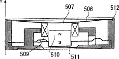
Fig. 6 is the sectional view of the traditional electrical magnetic induction transducer that discloses in Japanese utility model application publication number 5-85192.This transducer comprises the lamina membranacea 506, the voice coil loudspeaker voice coil 509 that is fixed on lamina membranacea 506 middle body downsides that are placed in shell 512 peripheries, is placed in the latch plate 511 in the shell 512 and is fixed on latch plate 511 middle bodies, is inserted in the permanent magnet 510 in the voice coil loudspeaker voice coil 509.
By apply low frequency or high-frequency signal on voice coil loudspeaker voice coil 509, latch plate 511 just can vibrate on the polar orientation Y of magnet 510.
In equipment, lamina membranacea 506 and latch plate 511 by the magnetic between voice coil loudspeaker voice coil 509 and magnet 510 in conjunction with relative motion.Thereby when applying low frequency signal or high-frequency signal on voice coil loudspeaker voice coil 509, lamina membranacea 506 and latch plate 511 all can vibrate in succession.Therefore, just make the sound that from device, generates for example voice, music and other audio distortions, therefore reduced tonequality.In addition, in the time of voice coil loudspeaker voice coil 509 and magnet 510 vibration cause the magnetic of voice coil loudspeaker voice coil 509 and magnet 510 in conjunction with on the superposeed low-frequency vibration of magnet, this has just further increased the distortion of sound.
Fig. 7 is the sectional view at a kind of traditional multifunctional music centre apparatus shown in the Japanese patent application publication No. 2001-225010.This device comprises the loud speaker lamina membranacea 603 that is made of plastics and has peripheral 603a of waveform and center dome, is fixed on the voice coil loudspeaker voice coil 604 of lamina membranacea 603 middle body downsides, and magnet loomplex 61 0.Lamina membranacea 603 usefulness adhesive are on framework 609.
Magnet loomplex 61 0 comprises following yoke 605, at magnetic core 601 that yoke 605 middle bodies form, be placed in the annular permanent magnnet 602 on the yoke 605 down and be placed in yoke 606 on the annular on the permanent magnet 602.In framework 609, following yoke 605 and last yoke 606 provide resiliency supported by latch plate 607 and 608.The magnetic gap 611 that forms between the inwall 606a of 601 peripheral 601a unshakable in one's determination and last yoke 606 will link to each other with voice coil loudspeaker voice coil 604 magnetic.
When by input 612a and 612b when voice coil loudspeaker voice coil 604 applies alternating voltage, loud speaker lamina membranacea 603 just vibrates on direction Y, the sound of generated frequency between 700Hz and 5KHz.If apply low frequency signal or high-frequency signal to voice coil loudspeaker voice coil 604, the just vibration in succession of loud speaker lamina membranacea 603 and magnet loomplex 61 0 is because the relative motion by the magnetic combination of voice coil loudspeaker voice coil 604 and magnet loomplex 61 0 of magnet loomplex 61 0 and loud speaker lamina membranacea 603.
Therefore, just make the sound that from device, generates for example voice, music and other audio distortions, thereby reduced tonequality.In addition, in the time of voice coil loudspeaker voice coil 604 and magnet loomplex 61 0 vibration cause the magnetic of voice coil loudspeaker voice coil 604 and magnet loomplex 61 0 in conjunction with on the low-frequency vibration that superposeed, this has just further increased the distortion of sound.
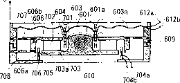
Fig. 8 is the sectional view of another kind of traditional multifunctional music centre apparatus of disclosing in Japanese patent application publication No. 2001-300422.This device comprises the loud speaker lamina membranacea 603 with the peripheral 603a of waveform and center dome that plastics are made, and is fixed on the voice coil loudspeaker voice coil 604 of lamina membranacea 603 middle body downsides, and magnet loomplex 61 0.Lamina membranacea 603 usefulness adhesive are on framework 609.
Magnet loomplex 61 0 comprises following yoke 703, the magnetic core 601 that forms on yoke 703 middle bodies down, be fixed on the annular permanent magnnet 702 on the yoke 703 down, and is placed on yoke 606 on the annular that has sidewall 606b on every side on the permanent magnet 702.Last yoke 606 obtains resiliency supported by latch plate 707 and 708 in framework 609.Between the inwall 606a of the peripheral 601a of magnetic core 601 and last yoke 606, form first magnetic gap 701, be connected with voice coil loudspeaker voice coil 604 magnetic.Between the inwall 606a of peripheral 703a that descends yoke 703 and last yoke 606, form second magnetic gap 705.Drive coil 706 is fixed on the framework, and inserts in second magnetic gap 705.
When alternating voltage was applied on the voice coil loudspeaker voice coil 604 by input 612a and 612b, loud speaker lamina membranacea 603 was along Y direction vibration, produce frequency at 700Hz to the sound between the 5KHz.If low frequency signal or high-frequency signal are applied on the voice coil loudspeaker voice coil 604, because magnet loomplex 61 0 and loud speaker lamina membranacea 603 carry out relative motion by the magnetic combination of voice coil loudspeaker voice coil 604 and magnet loomplex 61 0, so loud speaker lamina membranacea 603 and magnet loomplex 61 0 vibrate in succession.
When the high-frequency signal as music is applied on the voice coil loudspeaker voice coil 604,603 vibrations of loud speaker lamina membranacea are only arranged.Thereby, there is not sonorific distortion.And, when low frequency signal is applied on the drive coil 706,0 vibration of magnet loomplex 61 is only arranged, and not vibration of loud speaker lamina membranacea 603.
Yet, if what apply at input 612a, 612b is high-frequency signal, and also applying low frequency signal at input 704a, 704b, loud speaker lamina membranacea 603 and magnet loomplex 61 0 will vibrate in succession, thereby have reduced the quality of sound.
In the conventional apparatus of above-mentioned discussion, when apply low frequency signal or high-frequency signal on voice coil loudspeaker voice coil, loud speaker lamina membranacea and magnet compound all can vibrate in succession.This is because cause identical with the dither direction of direction of vibration of low-frequency vibration compound.
Summary of the invention
One object of the present invention is to provide a kind of multifunctional music centre apparatus, and the vibrating elements of portion can not vibrate with the vibration of another one vibrating elements within it, thereby has eliminated the defective of conventional apparatus.
According to the present invention, a kind of multifunctional music centre apparatus that provides comprises framework, by the loud speaker lamina membranacea of frame supported, be fixed on voice coil loudspeaker voice coil, rotor that rotatably support by framework and that have the ring-shaped rotor permanent magnet on the loud speaker lamina membranacea, be configured in the stator that has magnetic pole in the framework, corresponding with rotor, as to be used between the rotor permanent magnet of rotor and magnetic pole of the stator, forming magnetic flux stator coil.
This device further comprise the middle body bottom that is fixed in the framework cylindrical loud speaker yoke, be fixed in the loud speaker permanent magnet of loud speaker yoke bottom and be fixed on loud speaker permanent magnet top top board, be configured in the eccentric that is used for vibrating rotator during the rotor rotation on the rotor.
Be placed on the voice coil loudspeaker voice coil in the formed gap between loud speaker yoke and the top board.
The rotor permanent magnet that rotatably supports by loud speaker yoke peripheral outer wall.
Eccentric is that off-centre is placed on epitrochanterian pouring weight.
Be used for coil to stator the excitatory drive circuit that comes rotor is provided.
These and some other purpose of the present invention and feature will be below become more obvious in conjunction with the accompanying drawings the detailed description.
Description of drawings
Fig. 1 is the sectional view of multifunctional music centre apparatus of the present invention;
Fig. 2 is the sectional view along II-II line among Fig. 1;
Fig. 3 is the rotor decomposition diagram of multifunctional music centre apparatus of the present invention;
Fig. 4 is the stator decomposition diagram of multifunctional music centre apparatus of the present invention;
Fig. 5 is an employed drive circuit in the multifunctional music centre apparatus of the present invention;
Fig. 6 is a kind of sectional view of traditional electromagnetic induction transducer;
Fig. 7 illustrates a kind of sectional view of traditional multifunctional music centre apparatus;
Fig. 8 illustrates the sectional view of the traditional multifunctional music centre apparatus of another kind.
Embodiment
See figures.1.and.2, multifunctional music centre apparatus of the present invention comprises sound generator spare 10, rotor 20 and is configured in annular stator 30 in the plastics cylindricality framework 1.Sound generator spare 10 comprise have center dome 14a and at peripheral 14b place with the loud speaker lamina membranacea 14 of adhesive on framework, be fixed on the voice coil loudspeaker voice coil 15 of loud speaker lamina membranacea 14 downsides.Loud speaker lamina membranacea 14 is had a plurality of sound discharge orifices and the emulsion sheet 13 that is fixed on the framework 1 at its external boundary place covers.
The cylindrical loud speaker yoke of being made by magnetic material 21 is fixed on the middle body of the substrate of framework 1, and is fixed on the bottom of loud speaker yoke 21 along the magnetized cylindrical loud speaker permanent magnet 22 of axis direction.The top yoke of being made by magnetic material 23 is fixed on the top of permanent magnet 22.Voice coil loudspeaker voice coil 15 is placed in the loud speaker gap 11 that forms between the inwall of the outer wall of top yoke 23 and loud speaker yoke 21.
Rotor 20 comprises by annular end thrust ball bearing 25 and cylindrical end thrust ball bearing 26 and rotatably is placed on ring-shaped rotor permanent magnet 24 on framework 1 substrate and loud speaker yoke 21 outer walls that annular permanent magnnet 24 radially is being magnetized.
Semicircle pouring weight 27 (Fig. 2) is placed on the permanent magnet 24 safely.As another kind of device, permanent magnet 24 can come eccentric the placement with respect to the axle of rotor 20.As shown in figs. 1 and 2, annular stator 30 surrounding rotors 20 are placed, and therefore, form second gap 12 between the periphery of rotor 20 and annular stator 30 inwalls.
With reference to Fig. 4, stator 30 comprises annular stator coil 33, be placed on the annular of loop coil 33 upsides and downside barricade 36 and following barricade 35 and annular goes up stator yoke 31 and annular stator yoke 32 down.Last stator yoke 31 has 4 main pole 31a1,31b1,31c1 and 31d1, and 4 auxiliary magnetic pole 31a2,31b2,31c2 and 31d2.Each magnetic pole is stator yoke 32 extensions downwards vertically.Following stator yoke 32 has 4 main pole 32a1,32b1,32c1 and 32d1, and 4 auxiliary magnetic pole 32a2,32b2,32c2 and 32d2.
A pair of upward main pole and auxiliary magnetic pole 31a1 and 31a2 and a pair of main pole and auxiliary magnetic pole 32a1 and 32a2 down, and other pole pairs are positioned in the scope that distance between two poles is 90 degree (electrical degree is 360 °) angledly.The width summation of main pole and auxiliary magnetic pole is within 45 degree, and the width of main pole is greater than the width of auxiliary magnetic pole.
A pair ofly go up main pole and auxiliary magnetic pole and a pair of down main pole is alternate as shown in Figure 2 with auxiliary magnetic pole is placed on the same ring.
Last barricade 36 has 4 hole 36a, 36b, 36c and 36d, and each hole all is inwardly radially to protrude from barricade 36 inboards to form projection.Similarly, following barricade 35 has 4 hole 35a, 35b, 35c and 35d.Auxiliary magnetic pole 31a2,31b2,31c2 and the 31d2 of last stator yoke 31 is inserted among the hole 36a-36d of barricade 36.Similarly, auxiliary magnetic pole 32a2,32b2,32c2 and the 32d2 of following stator yoke 32 are inserted into down among the hole 35a-35d of barricade 35.
With reference to Fig. 1 and 4, following stator yoke 32 has cylindricality outer wall 32e.Following barricade 35 is placed on the following stator yoke 32 between outer wall 32e and master and the auxiliary magnetic pole.Stator coil 33, last barricade 36 and last stator yoke 31 sequential cascades are on following barricade 35.Thereby rotor 20 and stator 30 formation synchronous machines.
Be understandable that motor can make the stepping motor with multipolar permanent magnet.
The magnetomotive force of permanent magnet 24 imposes on second gap 12, therefore provides necessary magnetic density for rotor.
With reference to Fig. 5, rotor driven circuit 40 comprises interconnection, inserts a pair of NPN transistor 41 and 43 and a pair of PNP transistor 42 and 44 of stator coil 33. Transistor 41 and 42 base stage are connected input 48, and transistor 43 and 44 base stage are connected input 48 by phase inverter 47.
In when running, when to the input 19a of voice coil loudspeaker voice coil 15 and 19b (Fig. 1) when applying high-frequency signal, loud speaker lamina membranacea 14 is just along the vibration of Y direction, generation sound.
When the input 48 to drive circuit 40 applies the low frequency signal of about 100-300Hz, transistor 41 and 44 conductings when input signal is high level.Thereby the electric current from Vcc to GND has flow through stator coil 33 by transistor 41 and 44.And electric current flows through transistor 43, coil 33 and transistor 42 when the input signal low level.And flow into stator coil 33 corresponding to the low-frequency ac electric current of input low frequency signal.Thereby, to main pole 32a1 and interpole 32a2 extremely to extremely carrying out excitatory to 32d1 and 32d2.Simultaneously, by the magnetic flux that generates among 4 interpole 31a2,31b2,31c2 and the 31d2 and by the magnetic flux that generates among 4 interpole 32a2,32b2,32c2 and the 32d2, by hole 36a-36d that passes barricade 36 and the following vortex flow phase retardation of the hole 35a-35d of barricade 35, produce the shifting magnetic field, thereby generate rotating energy at predetermined direction.Like this, rotor 20 rotates to drive low frequency.Because pouring weight 27 off-centre are placed on the rotor 20, so rotor vibrates diametrically.Vibration is sent to user's body by the framework 1 and the shell of device, therefore, just notifies the user that call signal is arranged.
The rotational speed N of rotor is expressed as follows:
N=60f/Z(rpm) 1
Wherein Z is the number of pole-pairs of rotor,
F is a driving frequency.
Load torque TL is expressed as follows:
TL=μrRω
2M(N·m) 2
Wherein M is the quality of rotor pouring weight 27,
R is the length between rotor center and pouring weight 27 centers of gravity,
R is a rotor radius,
μ is the coefficient of friction between rotor and the loud speaker yoke 21,
ω is the revolution (rad/sec) of rotor 20.
Because rotor 20 is only born load torque TL, so the power consumption of device is very little.
If during generating sound, apply low frequency signal to input 48 and come magnetic densities in rotor 20, the first gaps 11 can be same as magnetic density when 14 vibrations of loud speaker lamina membranacea are only arranged by loud speaker lamina membranacea 14.
Though use synchronous machine in the above-described embodiments, other motor for example stepping motor, direct current machine and other motor can use.Further, rotor can be placed on the outside of stator.
From aforementioned, can understand the invention provides and a kind ofly can produce sound equipment and structural vibration simultaneously and can not reduce the multifunctional music centre apparatus of tonequality.In prior art,, increased the thickness of device because loud speaker lamina membranacea and magnet compound vibrate at equidirectional.In the device in the present invention, because the rotation of magnet compound, so the thickness of device is reduced.
Though the present invention is by being described in conjunction with preferable explanation embodiment, it must be appreciated that these purpose of description are that explanation rather than qualification are by the defined category of the present invention of following claim.
Claims (8)
1, a kind of multifunctional music centre apparatus is characterized in that, comprising:
Framework;
Be supported on the loud speaker lamina membranacea in the described framework;
Be fixed in the voice coil loudspeaker voice coil of described loud speaker lamina membranacea;
The rotor that has the ring-shaped rotor permanent magnet and rotatably support by described framework;
Have magnetic pole and place in the described framework, corresponding to the stator of described rotor;
Be used between the rotor permanent magnet of described rotor and magnetic pole of the stator, forming the stator coil of magnetic flux.
2, device as claimed in claim 1, it is characterized in that, further comprise the middle body bottom that is fixed on described framework cylindrical loud speaker yoke, be fixed in the loud speaker permanent magnet of described loud speaker yoke bottom and be fixed on the top board at described loud speaker permanent magnet top.
3, device as claimed in claim 1 is characterized in that, further comprises being configured in the eccentric that is used for vibrating rotator during the rotor rotation on the described rotor.
4, device as claimed in claim 2 is characterized in that, described coil is placed in the gap that forms between described loud speaker yoke and the top board.
5, device as claimed in claim 2 is characterized in that, described loud speaker yoke peripheral outer wall rotatably supports described rotor permanent magnet.
6, device as claimed in claim 3 is characterized in that, described eccentric is that off-centre is placed on the pouring weight in the described rotor.
7, device as claimed in claim 5 is characterized in that, further comprises the drive circuit that is used to coil in the excitatory described stator of rotating said rotor.
8, device as claimed in claim 7 is characterized in that, described rotor and stator form synchronous machine.
Applications Claiming Priority (3)
| Application Number | Priority Date | Filing Date | Title |
|---|---|---|---|
| JP384600/00 | 2000-12-19 | ||
| JP384600/2000 | 2000-12-19 | ||
| JP2000384600A JP2002186080A (en) | 2000-12-19 | 2000-12-19 | Multifunctional acoustic unit |
Publications (2)
| Publication Number | Publication Date |
|---|---|
| CN1360454A CN1360454A (en) | 2002-07-24 |
| CN1157088C true CN1157088C (en) | 2004-07-07 |
Family
ID=18852012
Family Applications (1)
| Application Number | Title | Priority Date | Filing Date |
|---|---|---|---|
| CNB01143757XA Expired - Fee Related CN1157088C (en) | 2000-12-19 | 2001-12-19 | Multifunctional music centre apparatus |
Country Status (6)
| Country | Link |
|---|---|
| US (1) | US6621911B2 (en) |
| EP (1) | EP1217872A3 (en) |
| JP (1) | JP2002186080A (en) |
| KR (1) | KR100452828B1 (en) |
| CN (1) | CN1157088C (en) |
| TW (1) | TW521534B (en) |
Cited By (1)
| Publication number | Priority date | Publication date | Assignee | Title |
|---|---|---|---|---|
| CN102440004A (en) * | 2009-04-22 | 2012-05-02 | 株式会社礼一电子 | Sensory signal output apparatus |
Families Citing this family (14)
| Publication number | Priority date | Publication date | Assignee | Title |
|---|---|---|---|---|
| US20050099255A1 (en) * | 2000-08-18 | 2005-05-12 | Fan Zhang | Transducer with dual coil and dual magnetic gap |
| JP2002095079A (en) * | 2000-09-12 | 2002-03-29 | Citizen Electronics Co Ltd | Multifunctional sound system |
| JP2002101495A (en) * | 2000-09-21 | 2002-04-05 | Citizen Electronics Co Ltd | Multi-function type acoustic device |
| US7473947B2 (en) * | 2002-07-12 | 2009-01-06 | Intel Corporation | Process for ultra-thin body SOI devices that incorporate EPI silicon tips and article made thereby |
| US20050139414A1 (en) * | 2003-12-30 | 2005-06-30 | Nicholas Edwin | Gyrating acoustical bearing brackets |
| KR100697838B1 (en) | 2006-02-03 | 2007-03-22 | 오홍균 | Vibratory moving apparatus |
| WO2007093903A1 (en) * | 2006-02-16 | 2007-08-23 | Bang & Olufsen Icepower A/S | A micro-transducer with improved perceived sound quality |
| KR101074830B1 (en) * | 2009-12-18 | 2011-10-19 | 주식회사 예일전자 | Sensory signal output apparatus |
| KR101184537B1 (en) * | 2010-03-09 | 2012-09-19 | 허동철 | Speaker |
| WO2011111968A2 (en) * | 2010-03-09 | 2011-09-15 | Kim Suk-Joo | Speaker |
| JP6325957B2 (en) | 2014-10-03 | 2018-05-16 | クラリオン株式会社 | Exciter |
| US9571936B2 (en) * | 2015-05-01 | 2017-02-14 | Apple Inc. | Audio speaker having a high-saturation magnetic insert |
| JP2018050141A (en) * | 2016-09-21 | 2018-03-29 | カシオ計算機株式会社 | Acoustic device |
| CN110049413A (en) * | 2019-05-10 | 2019-07-23 | 广东朝阳电子科技股份有限公司 | The vibration moving-coil compound horn of sound quality modified form double magnetic circuit double diaphragm |
Family Cites Families (17)
| Publication number | Priority date | Publication date | Assignee | Title |
|---|---|---|---|---|
| JPS61180558A (en) * | 1985-02-04 | 1986-08-13 | Fumito Komatsu | Dc motor |
| US4931765A (en) * | 1989-02-09 | 1990-06-05 | Motorola, Inc. | Unitized housing for silent and tone pager alerting system |
| JPH07106043B2 (en) * | 1990-05-08 | 1995-11-13 | ブラザー工業株式会社 | Motor stator structure |
| JPH08206599A (en) * | 1995-02-07 | 1996-08-13 | Seiko Instr Inc | Signal alarming device by vibration |
| JP3366507B2 (en) * | 1995-09-05 | 2003-01-14 | 松下電器産業株式会社 | Vibration generator |
| US5668423A (en) * | 1996-03-21 | 1997-09-16 | You; Dong-Ok | Exciter for generating vibration in a pager |
| JP3334842B2 (en) * | 1996-05-28 | 2002-10-15 | 東北パイオニア株式会社 | Speaker unit and manufacturing method thereof |
| JPH10285900A (en) * | 1997-04-01 | 1998-10-23 | Tokyo Parts Ind Co Ltd | Pulse motor |
| JP2000069587A (en) * | 1998-08-20 | 2000-03-03 | Sony Corp | Speaker |
| JP2000070856A (en) * | 1998-08-25 | 2000-03-07 | Shicoh Eng Co Ltd | Vibration motor |
| JP2000126938A (en) * | 1998-10-27 | 2000-05-09 | Sodick Co Ltd | Spindle device of discharge machine |
| KR20000040796A (en) * | 1998-12-19 | 2000-07-05 | 이형도 | Speaker apparatus having dual magnets |
| JP3166757B2 (en) * | 1999-02-24 | 2001-05-14 | 松下電器産業株式会社 | Brushless vibration motor |
| KR100354376B1 (en) * | 1999-12-08 | 2002-09-28 | 에스텍 주식회사 | Speaker having a device capable of generating both sound and vibration |
| KR20020006292A (en) * | 2000-07-12 | 2002-01-19 | 이형도 | Vibration speaker |
| JP2002095079A (en) * | 2000-09-12 | 2002-03-29 | Citizen Electronics Co Ltd | Multifunctional sound system |
| JP2002101495A (en) * | 2000-09-21 | 2002-04-05 | Citizen Electronics Co Ltd | Multi-function type acoustic device |
-
2000
- 2000-12-19 JP JP2000384600A patent/JP2002186080A/en active Pending
-
2001
- 2001-12-04 US US10/000,483 patent/US6621911B2/en not_active Expired - Fee Related
- 2001-12-11 TW TW090130617A patent/TW521534B/en not_active IP Right Cessation
- 2001-12-13 KR KR10-2001-0079048A patent/KR100452828B1/en not_active IP Right Cessation
- 2001-12-19 CN CNB01143757XA patent/CN1157088C/en not_active Expired - Fee Related
- 2001-12-19 EP EP01130322A patent/EP1217872A3/en not_active Withdrawn
Cited By (1)
| Publication number | Priority date | Publication date | Assignee | Title |
|---|---|---|---|---|
| CN102440004A (en) * | 2009-04-22 | 2012-05-02 | 株式会社礼一电子 | Sensory signal output apparatus |
Also Published As
| Publication number | Publication date |
|---|---|
| US20020076078A1 (en) | 2002-06-20 |
| EP1217872A2 (en) | 2002-06-26 |
| US6621911B2 (en) | 2003-09-16 |
| TW521534B (en) | 2003-02-21 |
| KR20020050113A (en) | 2002-06-26 |
| EP1217872A3 (en) | 2006-09-20 |
| CN1360454A (en) | 2002-07-24 |
| KR100452828B1 (en) | 2004-10-14 |
| JP2002186080A (en) | 2002-06-28 |
Similar Documents
| Publication | Publication Date | Title |
|---|---|---|
| CN1188008C (en) | Multi-functional sound device | |
| CN1157088C (en) | Multifunctional music centre apparatus | |
| CN1190984C (en) | Multifunetional audio device | |
| CN1183802C (en) | Multifunctional sound equipment | |
| CN101044787A (en) | Magnetic circuit having dual magnets, speaker and vibration generating apparatus using the same | |
| CN1308418A (en) | Vibrating loudspeaker | |
| CN202713598U (en) | Dual-drive thin speaker | |
| EP2429217A1 (en) | Multifunctional micro-speaker | |
| CN1178550C (en) | Multifunctional acoustics device | |
| CN1197433C (en) | Multifunction sound apparatus | |
| CN1208890C (en) | Oscillating motor | |
| CN2618396Y (en) | Binary body audio frequency loudspeaker | |
| JP3856429B2 (en) | Multi-function sound equipment | |
| KR100621648B1 (en) | A micro speaker with directed driving vibration flat | |
| JP2003274467A (en) | Multi-function type acoustic apparatus | |
| CN2666071Y (en) | Equal magnetic field partition type loudspeaker | |
| JP2002307012A (en) | Multifunctional acoustic apparatus | |
| JP2002135871A (en) | Multifunctional acoustic device | |
| CN1461162A (en) | Audio device and vitrating motor combined structure for communication machine | |
| JP2002165290A (en) | Multifunctional acoustic device | |
| JP2003117487A (en) | Multifunctional acoustic device |
Legal Events
| Date | Code | Title | Description |
|---|---|---|---|
| C10 | Entry into substantive examination | ||
| SE01 | Entry into force of request for substantive examination | ||
| C06 | Publication | ||
| PB01 | Publication | ||
| C14 | Grant of patent or utility model | ||
| GR01 | Patent grant | ||
| C17 | Cessation of patent right | ||
| CF01 | Termination of patent right due to non-payment of annual fee |
Granted publication date: 20040707 Termination date: 20100119 |