CN115698759A - System and method for dual static radio based object location detection - Google Patents
System and method for dual static radio based object location detection Download PDFInfo
- Publication number
- CN115698759A CN115698759A CN202180038734.7A CN202180038734A CN115698759A CN 115698759 A CN115698759 A CN 115698759A CN 202180038734 A CN202180038734 A CN 202180038734A CN 115698759 A CN115698759 A CN 115698759A
- Authority
- CN
- China
- Prior art keywords
- wireless device
- reference signal
- wwan
- location
- aoa
- Prior art date
- Legal status (The legal status is an assumption and is not a legal conclusion. Google has not performed a legal analysis and makes no representation as to the accuracy of the status listed.)
- Pending
Links
Images


Classifications
-
- G—PHYSICS
- G01—MEASURING; TESTING
- G01S—RADIO DIRECTION-FINDING; RADIO NAVIGATION; DETERMINING DISTANCE OR VELOCITY BY USE OF RADIO WAVES; LOCATING OR PRESENCE-DETECTING BY USE OF THE REFLECTION OR RERADIATION OF RADIO WAVES; ANALOGOUS ARRANGEMENTS USING OTHER WAVES
- G01S13/00—Systems using the reflection or reradiation of radio waves, e.g. radar systems; Analogous systems using reflection or reradiation of waves whose nature or wavelength is irrelevant or unspecified
- G01S13/003—Bistatic radar systems; Multistatic radar systems
-
- G—PHYSICS
- G01—MEASURING; TESTING
- G01S—RADIO DIRECTION-FINDING; RADIO NAVIGATION; DETERMINING DISTANCE OR VELOCITY BY USE OF RADIO WAVES; LOCATING OR PRESENCE-DETECTING BY USE OF THE REFLECTION OR RERADIATION OF RADIO WAVES; ANALOGOUS ARRANGEMENTS USING OTHER WAVES
- G01S13/00—Systems using the reflection or reradiation of radio waves, e.g. radar systems; Analogous systems using reflection or reradiation of waves whose nature or wavelength is irrelevant or unspecified
- G01S13/02—Systems using reflection of radio waves, e.g. primary radar systems; Analogous systems
- G01S13/06—Systems determining position data of a target
- G01S13/42—Simultaneous measurement of distance and other co-ordinates
-
- G—PHYSICS
- G01—MEASURING; TESTING
- G01S—RADIO DIRECTION-FINDING; RADIO NAVIGATION; DETERMINING DISTANCE OR VELOCITY BY USE OF RADIO WAVES; LOCATING OR PRESENCE-DETECTING BY USE OF THE REFLECTION OR RERADIATION OF RADIO WAVES; ANALOGOUS ARRANGEMENTS USING OTHER WAVES
- G01S13/00—Systems using the reflection or reradiation of radio waves, e.g. radar systems; Analogous systems using reflection or reradiation of waves whose nature or wavelength is irrelevant or unspecified
- G01S13/02—Systems using reflection of radio waves, e.g. primary radar systems; Analogous systems
- G01S13/06—Systems determining position data of a target
- G01S13/46—Indirect determination of position data
- G01S13/48—Indirect determination of position data using multiple beams at emission or reception
-
- G—PHYSICS
- G01—MEASURING; TESTING
- G01S—RADIO DIRECTION-FINDING; RADIO NAVIGATION; DETERMINING DISTANCE OR VELOCITY BY USE OF RADIO WAVES; LOCATING OR PRESENCE-DETECTING BY USE OF THE REFLECTION OR RERADIATION OF RADIO WAVES; ANALOGOUS ARRANGEMENTS USING OTHER WAVES
- G01S13/00—Systems using the reflection or reradiation of radio waves, e.g. radar systems; Analogous systems using reflection or reradiation of waves whose nature or wavelength is irrelevant or unspecified
- G01S13/86—Combinations of radar systems with non-radar systems, e.g. sonar, direction finder
-
- G—PHYSICS
- G01—MEASURING; TESTING
- G01S—RADIO DIRECTION-FINDING; RADIO NAVIGATION; DETERMINING DISTANCE OR VELOCITY BY USE OF RADIO WAVES; LOCATING OR PRESENCE-DETECTING BY USE OF THE REFLECTION OR RERADIATION OF RADIO WAVES; ANALOGOUS ARRANGEMENTS USING OTHER WAVES
- G01S3/00—Direction-finders for determining the direction from which infrasonic, sonic, ultrasonic, or electromagnetic waves, or particle emission, not having a directional significance, are being received
- G01S3/02—Direction-finders for determining the direction from which infrasonic, sonic, ultrasonic, or electromagnetic waves, or particle emission, not having a directional significance, are being received using radio waves
- G01S3/14—Systems for determining direction or deviation from predetermined direction
- G01S3/46—Systems for determining direction or deviation from predetermined direction using antennas spaced apart and measuring phase or time difference between signals therefrom, i.e. path-difference systems
-
- G—PHYSICS
- G01—MEASURING; TESTING
- G01S—RADIO DIRECTION-FINDING; RADIO NAVIGATION; DETERMINING DISTANCE OR VELOCITY BY USE OF RADIO WAVES; LOCATING OR PRESENCE-DETECTING BY USE OF THE REFLECTION OR RERADIATION OF RADIO WAVES; ANALOGOUS ARRANGEMENTS USING OTHER WAVES
- G01S7/00—Details of systems according to groups G01S13/00, G01S15/00, G01S17/00
- G01S7/003—Transmission of data between radar, sonar or lidar systems and remote stations
- G01S7/006—Transmission of data between radar, sonar or lidar systems and remote stations using shared front-end circuitry, e.g. antennas
-
- H—ELECTRICITY
- H04—ELECTRIC COMMUNICATION TECHNIQUE
- H04W—WIRELESS COMMUNICATION NETWORKS
- H04W24/00—Supervisory, monitoring or testing arrangements
- H04W24/10—Scheduling measurement reports ; Arrangements for measurement reports
-
- H—ELECTRICITY
- H04—ELECTRIC COMMUNICATION TECHNIQUE
- H04W—WIRELESS COMMUNICATION NETWORKS
- H04W64/00—Locating users or terminals or network equipment for network management purposes, e.g. mobility management
-
- H—ELECTRICITY
- H04—ELECTRIC COMMUNICATION TECHNIQUE
- H04W—WIRELESS COMMUNICATION NETWORKS
- H04W64/00—Locating users or terminals or network equipment for network management purposes, e.g. mobility management
- H04W64/006—Locating users or terminals or network equipment for network management purposes, e.g. mobility management with additional information processing, e.g. for direction or speed determination
-
- G—PHYSICS
- G01—MEASURING; TESTING
- G01S—RADIO DIRECTION-FINDING; RADIO NAVIGATION; DETERMINING DISTANCE OR VELOCITY BY USE OF RADIO WAVES; LOCATING OR PRESENCE-DETECTING BY USE OF THE REFLECTION OR RERADIATION OF RADIO WAVES; ANALOGOUS ARRANGEMENTS USING OTHER WAVES
- G01S13/00—Systems using the reflection or reradiation of radio waves, e.g. radar systems; Analogous systems using reflection or reradiation of waves whose nature or wavelength is irrelevant or unspecified
- G01S13/02—Systems using reflection of radio waves, e.g. primary radar systems; Analogous systems
- G01S13/06—Systems determining position data of a target
- G01S13/46—Indirect determination of position data
- G01S2013/462—Indirect determination of position data using multipath signals
Landscapes
- Engineering & Computer Science (AREA)
- Radar, Positioning & Navigation (AREA)
- Remote Sensing (AREA)
- Computer Networks & Wireless Communication (AREA)
- Physics & Mathematics (AREA)
- General Physics & Mathematics (AREA)
- Signal Processing (AREA)
- Mobile Radio Communication Systems (AREA)
- Position Fixing By Use Of Radio Waves (AREA)
- Radar Systems Or Details Thereof (AREA)
Abstract
Dual static radio based object location detection may include: determining, by the wireless device, a location of the remote wireless device; obtaining a ToF and an angle of arrival (AoA) of a reflected WWAN reference signal reflected by a remote object; and determining a location of the remote object based on the location of the remote wireless device, the ToF and the AoA. In another example, a wireless device includes: a wireless transceiver; a non-transitory computer readable medium; and a processor communicatively coupled with the wireless transceiver and the non-transitory computer-readable medium, the processor configured to: determining a location of a remote wireless device; obtaining a ToF and an angle of arrival (AoA) of a reflected WWAN reference signal reflected by a remote object; and determining a location of the remote object based on the location of the remote wireless device, the ToF and the AoA.
Description
RELATED APPLICATIONS
This application claims the benefit of U.S. provisional application No.63/035,091 entitled "SYSTEMS AND METHODS FOR BI-STATIC RADIO BASED OBJECT LOCATION DETECTION" filed on 5.6.2020 and U.S. application No. 17/335,761 entitled "SYSTEMS AND METHODS FOR BI-STATIC RADIO BASED OBJECT LOCATION DETECTION" filed on 1.6.2021, which are assigned to their assignee and are incorporated herein by reference in their entirety.
Background
Detecting a distant object from a location may be performed using radar or LIDAR to transmit signals into the environment and to detect signals reflected from the distant object. By calculating the amount of time between transmitting the signal and receiving the reflection, the distance to the object can be determined.
Brief summary
Various examples of systems and methods for dual static radio-based object location detection are described. An example method includes: determining, by the wireless device, a location of the remote wireless device; obtaining a time-of-flight ("ToF") and an angle of arrival ("AoA") of a reflected wireless wide area network ("WWAN") reference signal reflected by a remote object; and determining a location of the remote object based on the location of the remote wireless device, the ToF and the AoA.
Another example method for dual static radio based object location detection according to the present disclosure includes: a location of a second wireless device is obtained at a first wireless device. The method further comprises the following steps: time-of-flight (ToF) and angle-of-arrival (AoA) of a Wireless Wide Area Network (WWAN) reference signal transmitted by a transmitting device are obtained at a first wireless device, wherein the ToF and AoA are obtained from measurements of the WWAN reference signal at the receiving device after the WWAN reference signal is reflected by an object. The method further comprises the following steps: determining, by the first wireless device, a location of the object based on the location of the second wireless device, the ToF and the AoA; wherein the first wireless device comprises a transmitting device and the second wireless device comprises a receiving device, or the first wireless device comprises a receiving device and the second wireless device comprises a transmitting device.
An example first wireless device for dual static radio-based object location detection according to the present disclosure includes: the apparatus includes a transceiver, a memory, and one or more processors communicatively coupled to the transceiver and the memory, wherein the one or more processors are configured to obtain a location of a second wireless device. The one or more processing units are further configured to obtain a time of flight (ToF) and an angle of arrival (AoA) of a Wireless Wide Area Network (WWAN) reference signal transmitted by a transmitting device, wherein the ToF and AoA are obtained from measurements of the WWAN reference signal at a receiving device after the WWAN reference signal is reflected by an object. The one or more processing units are further configured to determine a location of the object based on the location of the second wireless device, the ToF and the AoA, wherein: the first wireless device comprises a transmitting device and the second wireless device comprises a receiving device, or the first wireless device comprises a receiving device and the second wireless device comprises a transmitting device.
An example apparatus for dual static radio-based object location detection according to this disclosure includes: means for obtaining a location of a wireless device. The apparatus further includes means for obtaining a time of flight (ToF) and an angle of arrival (AoA) of a Wireless Wide Area Network (WWAN) reference signal transmitted by the transmitting device, wherein the ToF and AoA are obtained from measurements of the WWAN reference signal at the receiving device after the WWAN reference signal is reflected by the object. The apparatus further includes means for determining a location of the object based on the location of the wireless device, the ToF and the AoA, wherein: the apparatus comprises a transmitting device and the wireless device comprises a receiving device, or the apparatus comprises a receiving device and the wireless device comprises a transmitting device.
In accordance with the present disclosure, an example non-transitory computer-readable medium stores instructions for dual static radio-based object location detection, the instructions comprising code for obtaining, at a first wireless device, a location of a second wireless device. The instructions further include code for obtaining, at the first wireless device, a time-of-flight (ToF) and an angle-of-arrival (AoA) of a Wireless Wide Area Network (WWAN) reference signal transmitted by the transmitting device, wherein the ToF and the AoA are obtained from measurements of the WWAN reference signal at the receiving device after the WWAN reference signal is reflected by the object. The instructions further include code for determining, by the first wireless device, a location of the object based on the location of the second wireless device, the ToF and the AoA, wherein: the first wireless device comprises a transmitting device and the second wireless device comprises a receiving device, or the first wireless device comprises a receiving device and the second wireless device comprises a transmitting device.
These illustrative examples are mentioned not to limit or define the scope of the disclosure, but to provide examples to aid understanding of the disclosure. These illustrative examples are discussed in the detailed description, which provides further description. Advantages offered by the examples may be further understood by examining this specification.
Brief Description of Drawings
The accompanying drawings, which are incorporated in and constitute a part of this specification, illustrate one or more certain examples and, together with the description of the examples, serve to explain the principles and implementations of the certain examples.
Fig. 1 illustrates an example positioning system in which a wireless device, a Location Server (LS), and/or other components of the positioning system may use the techniques provided herein for dual static radio-based object location detection.
FIG. 2 illustrates an example 5G New Radio (NR) positioning system suitable for use with example systems and methods for dual static radio-based object position detection;
3A-3B illustrate an example system for dual static radio-based object location detection;
4A-4B illustrate example ellipses and corresponding parameters that may be employed by example systems and methods for dual static radio-based object location detection;
FIG. 5 illustrates an example system for dual static radio-based object location detection;
6-8 illustrate example methods for dual static radio-based object location detection;
FIG. 9 illustrates an example mobile electronic wireless device suitable for use with example systems and methods for dual static radio-based object location detection; and
FIG. 10 illustrates an example base station suitable for use with example systems and methods for dual static radio-based object location detection.
Detailed Description
The following description is directed to certain implementations to illustrate the innovative aspects of various embodiments. However, one of ordinary skill in the art will readily recognize that the teachings herein may be applied in a multitude of different ways. The described implementations may be implemented in any device, system, or network capable of transmitting and receiving Radio Frequency (RF) signals in accordance with any communication standard, such as any of the following: any of the Institute of Electrical and Electronics Engineers (IEEE) IEEE 802.11 standards, including the one identified as Those of the art),
 Standard, code Division Multiple Access (CDMA), frequency Division Multiple Access (FDMA), time Division Multiple Access (TDMA), global system for mobile communications (GSM), GSM/General Packet Radio Service (GPRS), enhanced Data GSM Environment (EDGE), terrestrial trunked radio (TETRA), wideband CDMA (W-CDMA), evolution-data optimized (EV-DO), 1xEV-DO, EV-DO revision A, EV-DO revision B, high Rate Packet Data (HRPD), high Speed Packet Access (HSPA), high Speed Downlink Packet Access (HSDPA), high Speed Uplink Packet Access (HSUPA), evolved high speed packet access (HSPA +), long Term Evolution (LTE), advanced Mobile Phone System (AMPS), or other known signals for communicating within a wireless, cellular, or internet of things (IoT) network, such as a system utilizing 3G, 4G, 5G, 6G, or further implemented techniques thereof.
Examples are described herein in the context of systems and methods for dual static radio-based object location detection. Those skilled in the art will realize that the following description is illustrative only and is not intended to be in any way limiting. Reference will now be made in greater detail to implementations of examples as illustrated in the accompanying drawings. The same reference indicators will be used throughout the drawings and the following description to refer to the same or like items.
For clarity, not all routine features of the examples described herein are shown and described. It will, of course, be appreciated that in the development of any such actual implementation, numerous implementation-specific decisions must be made to achieve the developers' specific goals, such as compliance with application-and business-related constraints, which will vary from one implementation to another and from one developer to another.
As used herein, a "wireless signal" includes an electromagnetic wave that transmits information through a space between a transmitting side (or transmitting side device) and a receiving side (or receiving side device). As used herein, a transmitting party may transmit a single "wireless signal" or multiple "wireless signals" to a receiving party. However, due to the propagation characteristics of the wireless signals through the multipath channel, the receiving party may receive multiple "wireless signals" corresponding to each transmitted wireless signal. The same wireless signal transmitted on different paths between the transmitting party and the receiving party may be referred to as a "multipath" wireless signal.
People often use wireless devices to communicate with friends and family, for example, through video chat, text messaging, etc., and to access information available through the internet. However, wireless technology employs the use of wireless signals that may be used for functionality other than communicating information between electronic devices. For example, a user may have a mobile wireless device (or user equipment or "UE"), such as a wireless telephone or tablet, that communicates with a distant wireless base station to wirelessly send and receive data via a wireless network. However, the user may wish to use the wireless device to provide information about the surrounding environment, such as to determine the location of nearby (or even distant) objects. To this end, users may activate radar functionality within their wireless devices that utilizes existing wireless infrastructure and radio transmissions.
For example, a user accesses object location detection functionality on their wireless device, which notifies the wireless network with which the wireless device is communicating via a nearby base station that the object location detection functionality is to be used. The user's wireless device and wireless base station then coordinate to determine the location of one or more objects in the vicinity.
To perform the object location detection functionality, the base station first determines the location of the user's wireless device by requesting its location from the user's wireless device. The user's wireless device then communicates its location to the base station. The base station then transmits the omni-directional reference signal along with some timing information to the user's wireless device. The user's wireless device then determines the ToF and AoA of the reference signal assuming a direct line of sight (LOS) between the radio base station and the user's wireless device. This direct-path signal (or substantially direct-path signal) will be referred to as a direct-path reference signal.
However, because the reference signal is transmitted omni-directionally in the geographic region, it may be reflected by one or more objects, and some of such reflections may then reach the user's wireless device. The wireless device receives these reflected versions of the reference signal and determines the corresponding ToF and AoA for one or more reflections. The user's wireless device then transmits the ToF and AoA information to the base station.
The base station may then use the ToF information and corresponding AoA information for the reflected reference signals to determine the location of the respective object in the environment. Specifically, the ToF information of the reflected reference signal indicates information about an ellipse, the focus of which is represented by the base station and the wireless device of the user. In addition, the corresponding AoA provides additional information for identifying a point on the ellipse corresponding to the object that caused the reference signal to reflect. This point on the ellipse can then be converted to geographic coordinates, e.g., latitude and longitude, using the location information of either the base station or the user equipment (or both). Alternatively, the position on the ellipse may be used to determine the distance from the user device to the object and the orientation to the object, thereby identifying the relative position of the object. By performing this technique for one or more reflected signals, the base station can determine the location of multiple objects in the environment. And although the base station performs part of the processing in this example, the user's wireless device is also able to transmit reference signals and perform the functionality discussed above.
Using these techniques, the wireless device may be able to use readily available wireless technologies and infrastructure to help locate objects in the environment rather than using more complex dedicated equipment. In addition, wireless devices provide information that enables an electronic device to learn about the environment, such as in the case of a self-driving automobile or other automated vehicle, or information that enables user functionality, such as providing the location of nearby landmarks (e.g., buildings, monuments, etc.), and the like. Furthermore, these techniques do not require any wireless capabilities from the various objects in the environment. Instead, by using wireless transmissions reflected from those objects, the objects themselves do not have to participate in the process in other ways.
This illustrative example is given to introduce the reader to the general subject matter discussed herein and the disclosure is not limited to this example. The following sections describe various additional non-limiting examples and examples of systems and methods for dual static radio-based object location detection.
Fig. 1 is a simplified illustration of a positioning system 100 according to an example, in which a UE105, a location server 160, and/or other components of the positioning system 100 may use the techniques provided herein for determining and estimating a location of the UE 105. The techniques described herein may be implemented by one or more components of the positioning system 100. The positioning system 100 may include: a UE 105; one or more satellites 110 (also known as Space Vehicles (SVs)) for a Global Navigation Satellite System (GNSS), such as the Global Positioning System (GPS), GLONASS, galileo or beidou; a base station 120; an Access Point (AP) 130; a location server 160; a network 170; and an external client 180. In general, the positioning system 100 may estimate the location of the UE105 based on the known locations of the RF signals received by the UE105 and/or transmitted from the UE105 and other components (e.g., GNSS satellites 110, base stations 120, APs 130) that transmit and/or receive the RF signals. Additional details regarding certain location estimation techniques are discussed in more detail with reference to fig. 2.
It should be noted that fig. 1 merely provides a generalized illustration of various components, any or all of which may be utilized as appropriate, and each of which may be repeated as desired. In particular, although only one UE105 is illustrated, it will be understood that many UEs (e.g., hundreds, thousands, millions, etc.) may utilize the positioning system 100. Similarly, the positioning system 100 may include a greater or lesser number of base stations 120 and/or APs 130 than illustrated in fig. 1. The illustrated connections connecting the various components in the positioning system 100 include data and signaling connections, which may include additional (intermediate) components, direct or indirect physical and/or wireless connections, and/or additional networks. Further, components may be rearranged, combined, separated, replaced, and/or omitted depending on desired functionality. In some embodiments, for example, the external client 180 may be directly connected to the location server 160. One of ordinary skill in the art will recognize many modifications to the illustrated components.
Depending on the desired functionality, the network 170 may include any of a wide variety of wireless and/or wired networks. Network 170 may include, for example, any combination of public and/or private networks, local and/or wide area networks, and the like. Further, network 170 may utilize one or more wired and/or wireless communication technologies. In some embodiments, network 170 may include, for example, a cellular or other mobile network, a Wireless Local Area Network (WLAN), a Wireless Wide Area Network (WWAN), and/or the internet. Examples of network 170 include a Long Term Evolution (LTE) wireless network, a fifth generation (5G) wireless network (also referred to as a New Radio (NR) wireless network or a 5G NR wireless network), a Wi-Fi WLAN, and the internet. LTE, 5G, and NR are radio technologies defined or being defined by the third generation partnership project (3 GPP). Network 170 may also include more than one network and/or more than one type of network.

As used herein, the term "base station" can generally refer to a single physical transmission point or multiple co-located physical transmission points that can be located at base station 120. A Transmit Receive Point (TRP) (also referred to as a transmit/receive point) corresponds to this type of transmission point, and the term "TRP" may be used interchangeably herein with the terms "gNB", "ng-eNB", and "base station". In some cases, the base station 120 may include multiple TRPs, e.g., where each TRP is associated with a different antenna or different antenna array for the base station 120. The physical transmission points may include an antenna array of the base station 120 (e.g., as in a multiple-input multiple-output (MIMO) system and/or where the base station employs beamforming). The term "base station" may additionally refer to a plurality of non-co-located physical transmission points, which may be Distributed Antenna Systems (DAS) (a network of spatially separated antennas connected to a common source via a transmission medium) or Remote Radio Heads (RRHs) (remote base stations connected to a serving base station).
As used herein, the term "cell" may generally refer to a logical communication entity for communicating with base station 120 and may be associated with an identifier (e.g., physical Cell Identifier (PCID), virtual Cell Identifier (VCID)) for distinguishing neighboring cells operating via the same or different carriers. In some examples, a carrier may support multiple cells, and different cells may be configured according to different protocol types (e.g., machine Type Communication (MTC), narrowband internet of things (NB-IoT), enhanced mobile broadband (eMBB), or other protocols) that may provide access for different types of devices. In some cases, the term "cell" may refer to a portion (e.g., a sector) of a geographic coverage area over which a logical entity operates.
In a CP positioning solution, from the perspective of network 170, signaling for controlling and managing the positioning of UE105 may be exchanged between elements of network 170 and with UE105 using existing network interfaces and protocols and as signaling. In an UP positioning solution, signaling for controlling and managing positioning of the UE105 may be exchanged between the location server 160 and the UE105 as data (e.g., data transmitted using Internet Protocol (IP) and/or Transmission Control Protocol (TCP)) from the perspective of the network 170.
As mentioned above (and discussed in more detail below), the estimated location of the UE105 may be based on measurements of RF signals transmitted from the UE105 and/or received by the UE 105. In particular, these measurements may provide information regarding the relative distance and/or angle of the UE105 from one or more components in the positioning system 100 (e.g., GNSS satellites 110, APs 130, base stations 120). The estimated location of the UE105 may be estimated geometrically (e.g., using multi-angular measurements and/or multi-lateral positioning) based on the distance and/or angular measurements along with known locations of one or more components.
Although the ground components (such as AP 130 and base station 120) may be fixed, embodiments are not so limited. A moving assembly may be used. For example, in some embodiments, the location of the UE105 may be estimated based at least in part on measurements of RF signals communicated between the UE105 and one or more other UEs 145, which one or more other UEs 145 may be mobile or stationary. When one or more other UEs 145 are used in the location determination for a particular UE105, the UE105 whose location is to be determined may be referred to as a "target UE" and each of the one or more other UEs 145 may be referred to as an "anchor UE. For location determination of the target UE, the respective locations of the one or more anchor UEs may be known and/or determined jointly with the target UE. The direct communication between the one or more other UEs 145 and the UE105 may include sidelink and/or similar device-to-device (D2D) communication techniques. The side-link defined by 3GPP is a form of D2D communication under the LTE and NR standards based on cellular.
The estimated location of the UE105 may be used for various applications, such as to assist a user of the UE105 in direction finding or navigation or to assist another user (e.g., associated with the external client 180) in locating the UE 105. The "position" is also referred to herein as "position estimate", "estimated position", "location estimate", "location fix", "estimated location", "location fix", or "fix". The process of determining location may be referred to as "positioning," "location determination," or the like. The location of the UE105 may include an absolute location of the UE105 (e.g., latitude and longitude, and possibly altitude) or a relative location of the UE105 (e.g., expressed as a distance north or south, east or west, and possibly above or below, a location at some other known fixed location or some other location, such as the location of the UE105 at some known previous time). The location may be specified as a geodetic location that includes coordinates, which may be absolute (e.g., latitude, longitude, and possibly altitude), relative (e.g., relative to some known absolute location), or local (e.g., according to X, Y and optionally Z coordinates of a coordinate system defined relative to a local area, such as a factory, warehouse, college campus, shopping mall, stadium, or convention center). The location may alternatively be a civic location, and may then include one or more of the following: street addresses (e.g., including names or tags of countries, states, counties, cities, roads, and/or streets, and/or road or street numbers) and/or tags or names of locations, buildings, portions of buildings, floors of buildings, and/or rooms within buildings, etc. The location may further include an uncertainty or error indication, such as an indication of a horizontal distance and possibly a vertical distance within which the location is expected to be in error or an area or volume (e.g., a circle or an ellipse) within which the UE105 is expected to be located with a certain level of confidence (e.g., 95% confidence).
The external client 180 may be a web server or remote application that may have some association with the UE105 (e.g., may be accessed by a user of the UE 105), or may be a server, application, or computer system that provides location services to some other user or users, which may include obtaining and providing the location of the UE105 (e.g., to enable services such as friend or relative visits, asset tracking, or child or pet location). Additionally or alternatively, the external client 180 may obtain the location of the UE105 and provide it to an emergency service provider, government agency, or the like.
As previously mentioned, the example positioning system 100 may be implemented using a wireless communication network, such as an LTE-based or 5G NR-based network. Fig. 2 shows a diagram of a 5G NR positioning system 200 illustrating an example of a positioning system (e.g., positioning system 100) implementing a 5G NR. The 5G NR positioning system 200 may be configured to determine the location of a UE105 by implementing one or more positioning methods using access nodes 210, 214, 216 (which may correspond to base station 120 and access point 130 of fig. 1) and (optionally) an LMF 220 (which may correspond to location server 160). Here, the 5G NR positioning system 200 includes the UE105, and components of the 5G NR network including a Next Generation (NG) Radio Access Network (RAN) (NG-RAN) 235 and a 5G core network (5G CN) 240. The 5G network may also be referred to as an NR network; NG-RAN 235 may be referred to as a 5G RAN or an NR RAN; and 5G CN240 may be referred to as NG core network. The 5G NR positioning system 200 may further utilize information from GNSS satellites 110 of a GNSS system, such as the global positioning system (GSP) or similar systems (e.g., GLONASS, galileo, beidou, indian Regional Navigation Satellite System (IRNSS)). Additional components of the 5G NR positioning system 200 are described below. The 5G NR positioning system 200 may include additional or alternative components.
It should be noted that fig. 2 provides only a generalized illustration of various components, where any or all of these components may be utilized as appropriate, and each component may be repeated or omitted as desired. In particular, although only one UE105 is illustrated, it will be understood that many UEs (e.g., hundreds, thousands, millions, etc.) may utilize the 5G NR positioning system 200. Similarly, the 5G NR positioning system 200 may include a greater (or lesser) number of GNSS satellites 110, a gNB 210, a ng-eNB 214, a Wireless Local Area Network (WLAN) 216, an Access and Mobility Function (AMF) 215, an external client 230, and/or other components. The illustrated connections connecting the various components in the 5G NR positioning system 200 include data and signaling connections that may include additional (intermediate) components, direct or indirect physical and/or wireless connections, and/or additional networks. Further, components may be rearranged, combined, separated, replaced, and/or omitted depending on desired functionality.
The UE105 may comprise and/or be referred to as a device, a mobile device, a wireless device, a mobile terminal, a Mobile Station (MS), a Secure User Plane Location (SUPL) -enabled terminal (SET), or some other name. Further, the UE105 may correspond to a cellular phone, a smartphone, a laptop, a tablet, a Personal Data Assistant (PDA), a navigation device, an internet of things (IoT) device, or some other portable or mobile device. Typically, although not necessarily, the UE105 may use one or more Radio Access Technologies (RATs) (such as using GSM, CDMA, W-CDMA, LTE, high Rate Packet Data (HRPD), IEEE 802.11 Bluetooth, worldwide Interoperability for Microwave Access (WiMAX) TM ) 5G NR (e.g., using NG-
 RAN 235 and 5G CN 240), etc.) to support wireless communications. The UE105 may also support wireless communications using a WLAN 216 (similar to one or more RATs and as previously mentioned with reference to fig. 1) that may be connected to other networks, such as the internet. Using one or more of these RATs may allow the UE105 to communicate with the external client 230 (e.g., via elements of the 5G CN240 not shown in fig. 2, or possibly via a Gateway Mobile Location Center (GMLC) 225) and/or allow the external client 230 to receive location information about the UE105 (e.g., via the GMLC 225). External client 230 of fig. 2 may correspond to external client 180 of fig. 1 when implemented in or communicatively coupled with a 5G NR network.
The UE105 may comprise a single entity or may comprise multiple entities, such as in a personal area network where a user may employ audio, video, and/or data I/O devices, and/or body sensors, as well as separate wired or wireless modems. The estimate of the location of the UE105 may be referred to as a position, a position estimate, a position fix, a lock, a position fix, a position estimate, or a position fix, and may be geodetic, providing location coordinates (e.g., latitude and longitude) about the UE105, which may or may not include an altitude component (e.g., altitude; height above or below ground level, floor level, or ground level). Alternatively, the location of the UE105 may be expressed as a municipal location (e.g., expressed as a postal address or designation of a certain point or smaller area in a building, such as a particular room or floor). The location of the UE105 may also be expressed as a region or body area (geodetically or defined in a municipal form) within which the UE105 is expected to be located with a certain probability or confidence (e.g., 67%, 95%, etc.). The location of the UE105 may further be a relative location that includes, for example, a distance and direction defined relative to some origin at a known location, which may be geodetically, in municipal form, or defined with reference to a point, area, or body area indicated on a map, floor plan, or building plan, or relative X, Y (and Z) coordinates. In the description contained herein, the use of the term position may include any of these variations, unless otherwise indicated. In calculating the location of the UE, the local X, Y and possibly the Z coordinate are typically solved, and then converted to absolute coordinates (e.g., with respect to latitude, longitude, and altitude above or below mean sea level) if needed.
The base stations in NG-RAN 235 shown in fig. 2 may correspond to base station 120 in fig. 1 and may include NR node bs (gnbs) 210-1 and 210-2 (collectively and generically referred to herein as gnbs 210). Pairs of gnbs 210 in NG-RAN 235 may be connected to each other (e.g., directly as shown in fig. 2 or indirectly via other gnbs 210). The communication interface between base stations (gNB 210 and/or ng-eNB 214) may be referred to as an Xn interface 237. Access to the 5G network is provided to the UE105 via wireless communication between the UE105 and one or more gnbs 210, which one or more gnbs 210 may provide wireless communication access to the 5G CN240 on behalf of the UE105 using 5G NR. The radio interface between the base station (gNB 210 and/or ng-eNB 214) and the UE105 may be referred to as the Uu interface 239. The 5G NR radio access may also be referred to as NR radio access or 5G radio access. In fig. 2, it is assumed that the serving gNB of UE105 is gNB 210-1, although other gnbs (e.g., gNB 210-2) may act as serving gnbs if UE105 moves to another location, or may act as secondary gnbs to provide additional throughput and bandwidth to UE 105.
The base station in the NG-RAN 235 shown in fig. 2 may also or instead include a next generation evolved node B, also referred to as NG-eNB 214.Ng-eNB 214 may be connected to one or more of the gnbs 210 in Ng-RAN 235-e.g., directly or indirectly via other gnbs 210 and/or other Ng-enbs. The ng-eNB 214 may provide LTE radio access and/or evolved LTE (LTE) radio access to the UE 105. Some of the gnbs 210 (e.g., gNB 210-2) and/or ng-enbs 214 in fig. 2 may be configured to function as positioning-only beacons that may transmit signals (e.g., positioning Reference Signals (PRSs)) and/or may broadcast assistance data to assist in positioning the UE105, but may not receive signals from the UE105 or from other UEs. Note that although only one ng-eNB 214 is shown in fig. 2, some embodiments may include multiple ng-enbs 214. The base stations 210, 214 may communicate with each other directly or via an Xn communication interface. Additionally or alternatively, the base stations 210, 214 may communicate directly or indirectly with other components of the 5G NR positioning system 200, such as the LMF 220 and the AMF 215.
The 5G NR positioning system 200 may also include one or more WLANs 216 that may be connected to a non-3 GPP interworking function (N3 IWF) 250 in the 5G CN240 (e.g., in the case of untrusted WLANs 216). For example, the WLAN 216 may support IEEE 802.11Wi-Fi access for the UE105 and may include one or more Wi-Fi APs (e.g., AP 130 of FIG. 1). Here, the N3IWF 250 may be connected to other elements in the 5G CN240, such as the AMF 215. In some embodiments, the WLAN 216 may support another RAT, such as bluetooth. The N3IWF 250 may provide support for secure access by UEs 105 to other elements in the 5G CN240 and/or may support interworking of one or more protocols used by the WLAN 216 and the UEs 105 with one or more protocols used by other elements of the 5G CN240, such as the AMF 215. For example, the N3IWF 250 may support: establishing an IPSec tunnel with the UE105, terminating the IKEv2/IPSec protocol with the UE105, terminating the N2 and N3 interfaces to the 5G CN240 for the control plane and user plane, respectively, relaying Uplink (UL) and Downlink (DL) control plane non-access stratum (NAS) signaling between the UE105 and the AMF 215 across the N1 interface. In some other embodiments, the WLAN 216 may be directly connected to elements in the 5G CN240 (e.g., the AMF 215 as shown in dashed lines in fig. 2) and not pass through the N3IWF 250. For example, a direct connection of WLANs 216 to 5GCN240 may occur when WLAN 216 is a trusted WLAN to 5GCN240 and may be enabled using a Trusted WLAN Interworking Function (TWIF) (not shown in fig. 2) that may be an internal element of WLAN 216. Note that although only one WLAN 216 is shown in fig. 2, some embodiments may include multiple WLANs 216.
The access node may comprise any of a wide variety of network entities that enable communication between the UE105 and the AMF 215. This may include the gNB 210, ng-eNB 214, WLAN 216, and/or other types of cellular base stations. However, an access node providing the functionality described herein may additionally or alternatively comprise an entity that enables communication with any of a wide variety of RATs (which may comprise non-cellular technologies) not illustrated in fig. 2. Thus, as used in the embodiments described herein below, the term "access node" may include, but is not necessarily limited to, a gNB 210, a ng-eNB 214, or a WLAN 216.
In some embodiments, an access node, such as the gNB 210, ng-eNB 214, or WLAN 216 (alone or in combination with other components of the 5G NR positioning system 200) may be configured to obtain location measurements of Uplink (UL) signals received from the UE105 and/or obtain Downlink (DL) location measurements obtained from the UE105 for Downlink (DL) signals received by the UE105 from one or more access nodes in response to receiving a request for location information from the LMF 220. As mentioned, although fig. 2 depicts access nodes 210, 214, and 216 configured to communicate in accordance with 5G NR, LTE, and Wi-Fi communication protocols, respectively, access nodes configured to communicate in accordance with other communication protocols may be used, such as, for example, a B node using a Wideband Code Division Multiple Access (WCDMA) protocol for a Universal Mobile Telecommunications Service (UMTS) terrestrial radio access network (UTRAN), an eNB using an LTE protocol for evolved UTRAN (E-UTRAN), or a bluetooth protocol for a WLAN A beacon. For example, in a 4G Evolved Packet System (EPS) that provides LTE radio access to
 UEs 105, the RAN may comprise an E-UTRAN, which may include base stations including enbs that support LTE radio access. The core network for EPS may include an Evolved Packet Core (EPC). The EPS may then comprise E-UTRAN plus EPC, where in FIG. 2E-UTRAN corresponds to NG-RAN 235 and EPC corresponds to 5GCN 240. The methods and techniques described herein for obtaining the civic location of the UE105 may be applicable to such other networks.
The gNB 210 and ng-eNB 214 may communicate with the AMF 215, and the AMF 115 communicates with the LMF 220 for positioning functionality. The AMF 215 may support mobility for the UE105, including cell changes and handovers of the UE105 from an access node 210, 214, or 216 of a first RAT to an access node 210, 214, or 216 of a second RAT. The AMF 215 may also participate in supporting signaling connections to the UE105 and possibly data and voice bearers for the UE 105. The LMF 220 may support positioning of the UE105 using a CP positioning scheme when the UE105 accesses the NG-RAN 235 or the WLAN 216, and may support various positioning procedures and methods, including UE-assisted/UE-based and/or network-based procedures/methods, such as assisted GNSS (a-GNSS), observed time difference of arrival (OTDOA), which may be referred to in NR as time difference of arrival (TDOA), real-time kinematics (RTK), precise Point Positioning (PPP), differential GNSS (DGNSS), enhanced Cell ID (ECID), angle of arrival (AOA), angle of departure (AOD), WLAN positioning, round trip signal propagation delay (RTT), multi-cell RTT, and/or other positioning procedures and methods. LMF 220 may also process location service requests for UE105 received, for example, from AMF 215 or from GMLC 225. The LMF 220 may be connected to the AMF 215 and/or the GMLC 225. In some embodiments, a network, such as the 5GCN240 may additionally or alternatively implement other types of location support modules, such as an evolved serving mobile location center (E-SMLC) or SUPL Location Platform (SLP). It is noted that, in some embodiments, at least a portion of the positioning functionality (including the determination of the UE105 location) may be performed at the UE105 (e.g., by measuring downlink PRS (DL-PRS) signals transmitted by wireless nodes, such as the gNB 210, ng-eNB 214, and/or WLAN 216, and/or using assistance data provided to the UE105 by, for example, the LMF 220).
A Gateway Mobile Location Center (GMLC) 225 may support location requests for UE105 received from external clients 230 and may forward such location requests to AMF 215 for forwarding by AMF 215 to LMF 220. A location response from LMF 220 (e.g., containing a location estimate for UE 105) may similarly be returned to GMLC 225, either directly or via AMF 215, and GMLC 225 may then return the location response (e.g., containing the location estimate) to external client 230.
Network open function (NEF) 245 may be included in 5GCN 240. NEF 245 may support secure opening of external client 230 with respect to capabilities and events of 5GCN240 and UE105, which may thus be referred to as Access Functions (AFs) and may enable secure provisioning of information from external client 230 to 5GCN 240. NEF 245 may be connected to AMF 215 and/or to GMLC 225 for the purpose of obtaining the location of UE105 (e.g., a civic location) and providing the location to external client 230.
As further illustrated in fig. 2, LMF 220 may communicate with gNB 210 and/or with ng-eNB 214 using an NR positioning protocol attachment (NRPPa) as defined in 3GPP Technical Specification (TS) 38.445. NRPPa messages may be communicated between the gNB 210 and LMF 220 and/or between the ng-eNB 214 and LMF 220 via the AMF 215. As further illustrated in fig. 2, the LMF 220 and the UE105 may communicate using the LTE Positioning Protocol (LPP) as defined in 3gpp TS 37.355. Here, LPP messages may be communicated between the UE105 and the LMF 220 via the AMF 215 and the serving gNB 210-1 or serving ng-eNB 214 for the UE 105. For example, LPP messages may be communicated between the LMF 220 and the AMF 215 using messages for service-based operations (e.g., hypertext transfer protocol (HTTP) -based), and may be communicated between the AMF 215 and the UE105 using the 5G NAS protocol. The LPP protocol may be used to support positioning of the UE105 using UE-assisted and/or UE-based positioning methods, such as a-GNSS, RTK, TDOA, multi-cell RTT, aoD, and/or ECID. The NRPPa protocol may be used to support locating a UE105 using network-based positioning methods, such as ECID, aoA, uplink TDOA (UL-TDOA), and/or may be used by the LMF 220 to obtain location-related information from the gNB 210 and/or ng-eNB 214, such as parameters defining DL-PRS transmissions from the gNB 210 and/or ng-eNB 214.
In the case of a UE105 accessing a WLAN 216, the LMF 220 may use NRPPa and/or LPP to obtain the location of the UE105 in a manner similar to that just described for the UE105 accessing the gNB 210 or ng-eNB 214. Thus, NRPPa messages may be communicated between the WLAN 216 and the LMF 220 via the AMF 215 and the N3IWF 250 to support network-based positioning of the UE105 and/or to communicate other location information from the WLAN 216 to the LMF 220. Alternatively, NRPPa messages may be communicated between the N3IWF 250 and the LMF 220 via the AMF 215 to support network-based positioning of the UE105 based on location-related information and/or location measurements known or accessible to the N3IWF 250 and communicated from the N3IWF 250 to the LMF 220 using the NRPPa. Similarly, LPP and/or LPP messages may be communicated between the UE105 and the LMF 220 via the AMF 215, the N3IWF 250, and the serving WLAN 216 of the UE105 to support UE-assisted or UE-based positioning of the UE105 by the LMF 220.
In the 5G NR positioning system 200, the positioning methods may be classified as "UE-assisted" or "UE-based. This may depend on where the request to determine the location of the UE105 originates. For example, if the request originates from a UE (e.g., from an application or "app" executed by the UE), the positioning method may be classified as UE-based. On the other hand, if the request originates from an external client or other device or service within the AF 230, LMF 220, or 5G network, the positioning method may be classified as UE-assisted (or "network-based").
Using the UE-assisted positioning method, the UE105 may obtain location measurements and send these measurements to a location server (e.g., LMF 220) for use in calculating a location estimate for the UE 105. For RAT-dependent positioning methods, the location measurements may include one or more of the following for one or more access points of the gNB 210, ng-eNB 214, and/or WLAN 216: a Received Signal Strength Indicator (RSSI), RTT, reference Signal Received Power (RSRP), reference Signal Received Quality (RSRQ), reference Signal Time Difference (RSTD), time of arrival (TOA), aoA, time difference of reception-transmission (Rx-Tx), differential AoA (DAoA), aoD, or Timing Advance (TA). Additionally or alternatively, similar measurements may be made on sidelink signals transmitted by other UEs, which may serve as anchor points for positioning the UE105 if the locations of the other UEs are known. The location measurements may also or instead include measurements of RAT-independent positioning methods, such as GNSS (e.g., GNSS pseudoranges, GNSS code phases and/or GNSS carrier phases with respect to GNSS satellites 110), WLAN, and so forth.
With the UE-based positioning method, the UE105 may obtain location measurements (e.g., which may be the same or similar to location measurements of the UE-assisted positioning method), and may further calculate the location of the UE105 (e.g., with assistance data received from a location server (such as LMF 220, SLP) or broadcast by the gNB 210, ng-eNB 214, or WLAN 216).
Using network-based positioning methods, one or more base stations (e.g., gNB 210 and/or ng-eNB 214), one or more APs (e.g., an AP in WLAN 216), or N3IWF 250 may obtain position measurements (e.g., measurements of RSSI, RTT, RSRP, RSRQ, AOA, or TOA) for signals transmitted by UE105, and/or may receive measurements obtained by UE105 or, in the case of N3IWF 250, an AP in WLAN 216, and may send these measurements to a location server (e.g., LMF 220) for use in calculating a position estimate for UE 105.
The positioning of the UE105 may also be classified as UL-based, DL-based, or DL-UL-based depending on the type of signal used for positioning. For example, if positioning is based solely on signals received at the UE105 (e.g., from a base station or other UE), positioning may be classified as DL-based. On the other hand, if positioning is based only on signals transmitted by the UE105 (which may be received by, for example, a base station or other UE), positioning may be classified as UL-based. DL-UL based positioning includes positioning based on signals that the UE105 both transmits and receives (such as RTT-based positioning). Side Link (SL) assisted positioning includes signals communicated between UE105 and one or more other UEs. In accordance with some embodiments, UL, DL, or DL-UL positioning described herein may be capable of using SL signaling as a supplement or alternative to SL, DL, or DL-UL signaling.
Depending on the type of positioning (e.g., UL-based, DL-based, or DL-UL-based), the type of reference signal used may be different. For example, for DL-based positioning, these signals may include PRS (e.g., DL-PRS transmitted by base stations or SL-PRS transmitted by other UEs), which may be used for TDOA, aoD, and RTT measurements. Other reference signals that may be used for positioning (UL, DL or DL-UL) may include: sounding Reference Signals (SRS), channel state information reference signals (CSI-RS), synchronization signals (e.g., synchronization signal block (SSS) Synchronization Signals (SS)), physical Uplink Control Channel (PUCCH), physical Uplink Shared Channel (PUSCH), physical side link shared channel (pscch), demodulation reference signals (DMRS), and so forth. Further, reference signals may be transmitted in Tx beams and/or received in Rx beams (e.g., using beamforming techniques), which may affect angle measurements, such as AoD and/or AoA.
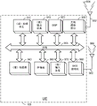
Referring now to fig. 3A-3B, fig. 3A illustrates an example system 300 for dual static radio-based object location detection. The system 300 in this example includes a radio base station 310 (e.g., the base station 120 of fig. 1 and/or the gNB 210 or ng-eNB 214 of fig. 2) and a user equipment 320 (e.g., the UE105 of fig. 1 and/or 2), each of which may be referred to as a "wireless device. Additionally, the object 330 is in an environment served by the base station 310. In this example, the base station 310 and the user equipment 320 may communicate using a 5G frequency band (e.g., 28 GHz). However, other millimeter wave (or "mm wave") radio frequencies may also be used, including frequencies ranging from 30 to 300GHz, including, for example, frequencies utilized by the 802.11ad Wi-Fi standard (operating at 60 GHz). Because positioning functionality according to the present disclosure may be performed in the same frequency band as communication, hardware may be used for both communication and position sensing. For example, one or more components in the system 300 shown in fig. 3A may employ a wireless modem (e.g., a Wi-Fi or 5G modem).
In this example, base station 310 is a 5G wireless base station as discussed above with reference to fig. 1-2, but in other examples, base station 310 may be any suitable wireless access point to the network, such as a Wi-Fi access point. Similarly, the user device 320 depicted in fig. 3A is a 5G wireless device, but in other examples it may employ any suitable wireless communication technology, including Wi-Fi. For example, hardware for implementing the functionality described in this disclosure may be integrated into mobile phones and many other types of devices or vehicles. These may include, for example, other mobile devices (e.g., tablets, portable media players, laptops, wearable devices, virtual Reality (VR) devices, augmented Reality (AR) devices), and other electronic devices (e.g., security devices, systems on vehicles). The electronic device is not limited to mobile devices and instead may be integrated into a stationary wireless station and thus may be installed in or on a building or other structure.
One of the advantages of using wireless technology in some examples is that existing wireless devices may be used to perform object location detection. For example, conventional wireless networks (e.g., 5G wireless networks) may implement the software for performing the functionality described herein using existing infrastructure. Any suitable wireless signal may be used as the reference signal discussed herein. Similarly, wi-Fi or other access point-based communication networking modalities may be used in some examples. These access points or base stations may coordinate with other wireless devices to detect objects in the environment and determine their locations.
Fig. 3B illustrates the use of a technique for determining the position of an object 300 in an environment served by a base station 310 according to the present disclosure. When the base station 310 and the user equipment 320 communicate, they each transmit radio signals that propagate through the environment and reach the other device. In an idealized environment comprising only the user equipment 320 and the base station 310, the wireless signal will traverse a direct path 340 between the two devices 310, 320; however, in reality, the transmitted wireless signal may also reflect off other objects in the area, resulting in potentially many reflected versions of the signal reaching the receiving antenna. For example, a base station 310 using an omni-directional transmitter will transmit signals in multiple directions simultaneously. As these signals propagate, they encounter objects and reflect off of them, eventually reaching the receiving antenna. This propagation of multiple versions of the same signal (e.g., due to reflection) is commonly referred to as "multipath. Examples in accordance with the present disclosure utilize such multipath signal propagation, as will be discussed in more detail below.
In addition to such omni-directional transmissions, some base stations 110 may employ beamforming to transmit signals into the environment. For example, a base station may sweep a beam through the environment across some arc (e.g., 90 degrees, 120 degrees) to transmit signals. Thus, as the base station 110 sweeps the signal through the environment, at some time it will be directed to the receiving antenna, which will then receive the signal via the direct transmission path. At other times, the beam may be reflected by objects in the environment and eventually reach the receiving antenna via a reflected path. Although two different signals will have many of the same characteristics, such as data encoded on a beam, they will be transmitted at different times and thus may be considered separate signals, although both are conceptually the same signal. However, techniques according to the present disclosure may employ omni-directional signal transmission or beamformed signal transmission.
In this example, the environment includes a base station 310 and a user equipment 320, as well as an object 330. Thus, as the transmitted signals propagate between the base station 310 and the user equipment 320, some signals are received via the direct path 340 and some signals are reflected off the object 330 via the reflected paths 342 a-b. By determining the signal characteristics of each type of received signal (direct and reflected paths) and by knowing the location (X) of one or both of the wireless devices 310, 320 BS ,Y BS ) Or (X) UD ,Y UD ) The position (X) of object 330 may be determined O ,Y O )。
Referring now to fig. 4A-4B, fig. 4A illustrates an ellipse 400 and corresponding ellipse information that may be used to locate an object at any point on the ellipse 400, so long as some information is known. The ellipse is composed of two foci F 1 And F 2 Semi-major axis a and semi-minor axis b. The ellipse then includes a focal point F 1 And F 2 With the same distance sum | PF 1 |+|PF 2 All points of. In the system 300 shown in fig. 3A, the ellipse may be determined by setting the base station 310 and the user equipment 320 to a focus and using ToF information of a reflected signal from the object 330. For example, at F 1 And is located at F (e.g., base station 310) 2 Will correspond to | PF, a time-of-flight measurement between a receiving antenna array (e.g., user equipment 320) in which the wireless signal reflects off of object 330 at point P 1 |+|PF 2 Distance measurement of | is performed. An ellipse may then be calculated using the two focal points and the distance measurement (as discussed above), and the location of the object may be estimated based on the geometry of the ellipse and the determined signal characteristics.
For example, according to some examples where the system for dual static radio based object location detection detects an object, the object may be considered to be on the ground or on nearly the same horizontal plane as both the base station 310 and the user equipment 320. ( It may be noted that in some examples, the antenna elements may be offset from a coordinate system used to establish azimuth and elevation angles. In such examples, the determination of the ellipse and the distance may account for the deviation. )
Fig. 4B illustrates how the geometry of an ellipse may be utilized to determine the location of an object (e.g., object 330). As discussed above, the wireless device determines the ToF and AoA of the received signal (e.g., the wireless signal following reflected path 342 a-b). Thus, depending on which wireless device 310, 320 receives the reflected signal 342a-b, the AoA will correspond to θ 1 Or theta 2 One of them. The position of the object may then be calculated based on the properties of the ellipse. First, the semi-major and semi-minor axis lengths may be determined by the following equations:
a=|PF 1 |+|PF 2 |, (1)
and is provided with

The ellipse itself can then be calculated as follows:

equation (3) assumes that the center of the ellipse (and focus F) 1 And F 2 Collinear and equidistant points) is (0,0), which may be used for computational purposes before mapping an ellipse to another coordinate system (e.g., based on latitude and longitude).
Once the shape of the ellipse is known, it can be based on the AoA θ determined at the respective devices 1 Or theta 2 To determine the position of the object. The corresponding point P on the ellipse is the position of the object. For example, a ray originating from one of the foci and cast at AoA will intersect the ellipse at the object location represented by point P. Thus, by finding the intersection between the ray and the ellipse, the location of the object can be determined.
Alternatively, the ellipse may be defined using polar coordinates relative to one of the two foci, which may provide another way to determine the location of any point on the ellipse given the AoA. The two axes are determined as discussed above with reference to equations (1) and (2). Next, the eccentricity of the ellipse is determined by:

finally, an ellipse is calculated based on the focus and the angle θ:

thus, using the ellipse and the known AoA, the location of the object can be determined.
Fig. 5 is a diagram of an example system 500 for dual static radio-based object location detection. System 500 is attempting to determine the location of target 530 in accordance with the techniques disclosed herein. As discussed above, the base station 510 and the user equipment 520 communicate using RF signals that traverse the environment surrounding the user equipment 520 and the base station 510. (again, base station 510 and user equipment 520 may correspond to base stations and/or user equipment/mobile devices as previously described.) ideally, the signal would traverse a direct path 540 between base station 510 and user equipment 520, however, some signal reflections would occur, resulting in multiple copies of the same signal arriving at the receiving device at different times.
In this example, one of the two wireless devices (i.e., base station 510 and user equipment 520) attempts to determine the location of one or more objects in the environment. For purposes of this example, base station 510 attempts to determine the location of target 530, although this may also be done by user equipment 520. The base station 510 starts by determining its location and the location of the user equipment 520, e.g. requesting the location from the user equipment 520 or determining the location of the user equipment (e.g. by using RTT and AoA techniques to determine the distance and orientation to the user equipment 520).
The base station 510 then transmits a reference signal to another device. The reference signal is any suitable signal transmitted using the available RF bandwidth for assisting in determining the location of the target 530. For example, the reference signal may be transmitted using beamforming techniques to direct the reference signal to a remote device. In some examples, the reference signal may be transmitted omni-directionally. In such examples, although many copies of the reference signal may arrive at the user equipment 520, the first arriving copy may be identified as having taken the most direct path, illustrated in fig. 5 as an idealized straight-line direct path 540.
The user equipment 520 then receives a reflected version of the reference signal that has encountered the target while propagating through the environment. In examples where beamforming techniques are used to transmit the reference signal, the reflected version of the reference signal may be a signal transmitted at a different time than the beamformed signal transmitted to the remote device. For example, the transmitting party may direct a beam to a target object in the environment, and the remote device may detect a reflection of the beam off the target object. In some examples, where the transmitter transmits the reference signal omnidirectionally, the reflected signal may be transmitted at the same time as the signal traversing the direct path 540 from the transmitter to the remote device. In either case, the reflected signal follows the paths 542a-b shown in FIG. 5. User equipment 520 then calculates the ToF and AoA of the reflected signal using conventional wireless signal processing techniques, i.e.
After calculating these two parameters, the user equipment 520 then communicates them to the base station 510, and the base station 510 receives the parameters and determines the location of the target. First, base station 510 determines the shape of the ellipse based on the ToF of reflected paths 542a-B, as described above with reference to FIG. 4B. Because all points on the ellipse have the same combined distance to each of the two foci, a single ellipse is determined based on ToF. This is because ToF represents the distance traveled from base station 510 to user equipment 520 when the reference signal is reflected off of target 530.
Additionally, based on the AoA of the reflected signal at the user device 520, a single point on the ellipse may be identified by extending a ray outward from the user device 520 at the AoA of the reflected signal. The point at which the ray intersects the ellipse represents the location of the target 530. For example, as illustrated above with respect to equation 5, once the various properties of an ellipse are known, a point on the ellipse may be determined based on the location of the focus and the angle from the focus. The location on the ellipse may then be mapped to a geographic coordinate system (such as latitude and longitude) to obtain the location of the target 530.
As described above, while the base station 510 initiates positioning functionality and transmits reference signals, in some examples, the user equipment 510 may perform either or both of such functionalities. Further, although the user equipment 520 receives the reference signal and calculates the ToF and AoA parameters, these parameters may instead be determined by the base station 510. Further, the base station 510 or the user equipment 520 may determine the location of the target based on the determined ToF and AoA parameters.
Fig. 6 is a flow diagram of a method 600 for dual static radio based object location detection, in accordance with an embodiment. This example method 600 will be discussed with reference to the example system 500 shown in fig. 5, although it may be performed by any system according to the present disclosure. For example, some or all of the operations illustrated in method 600 may be performed by a base station 120 (e.g., base station 510) or a UE105 (e.g., user equipment 520). Example hardware and/or software components that may be used for these operations performed by base station 120 or UE105 are provided in fig. 9 and 10, respectively, discussed in more detail below.
The functionality at block 610 includes obtaining, at a first wireless device, a location of a second wireless device. As mentioned below with respect to block 630, the first wireless device may be a transmitting device and the second wireless device may be a receiving device, or vice versa. In an example, the first wireless device may obtain the location of the second wireless device using any of the positioning techniques discussed above with reference to fig. 1 and 2. Additionally or alternatively, the method 600 may include requesting, by the first wireless device, a location of the second wireless device from the second wireless device, wherein obtaining the location of the second wireless device may include receiving, by the first wireless device, the location of the second wireless device from the second wireless device. For example, the second wireless device may comprise a user device that determines its own location, such as by using a suitable GNSS (such as GPS), or by using RF techniques (such as trilateration based on received wireless signals), wi-Fi (or other WLAN) positioning, and so forth. However, in some examples, the first wireless device may include the base station 510, and the base station 510 may obtain the location of the user device 520 based on determining the RTT of a signal transmitted by the base station 510, such as a reference signal, and a corresponding response sent by the second wireless device (user device 520), and the AoA of the response received by the base station 510. The RTT indicates the ToF from the base station 510 to the user equipment 520 and the ToF from the user equipment to the base station 510 (plus some processing time at the user equipment 520). Thus, RTT gives a close approximation of the distance between the base station and the user equipment, e.g. (RTT/2) × c, where c is the speed of light. In addition, the base station 510 determines the orientation to the user equipment 520 by determining the AoA of the user equipment's response. Thus, the base station may calculate the location of the user equipment based on the location of the base station, the distance to the user equipment, and the orientation to the user equipment.
Although the above examples contemplate the base station 510 obtaining the location of the user device 520, in some examples, the user device 520 may instead obtain the location of the base station 510. For example, the user equipment 520 may request the location of the base station from the base station 510 or it may obtain the location of the base station based on the RTT and AoA techniques discussed above or any other suitable technique. Thus, the first wireless device and the second wireless device of method 600 each correspond to base station 510 and user equipment 520, respectively, or vice versa. That is, according to some embodiments of the method 600, the first wireless device comprises a first base station and the second wireless device comprises a second base station or a wireless user equipment. Alternatively, according to some embodiments, the first wireless device comprises a first wireless user equipment and the second wireless device comprises a second wireless user equipment or a base station.
Other suitable means for determining the location of the second wireless device include software executed by a processor configured to determine RTT and AoA as discussed above. In some examples, suitable means for obtaining the location of the second wireless device includes a radio transceiver and antenna for transmitting signals to the second wireless device and receiving responses from the second wireless device indicative of the location of the second wireless device, as discussed above. However, any suitable means for determining the location of the second wireless device may be employed in accordance with the present disclosure.
At block 620, the functionality includes: the method includes obtaining, at a first wireless device, toF and AoA of a wireless WWAN reference signal transmitted by a transmitting device, wherein the ToF and AoA are obtained from measurements of the WWAN reference signal at a receiving device after the WWAN reference signal is reflected by an object. According to some embodiments, the first wireless device may transmit a reference signal to the second wireless device as discussed above with reference to fig. 5, the reference signal reflecting off of the target 530. The second wireless device may then receive the reflected version of the signal, and based on determining that the received signal is a reference signal for object location detection, it may determine the ToF and AoA of the reflected version of the signal (corresponding to the reference signal following reflected paths 542 a-b). It should be appreciated that in some examples, the AoA of the reflected reference signal may be determined relative to the AoA of the direct transmission path 540. That is, the AoA of the WWAN reference signal at block 620 of fig. 6 may include a DAoA that indicates an angle between a reflected path of the WWAN reference signal and a direct path between the first wireless device and the second wireless device. However, in some examples, the AoA of the reflected reference signal may not be determined with reference to the AoA of the direct transmission path. In accordance with some embodiments, the first device may transmit the WWAN reference signal using a first beam and a second beam. In these embodiments, the WWAN reference signal transmitted using the first beam may travel a direct path to the second device and the WWAN reference signal transmitted using the second beam may be reflected by the object.
In some examples, the first wireless device may itself determine the ToF and AoA to obtain those parameters. For example, a first wireless device including base station 510 may not transmit a reference signal to a second wireless device (e.g., user equipment 520) but receive a reference signal transmitted by the second wireless device. In response to receiving one or more reflected versions of the reference signal, the first wireless device may determine the ToF and AoA of the received reflected reference signal to obtain those parameters.
With this in mind and as described in more detail below, variations of method 600 may occur. For example, in accordance with some embodiments, the first device comprises a transmitting device and the second device comprises a receiving device, and obtaining the ToF and AoA of the WWAN reference signal comprises receiving, at the first wireless device, signal information from the second wireless device, the signal information comprising an indication of the ToF and an indication of the AoA of the WWAN reference signal. In accordance with some embodiments, the first device comprises a receiving device and the second device comprises a transmitting device, and obtaining the ToF and AoA of the WWAN reference signal comprises taking measurements of the WWAN reference signal by the first device to obtain the ToF and AoA.
Suitable means for obtaining ToF and AoA parameters of the reflected reference signal include a radio receiver and an antenna. As discussed above, obtaining ToF and AoA parameters may include transmitting a signal to a remote wireless device and receiving a response including an indication of the ToF and AoA parameters. In some examples, the means for obtaining may include (or may be) means for determining ToF and AoA of the received wireless signal, may include a radio receiver and antenna and software for determining time differences of arrival of signals arriving at different elements of the antenna, e.g., based on phase differences of the signals received at the antenna elements. Further, the software may determine the ToF based on synchronized clocks or time references at the transmitting and receiving devices and based on a transmission scheme (where transmission of certain signals is made at some predetermined time within the transmission scheme). ToF may represent an offset or delay from a predetermined transmission time that is measurable at the receiver. However, any suitable means for obtaining reflected ToF and AoA for WWAN reference signals reflected by a remote object or means for determining reflected ToF and AoA for WWAN reference signals reflected by a remote object may be employed in accordance with the present disclosure.
At block 630, the functionality includes: determining, by the first wireless device, a location of the object based on the location of the second wireless device, the ToF and the AoA, wherein (i) the first device comprises a transmitting device and the second device comprises a receiving device, or (ii) the first device comprises a receiving device and the second device comprises a transmitting device. In this example, the first wireless device may determine the location of the remote object based on an ellipse generated from the reflected ToF. As discussed above with reference to fig. 4A-4B and 5, the ellipse may be determined based on the reflected ToF and one or both of the location of the wireless device and the location of the remote wireless device. After generating the ellipse, the first wireless device (e.g., base station 510) may determine an intersection between a ray extending from the location of the second wireless device (e.g., location 520 of the user device) at the AoA and the ellipse. The location of the intersection point indicates the location of the remote object (e.g., target 530). In some examples, the first wireless device may employ one or more of equations 1-5 to determine the intersection between the ray and the ellipse.
In some examples, the first wireless device may employ a geographic coordinate system, for example, in defining an ellipse. Thus, when the first wireless device determines the location of the intersection between the ray and the ellipse, the location may be represented by further geographic coordinates. However, in examples where the first wireless device uses a different coordinate system (e.g., the ellipse is centered around a hypothetical origin having coordinates (0,0)), the first wireless device may then map the ellipse from the hypothetical coordinate system to another coordinate system (e.g., an absolute coordinate system, such as latitude and longitude). The mapping may be performed by, for example, calculating an offset from the imaginary coordinate system to coordinates in the further coordinate system for the positions of the first wireless device and the second wireless device. These offsets may then be applied to the coordinates of the intersection between the ray and the ellipse. And while the example relates to the first wireless device determining the location of the remote object, it should be appreciated that in some examples, the second wireless device may determine the location of the remote object. Suitable means for determining the location of the remote object based on the location of the remote wireless device may include software or hardware programmed to perform the functionality discussed above with reference to block 630 and fig. 4A-4B and 5 to generate an ellipse and determine an intersection between a ray extending from the remote wireless device at AoA and the ellipse.
Although the example method 600 shown in fig. 6 is described above as being performed by a first wireless device comprising the base station 510 based on information received from a second wireless device comprising the user equipment 520, it should be appreciated that the base station 510 and the user equipment 520 may each perform the functionality of the first or second wireless device of the method 600. Further, it should be appreciated that in some examples, the ToF and AoA information may be determined by a remote wireless device and obtained by the wireless device, or the wireless device may receive a reference signal from the remote wireless device and determine the ToF and AoA locally. Thus, there are at least four different permutations of the method 600 discussed above. First, the base station 510 comprises a first wireless device that performs the method 600 and transmits a reference signal to a user equipment 520 comprising a second wireless device, the user equipment 520 responding with ToF and AoA information. Second, the base station 510 includes a first wireless device that performs the method 600, receives reference signals from the user equipment 520 including a second wireless device, and determines ToF and AoA information and a location of a remote object. Third, the user equipment 520 comprises a first wireless device that performs the method and transmits a reference signal to a base station 510 comprising a second wireless device, the base station 510 responding with ToF and AoA information. Fourth, the user equipment 520 comprises a first wireless device that performs the method 600, receives reference signals from a base station 510 comprising a second wireless device, and determines ToF and AoA information and a location of a remote object. These variations will be illustrated and described below with reference to fig. 7-8.
Fig. 7 is a flow diagram of another example method 700 for dual static radio-based object location detection. This example method 700 will be discussed with reference to the example system 500 shown in fig. 5, although it may be performed by any system according to the present disclosure. The method of fig. 7 illustrates an example method in which a device that determines the location of a remote object transmits a reference signal to a remote wireless device to receive signal characteristics, including ToF and AoA, of the reference signal reflected from the remote object.
At block 710, the wireless device obtains a location of a remote wireless device, substantially as discussed above with reference to block 610. For example, the base station 510 may determine the location of the user equipment 520, or the user equipment 520 may determine the location of the base station 510.
At block 720, the wireless device transmits a reference signal to a remote wireless device. As discussed above, the base station 510 or the user equipment 520 may transmit a reference signal. Furthermore, any suitable reference signal may be employed. For example, existing signals defined by the wireless specification may be employed, or separate signals specifically defined for dual static radio-based object location detection may be employed. The means for transmitting the reference signal may comprise a radio transmitter and an antenna. Further, in some examples, the apparatus may include software or hardware programmed to generate suitable information to be encoded onto the radio waves according to the definition of the reference signal by the corresponding specification.
At block 730, the wireless device receives an indication of ToF and AoA of the reference signal reflected by the remote object, substantially as discussed above with reference to block 620.
At block 740, the wireless device determines the location of the remote object, substantially as discussed above with reference to block 630.
Referring now to fig. 8, fig. 8 illustrates another example method 800 for dual static radio-based object location detection. This example method 800 will be discussed with reference to the example system 500 shown in fig. 5, although it may be performed by any system according to the present disclosure. The method of fig. 8 illustrates an example method in which a device that determines a location of a remote object receives reference signals from a remote wireless device and determines signal characteristics of the reference signals reflected from the remote object, including ToF and AoA.
At block 810, the wireless device obtains a location of a remote wireless device, substantially as discussed above with reference to block 610. For example, the base station 510 may determine the location of the user equipment 520, or the user equipment 520 may determine the location of the base station 510.
At block 820, the wireless device receives a reference signal from a remote wireless device. As discussed above, the base station 510 or the user equipment 520 may receive the reference signal. Further, any suitable reference signal may be employed, as discussed above with reference to block 520. The means for receiving the reference signal may comprise a radio receiver and an antenna. Further, in some examples, the apparatus may include software or hardware programmed to decode the received reference signal according to a definition of the reference signal by a corresponding specification.
At block 830, the wireless device determines the ToF and AoA of the reference signal reflected by the remote object, substantially as discussed above with reference to block 620.
At block 840, the wireless device determines the location of the remote object, substantially as discussed above with reference to block 630.
Fig. 9 illustrates an example of a UE105, which may be utilized as described herein above (e.g., in association with fig. 1-8). For example, the UE105 may perform one or more functions of the methods illustrated in fig. 6-8. It should be noted that fig. 9 is intended merely to provide a generalized illustration of various components, any or all of which may be utilized as appropriate. It may be noted that in some instances, the components illustrated by fig. 9 may be localized to a single physical device and/or distributed among various networked devices that may be disposed at different physical locations. Further, as previously mentioned, the functionality of the UE described in the previously described examples may be performed by one or more of the hardware and/or software components illustrated in fig. 9.
The UE105 is shown as including hardware elements that may be electrically coupled via a bus 905 (or may be otherwise in communication, as appropriate). Hardware elements may include processing unit(s) 910 that may include, but are not limited to, one or more general-purpose processors, one or more special-purpose processors (such as DSP chips, graphics acceleration processors, application Specific Integrated Circuits (ASICs), and the like), and/or other processing structures or devices. As shown in fig. 9, some examples may have a separate DSP 920 depending on the desired functionality. Wireless communication-based location determination and/or other determinations may be provided in processing unit(s) 910 and/or wireless communication interface 930 (discussed below). The UE105 may also include one or more input devices 970, which may include, but are not limited to, a keyboard, a touchscreen, a touchpad, a microphone, key(s), dial(s), switch(s), etc.; the one or more output devices 915 may include, but are not limited to, a display, light Emitting Diodes (LEDs), speakers, and the like.
The UE105 may also include a wireless communication interface 930, which wireless communication interface 930 may include, but is not limited to, a modem, a network card, an infrared communication device, a wireless communication device, and/or a chipset (such as Devices, IEEE 802.11 devices, IEEE 802.15.4 devices, wi-Fi devices, wiMAX devices, WAN devices, and/or various cellular devices, etc.), which may enable the UE105 to communicate with other devices as described in the examples above.
 Wireless communication interface 930 may permit data and signaling to be communicated (e.g., transmitted and received) with a network (e.g., via an eNB, a gNB, a ng-eNB, an access point, various base stations, and/or other access node types, a TRP and/or other network components, a computer system, and/or any other electronic device described herein). Communication may be performed via one or more wireless communication antennas 932 that transmit and/or receive wireless signals 934. According to some examples, the wireless communication antenna(s) 932 can include multiple discrete antennas, antenna arrays, or any combination thereof.
Depending on the desired functionality, the wireless communication interface 930 may include a separate receiver and transmitter, or any combination of transceivers, transmitters, and/or receivers, to communicate with base stations (e.g., ng-enbs and gnbs) and other terrestrial transceivers, such as wireless devices and access points. The UE105 may communicate with different data networks, which may include various network types. For example, a Wireless Wide Area Network (WWAN) may be a CDMA network, a Time Division Multiple Access (TDMA) network, a Frequency Division Multiple Access (FDMA) network, an Orthogonal Frequency Division Multiple Access (OFDMA) network, a single carrier frequency division multiple access (SC-FDMA) network, a WiMAX (IEEE 802.16) network, and so forth. A CDMA network may implement one or more RATs, such as CDMA2000, WCDMA, etc. CDMA2000 includes IS-95, IS-2000, and/or IS-856 standards. A TDMA network may implement GSM, digital advanced Mobile Phone System (D-AMPS), or some other RAT. An OFDMA network may employ LTE, LTE-advanced, 5G NR, and so on. 5G NR, LTE-advanced, GSM, and WCDMA are described in documents from 3 GPP. CDMA2000 is described in a document from an organization named "third generation partnership project 2" (3 GPP 2). The 3GPP and 3GPP2 documents are publicly available. A Wireless Local Area Network (WLAN) may also be an IEEE 802.11x network, while a Wireless Personal Area Network (WPAN) may be a bluetooth network, an IEEE 802.15x, or some other type of network. The techniques described herein may also be used for any combination of WWAN, WLAN, and/or WPAN.
The UE105 may further include sensor(s) 940. The sensors 940 may include, but are not limited to, one or more inertial sensors and/or other sensors (e.g., accelerometer(s), gyroscope(s), camera(s), magnetometer(s), altimeter(s), microphone(s), proximity sensor(s), light sensor(s), barometer(s), etc.), some of which may be used to obtain positioning-related measurements and/or other information, as described herein.
Examples of the UE105 may also include a Global Navigation Satellite System (GNSS) receiver 980 capable of receiving signals 984 from one or more GNSS satellites using an antenna 982 (which may be the same as the antenna 932). Positioning based on GNSS signal measurements may be used to supplement and/or incorporate the techniques described herein. GNSS receiver 980 may use conventional techniques to extract the location of UE105 from GNSS SVs 190 of GNSS systems such as Global Positioning System (GPS), galileo, GLONASS, quasi-zenith satellite system (QZSS) above japan, indian Regional Navigation Satellite System (IRNSS) above india, beidou above china, etc. Further, GNSS receiver 980 may be used for various augmentation systems (e.g., satellite-based augmentation systems (SBAS)) such as WAAS, EGNOS, multi-functional satellite augmentation systems (MSAS), and geo-augmented navigation systems (GAGAN), among others, that may be associated with or otherwise enabled for use with one or more global and/or regional navigation satellite systems.
The UE105 may further include memory 960 and/or be in communication with memory 960. The memory 960 may include, but is not limited to, local and/or network accessible storage, disk drives, drive arrays, optical storage devices, solid state storage devices such as Random Access Memory (RAM) and/or Read Only Memory (ROM), which may be programmable, flash updateable, and the like. Such storage devices may be configured to implement any appropriate data storage, including but not limited to various file systems, database structures, and/or the like.
The memory 960 of the UE105 may also include software elements (not shown in fig. 9) including an operating system, device drivers, executable libraries, and/or other code (such as one or more applications) that may include computer programs, and/or may be designed to implement the methods, and/or configure the systems, provided by the various examples, as described herein. By way of example only, one or more procedures described with respect to the method(s) discussed above may be implemented as code and/or instructions in the memory 960 that may be executed by the UE105 (and/or the processing unit(s) 910 or DSP 920 within the UE 105). In an aspect, such code and/or instructions may then be used to configure and/or adapt a general purpose computer (or other device) to perform one or more operations in accordance with the described methods.
Fig. 10 illustrates an example of a base station 120, which can be utilized as described herein above (e.g., in association with fig. 1-8). It should be noted that fig. 10 is intended merely to provide a generalized illustration of various components, any or all of which may be utilized as appropriate. In some examples, base station 120 may correspond to a gNB, ng-eNB, and/or (more generally) a TRP.
The base station 120 may also include a wireless communication interface 1030, the wireless communication interface 1030 may include, but is not limited to, a modem, a network card, an infrared communication device, a wireless communication device, and/or a chipset (such as Devices, IEEE 802.11 devices, IEEE 802.15.4 devices, wiFi devices, wiMAX devices, cellular communication facilities, etc.), etc., that may enable
 base station 120 to communicate as described herein. The wireless communication interface 1030 may permit data and signaling to be communicated (e.g., transmitted and received) to UEs, other base stations/TRPs (e.g., enbs, gnbs, and ng-enbs), and/or other network components, computer systems, and/or any other electronic devices described herein. Communication can be performed via one or more wireless communication antennas 1032 that transmit and/or receive wireless signals 1034.
The base station 120 may also include a network interface 1080, which may include support for wired communication technologies. Network interface 1080 may include a modem, a network card, a chipset, or the like. Network interface 1080 may include one or more input and/or output communication interfaces to permit data to be exchanged with a network, a communications network server, a computer system, and/or any other electronic device described herein.
In many examples, base station 120 can further include memory 1060. The memory 1060 may include, but is not limited to, local and/or network accessible storage, disk drives, arrays of drives, optical storage devices, solid state storage devices (such as RAM and/or ROM), which may be programmable, flash updateable, and the like. Such storage devices may be configured to implement any appropriate data storage, including but not limited to various file systems, database structures, and/or the like.
Memory 1060 of base station 120 may also include software elements (not shown in fig. 10) including an operating system, device drivers, executable libraries, and/or other code (such as one or more applications) that may include computer programs provided by the various examples, and/or may be designed to implement methods provided by other examples, and/or to configure systems provided by other examples, as described herein. By way of example only, one or more of the procedures described with respect to the method(s) discussed above may be implemented as code and/or instructions in the memory 1060 that may be executed by the base station 120 (and/or the processing unit(s) 1010 or the DSP 1020 within the base station 120). In an aspect, such code and/or instructions may then be used to configure and/or adapt a general purpose computer (or other device) to perform one or more operations in accordance with the described methods.
It will be apparent to those skilled in the art that substantial variations may be made in accordance with specific requirements. For example, customized hardware might also be used and/or particular elements might be implemented in hardware, software (including portable software, such as applets, etc.), or both. In addition, connections to other computing devices (such as network input/output devices) may be employed.
Referring to the figures, components that may include memory may include non-transitory machine-readable media. The terms "machine-readable medium" and "computer-readable medium" as used herein refer to any storage medium that participates in providing data that causes a machine to operation in a specific fashion. In the examples provided above, various machine-readable media may be involved in providing instructions/code to a processing unit and/or other device(s) for execution. Additionally or alternatively, a machine-readable medium may be used to store and/or carry such instructions/code. In many implementations, the computer-readable medium is a physical and/or tangible storage medium. Such a medium may take many forms, including but not limited to, non-volatile media, and transmission media. Common forms of computer-readable media include, for example: magnetic and/or optical media, any other physical medium with patterns of holes, a RAM, a Programmable ROM (PROM), an Erasable PROM (EPROM), a FLASH-EPROM, any other memory chip or cartridge, a carrier wave as described hereinafter, or any other medium from which a computer can read instructions and/or code.
The methods, systems, and devices discussed herein are examples. Various examples may omit, substitute, or add various procedures or components as appropriate. For example, features described with reference to certain examples may be combined in various other examples. The different aspects and elements of the examples may be combined in a similar manner. The various components of the figures provided herein may be embodied in hardware and/or software. Moreover, the technology may evolve, and thus many of the elements are examples that do not limit the scope of the present disclosure to those particular examples.
It has proven convenient at times, principally for reasons of common usage, to refer to such signals as bits, information, values, elements, symbols, characters, variables, terms, numbers, numerals, or the like. It should be understood, however, that all of these and similar terms are to be associated with the appropriate physical quantities and are merely convenient labels. Unless specifically stated otherwise, as apparent from the above discussion, it is appreciated that throughout this specification discussions utilizing terms such as "processing," "computing," "calculating," "determining," "ascertaining," "identifying," "associating," "measuring," "performing," or the like refer to actions or processes of a specific apparatus, such as a special purpose computer or a similar special purpose electronic computing device. In the context of this specification, therefore, a special purpose computer or a similar special purpose electronic computing device is capable of manipulating or transforming signals, typically represented as physical, electronic, electrical, or magnetic quantities within memories, registers, or other information storage devices, transmission devices, or display devices of the special purpose computer or similar special purpose electronic computing device.
The terms "and" or "as used herein may include a variety of meanings that are also contemplated depending, at least in part, on the context in which such terms are used. In general, "or" if used to associate a list, such as A, B or C, is intended to mean A, B and C (used herein in an inclusive sense) and A, B or C (used herein in an exclusive sense). In addition, the term "one or more" as used herein may be used to describe any feature, structure, or characteristic in the singular or may be used to describe some combination of features, structures, or characteristics. It should be noted, however, that this is merely an illustrative example and that claimed subject matter is not limited to this example. Furthermore, the term "at least one of the following" if used to associate a list, such as A, B or C, may be interpreted to mean any combination of A, B and/or C, such as a, AB, AA, AAB, AABBCCC.
Having described several examples, various modifications, alternative constructions, and equivalents may be used without departing from the spirit of the disclosure. For example, the above elements may be merely components of a larger system, where other rules may take precedence over or otherwise modify the application of the various examples. Further, several steps may be taken before, during, or after the above elements are considered. Accordingly, the above description does not limit the scope of the present disclosure.
In view of this description, embodiments may include different combinations of features. Various implementation examples are described in the following numbered clauses.
Clause 1. A method for dual static radio based object location detection, the method comprising: obtaining, at a first wireless device, a location of a second wireless device; obtaining, at a first wireless device, a time-of-flight (ToF) and an angle-of-arrival (AoA) of a Wireless Wide Area Network (WWAN) reference signal transmitted by a transmitting device, wherein the ToF and the AoA are obtained from measurements of the WWAN reference signal at the receiving device after the WWAN reference signal is reflected by an object; and determining, by the first wireless device, a location of the object based on the location of the second wireless device, the ToF and the AoA; wherein: the first wireless device comprises a transmitting device and the second wireless device comprises a receiving device, or the first wireless device comprises a receiving device and the second wireless device comprises a transmitting device.
Clause 2. The method of clause 1, wherein the AoA of the WWAN reference signal includes a differential AoA (DAoA) indicating an angle between a reflected path of the WWAN reference signal and a direct path between the first wireless device and the second wireless device.
Clause 3. The method of any of clauses 1-2, further comprising requesting, by the first wireless device, the location of the second wireless device from the second wireless device, wherein obtaining the location of the second wireless device comprises receiving, by the first wireless device, the location of the second wireless device from the second wireless device.
Clause 4. The method of any of clauses 1-3, wherein the first wireless device comprises a transmitting device and the second wireless device comprises a receiving device; and obtaining the ToF and AoA of the WWAN reference signal includes receiving, at the first wireless device, signal information from the second wireless device, the signal information including an indication of the ToF and an indication of the AoA of the WWAN reference signal.
Clause 5. The method of clause 4, wherein the first wireless device transmits the WWAN reference signal using the first beam and the second beam; and wherein: the WWAN reference signal transmitted using the first beam travels a direct path to the second wireless device and the WWAN reference signal transmitted using the second beam is reflected by the object.
Clause 6. The method of any of clauses 1-3, wherein the first wireless device comprises a receiver device and the second wireless device comprises a transmitter device; and obtaining the ToF and AoA for the WWAN reference signal includes taking measurements of the WWAN reference signal by the first wireless device to obtain the ToF and AoA.
Clause 7. The method of any of clauses 1-6, wherein the first wireless device comprises a first base station and the second wireless device comprises a second base station or a wireless user equipment.
Clause 8. The method of any of clauses 1-6, wherein the first wireless device comprises a first wireless user equipment and the second wireless device comprises a second wireless user equipment or a base station.
Clause 9. A first wireless device for dual static radio-based object location detection, the first wireless device comprising: a transceiver; a memory; and one or more processors communicatively coupled with the transceiver and the memory, wherein the one or more processors are configured to: obtaining a location of a second wireless device; obtaining a time-of-flight (ToF) and an angle-of-arrival (AoA) of a Wireless Wide Area Network (WWAN) reference signal transmitted by a transmitting device, wherein the ToF and AoA are obtained from measurements of the WWAN reference signal at the receiving device after the WWAN reference signal is reflected by an object; and determining the location of the object based on the location of the second wireless device, the ToF and the AoA, wherein: the first wireless device comprises a transmitting device and the second wireless device comprises a receiving device, or the first wireless device comprises a receiving device and the second wireless device comprises a transmitting device.
Clause 10. The first wireless device of clause 9, wherein to obtain the AoA of the WWAN reference signal, the one or more processors are configured to obtain a differential AoA (DAoA) indicating an angle between a reflected path of the WWAN reference signal and a direct path between the first wireless device and the second wireless device.
Clause 11 the first wireless device of any of clauses 9-10, wherein the one or more processors are further configured to request, via the transceiver, a location of the second wireless device, wherein to obtain the location of the second wireless device, the one or more processors are configured to receive, via the transceiver, the location of the second wireless device from the second wireless device.
Clause 12. The first wireless device of any of clauses 9-11, wherein the first wireless device comprises a transmitting device; and to obtain the ToF and AoA of the WWAN reference signal, the one or more processors are configured to receive, via the transceiver, signal information from the second wireless device, the signal information including an indication of the ToF and an indication of the AoA of the WWAN reference signal.
The first wireless device of clause 13, wherein the one or more processors are configured to transmit, via the transceiver, the WWAN reference signal using the first beam and the second beam such that: the WWAN reference signal transmitted using the first beam travels a direct path to the second wireless device and the WWAN reference signal transmitted using the second beam is reflected by the object.
Clause 14. The first wireless device of any of clauses 9-11, wherein the first wireless device comprises a recipient device; and to obtain the ToF and AoA of the WWAN reference signal, the one or more processors are configured to take measurements of the WWAN reference signal using the transceiver to obtain the ToF and AoA.
Clause 15. The first wireless device of any one of clauses 9-14, wherein the first wireless device comprises a first base station or a wireless user equipment.
Clause 16. An apparatus for dual static radio-based object location detection, the apparatus comprising: means for obtaining a location of a wireless device; means for obtaining a time-of-flight (ToF) and an angle-of-arrival (AoA) of a Wireless Wide Area Network (WWAN) reference signal transmitted by a transmitting device, wherein the ToF and AoA are obtained from measurements of the WWAN reference signal at a receiving device after the WWAN reference signal is reflected by an object; and means for determining a location of the object based on the location of the wireless device, the ToF, and the AoA, wherein: the apparatus comprises a transmitting device and the wireless device comprises a receiving device, or the apparatus comprises a receiving device and the wireless device comprises a transmitting device.
Clause 17. The apparatus of clause 16, wherein the means for obtaining the AoA of the WWAN reference signal comprises means for obtaining a differential AoA (DAoA) indicating an angle between a reflected path of the WWAN reference signal and a direct path between the apparatus and the wireless device.
Clause 18. The apparatus of any of clauses 16-17, further comprising means for requesting the location of the wireless device, wherein the means for obtaining the location of the wireless device comprises means for receiving, by the apparatus, the location of the wireless device from the wireless device.
Clause 19. The apparatus of any of clauses 16-18, wherein the apparatus comprises a transmitting device; and means for obtaining the ToF and AoA of the WWAN reference signal comprises means for receiving signal information from the wireless device at the apparatus, the signal information comprising an indication of the ToF and an indication of the AoA of the WWAN reference signal.
Clause 20. The apparatus of clause 19, wherein the apparatus transmits the WWAN reference signal using the first beam and the second beam; and wherein: the WWAN reference signal transmitted using the first beam travels a direct path to the wireless device and the WWAN reference signal transmitted using the second beam is reflected by the object.
Clause 21. The apparatus of any one of clauses 16-18, wherein the apparatus comprises a receiver device; and means for obtaining the ToF and AoA for the WWAN reference signal comprises means for taking measurements of the WWAN reference signal by the apparatus to obtain the ToF and AoA.
Clause 22. The apparatus of any one of clauses 16-21, wherein the apparatus comprises a first base station or a first wireless user equipment.
Clause 23. A non-transitory computer-readable medium storing instructions for dual static radio-based object position detection, the instructions comprising code for: obtaining, at a first wireless device, a location of a second wireless device; obtaining, at a first wireless device, a time-of-flight (ToF) and an angle-of-arrival (AoA) of a Wireless Wide Area Network (WWAN) reference signal transmitted by a transmitting device, wherein the ToF and AoA are obtained from measurements of the WWAN reference signal at the receiving device after the WWAN reference signal is reflected by an object; and determining, by the first wireless device, a location of the object based on the location of the second wireless device, the ToF and the AoA, wherein: the first wireless device comprises a transmitting device and the second wireless device comprises a receiving device, or the first wireless device comprises a receiving device and the second wireless device comprises a transmitting device.
Clause 24. The computer-readable medium of clause 23, wherein the code for obtaining the AoA of the WWAN reference signal comprises code for obtaining a differential AoA (DAoA) indicative of an angle between a reflected path of the WWAN reference signal and a direct path between the first wireless device and the second wireless device.
Clause 25. The computer-readable medium of any of clauses 23-24, wherein the instructions further comprise code for requesting a location of the second wireless device, wherein the code for obtaining the location of the second wireless device comprises code for receiving, by the first wireless device from the second wireless device, the location of the second wireless device.
Clause 26 the computer-readable medium of any of clauses 23-25, wherein the code for obtaining the ToF and AoA of the WWAN reference signal comprises means for receiving, at the first wireless device, signal information from the second wireless device, the signal information including an indication of the ToF and an indication of the AoA of the WWAN reference signal.
The computer-readable medium of clause 26, wherein the instructions include code for transmitting, by the first wireless device, the WWAN reference signal using the first beam and the second beam such that: the WWAN reference signal transmitted using the first beam travels a direct path to the second wireless device and the WWAN reference signal transmitted using the second beam is reflected by the object.
Clause 28 the computer-readable medium of any of clauses 23-25, wherein the code for obtaining the ToF and AoA of the WWAN reference signal comprises code for taking measurements of the WWAN reference signal by the first wireless device to obtain the ToF and AoA.
Claims (28)
1. A method for dual static radio based object location detection, the method comprising:
obtaining, at a first wireless device, a location of a second wireless device;
obtaining, at the first wireless device, a time-of-flight (ToF) and an angle-of-arrival (AoA) of a Wireless Wide Area Network (WWAN) reference signal transmitted by a transmitting device, wherein ToF and AoA are obtained from measurements of the WWAN reference signal at a receiving device after the WWAN reference signal is reflected by an object; and
determining, by the first wireless device, a location of the object based on the location of the second wireless device, the ToF, and the AoA;
wherein:
the first wireless device comprises the transmitting device and the second wireless device comprises the receiving device, or
The first wireless device comprises the receiver device and the second wireless device comprises the transmitter device.
2. The method of claim 1, wherein the AoA of the WWAN reference signal comprises a differential AoA (DAoA) indicating an angle between a reflected path of the WWAN reference signal and a direct path between the first wireless device and the second wireless device.
3. The method of claim 1, further comprising requesting, by the first wireless device, a location of the second wireless device from the second wireless device, wherein obtaining the location of the second wireless device comprises receiving, by the first wireless device, the location of the second wireless device from the second wireless device.
4. The method of claim 1, wherein:
the first wireless device comprises the transmitting device and the second wireless device comprises the receiving device; and is
Obtaining the ToF and the AoA of the WWAN reference signal includes receiving, at the first wireless device, signal information from the second wireless device, the signal information including an indication of the ToF and an indication of the AoA of the WWAN reference signal.
5. The method of claim 4, wherein the first wireless device transmits the WWAN reference signal using a first beam and a second beam; and wherein:
the WWAN reference signal transmitted using the first beam travels a direct path to the second wireless device, and
the WWAN reference signal transmitted using the second beam is reflected by the object.
6. The method of claim 1, wherein:
the first wireless device comprises the receiver device and the second wireless device comprises the transmitter device; and is
Obtaining the ToF and the AoA of the WWAN reference signal includes taking measurements of the WWAN reference signal by the first wireless device to obtain the ToF and the AoA.
7. The method of claim 1, wherein the first wireless device comprises a first base station and the second wireless device comprises a second base station or a wireless user equipment.
8. The method of claim 1, wherein the first wireless device comprises a first wireless user device and the second wireless device comprises a second wireless user device or a base station.
9. A first wireless device for dual static radio-based object location detection, the first wireless device comprising:
a transceiver;
a memory; and
one or more processors communicatively coupled with the transceiver and the memory, wherein the one or more processors are configured to:
obtaining a location of a second wireless device;
obtaining a time-of-flight (ToF) and an angle-of-arrival (AoA) of a Wireless Wide Area Network (WWAN) reference signal transmitted by a transmitting device, wherein ToF and AoA are obtained from measurements of the WWAN reference signal at a receiving device after the WWAN reference signal is reflected by an object; and
determining a location of the object based on the location of the second wireless device, the ToF, and the AoA, wherein:
the first wireless device comprises the transmitting device and the second wireless device comprises the receiving device, or
The first wireless device comprises the receiver device and the second wireless device comprises the transmitter device.
10. The first wireless device of claim 9, wherein to obtain the AoA of the WWAN reference signal, the one or more processors are configured to obtain a differential AoA (DAoA) that indicates an angle between a reflected path of the WWAN reference signal and a direct path between the first wireless device and the second wireless device.
11. The first wireless device of claim 9, wherein the one or more processors are further configured to request, via the transceiver, a location of the second wireless device, wherein to obtain the location of the second wireless device, the one or more processors are configured to receive, via the transceiver, the location of the second wireless device from the second wireless device.
12. The first wireless device of claim 9, wherein:
the first wireless device comprises the transmitting device; and is
To obtain the ToF and the AoA of the WWAN reference signal, the one or more processors are configured to receive signal information from the second wireless device via the transceiver, the signal information including an indication of the ToF and an indication of the AoA of the WWAN reference signal.
13. The first wireless device of claim 12, wherein the one or more processors are configured to transmit, via the transceiver, the WWAN reference signal using a first beam and a second beam such that:
the WWAN reference signal transmitted using the first beam travels a direct path to the second wireless device, and
the WWAN reference signal transmitted using the second beam is reflected by the object.
14. The first wireless device of claim 9, wherein:
the first wireless device comprises the receiver device; and is provided with
To obtain the ToF and the AoA of the WWAN reference signal, the one or more processors are configured to obtain measurements of the WWAN reference signal using the transceiver to obtain the ToF and the AoA.
15. The first wireless device of claim 9, wherein the first wireless device comprises a first base station or a wireless user device.
16. An apparatus for dual static radio-based object position detection, the apparatus comprising:
means for obtaining a location of a wireless device;
means for obtaining a time-of-flight (ToF) and an angle-of-arrival (AoA) of a Wireless Wide Area Network (WWAN) reference signal transmitted by a transmitting device, wherein ToF and AoA are obtained from measurements of the WWAN reference signal at a receiving device after the WWAN reference signal is reflected by an object; and
means for determining a location of the object based on the location of the wireless device, the ToF, and the AoA, wherein:
the apparatus comprises the transmitting device and the wireless device comprises the receiving device, or
The apparatus comprises the receiver device and the wireless device comprises the transmitter device.
17. The apparatus of claim 16, wherein the means for obtaining the AoA of the WWAN reference signal comprises means for obtaining a differential AoA (DAoA) indicative of an angle between a reflected path of the WWAN reference signal and a direct path between the apparatus and the wireless device.
18. The apparatus of claim 16, further comprising means for requesting a location of the wireless device, wherein means for obtaining the location of the wireless device comprises means for receiving, by the apparatus, the location of the wireless device from the wireless device.
19. The apparatus of claim 16, wherein:
the apparatus comprises the transmitting device; and is
Means for obtaining the ToF and the AoA of the WWAN reference signal comprises means for receiving, at the apparatus, signal information from the wireless device, the signal information comprising an indication of the ToF and an indication of the AoA of the WWAN reference signal.
20. The apparatus of claim 19, wherein the apparatus transmits the WWAN reference signal using a first beam and a second beam; and wherein:
the WWAN reference signal transmitted using the first beam travels a direct path to the wireless device, and
the WWAN reference signal transmitted using the second beam is reflected by the object.
21. The apparatus of claim 16, wherein:
the apparatus comprises the receiver device; and is
Means for obtaining the ToF and the AoA for the WWAN reference signal comprises means for taking measurements of the WWAN reference signal by the apparatus to obtain the ToF and the AoA.
22. The apparatus of claim 16, wherein the apparatus comprises a first base station or a first wireless user equipment.
23. A non-transitory computer-readable medium storing instructions for dual static radio-based object position detection, the instructions comprising code to:
obtaining, at a first wireless device, a location of a second wireless device;
obtaining, at the first wireless device, a time-of-flight (ToF) and an angle-of-arrival (AoA) of a Wireless Wide Area Network (WWAN) reference signal transmitted by a transmitting device, wherein ToF and AoA are obtained from measurements of the WWAN reference signal at a receiving device after the WWAN reference signal is reflected by an object; and
determining, by the first wireless device, a location of the object based on the location of the second wireless device, the ToF, and the AoA, wherein:
the first wireless device comprises the transmitting device and the second wireless device comprises the receiving device, or
The first wireless device comprises the receiver device and the second wireless device comprises the transmitter device.
24. The computer-readable medium of claim 23, wherein code for obtaining the AoA of the WWAN reference signal comprises code for obtaining a differential AoA (DAoA) indicative of an angle between a reflected path of the WWAN reference signal and a direct path between the first wireless device and the second wireless device.
25. The computer-readable medium of claim 23, wherein the instructions further comprise code for requesting a location of the second wireless device, wherein the code for obtaining the location of the second wireless device comprises code for receiving, by the first wireless device, the location of the second wireless device from the second wireless device.
26. The computer-readable medium of claim 23, wherein code for obtaining the ToF and the AoA of the WWAN reference signal comprises code for receiving signal information from the second wireless device at the first wireless device, the signal information comprising an indication of the ToF and an indication of the AoA of the WWAN reference signal.
27. The computer-readable medium of claim 26, wherein the instructions include code for transmitting, by the first wireless device, the WWAN reference signal using a first beam and a second beam such that:
the WWAN reference signal transmitted using the first beam travels a direct path to the second wireless device, and
the WWAN reference signal transmitted using the second beam is reflected by the object.
28. The computer-readable medium of claim 23, wherein code for obtaining the ToF and the AoA of the WWAN reference signal comprises code for taking measurements of the WWAN reference signal by the first wireless device to obtain the ToF and the AoA.
Applications Claiming Priority (5)
| Application Number | Priority Date | Filing Date | Title |
|---|---|---|---|
| US202063035091P | 2020-06-05 | 2020-06-05 | |
| US63/035,091 | 2020-06-05 | ||
| US17/335,761 | 2021-06-01 | ||
| US17/335,761 US11889462B2 (en) | 2020-06-05 | 2021-06-01 | Systems and methods for bi-static radio-based object location detection |
| PCT/US2021/035520 WO2021247755A1 (en) | 2020-06-05 | 2021-06-02 | Systems and methods for bi-static radio-based object location detection |
Publications (1)
| Publication Number | Publication Date |
|---|---|
| CN115698759A true CN115698759A (en) | 2023-02-03 |
Family
ID=78818234
Family Applications (1)
| Application Number | Title | Priority Date | Filing Date |
|---|---|---|---|
| CN202180038734.7A Pending CN115698759A (en) | 2020-06-05 | 2021-06-02 | System and method for dual static radio based object location detection |
Country Status (8)
| Country | Link |
|---|---|
| US (1) | US11889462B2 (en) |
| EP (1) | EP4162294A1 (en) |
| JP (1) | JP2023527637A (en) |
| KR (1) | KR20230020407A (en) |
| CN (1) | CN115698759A (en) |
| BR (1) | BR112022023838A2 (en) |
| TW (1) | TW202202869A (en) |
| WO (1) | WO2021247755A1 (en) |
Families Citing this family (5)
| Publication number | Priority date | Publication date | Assignee | Title |
|---|---|---|---|---|
| EP4198560A1 (en) * | 2021-12-17 | 2023-06-21 | Koninklijke Philips N.V. | Wireless communication system with distributed sensing capability |
| WO2023111169A1 (en) * | 2021-12-17 | 2023-06-22 | Koninklijke Philips N.V. | Wireless communication system with distributed sensing capability |
| EP4212910A1 (en) * | 2022-01-12 | 2023-07-19 | Deutsche Telekom AG | Method for conducting radiofrequency sensing involving a first radiofrequency sensing station and at least a second radiofrequency sensing station, wherein the first radiofrequency sensing station transmits a radiofrequency sensing signal, wherein, as a result of the radiofrequency sensing signal being transmitted, a radiofrequency sensing reception signal is received by the second radiofrequency sensing station, system or mobile communication network, radiofrequency sensing station, program and computer-readable medium |
| CN116614876A (en) * | 2022-02-08 | 2023-08-18 | 维沃移动通信有限公司 | Positioning method, positioning device, user equipment and storage medium |
| CN116939480A (en) * | 2022-04-08 | 2023-10-24 | 中国移动通信有限公司研究院 | Positioning method, positioning device, related equipment and storage medium |
Family Cites Families (8)
| Publication number | Priority date | Publication date | Assignee | Title |
|---|---|---|---|---|
| US5852630A (en) * | 1997-07-17 | 1998-12-22 | Globespan Semiconductor, Inc. | Method and apparatus for a RADSL transceiver warm start activation procedure with precoding |
| US11035940B2 (en) | 2015-07-17 | 2021-06-15 | Origin Wireless, Inc. | Method, apparatus, and system for wireless proximity and presence monitoring |
| KR101733033B1 (en) | 2016-07-08 | 2017-05-08 | 엘아이지넥스원 주식회사 | Method for estimating position using bistatic range |
| US20210116557A1 (en) | 2017-03-17 | 2021-04-22 | Sony Corporation | Radio-Based Object Detection |
| US10852411B2 (en) | 2017-12-06 | 2020-12-01 | Cognitive Systems Corp. | Motion detection and localization based on bi-directional channel sounding |
| US11402489B2 (en) * | 2019-12-17 | 2022-08-02 | Hewlett Packard Enterprise Development Lp | Passive multi-person location tracking utilizing signal polarization |
| US20220206136A1 (en) * | 2020-12-31 | 2022-06-30 | Thales Canada Inc. | Method and system for high-integrity vehicle localization |
| US11885899B2 (en) * | 2021-05-07 | 2024-01-30 | Qualcomm Incorporated | Generating indoor maps based on radio frequency sensing |
-
2021
- 2021-06-01 US US17/335,761 patent/US11889462B2/en active Active
- 2021-06-02 CN CN202180038734.7A patent/CN115698759A/en active Pending
- 2021-06-02 JP JP2022557857A patent/JP2023527637A/en active Pending
- 2021-06-02 WO PCT/US2021/035520 patent/WO2021247755A1/en active Application Filing
- 2021-06-02 EP EP21736417.3A patent/EP4162294A1/en active Pending
- 2021-06-02 KR KR1020227041548A patent/KR20230020407A/en unknown
- 2021-06-02 BR BR112022023838A patent/BR112022023838A2/en unknown
- 2021-06-04 TW TW110120479A patent/TW202202869A/en unknown
Also Published As
| Publication number | Publication date |
|---|---|
| BR112022023838A2 (en) | 2022-12-20 |
| US20210385784A1 (en) | 2021-12-09 |
| US11889462B2 (en) | 2024-01-30 |
| KR20230020407A (en) | 2023-02-10 |
| TW202202869A (en) | 2022-01-16 |
| EP4162294A1 (en) | 2023-04-12 |
| WO2021247755A1 (en) | 2021-12-09 |
| JP2023527637A (en) | 2023-06-30 |
Similar Documents
| Publication | Publication Date | Title |
|---|---|---|
| US20220065979A1 (en) | Assistance information for sidelink-assisted positioning | |
| US11889462B2 (en) | Systems and methods for bi-static radio-based object location detection | |
| US20220070712A1 (en) | Measurement report for sidelink-assisted positioning | |
| US11792666B2 (en) | Location assistance data for wideband positioning | |
| US20230408677A1 (en) | Reconfigurable intelligent surface (ris)-aided ue passive rf sensing | |
| CN116325984A (en) | Spatial relationship design for side link assisted positioning | |
| US20220003859A1 (en) | Monostatic radar with progressive length transmission | |
| WO2022246684A1 (en) | Reference signal transmission for reconfigurable intelligent surface (ris) -aided positioning | |
| US20230333194A1 (en) | Sidelink-aided hybrid network positioning | |
| US20230379867A1 (en) | Positioning of an intelligent reflecting surface (irs) in a wireless communication network | |
| US20240162940A1 (en) | Reference signal transmission for reconfigurable intelligent surface (ris)-aided positioning | |
| US20240073644A1 (en) | Location indication for uplink resources for positioning | |
| US20240098688A1 (en) | Positioning assistance data delivery for reduced signaling overhead | |
| US20240069146A1 (en) | Near/far-field determination of reconfigurable intelligent surface (ris) for mobile device positioning | |
| US20240019524A1 (en) | Reconfigurable intelligent surface (ris)-assisted timing error calibration for mobile device positioning | |
| US20240097837A1 (en) | Signaling methods for sidelink positioning for heterogeneous user equipments | |
| US20230097862A1 (en) | Positioning in a wireless network using a repeater | |
| US20240114480A1 (en) | Cross-link interference (cli)-aided hybrid network positioning | |
| CN116803154A (en) | UE passive RF sensing with cellular-based bistatic/multistatic radar |
Legal Events
| Date | Code | Title | Description |
|---|---|---|---|
| PB01 | Publication | ||
| PB01 | Publication | ||
| SE01 | Entry into force of request for substantive examination | ||
| SE01 | Entry into force of request for substantive examination |