CN115698704A - Resin pipe connecting device - Google Patents
Resin pipe connecting device Download PDFInfo
- Publication number
- CN115698704A CN115698704A CN202180040432.3A CN202180040432A CN115698704A CN 115698704 A CN115698704 A CN 115698704A CN 202180040432 A CN202180040432 A CN 202180040432A CN 115698704 A CN115698704 A CN 115698704A
- Authority
- CN
- China
- Prior art keywords
- resin
- pipe
- end surface
- metal
- axial direction
- Prior art date
- Legal status (The legal status is an assumption and is not a legal conclusion. Google has not performed a legal analysis and makes no representation as to the accuracy of the status listed.)
- Pending
Links
Images


Classifications
-
- F—MECHANICAL ENGINEERING; LIGHTING; HEATING; WEAPONS; BLASTING
- F16—ENGINEERING ELEMENTS AND UNITS; GENERAL MEASURES FOR PRODUCING AND MAINTAINING EFFECTIVE FUNCTIONING OF MACHINES OR INSTALLATIONS; THERMAL INSULATION IN GENERAL
- F16L—PIPES; JOINTS OR FITTINGS FOR PIPES; SUPPORTS FOR PIPES, CABLES OR PROTECTIVE TUBING; MEANS FOR THERMAL INSULATION IN GENERAL
- F16L21/00—Joints with sleeve or socket
- F16L21/02—Joints with sleeve or socket with elastic sealing rings between pipe and sleeve or between pipe and socket, e.g. with rolling or other prefabricated profiled rings
- F16L21/04—Joints with sleeve or socket with elastic sealing rings between pipe and sleeve or between pipe and socket, e.g. with rolling or other prefabricated profiled rings in which sealing rings are compressed by axially-movable members
-
- G—PHYSICS
- G01—MEASURING; TESTING
- G01N—INVESTIGATING OR ANALYSING MATERIALS BY DETERMINING THEIR CHEMICAL OR PHYSICAL PROPERTIES
- G01N30/00—Investigating or analysing materials by separation into components using adsorption, absorption or similar phenomena or using ion-exchange, e.g. chromatography or field flow fractionation
- G01N30/02—Column chromatography
- G01N30/60—Construction of the column
- G01N30/6034—Construction of the column joining multiple columns
-
- G—PHYSICS
- G01—MEASURING; TESTING
- G01N—INVESTIGATING OR ANALYSING MATERIALS BY DETERMINING THEIR CHEMICAL OR PHYSICAL PROPERTIES
- G01N30/00—Investigating or analysing materials by separation into components using adsorption, absorption or similar phenomena or using ion-exchange, e.g. chromatography or field flow fractionation
- G01N30/02—Column chromatography
- G01N30/60—Construction of the column
- G01N30/6004—Construction of the column end pieces
Abstract
The resin pipe connecting device of the present invention includes a resin pipe, a resin expansion portion, and a metal sleeve. The resin expansion portion includes a sealing surface contactable with the contact surface. Also, the resin expansion portion includes a second flow path that communicates with the first flow path of the resin pipe and that opens in the sealing surface. The seal surface protrudes more than the end surface of the metal sleeve in the axial direction. The maximum length of the contact area between the resin expansion part and the metal sleeve in the central axis direction of the outer side face is larger than the thickness of the resin layer in the radius direction.
Description
Technical Field
The present invention relates to a resin pipe connecting device.
Background
For example, in a liquid chromatograph, a resin tube is sometimes used when a sample that is easily adsorbed to a metal is analyzed or when a mobile phase that is corrosive to a metal is used. The resin pipe has a structure in which, for example, the inner surface of the metal pipe is covered with a resin layer. When the resin tube is connected to, for example, a separation column, it is necessary to ensure the sealing of the flow paths of the resin tube and the separation column. For this reason, a structure for sealing with an end surface of a resin pipe has been proposed. For example, patent document 1 describes a plug unit for connecting a plug capillary for a high performance liquid chromatograph.
The plug unit comprises a plug capillary tube, a squeezing body and a sealing component. The plug capillary includes an outer coating portion made of a hard material and an inner coating portion made of an elastic material. The inner coating portion has an end region that expands outward in the radial direction. The squeeze body and the closing member are provided so as to cover the outer peripheral surface of the plug capillary. A liner unit is disposed on the separator string. The bushing unit is provided with a housing recess. The plug unit is screwed into the receiving recess of the bushing unit.
Patent document 1: japanese patent laid-open No. 2014-98694
Disclosure of Invention
[ problems to be solved by the invention ]
According to the plug unit of patent document 1, the abutting surface of the pressing body is pressed into the housing recess of the bushing unit, and the end region is plastically deformed. This closes the flow path in the plug capillary.
However, when replacing a component such as a separation column, it is necessary to detach the plug capillary from the component by detaching the plug unit from the bushing unit and then screw the plug unit into the bushing unit, thereby attaching the plug capillary to the replaced component. The end portion of the plug capillary is damaged by repeating the removal and attachment of the plug capillary.
The invention aims to provide a resin pipe connecting device which can prevent a resin pipe from being damaged.
[ means for solving problems ]
A resin pipe connecting device according to an aspect of the present invention is connectable to a member to be connected having a contact surface formed with a flow path hole, and includes: a resin pipe including a metal pipe, and including a resin layer formed on an inner circumferential surface of the metal pipe, and including a first flow path surrounded by the resin layer; a resin expanded portion integrally formed with the resin tube from the same material as the resin tube, the resin expanded portion being provided so as to protrude from an end of the resin layer in an axial direction and to protrude further outward than the metal tube in a radial direction of the resin tube; and a metal sleeve formed so as to cover an outer peripheral surface of the metal pipe and an outer side surface of the resin expanded portion, wherein the resin expanded portion includes a seal surface capable of contacting the contact surface, and includes a second flow path communicating with the first flow path of the resin pipe and opening in the seal surface, the seal surface protrudes in the axial direction more than an end surface of the metal sleeve, and a maximum length of a contact area between the resin expanded portion and the metal sleeve in the axial direction of the outer side surface is larger than a thickness of the resin layer in the radial direction.
A resin pipe connecting device according to another aspect of the present invention is a resin pipe connecting device connectable to a member to be connected, the member to be connected having a contact surface with a flow path hole formed therein, the resin pipe connecting device including: a resin pipe including a metal pipe, a resin layer formed on an inner peripheral surface of the metal pipe and protruding in an axial direction from an end surface of the metal pipe, and a flow path surrounded by the resin layer; a resin sealing material bonded to the resin layer so as to cover an outer peripheral surface of a portion of the resin layer protruding from the metal pipe; and a metal sleeve formed to cover an outer peripheral surface of the metal tube and an outer side surface of the resin seal material, wherein the resin seal material includes a seal surface contactable with the contact surface, and includes an opening portion communicating with the flow path of the resin tube, the seal surface protrudes in the axial direction more than an end surface of the metal sleeve, and a maximum length of a contact area between the resin seal material and the metal sleeve in the axial direction of the outer side surface is larger than a thickness of the resin layer in the radial direction.
[ Effect of the invention ]
According to the present invention, it is possible to provide a resin pipe connecting device capable of preventing a resin pipe from being damaged.
Drawings
Fig. 1 is a schematic cross-sectional view showing an example of a resin pipe connection structure using a resin pipe connection device of a first embodiment.
Fig. 2 is a schematic cross-sectional view showing the structure of the resin pipe connection device of the first embodiment.
Fig. 3 is a schematic cross-sectional view showing the structure of a resin pipe connection device of a second embodiment.
Fig. 4 isbase:Sub>A sectional view taken along linebase:Sub>A-base:Sub>A of the resin pipe connection device of fig. 3.
Fig. 5 is a cross-sectional view showing another example of the structure of the recessed portion of the metal sleeve and the fitting portion of the resin expanded portion.
Fig. 6 is a cross-sectional view showing still another example of the structure of the recessed portion of the metal sleeve and the fitting portion of the resin expanded portion.
Fig. 7 is a schematic cross-sectional view showing the structure of a resin pipe connection device of a third embodiment.
Detailed Description
Hereinafter, a resin pipe connecting device according to an embodiment of the present invention will be described in detail with reference to the drawings.
(1) First embodiment
Fig. 1 is a schematic cross-sectional view showing an example of a resin pipe connecting structure using a resin pipe connecting device according to a first embodiment. As shown in fig. 1, the resin pipe connection structure 100 includes a resin pipe connection device 1, a sleeve 200, and an externally threaded nut 300. The sleeve 200 is an example of a connected member.
The resin pipe connecting device 1 includes a resin pipe 10, a resin expansion portion 20, and a metal sleeve 30. The resin pipe 10 includes a metal pipe 11 and a resin layer 12. The resin pipe 10 is provided with a first flow path p1 surrounded by a resin layer 12. Hereinafter, one direction of the resin pipe 10 in the axial direction is referred to as a front direction, and the opposite direction of the one direction is referred to as a rear direction.
The resin expansion portion 20 is formed integrally with the resin tube 10. The resin expansion portion 20 is provided with a second flow path p2 communicating with the first flow path p1. The resin expansion portion 20 includes a seal surface 21 perpendicular to the axial direction. The second flow path p2 includes an opening 24 in the seal surface 21. The metal sleeve 30 is formed to cover the metal pipe 11 and the resin expansion portion 20.
The sleeve 200 has a receiving recess 210 and a flow passage hole 220. The receiving recess 210 includes a large diameter portion 211, a tapered portion 212, and a small diameter portion 213 in this order. A female screw portion 215 is formed on the inner circumferential surface of the large diameter portion 211. The tapered portion 212 has an inner diameter gradually decreasing from the front end of the large diameter portion 211 toward the front. The small diameter portion 213 extends forward from the front end of the tapered portion 212. A contact surface 214 is formed at the tip of the small diameter portion 213. The sleeve 200 is formed with a flow passage hole 220 that penetrates the sleeve 200 from the contact surface 214 forward. In the present embodiment, the cross-sectional area of the flow passage hole 220 is smaller than the area (opening area) of the opening 24 of the resin expansion 20 in the sealing surface 21.
The male screw nut 300 includes a fastening portion 301 and a protrusion 302. The externally threaded nut 300 has a mounting hole 303 and a through hole 304. The fastening portion 301 is a portion to which a force is applied when the male screw nut 300 is fastened. The fastening portion 301 is formed so as to be held by a fastening tool such as a wrench, and has a polygonal cross-sectional shape, for example. A male screw 315 corresponding to the female screw 215 of the large diameter portion 211 of the sleeve 200 is formed on the outer peripheral surface of the protruding portion 302. The mounting hole 303 extends rearward from the front end of the protruding portion 302. A bottom surface 305 is formed at the rear end of the mounting hole 303. The through hole 304 penetrates the male screw nut 300 rearward from the bottom surface 305.
The resin pipe connecting device 1 is housed in the mounting hole 303 of the externally threaded nut 300. The resin pipe 10 is inserted into the through hole 304 of the male screw nut 300. In this state, the protruding portion 302 of the male screw nut 300 is fitted into the receiving recess 210 of the sleeve 200, and torque is applied to the fastening portion 301 of the male screw nut 300 by a fastening tool. Thereby, the male screw nut 300 is screwed forward in a state where the female screw portion 215 of the sleeve 200 is screwed with the male screw portion 315 of the male screw nut 300.
At this time, the rear end surface of the resin pipe connecting device 1 contacts the bottom surface 305 of the male screw nut 300. Thereby, the resin pipe connecting apparatus 1 advances, pressing the sealing surface 21 of the resin expansion portion 20 to the contact surface 214 of the sleeve 200. In this state, the resin expansion portion 20 is plastically deformed, thereby sealing the space between the flow path hole 220 and the second flow path p2. As a result, the fluid flowing into the flow passage hole 220 of the sleeve 200 can be prevented from leaking into the housing recess 210.
Fig. 2 is a schematic cross-sectional view showing the structure of the resin pipe connection device of the first embodiment. The metal pipe 11 is formed of, for example, stainless steel. The metal pipe 11 may be made of other metal such as titanium, iron, copper, or alloy. An end surface 11a perpendicular to the axial direction is formed at the distal end of the metal pipe 11. The resin layer 12 has a thickness t1 in the radial direction. The resin layer 12 is formed of, for example, polyetheretherketone (PEEK). The resin layer 12 may be formed of another resin such as a fluororesin. Further, a first flow path p1 surrounded by the resin layer 12 is formed in the resin pipe 10. In the present embodiment, the metal pipe 11, the resin layer 12, and the first flow path p1 each have a circular cross section.
The resin expansion portion 20 protrudes forward from the front end portion of the resin layer 12, and protrudes outward from the metal pipe 11 in the radial direction of the resin pipe 10. The resin expansion portion 20 has a thickness t2 larger than the thickness t1 of the resin layer 12 in the radial direction. The resin expansion section 20 is formed of the same material as the resin layer 12 by being integrally molded with the resin layer 12. For example, the resin layer 12 and the resin expanded portion 20 may be formed by thermoforming, or may be formed by thermoforming or compression molding at room temperature.
In the present embodiment, the resin expansion portion 20 is formed in a cylindrical shape including a front end surface, a rear end surface 22, and an outer peripheral surface. The shape of the resin expansion portion 20 is not limited to the cylindrical shape, and may be other shapes such as a corner post shape and a D-cut shape. The resin spreading portion 20 has a sealing surface 21 at its distal end surface and an outer peripheral surface 23 at its outer peripheral surface. In the present embodiment, the second flow path p2 and the opening 24 each have a circular cross section. In the present embodiment, the second flow path p2 has the same inner diameter as the first flow path p1. In the present embodiment, the cross-sectional area of the opening 24 gradually increases from the cross-sectional area of the second flow path p2. The opening 24 in the seal surface 21 has an inner diameter larger than that of the first flow path p1. Thus, the opening area of the opening 24 is larger than the cross-sectional area of the first flow path p1. The outer side surface 23 extends axially in the axial direction from the outer edge of the seal surface 21 to the outer edge of the rear end surface 22. The rear end face 22 is located at the end face 11a of the metal pipe 11.
The metal sleeve 30 is formed to cover the outer peripheral surface of the metal pipe 11 and the outer side surface 23 of the resin expansion portion 20. The metal sleeve 30 is formed of, for example, stainless steel. The metal sleeve 30 may also be formed from other metals such as titanium, iron, copper, or alloys. An end face 30a is formed at the distal end of the metal sleeve 30.
The sealing surface 21 of the resin expansion portion 20 protrudes forward of the end surface 30a of the metal sleeve 30 in the axial direction. Thus, the end surface 30a of the metal sleeve 30 is positioned between the seal surface 21 of the resin expansion portion 20 and the end surface 11a of the metal pipe 11 in the axial direction.
The region where the outer surface 23 of the expanded resin portion 20 and the metal sleeve 30 contact each other is referred to as a contact region 23c. Further, the maximum length L1 of the contact region 23c in the axial direction is larger than the thickness t1 of the resin layer 12. In the present embodiment, since the resin expansion portion 20 is formed in a cylindrical shape, the maximum length L1 of the contact region 23c corresponds to the distance between the end surface 11a of the metal pipe 11 and the end surface 30a of the metal sleeve 30.
In the resin pipe connecting device 1 of the first embodiment, the maximum length L1 of the contact region 23c of the outer side surface 23 of the resin expansion portion 20 and the metal sleeve 30 is larger than the thickness t1 of the resin layer 12. In this case, since the axial length of the resin expansion portion 20 is large, the resin expansion portion 20 is not easily broken even if a torque is applied to the resin expansion portion 20. Further, since a large frictional force acts between the metal sleeve 30 and the contact region 23c of the outer surface 23 of the expanded resin portion 20, the expanded resin portion 20 can be firmly fixed to the metal sleeve 30. Thereby, the distortion of the resin pipe 10 can be suppressed. Further, since the outer side surface 23 of the resin expanded portion 20 is held by the metal sleeve 30, even if a compressive force in the axial direction is applied to the resin expanded portion 20, the seal surface 21 is prevented from expanding outward in the radial direction. Further, since the resin expansion portion 20 is formed in a columnar shape such as a cylindrical shape, the durability of the resin expansion portion 20 can be improved. As a result, when the resin pipe connection device 1 is attached to the ferrule 200, the resin pipe 10 and the resin expansion portion 20 can be prevented from being damaged.
The opening area of the opening 24 of the resin expansion portion 20 is larger than the cross-sectional area of the flow passage hole 220 of the sleeve 200. Therefore, when the sealing surface 21 of the expanded resin portion 20 is pressed against the contact surface 214, the peripheral edge portion of the opening 24 of the expanded resin portion 20 does not enter the flow path hole 220. This prevents the peripheral edge portion of the opening 24 of the expanded resin portion 20 from being plastically deformed inward, and thus prevents the opening 24 of the expanded resin portion 20 from being closed. Further, since the resin of the sealing surface 21 of the resin expansion portion 20 does not enter the flow passage hole 220 of the sleeve 200, the sealing surface 21 of the resin expansion portion 20 is not stretched when the resin pipe connection device 1 is removed. This prevents the sealing surface 21 of the resin expansion portion 20 from being damaged.
In the present embodiment, the outer surface 23 of the resin expansion portion 20 is formed so as to extend in the axial direction, but the rear end surface 22 may not be formed, and the outer surface 23 may be formed so as to extend in a curved surface shape from the outer edge of the seal surface 21 to the end surface 11a of the metal pipe 11. In the present embodiment, the metal pipe 11, the resin layer 12, and the first flow path p1 each have a circular cross section, but the metal pipe 11, the resin layer 12, and the first flow path p1 may have a cross section having another shape such as a polygonal shape or an elliptical shape.
In the present embodiment, the second flow path p2 and the opening 24 each have a circular cross section, but the second flow path p2 and the opening 24 may have a cross section having another shape such as a polygonal shape or an elliptical shape. Further, in the present embodiment, the second flow path p2 has an inner diameter equal to that of the first flow path p1, but the second flow path p2 may have an inner diameter larger than that of the first flow path p1 or smaller than that of the first flow path p1.
(3) Second embodiment
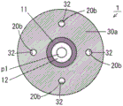
Fig. 3 is a schematic cross-sectional view showing a resin pipe connecting device of a second embodiment. Fig. 4 isbase:Sub>A sectional view taken along linebase:Sub>A-base:Sub>A of the resin pipe connection device of fig. 3. The resin pipe connection device 1 of fig. 3 differs from the resin pipe connection device 1 of fig. 2 in the following respects.
The end surface 30a of the metal sleeve 30 and the end surface 11a of the metal pipe 11 are formed on the same plane. One or more recesses 32 are provided in the end surface 30a of the metal sleeve 30. In the present embodiment, as shown in fig. 4, the recess 32 has an annular shape surrounding the resin pipe 10.
As shown in fig. 3, the resin expansion portion 20 includes an end surface covering portion 20a and an insertion portion 20b. The end surface coating portion 20a extends radially outward from the resin layer 12 and is formed on the end surface 11a of the metal pipe 11 and the end surface 30a of the metal sleeve 30. Thus, the end surface coating portion 20a has a thickness t2 larger than the thickness t1 of the resin layer 12 in the radial direction. The end surface coating portion 20a has a sealing surface 21.
The fitting portion 20b is formed to extend rearward from the outer peripheral portion of the end surface covering portion 20 a. The fitting portion 20b is formed integrally with the end surface covering portion 20 a. In the present embodiment, as shown in fig. 4, the fitting portion 20b has a circular cross section corresponding to the recess 32. Thus, the fitting portion 20b has a cylindrical shape. As shown in fig. 3, the outer side surface 23 of the end surface-coated portion 20a extends in the axial direction from the outer edge of the seal surface 21 to the rear end surface 22b of the fitting portion 20b. The fitting portion 20b is fitted into the recess 32. Since the fitting portion 20b is fitted into the recess 32, the maximum length L1 of the contact region 23c in the outer side surface 23 of the resin expanded portion 20 corresponds to the distance from the end surface 31 of the metal sleeve 30 to the bottom surface of the recess 32 (the depth of the recess 32) in the axial direction. The resin expansion portion 20 in the present embodiment is formed by, for example, ultrasonic processing.
In the resin pipe connecting device 1 of the second embodiment, the maximum length L1 of the contact region 23c of the resin expansion portion 20 is longer than the thickness t1 of the resin layer 12. In this case, since the axial length of the resin expansion portion 20 is large, the resin expansion portion 20 is not easily broken even if a torque is applied to the resin expansion portion 20. Further, since the fitting portion 20b of the expanded resin portion 20 is fitted into the recess 32 of the metal sleeve 30, the outer surface 23 of the expanded resin portion 20 is held by the metal sleeve 30. In this case, since a large frictional force acts between the metal sleeve 30 and the contact region 23c of the outer surface 23 of the fitting portion 20b, the resin expansion portion 20 can be firmly fixed to the metal sleeve 30. Thereby, the distortion of the resin pipe 10 can be suppressed. Further, since the outer side surface 23 of the resin expanded portion 20 is held by the metal sleeve 30, even if a compressive force in the axial direction is applied to the resin expanded portion 20, the seal surface 21 is prevented from expanding outward in the radial direction. As a result, the resin tube 10 and the resin expansion portion 20 can be prevented from being damaged.
Further, the opening area of the opening 24 of the resin expansion 20 is larger than the cross-sectional area of the flow passage hole 220 of the sleeve 200. Thus, as in the first embodiment, the opening 24 of the resin expansion portion 20 can be prevented from being closed, and the sealing surface 21 of the resin expansion portion 20 can be prevented from being damaged when the resin pipe connection device 1 is removed.
The configuration of the recess 32 of the metal sleeve 30 and the fitting portion 20b of the resin expansion portion 20 is not limited to the configuration of fig. 4. Fig. 5 is a cross-sectional view showing another example of the configuration of the recess 32 of the metal sleeve 30 and the fitting portion 20b of the resin expansion portion 20. Fig. 6 is a cross-sectional view showing still another example of the configuration of the recess 32 of the metal sleeve 30 and the fitting portion 20b of the resin expansion portion 20.
In the example of fig. 5, a plurality of recesses 32 are formed in the end surface 31 of the metal sleeve 30. The resin expansion portion 20 includes a plurality of insertion portions 20b that can be inserted into the plurality of concave portions 32. The plurality of concave portions 32 and the plurality of fitting portions 20b may be provided at a plurality of positions that are axisymmetrical about the axial center of the resin pipe 10, or may be provided at any plurality of positions that are not axisymmetrical. The plurality of recessed portions 32 and the plurality of fitting portions 20b may be provided at equal intervals or at different intervals. The cross-sectional shape of each recess 32 may be circular, polygonal, elliptical, or other shape.
In the example of fig. 6, one recess 32 is formed in the end surface 31 of the metal sleeve 30. The resin expansion portion 20 includes one fitting portion 20b that can be fitted into the recess 32. The cross-sectional shape of the recess 32 may be circular, polygonal, elliptical, or other shape.
In the example of fig. 5 and 6, the same effect as the example of fig. 4 can be obtained, and the rotation of the resin expansion portion 20 with respect to the metal sleeve 30 can be reliably prevented.
(4) Third embodiment
Fig. 7 is a schematic cross-sectional view showing a resin pipe connecting device of a third embodiment. The resin pipe connecting device 1 of fig. 7 differs from the resin pipe connecting device 1 of fig. 2 in the following respects.
The resin pipe connecting device 1 includes a resin sealing material 40 instead of the resin expansion 20. The resin sealing material 40 is, for example, a gasket. The resin sealing material 40 is formed separately from the resin layer 12, for example, from PEEK (polyether ether ketone). The resin sealing material 40 may be formed of another resin such as a fluororesin. In the present embodiment, the resin sealing material 40 is formed in a cylindrical shape having a front end surface, a rear end surface, an outer peripheral surface, and an inner peripheral surface. Thereby, a through-hole h1 extending in the axial direction is formed in the resin sealing material 40. The shape of the resin sealing material 40 is not limited to a cylindrical shape, and may be other shapes such as a square cylindrical shape.
The resin sealing material 40 has a sealing surface 41 on the front end surface and an outer peripheral surface 43 on the outer peripheral surface. The outer side surface 43 is formed to extend from the outer edge of the seal surface 41 to the outer edge of the rear end surface in the axial direction. The inner peripheral surface 44 is formed to extend from the inner edge of the seal surface 41 to the inner edge of the rear end surface in the axial direction. In this case, the resin sealing material 40 has a length L2 in the axial direction.
The resin layer 12 formed on the inner peripheral surface of the metal pipe 11 includes a portion protruding forward from the end surface 11a of the metal pipe 11. Hereinafter, the portion of the resin layer 12 protruding from the end surface 11a of the metal pipe 11 is referred to as a resin layer protruding portion 13. The resin layer protrusion 13 has a length L3 smaller than the length L2 of the resin sealing material 40. The resin layer protrusion 13 is inserted into the through hole h1 of the resin sealing material 40. Thereby, the rear end surface of the resin sealing material 40 comes into contact with the end surface 11a of the metal pipe 11.
At this time, since the length L2 of the resin seal material 40 is greater than the length L3 of the resin layer protrusion 13 of the resin pipe 10, the seal surface 41 of the resin seal material 40 protrudes forward in the axial direction than the end surface of the resin layer protrusion 13. Thereby, the opening 45 communicating with the first flow path p1 of the resin pipe 10 is formed in the sealing surface 41. The opening area of the opening 45 corresponds to the cross-sectional area of the through-hole h1. In the present embodiment, the opening area of the opening 45 is larger than the cross-sectional area of the flow path hole 220 of the sleeve 200 of fig. 1.
The outer peripheral surface of the resin layer protrusion 13 and the inner peripheral surface of the resin sealing material 40 are joined by thermal welding. The outer peripheral surface of the resin layer protrusion 13 and the inner peripheral surface of the resin sealing material 40 may be bonded by an adhesive or the like.
The metal sleeve 30 is formed to cover the outer peripheral surface of the metal pipe 11 and the outer surface 43 of the resin sealing material 40. An end face 30a is formed at the distal end of the metal sleeve 30. The sealing surface 41 of the resin sealing material 40 protrudes forward of the end surface 30a of the metal sleeve 30 in the axial direction. The region where the outer surface 43 of the resin sealing material 40 and the metal sleeve 30 contact each other is referred to as a contact region 43c. The maximum length L1 in the axial direction of the contact region 43c is larger than the thickness t1 of the resin layer 12.
In the resin pipe connecting device 1 of the third embodiment, the resin layer 12 and the resin sealing material 40 of the resin pipe 10 are formed of a resin material. Thereby, the resin layer 12 of the resin tube 10 and the resin sealing material 40 are firmly fixed by thermal welding. Also, the maximum length L1 of the contact region 43c is greater than the thickness t1 of the resin layer 12. In this case, since the length of the resin sealing material 40 in the axial direction is large, the resin sealing material 40 is not easily broken even if a torque is applied to the resin sealing material 40.
Further, since a large frictional force acts between the metal sleeve 30 and the contact region 43c on the outer surface 43 of the resin seal material 40, the resin seal material 40 can be firmly fixed to the metal sleeve 30. Thereby, the resin pipe 10 can be suppressed from being twisted. Further, since the outer side surface 43 of the resin seal material 40 is held by the metal sleeve 30, even if a compressive force in the axial direction is applied to the resin seal material 40, the seal surface 41 is prevented from spreading outward in the radial direction. Further, since the resin sealing material 40 is formed in a cylindrical shape, the durability of the resin sealing material 40 can be improved. As a result, the resin tube 10 can be prevented from being damaged.
The opening area of the opening 45 of the resin sealing material 40 is larger than the cross-sectional area of the flow passage hole 220 of the sleeve 200. As a result, as in the first embodiment, the opening 45 of the resin sealing material 40 can be prevented from being closed, and the sealing surface 41 of the resin sealing material 40 can be prevented from being damaged when the resin pipe connecting device 1 is removed.
Then, the resin layer protrusion 13 of the resin layer 12 of the resin tube 10 is inserted into the through-hole h1 of the resin sealing material 40, and the inner circumferential surface 44 of the resin sealing material 40 is joined to the outer circumferential surface of the resin layer protrusion 13 by thermal welding. In this case, the resin pipe connecting device 1 can be easily manufactured.
(5) Form of the composition
It will be understood by those skilled in the art that the above-described exemplary embodiments are specific examples of the following forms.
A resin pipe connecting device according to (first) aspect is connectable to a member to be connected having a contact surface with a flow passage hole formed therein, and includes:
a resin pipe including a metal pipe, and including a resin layer formed on an inner circumferential surface of the metal pipe, and including a first flow path surrounded by the resin layer;
a resin expanded portion formed integrally with the resin tube from the same material as the resin tube, the resin expanded portion being provided so as to protrude from an end of the resin layer in an axial direction and to protrude further outward than the metal tube in a radial direction of the resin tube; and
a metal sleeve formed to cover an outer peripheral surface of the metal pipe and an outer side surface of the resin expansion portion,
the resin expansion portion may include a seal surface contactable with the contact surface, and a second flow path communicating with the first flow path of the resin pipe and opening in the seal surface,
the seal surface protrudes further in the axial direction than an end surface of the metal sleeve,
in the outer side surface, a maximum length of a contact area of the resin expanded portion and the metal sleeve in the axial direction is larger than a thickness of the resin layer in the radial direction.
According to the resin pipe connecting device described in the first aspect, the resin expanded portion formed integrally with the resin layer of the resin pipe is provided so as to protrude outward beyond the metal pipe. The outer peripheral surface of the metal pipe and the outer side surface of the resin expanded portion are covered with a metal sleeve. When the resin pipe is connected to the member to be connected, a torque is applied to the metal sleeve, and the sealing surface of the resin expansion portion is pressed against the contact surface of the member to be connected. Thereby, the contact surface of the member to be connected and the sealing surface of the resin expansion portion are sealed in a state where the opening of the second flow path of the resin expansion portion communicates with the flow path hole of the member to be connected.
According to the structure, the maximum length of the contact area of the resin expanded portion and the metal sleeve in the axial direction is larger than the thickness of the resin layer in the radial direction. In this case, since the axial length of the resin spreading portion is large, the resin spreading portion is not easily broken even if torque is applied to the resin spreading portion. Further, when a torque is applied to the metal sleeve, a large frictional force acts between the resin expanded portion and the metal sleeve, so that the resin expanded portion can be firmly held with respect to the metal sleeve resin. Thus, the resin tube can be prevented from being twisted. Further, since the outer side surface of the resin expanded portion is held by the metal sleeve, even if a compressive force in the axial direction is applied to the resin expanded portion, the seal surface can be prevented from expanding outward in the radial direction. As a result, breakage of the resin tube can be prevented.
(second item) in the resin pipe connecting device according to the first item, the end surface of the metal sleeve may be positioned between the seal surface and an end surface of the metal pipe in the axial direction, the outer side surface of the resin expansion portion may extend to the end surface of the metal pipe in the axial direction,
in the outer side surface, the maximum length of the contact region of the resin expanded portion and the metal sleeve corresponds to a distance between the end surface of the metal sleeve and the end surface of the metal pipe in the axial direction.
According to the resin pipe connection device described in the second aspect, since the length of the resin expansion portion protruding further than the end surface of the metal pipe in the axial direction can be increased, the durability of the resin expansion portion can be improved.
(third item) in the resin pipe connecting device according to the second item
The resin expansion portion is formed in a columnar shape including one end face, the other end face, and the outer side face,
the one end surface of the columnar shape is the seal surface, and the other end surface of the columnar shape is in contact with the end surface of the metal pipe in the axial direction.
According to the resin pipe connecting device of the third aspect, the resin expanded portion has a columnar shape, and thus the durability of the resin expanded portion can be further improved.
(fourth) the resin pipe connecting device according to the first aspect, wherein
The end surface of the metal sleeve and the end surface of the metal pipe are formed on the same plane,
the end face of the metal sleeve includes a recess,
the resin expansion portion includes:
an end surface coating portion formed on the end surface of the metal pipe and the end surface of the metal sleeve so as to protrude outward in the radial direction from the metal pipe; and
an insertion portion that is integrally formed with the end surface covering portion, includes the outer side surface, and is inserted into the recess.
According to the resin pipe connecting device described in the fourth aspect, since the fitting portion of the resin expanded portion is fitted into the recess portion of the metal sleeve, the resin expanded portion can be reliably held by the metal sleeve. Thus, when torque is applied to the metal sleeve, twisting of the resin pipe can be suppressed. As a result, breakage of the resin tube can be prevented.
(fifth) the resin pipe connecting device according to any one of the first to fourth aspects, wherein
The area of the opening of the second flow path in the sealing surface of the resin expansion portion is larger than the cross-sectional area of the first flow path of the resin pipe.
According to the resin pipe connecting device described in the fifth aspect, when the seal surface of the resin expansion portion is pressed against the contact surface of the connected member, the second flow path of the resin expansion portion can be prevented from being clogged.
(sixth) another aspect of the resin pipe connecting device connectable to a member to be connected having a contact surface with a passage hole formed therein, includes:
a resin pipe including a metal pipe, a resin layer formed on an inner peripheral surface of the metal pipe and protruding in an axial direction from an end surface of the metal pipe, and a flow path surrounded by the resin layer;
a resin sealing material bonded to the resin layer so as to cover an outer peripheral surface of a portion of the resin layer protruding from the metal pipe; and
a metal sleeve formed to cover an outer peripheral surface of the metal pipe and an outer side surface of the resin sealing material,
the resin sealing material may include a sealing surface contactable with the contact surface, and an opening portion communicating with the flow path of the resin pipe,
the seal surface protrudes further in the axial direction than an end surface of the metal sleeve,
in the outer side surface, a maximum length of a contact region of the resin seal material and the metal sleeve in the axial direction is larger than a thickness of the resin layer in a radial direction.
According to the resin pipe connecting device described in the sixth aspect, the resin sealing material is bonded to the outer peripheral surface of the portion of the resin layer of the resin pipe that protrudes from the metal pipe. The outer peripheral surface of the metal pipe and the outer side surface of the resin sealing material are covered with a metal sleeve. When the resin pipe is connected to the member to be connected, a torque is applied to the metal sleeve, and the sealing surface of the resin sealing material is pressed against the contact surface of the member to be connected. In this way, the gap between the contact surface of the member to be connected and the sealing surface of the resin sealing material is sealed in a state where the opening of the resin sealing material is in communication with the flow path hole of the member to be connected.
According to this configuration, since the resin layer of the resin tube and the resin sealing material are formed of resin, the resin sealing material can be firmly joined to the resin layer of the resin tube. Further, the maximum length of the contact region between the resin seal material and the metal sleeve in the axial direction is larger than the thickness of the resin layer in the radial direction. In this case, since the length of the resin seal material in the axial direction is large, the resin seal material is less likely to be broken even if torque is applied to the resin seal material. Further, when a torque is applied to the metal sleeve, a large frictional force acts between the resin seal material and the metal sleeve, so that the outer surface of the resin seal material can be firmly held by the metal sleeve. Thus, the resin tube can be prevented from being twisted. Further, since the outer side surface of the resin expanded portion is held by the metal sleeve, even if a compressive force in the axial direction is applied to the resin expanded portion, the seal surface can be prevented from expanding outward in the radial direction. As a result, breakage of the resin tube can be prevented.
(seventh) the resin pipe connecting device according to the sixth aspect
The resin sealing material is joined to the outer peripheral surface of the resin layer by welding.
According to the resin pipe connecting device of the seventh aspect, the resin sealing material can be more firmly joined to the outer peripheral surface of the resin layer.
(eighth item) the resin pipe connecting device according to the sixth or seventh item
The area of the opening in the sealing surface of the resin sealing material is larger than the cross-sectional area of the flow path of the resin pipe.
According to the resin pipe connecting device of the eighth aspect, the opening of the resin sealing material can be prevented from being closed when the sealing surface of the resin expansion portion is pressed against the contact surface of the connected member.
(ninth) in the resin pipe connecting device according to any one of the sixth to eighth aspects, the resin sealing material may include a through-hole extending in the axial direction,
a portion of the resin layer protruding in the axial direction is inserted into the through-hole of the resin sealing material, and an inner peripheral surface of the resin sealing material is joined to an outer peripheral surface of the resin layer,
the sealing surface of the resin sealing material protrudes in the axial direction beyond an end surface of the resin layer, thereby forming the opening in the sealing surface.
According to the resin pipe connecting device described in the ninth aspect, the resin pipe connecting device can be easily manufactured by inserting the protruding portion of the resin layer of the resin pipe into the through hole of the resin sealing material and joining the inner peripheral surface of the resin sealing material to the outer peripheral surface of the resin layer.
Claims (9)
1. A resin pipe connecting device connectable to a member to be connected having a flow path hole and formed with a contact surface, the resin pipe connecting device comprising:
a resin pipe including a metal pipe, and including a resin layer formed on an inner circumferential surface of the metal pipe, and including a first flow path surrounded by the resin layer;
a resin expanded portion integrally formed with the resin tube from the same material as the resin tube, the resin expanded portion being provided so as to protrude from an end of the resin layer in an axial direction and to protrude further outward than the metal tube in a radial direction of the resin tube; and
a metal sleeve formed to cover an outer peripheral surface of the metal pipe and an outer side surface of the resin expansion portion,
the resin expansion portion includes a seal surface contactable with the contact surface, and includes a second flow path communicating with the first flow path of the resin pipe and opening in the seal surface,
the seal surface protrudes further in the axial direction than an end surface of the metal sleeve,
in the outer side surface, a maximum length of a contact region of the resin expanded portion and the metal sleeve in the axial direction is larger than a thickness of the resin layer in the radial direction.
2. The resin pipe connection device according to claim 1, wherein
The end surface of the metal sleeve is located between the seal surface and an end surface of the metal pipe in the axial direction, the outer side surface of the resin expansion portion extends to the end surface of the metal pipe in the axial direction,
in the outer side surface, the maximum length of the resin expanded portion, the metal sleeve, and the contact region corresponds to a distance between the end surface of the metal sleeve and the end surface of the metal pipe in the axial direction.
3. The resin pipe connection device according to claim 2, wherein
The resin expansion portion is formed in a columnar shape including one end surface, the other end surface, and the outer side surface,
the one end surface of the columnar shape is the seal surface, and the other end surface of the columnar shape is in contact with the end surface of the metal pipe in the axial direction.
4. The resin pipe connection device according to claim 1, wherein
An end surface of the metal sleeve is formed coplanar with an end surface of the metal pipe,
the end face of the metal sleeve includes a recess,
the resin expansion portion includes:
an end surface coating portion formed on the end surface of the metal pipe and the end surface of the metal sleeve so as to protrude outward in the radial direction from the metal pipe; and
an insertion portion that is integrally formed with the end surface covering portion, includes the outer side surface, and is inserted into the recess.
5. The resin pipe connection device according to claim 1, wherein an area of an opening of the second flow path in the sealing surface of the resin expansion portion is larger than a cross-sectional area of the first flow path of the resin pipe.
6. A resin pipe connecting device connectable to a member to be connected having a flow path hole and formed with a contact surface, the resin pipe connecting device comprising:
a resin pipe including a metal pipe, a resin layer formed on an inner peripheral surface of the metal pipe and protruding in an axial direction from an end surface of the metal pipe, and a flow path surrounded by the resin layer;
a resin sealing material bonded to the resin layer so as to cover an outer peripheral surface of a portion of the resin layer protruding from the metal pipe; and
a metal sleeve formed to cover an outer peripheral surface of the metal pipe and an outer side surface of the resin sealing material,
the resin sealing material includes a sealing surface contactable with the contact surface and an opening portion communicating with the flow path of the resin pipe,
the seal surface protrudes further in the axial direction than an end surface of the metal sleeve,
the maximum length of a contact region between the resin seal material and the metal sleeve in the axial direction is greater than the thickness of the resin layer in the radial direction.
7. The resin pipe connecting device according to claim 6, wherein the resin sealing material is joined to the outer peripheral surface of the resin layer by welding.
8. The resin pipe connection device according to claim 6, wherein an area of the opening in the sealing surface of the resin sealing material is larger than a cross-sectional area of the flow path of the resin pipe.
9. The resin pipe connection device according to claim 6, wherein
The resin seal material includes a through-hole extending in the axial direction,
a portion of the resin layer protruding in the axial direction is inserted into the through hole of the resin sealing material, and an inner peripheral surface of the resin sealing material is joined to an outer peripheral surface of the resin layer,
the sealing surface of the resin sealing material protrudes in the axial direction beyond an end surface of the resin layer, thereby forming the opening in the sealing surface.
Applications Claiming Priority (3)
| Application Number | Priority Date | Filing Date | Title |
|---|---|---|---|
| JP2020-100455 | 2020-06-09 | ||
| JP2020100455 | 2020-06-09 | ||
| PCT/JP2021/008010 WO2021250948A1 (en) | 2020-06-09 | 2021-03-02 | Resin tube connection device |
Publications (1)
| Publication Number | Publication Date |
|---|---|
| CN115698704A true CN115698704A (en) | 2023-02-03 |
Family
ID=78847186
Family Applications (1)
| Application Number | Title | Priority Date | Filing Date |
|---|---|---|---|
| CN202180040432.3A Pending CN115698704A (en) | 2020-06-09 | 2021-03-02 | Resin pipe connecting device |
Country Status (4)
| Country | Link |
|---|---|
| US (1) | US20230272870A1 (en) |
| JP (1) | JPWO2021250948A1 (en) |
| CN (1) | CN115698704A (en) |
| WO (1) | WO2021250948A1 (en) |
Family Cites Families (6)
| Publication number | Priority date | Publication date | Assignee | Title |
|---|---|---|---|---|
| DE102009022368C5 (en) * | 2009-05-22 | 2020-12-17 | Dionex Softron Gmbh | Connector unit and connection system for connecting capillaries, especially for high-performance liquid chromatography |
| EP2516912B1 (en) * | 2009-12-21 | 2015-04-08 | Agilent Technologies, Inc. | Fitting element with front side seal |
| EP2603792B1 (en) * | 2010-08-10 | 2019-09-25 | Idex Health&Science LLC | Biocompatible tubing for liquid chromatography systems |
| DE102012110991B4 (en) * | 2012-11-15 | 2017-01-05 | Dionex Softron Gmbh | Plug unit and connection system for connecting capillaries, in particular for high performance liquid chromatography |
| WO2016065334A1 (en) * | 2014-10-23 | 2016-04-28 | Idex Health & Science Llc | Face-sealing fluidic connection system |
| EP3163298B1 (en) * | 2015-10-30 | 2023-12-27 | Dionex Softron GmbH | Capillary tube connection |
-
2021
- 2021-03-02 US US18/007,805 patent/US20230272870A1/en active Pending
- 2021-03-02 JP JP2022530026A patent/JPWO2021250948A1/ja active Pending
- 2021-03-02 WO PCT/JP2021/008010 patent/WO2021250948A1/en active Application Filing
- 2021-03-02 CN CN202180040432.3A patent/CN115698704A/en active Pending
Also Published As
| Publication number | Publication date |
|---|---|
| JPWO2021250948A1 (en) | 2021-12-16 |
| WO2021250948A1 (en) | 2021-12-16 |
| US20230272870A1 (en) | 2023-08-31 |
Similar Documents
| Publication | Publication Date | Title |
|---|---|---|
| US9448210B2 (en) | Plug unit and connection system for connecting capillary tubes, especially for high-performance liquid chromatography | |
| US9945501B2 (en) | Plug unit and connection system for connecting capillary tubes | |
| JP5755704B2 (en) | Plug unit and connection system for connecting capillaries, especially for high performance liquid chromatography | |
| US4671545A (en) | Female-type coupling nipple | |
| JP5777267B2 (en) | Maintenance-free fluid fittings | |
| EP3118503B1 (en) | Low carryover high pressure fluidic fitting | |
| US10094494B2 (en) | Ferrule with features for softening ferrule crush and related methods | |
| KR20050057406A (en) | Tube fitting with tube gripping ring and sealant | |
| US11714067B2 (en) | Capillary tube connection | |
| EP2935962B1 (en) | Fluidic coupling seal | |
| EP1602870A1 (en) | Tube to hose coupling | |
| CN110036291B (en) | Fluid fitting with integrated face seal | |
| US20070013189A1 (en) | Sealing fitting for stainless steel tubing | |
| JP6480375B2 (en) | Pressure sensor | |
| CN115698704A (en) | Resin pipe connecting device | |
| US7537244B2 (en) | Fluid fitting assembly | |
| JP2010164089A (en) | Pipe connection structure | |
| JP2007170658A (en) | Pipe joint | |
| US9172150B2 (en) | Component composite between two components used for current conduction and method for manufacturing a component composite | |
| CN112585390B (en) | Joining method, pipe joint, and method for forming joining structure | |
| JP5538833B2 (en) | Pipe fitting | |
| CN207830772U (en) | Pipe connects | |
| JP2020094600A (en) | Pipe joint | |
| JPH1194166A (en) | Fitting and hose with fitting | |
| JPH0596686U (en) | Pipe connection device |
Legal Events
| Date | Code | Title | Description |
|---|---|---|---|
| PB01 | Publication | ||
| PB01 | Publication | ||
| SE01 | Entry into force of request for substantive examination | ||
| SE01 | Entry into force of request for substantive examination |