CN115683062B - Territorial space planning detection analysis system - Google Patents
Territorial space planning detection analysis system Download PDFInfo
- Publication number
- CN115683062B CN115683062B CN202310006137.7A CN202310006137A CN115683062B CN 115683062 B CN115683062 B CN 115683062B CN 202310006137 A CN202310006137 A CN 202310006137A CN 115683062 B CN115683062 B CN 115683062B
- Authority
- CN
- China
- Prior art keywords
- aerial vehicle
- unmanned aerial
- image
- flight
- target object
- Prior art date
- Legal status (The legal status is an assumption and is not a legal conclusion. Google has not performed a legal analysis and makes no representation as to the accuracy of the status listed.)
- Active
Links
Images


Abstract
The invention relates to the technical field of national space planning, in particular to a detection and analysis system for the national space planning, which is provided with an unmanned aerial vehicle set and a data processing module, controls a first unmanned aerial vehicle to shoot a surveying and mapping area at a higher height, determines a target object profile according to the difference of chromatic values of image slices of a shot second image, determines track points of a flight track of the second unmanned aerial vehicle in the surveying and mapping area according to the distance of a connecting line between the central points of the target object profile, adjusts flight parameters of the second unmanned aerial vehicle when the second unmanned aerial vehicle passes through the track points according to the area of the target object profile, analyzes a second image obtained by shooting the target object at each track point according to an image acquisition unit of the second unmanned aerial vehicle, corrects the flight parameters of the second unmanned aerial vehicle and the shooting parameters of the image acquisition unit according to an analysis result, avoids missing key characteristic surveying and mapping objects, and improves the efficiency and accuracy of surveying and mapping.
Description
Technical Field
The invention relates to the technical field of territorial space planning, in particular to a territorial space planning, detection and analysis system.
Background
The territorial space planning is the basic basis of sustainable development and various construction activities, the problems existing in the past planning are solved by taking one picture as a guide, the ecological civilized construction concept of a new era is realized, the territorial space planning method is a great change of the development thinking and the development mode of the territorial space in China, and the territorial space planning method has great significance for promoting scientific development and accelerating the change of the economic development mode and has profound significance for accurately constructing one picture of the territorial space planning.
Chinese patent publication No.: CN113920261A, this invention has disclosed unmanned aerial vehicle model building system and operation method of taking photo by plane of national soil space planning, involve the space planning technical field; the method aims to solve the problem that the landform and the landform cannot be directly and completely reflected during the territorial space planning; the system comprises a control module, a wireless communication module, an aerial photography measurement module, a differential GPS module, a three-dimensional modeling module and a storage module. According to the invention, the rotating connecting column is sleeved in the hollow circular ring, the unmanned aerial vehicle device and the shooting measuring device are bound together, the bearing connecting plate is always kept in a parallel state with the ground under the gravity of the bearing connecting block, the panoramic camera and the laser range finder, and the state of the bearing connecting plate is not influenced by the shaking, steering and the like of the unmanned aerial vehicle device in the flight process, so that the stability and accuracy of the panoramic camera and the laser range finder in shooting and measuring the regional landform are ensured.
However, the prior art has the following problems:
in prior art, when surveying and mapping through unmanned aerial vehicle, adopt single unmanned aerial vehicle survey and mapping, efficiency is lower, need continuous adjustment unmanned aerial vehicle's orbit, make a round trip to search for the characteristic region that awaits measuring to omission appears easily, do not consider to set up the position that piloting unmanned aerial vehicle carries out rough survey and mapping in order to confirm the characteristic region at higher flying height, and then automatic planning carries out the orbit and the flight parameter of the unmanned aerial vehicle of careful survey and mapping at lower flying height, in order to improve the quality of plotting efficiency and survey and mapping image.
Disclosure of Invention
In order to solve the problems that the efficiency is low due to the fact that a single unmanned aerial vehicle is adopted for surveying and mapping, the track of the unmanned aerial vehicle needs to be continuously adjusted, a characteristic region to be detected is searched back and forth, and omission easily occurs, the invention provides a device for planning, detecting and analyzing a homeland space, which comprises:
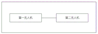
the unmanned aerial vehicle set comprises a first unmanned aerial vehicle and a second unmanned aerial vehicle, wherein the first unmanned aerial vehicle and the second unmanned aerial vehicle are respectively provided with a navigation positioning device for determining the geographic position coordinates of a target object in a surveying and mapping area and an image acquisition unit for shooting the target object;
the data processing module comprises a flight control unit, a target object contour determining unit, a path planning unit and a flight adjusting unit which are all connected with the unmanned aerial vehicle unit;
the flight control unit is used for controlling the first unmanned aerial vehicle and the second unmanned aerial vehicle to fly in an initial flight track, and controlling the flight altitude and the flight speed of the first unmanned aerial vehicle during flying to be higher than the flight altitude and the flight speed of the second unmanned aerial vehicle, so that the area of a region corresponding to a first image shot by the first unmanned aerial vehicle is larger than the area of a region corresponding to a second image shot by the second unmanned aerial vehicle;
the target object contour determining unit is used for determining a contour of a target object based on an image area surrounded by calibrated image slices in the first image and determining the geographic position coordinates of the contour of the target object, wherein the calibrated image slices are determined according to the chromaticity difference between each image slice in the first image and an adjacent image slice;
the path planning unit is used for determining track points, determining a planned flight track according to connecting lines of the track points, and controlling the second unmanned aerial vehicle to fly according to the planned flight track, wherein the track points are geographic position coordinates of the outlines of the targets or middle points of the connecting lines of the geographic position coordinates of the outlines of the targets;
the flight adjusting unit is used for adjusting the flight height and the flight speed of the second unmanned aerial vehicle when the second unmanned aerial vehicle flies to each track point based on the area parameters, analyzing the shot second image, obtaining an analysis result, correcting the flight parameters of the second unmanned aerial vehicle and the shooting parameters of the image acquisition unit under the first analysis result, and controlling the second unmanned aerial vehicle to shoot again at the corresponding track point to obtain a second image and analyze the second image;
controlling the second unmanned aerial vehicle to fly to the next track point for shooting under the second analysis result;
the area parameter comprises the area of the contour of the target object where the track point is located or the average value of the areas of the contours of the target objects on two sides of the connecting line where the track point is located.
Further, the target object contour determining unit determines the chroma value of each pixel point in each image slice, calculates the average value of chroma Δ C of each image slice according to formula (1),

in formula (1), ci represents a chrominance value of the ith pixel point in the image slice, and n represents the number of pixel points in the image slice, which is an integer greater than 1.
Further, the object contour determining unit calculates chromaticity differences Δ C 'between the current image slice and the adjacent image slices one by one, sets Δ C' =Δc- Δ Ce, where Δ C denotes a chromaticity average value of the current image slice, and Δ Ce denotes a chromaticity average value of the adjacent image slices of the current image slice, and compares the chromaticity differences Δ C 'with a preset standard chromaticity value difference amount contrast parameter Δ C0' to determine whether to calibrate the current image slice,
if the deltaC 'is more than or equal to the deltaC 0', the target object contour determining unit judges that the current image slice is calibrated;
if Δ C '<Δc0', the object contour determination unit determines not to calibrate the current image slice.
Further, the path planning unit determines a distance L of a connecting line of each geographic position coordinate, compares the distance L with a preset standard distance comparison parameter L0, and determines a track point of the planned flight trajectory according to a comparison result, wherein,
if L is larger than or equal to L0, the path planning unit determines that the geographic position coordinates of the two ends of the connecting line are used as track points;
if L is less than L0, the path planning unit determines the midpoint of the connecting line as a track point;
and the path planning unit connects the track points one by one to obtain the planned flight path.
Further, the flight adjusting unit determines an area S of a target profile where the track point is located or an area average value Δ S of target profiles at both ends of a connection line where the track point is located, compares the area S with a first area parameter S1 and a second area parameter S2 under a first condition, compares the area average value Δ S with the first area parameter S1 and the second area parameter S2 under a second condition, wherein,
the first condition is that the track point is in the contour of the target object;
and the second condition is that the track point is not in the contour of the target object.
Further, the flight adjusting unit determines an adjusting mode when the flight parameter of the second unmanned aerial vehicle is adjusted when the second unmanned aerial vehicle flies to the track point according to the comparison result under the first condition or the comparison result under the second condition, wherein,
the first adjustment mode is that the flying height of the second unmanned aerial vehicle is adjusted to a first flying height value according to a first flying height adjustment amount h1, and the flying speed of the second unmanned aerial vehicle is adjusted to a first flying speed value according to a first flying speed adjustment amount v 1;
the second adjustment mode is that the flying height of the second unmanned aerial vehicle is adjusted to a second flying height value according to a first flying height adjustment amount h2, and the flying speed of the second unmanned aerial vehicle is adjusted to a second flying speed value according to a first flying speed adjustment amount v2;
the third adjustment mode is that the flying height of the second unmanned aerial vehicle is adjusted to a third flying height value according to the first flying height adjustment amount h3, and the flying speed of the second unmanned aerial vehicle is adjusted to a third flying speed value according to the first flying speed adjustment amount v3;
the first adjustment mode needs to satisfy that S is more than or equal to S2 or delta S is more than or equal to S2, the second adjustment mode needs to satisfy that S is more than or equal to S1 and less than S2 or delta S is more than or equal to S2, and the third adjustment mode needs to satisfy that S is less than S1 or delta S is less than S1, h1 is more than h2 and more than h3, and v1 is more than v2 and more than v3.
Further, when the flight adjustment unit analyzes the second image, the method includes acquiring an image characteristic threshold K, wherein,
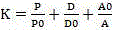
in the formula (2), P0 represents a preset standard pixel number contrast parameter, D0 represents a preset standard pixel depth contrast parameter, A0 represents a preset standard distortion contrast parameter, P represents the pixel number of the second image, D represents the pixel depth of the second image, and a represents the distortion of the second image.
Further, the flight adjusting unit compares an image characteristic threshold K corresponding to the second image with a preset standard image characteristic comparison threshold K0 to obtain an analysis result, wherein,
the first analysis result is that K is less than K0,
the second analysis result is that K is more than or equal to K0.
Further, the flight adjusting unit compares an image characteristic threshold K corresponding to the second image with a preset standard image characteristic comparison threshold K0 to obtain an analysis result, wherein,
the first analysis result is that K is less than K0, the flight adjusting unit corrects the flight parameters and the shooting parameters of the second unmanned aerial vehicle, wherein,
correcting the current flying height of the second unmanned aerial vehicle to a first flying height correction value according to the flying height correction value h'; correcting the current flying speed of the second unmanned aerial vehicle to a first flying speed correction value according to the flying speed correction value v';
adjusting the aperture of the second unmanned aerial vehicle to a first aperture adjustment value according to the aperture adjustment amount f;
adjusting the shutter of the second unmanned aerial vehicle to a first shutter adjustment value according to the shutter adjustment amount m;
and adjusting the sensitivity of the second unmanned aerial vehicle to a first sensitivity adjustment value according to a sensitivity adjustment amount i.
Further, the data processing module further comprises a mapping unit for screening images captured by the first drone and the second drone, wherein,
screening out and recording the second image with the analysis result being the second analysis result to the database.
Compared with the prior art, the unmanned aerial vehicle system is provided with the unmanned aerial vehicle set and the data processing module, the first unmanned aerial vehicle is controlled to fly to shoot a surveying and mapping area at a higher height, the target object outline is determined according to the difference of the colorimetric values of all image slices of the shot second image, the track point of the flight track of the second unmanned aerial vehicle in the surveying and mapping area is determined according to the distance of the connecting line between the central points of the target object outline, the flight parameters of the second unmanned aerial vehicle passing through the track point are adjusted according to the area of the target object outline, the second image obtained by shooting the target object at all track points through the image acquisition unit of the second unmanned aerial vehicle is analyzed, the flight parameters of the second unmanned aerial vehicle and the shooting parameters of the image acquisition unit are corrected according to the analysis result, omission of key feature surveying and mapping objects is avoided, and the efficiency and accuracy of surveying and mapping are improved.
Particularly, in the invention, the data processing module determines the area surrounded by the image slices with the chromaticity difference between the image slices and the adjacent image slices larger than the preset value as the profile of the target object, in the actual situation, the image acquisition unit shoots the mapping area to acquire the image, the chromaticity values of the pixel points of different types of objects in the image are different, therefore, the first unmanned aerial vehicle flies at a higher height to acquire the image of a larger area, the area with the difference with the surrounding environment can be determined according to the difference of the chromaticity average values of the adjacent image slices, the area is determined as the profile of the target object to determine the specific position of the specific characteristic mapping area, a basis is provided for determining the planning flight trajectory and adjusting the flight parameters in the subsequent mapping process, the omission of key characteristic mapping objects is avoided, and the mapping efficiency is improved.
In particular, in the invention, the data processing module determines track points of a planned flight trajectory according to the distance of a connecting line between the central points of the contour of the target object, in an actual situation, the corresponding position of the contour of the target object in the surveying and mapping area is determined according to a second image obtained by shooting the surveying and mapping area by a first unmanned machine, a basis is provided for determining the planned flight trajectory, the distance between the central points of the contour of the target object represents the distance between the target objects, when the distance between the target objects is large, the central points of the target object are required to be used as the track points, when the distance between the target objects is small, the midpoint position between the central points of the two target objects is used as the track points, and the two target objects are shot at the track points, so that the surveying and mapping efficiency is improved.
Particularly, in the invention, the data processing module adjusts the flight parameters of the second unmanned aerial vehicle according to the area of the outline of the target object, in an actual situation, when the area of the outline of the target object is large, the flight height of the second unmanned aerial vehicle can be increased to shoot the target object comprehensively, the flight speed of the second unmanned aerial vehicle is increased to improve the shooting efficiency of the target object, when the area of the target object is small, the flight height and the flight speed of the second unmanned aerial vehicle are reduced, the shooting efficiency and effect of images in surveying and mapping are ensured, and the surveying and mapping efficiency and accuracy are improved.
Particularly, in the invention, the data processing module corrects the flight parameters of the second unmanned aerial vehicle and the shooting parameters of the image acquisition unit of the second unmanned aerial vehicle according to the image characteristic threshold of the second image obtained by shooting the target object at each locus point by the second unmanned aerial vehicle, and in an actual situation, the image characteristic threshold of the image is obtained by calculating the pixel number, the pixel depth and the distortion degree of the image, so that the image characteristic threshold represents the imaging effect of the image, and the flight height and the flight speed of the second unmanned aerial vehicle are adjusted according to the imaging effect of the shot image after the imaging effect of the image represents the imaging effect of the image, so that the shooting parameters are matched with the shooting requirements during low-altitude flight or low-speed flight, a better shooting effect is obtained, the shooting effect of the image during surveying and mapping is further ensured, and the accuracy of surveying and mapping is ensured.
Drawings
FIG. 1 is a schematic structural diagram of a territorial space planning, detecting and analyzing system according to an embodiment of the invention;
FIG. 2 is a schematic view of an embodiment of the invention;
FIG. 3 is a block diagram of a data processing module according to an embodiment of the invention;
fig. 4 is a schematic diagram of the contour structure of the target object according to the embodiment of the invention.
Detailed Description
In order that the objects and advantages of the invention will be more clearly understood, the invention is further described in conjunction with the following examples; it should be understood that the specific embodiments described herein are merely illustrative of the invention and are not intended to limit the invention.
Preferred embodiments of the present invention are described below with reference to the accompanying drawings. It should be understood by those skilled in the art that these embodiments are only for explaining the technical principle of the present invention, and do not limit the scope of the present invention.
It should be noted that in the description of the present invention, the terms of direction or positional relationship indicated by the terms "upper", "lower", "left", "right", "inner", "outer", etc. are based on the directions or positional relationships shown in the drawings, which are only for convenience of description, and do not indicate or imply that the device or element must have a specific orientation, be constructed and operated in a specific orientation, and thus, should not be construed as limiting the present invention.
Furthermore, it should be noted that, in the description of the present invention, unless otherwise explicitly specified or limited, the terms "mounted," "connected," and "connected" are to be construed broadly, and may be, for example, fixedly connected, detachably connected, or integrally connected; can be mechanically or electrically connected; they may be connected directly or indirectly through intervening media, or they may be interconnected between two elements. The specific meanings of the above terms in the present invention can be understood by those skilled in the art according to specific situations.
Please refer to fig. 1, fig. 2, and fig. 3, which are schematic structural diagrams of a territorial space planning, detecting and analyzing system, an unmanned aerial vehicle set structural diagram, and a data processing module structural diagram according to an embodiment of the present invention, and the territorial space planning, detecting and analyzing system according to the present invention includes:
the unmanned aerial vehicle set comprises a first unmanned aerial vehicle and a second unmanned aerial vehicle, wherein the first unmanned aerial vehicle and the second unmanned aerial vehicle are respectively provided with a navigation positioning device for determining the geographic position coordinates of a target object in a surveying and mapping area and an image acquisition unit for shooting the target object;
the data processing module comprises a flight control unit, a target object contour determining unit, a path planning unit and a flight adjusting unit which are all connected with the unmanned aerial vehicle;
the flight control unit is used for controlling the first unmanned aerial vehicle and the second unmanned aerial vehicle to fly in an initial flight trajectory, and controlling the flight height and the flight speed of the first unmanned aerial vehicle during flying to be higher than the flight height and the flight speed of the second unmanned aerial vehicle, so that the area of a region corresponding to a first image shot by the first unmanned aerial vehicle is larger than the area of a region corresponding to a second image shot by the second unmanned aerial vehicle;
the target object contour determining unit is used for determining a target object contour based on an image area surrounded by a calibrated image slice in the first image and determining the geographic position coordinates of the target object contour, wherein the calibrated image slice is determined according to the chromaticity difference between each image slice in the first image and an adjacent image slice;
the path planning unit is used for determining track points, determining a planned flight track according to connecting lines of the track points, and controlling the second unmanned aerial vehicle to fly according to the planned flight track, wherein the track points are geographical position coordinates of the outlines of the targets or connecting line midpoints of the geographical position coordinates of the outlines of the targets;
the flight adjusting unit is used for adjusting the flight height and the flight speed of the second unmanned aerial vehicle when the second unmanned aerial vehicle flies to each track point based on the area parameters, analyzing the shot second image and obtaining an analysis result,
correcting the flight parameters of the second unmanned aerial vehicle and the shooting parameters of the image acquisition unit under the first analysis result, and controlling the second unmanned aerial vehicle to shoot again at the corresponding track point to obtain a second image and analyze the second image;
controlling the second unmanned aerial vehicle to fly to the next track point for shooting under the second analysis result;
the area parameter comprises the area of the contour of the target object where the track point is located or the average value of the areas of the contours of the target objects on two sides of the connecting line where the track point is located.
Specifically, the specific structure of the image acquisition unit is not limited, and the image acquisition unit can be a high-speed camera or an aerial camera, and only needs to meet the requirement of image acquisition in the process of rapid movement.
Specifically, the specific structure of the navigation positioning device is not limited in the present invention, and the navigation positioning device may be a GPS navigation positioning device, and the geographic position coordinates may be determined, which is not described herein again for the prior art.
Specifically, the specific form of the data processing module is not limited, and the data processing module only needs to complete the functions of data processing and data exchange, and in this embodiment, the data processing module may be an external computer, each unit therein may be a functional program capable of completing various functions in the computer, and for the connection mode between each module in the data processing module and the unmanned aerial vehicle set, this embodiment is not specifically limited, and only needs to be in communication connection with an image acquisition unit, a navigation positioning device and control systems of the first unmanned aerial vehicle and the second unmanned aerial vehicle set in the unmanned aerial vehicle set, so as to achieve the effects of acquiring images, acquiring navigation positioning information and controlling the first unmanned aerial vehicle and the second unmanned aerial vehicle.
Specifically, the target object contour determining unit determines the chroma value of each pixel point in each image slice, calculates the chroma average value deltaC of each image slice according to the formula (1),

in formula (1), ci represents a chrominance value of the ith pixel point in the image slice, and n represents the number of pixel points in the image slice, which is an integer greater than 1.
Specifically, as shown in fig. 4, the object contour determining unit calculates chromaticity difference Δ C ' between the current image slice and each adjacent image slice one by one, sets Δ C ' =Δc- Δ Ce, where Δ C represents a chromaticity average value of the current image slice, and Δ Ce represents a chromaticity average value of an adjacent image slice of the current image slice, and compares the chromaticity difference Δ C ' with a preset standard chromaticity value difference amount contrast parameter Δ C0', where Δ C0' > 0, to determine whether to calibrate the current image slice,
if the deltaC 'is more than or equal to the deltaC 0', the target object contour determining unit judges that the current image slice is calibrated;
if Δ C '<Δc0', the object contour determination unit determines not to calibrate the current image slice.
Specifically, in the invention, a data processing module determines a region surrounded by an image slice and adjacent image slices with the chromaticity difference larger than a preset value as a target object contour, in an actual situation, an image acquisition unit shoots the mapping region to obtain an image, wherein the chromaticity values of pixel points of different types of objects in the image are different, so that the image in a larger region is obtained by flying a higher altitude through a first unmanned aerial vehicle, the region with the difference from the surrounding environment can be determined according to the difference of the chromaticity average values of the adjacent image slices, the region is determined as the target object contour to determine the specific position of a specific characteristic mapping region, a basis is provided for determining a flight trajectory and adjusting flight parameters in the subsequent mapping process, omission of key characteristic mapping objects is avoided, and the mapping efficiency is improved.
Specifically, the path planning unit determines a distance L of a connecting line of each geographical position coordinate, compares the distance L with a preset standard distance comparison parameter L0, where L0 is greater than L0 and less than 50m, and determines a track point of the planned flight trajectory according to a comparison result, where,
if L is larger than or equal to L0, the path planning unit determines that the geographic position coordinates of the two ends of the connecting line are used as track points;
if L is less than L0, the path planning unit determines the middle point of the connecting line as a track point;
and the path planning unit connects the track points one by one to obtain the planned flight path.
Specifically, in the invention, the data processing module determines track points of a planned flight trajectory according to the distance of a connecting line between the central points of the contour of the target object, in an actual situation, the corresponding position of the contour of the target object in the surveying and mapping area is determined according to a second image obtained by shooting the surveying and mapping area by a first unmanned machine, a basis is provided for determining the planned flight trajectory, the distance between the central points of the contour of the target object represents the distance between the target objects, when the distance between the target objects is large, the central points of the target object are required to be used as the track points, when the distance between the target objects is small, the midpoint position between the central points of the two target objects is used as the track points, the two target objects are shot at the track points, and the surveying and mapping efficiency is improved.
Specifically, the flight adjusting unit determines the area S of the target object profile where the track point is located or the area average value deltaS of the target object profile at two ends of the connecting line where the track point is located, compares the area S with a first area parameter S1 and a second area parameter S2 under a first condition, compares the area average value deltaS with the first area parameter S1 and the second area parameter S2 under a second condition, and S1 is more than 0 and less than S2, wherein,
the first condition is that the track point is in the contour of the target object;
and the second condition is that the track point is not in the contour of the target object.
Specifically, the flight adjustment unit determines an adjustment mode when the flight parameter of the second unmanned aerial vehicle when the second unmanned aerial vehicle flies to the track point according to the comparison result under the first condition or the comparison result under the second condition, wherein,
the first adjustment mode is that the flying height of the second unmanned aerial vehicle is adjusted to a first flying height value according to a first flying height adjustment amount H1, H1 is set to be H1= H0+ H1, H0 represents the initial flying height of the second unmanned aerial vehicle, 100m & lth 0 & lt 500m, the flying speed of the second unmanned aerial vehicle is adjusted to a first flying speed value V1 according to a first flying speed adjustment amount V1, V1= V0+ V1 is set, V0 represents the initial flying speed of the second unmanned aerial vehicle, and 50km/H & ltv 0 & lt 200km/H;
the second adjustment mode is that the flying height of the second unmanned aerial vehicle is adjusted to a second flying height value H2 according to a first flying height adjustment amount H2, H2= H0+ H2 is set, the flying speed of the second unmanned aerial vehicle is adjusted to a second flying speed value V2 according to a first flying speed adjustment amount V2, and V2= V0+ V2 is set;
the third adjustment mode is that the flying height of the second unmanned aerial vehicle is adjusted to a third flying height value H3 according to the first flying height adjustment amount H3, H3= H0+ H3 is set, the flying speed of the second unmanned aerial vehicle is adjusted to a third flying speed value V3 according to the first flying speed adjustment amount V3, and V3= V0+ V3 is set;
the first adjustment mode needs to satisfy that S is more than or equal to S2 or delta S is more than or equal to S2, the second adjustment mode needs to satisfy that S is more than or equal to S1 and less than S2 or delta S is more than or equal to S2, the third adjustment mode needs to satisfy that S is more than or equal to S1 or delta S is less than or equal to S1 and less than S2 or delta S is less than or equal to S1 and less than S1, h1 is more than h2 and more than h3, h1 is more than or equal to 150m and less than 200m,100m is more than or equal to h2 and less than 150m,50m is more than or equal to h3 and less than 100m, v1 is more than or equal to v2 and more than v3, 40km/h is more than or equal to 40km/h and less than or equal to v1 and less than or equal to 60km/h,20km/h is more than or equal to v3 and less than or equal to 20km/h.
Specifically, in the invention, the data processing module adjusts the flight parameters of the second unmanned aerial vehicle according to the area of the outline of the target object, in an actual situation, when the area of the outline of the target object is large, the flight height of the second unmanned aerial vehicle can be increased to shoot the target object comprehensively, the flight speed of the second unmanned aerial vehicle is increased to improve the shooting efficiency of the target object, when the area of the target object is small, the flight height and the flight speed of the second unmanned aerial vehicle are reduced, the shooting efficiency and effect of images in mapping are ensured, and the mapping efficiency and accuracy are improved.
Specifically, the analyzing of the second image by the flight adjusting unit includes acquiring an image characteristic threshold K, wherein,
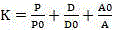
in formula (2), P0 represents a preset standard pixel number contrast parameter, P0 > 0, D0 represents a preset standard pixel depth contrast parameter, D0 > 0, A0 represents a preset standard distortion contrast parameter, A0 > 0, P represents the pixel number of the second image, D represents the pixel depth of the second image, and a represents the distortion of the second image.
Specifically, the flight adjustment unit compares an image characteristic threshold K corresponding to the second image with a preset standard image characteristic comparison threshold K0 to obtain an analysis result, wherein,
the first analysis result is that K is less than K0,
the second analysis result is that K is more than or equal to K0.
Specifically, the flight adjustment unit corrects the flight parameters and the shooting parameters of the second unmanned aerial vehicle, wherein,
correcting the current flying height of the second unmanned aerial vehicle to a first flying height correction value H ' according to a flying height correction value H ', setting H ' = H0e-H ', wherein H0e represents the current flying height of the second unmanned aerial vehicle, and 30m < H ' < 60m;
correcting the current flying speed of the second unmanned aerial vehicle to a first flying speed correction value V ' according to a flying speed correction value V ', setting V ' = V0e-V ', wherein V0e represents the current flying speed of the second unmanned aerial vehicle, and 5km/h < V ' < 20km/h;
adjusting the aperture of the second unmanned aerial vehicle to a first aperture adjustment value F according to an aperture adjustment amount F, setting F = F0-F, wherein F0 represents an initial aperture value of the second unmanned aerial vehicle, and 10 < F0 < 15,1 < F < 5;
adjusting the shutter of the second unmanned aerial vehicle to a first shutter adjustment value M according to a shutter adjustment amount M, setting M = M0-M, wherein M0 represents an initial shutter value of the second unmanned aerial vehicle, 1/1500s < M0 < 1/350s,1/6000s < M < 1/1500s;
and adjusting the sensitivity of the second unmanned aerial vehicle to a first sensitivity adjustment value I according to a sensitivity adjustment amount I, setting I = I0-I, wherein I0 represents a sensitivity initial value of the second unmanned aerial vehicle, and the value is 500 & lti 0 & lt 2000 and 100 & lti & lt 500.
Specifically, in the invention, the data processing module corrects the flight parameters of the second unmanned aerial vehicle and the shooting parameters of the image acquisition unit of the second unmanned aerial vehicle according to the image characteristic threshold of the second image obtained by shooting the target object at each locus point by the second unmanned aerial vehicle, and in an actual situation, the image characteristic threshold of the image is obtained by calculating the pixel number, the pixel depth and the distortion degree of the image, so that the image characteristic threshold represents the imaging effect of the image, and the flight height and the flight speed of the second unmanned aerial vehicle are adjusted according to the imaging effect of the shot image after the imaging effect of the image represents the imaging effect of the image, so that the shooting parameters are matched with the shooting requirements during low-altitude flight or low-speed flight, a better shooting effect is obtained, the shooting effect of the image during surveying and mapping is further ensured, and the accuracy of surveying and mapping is ensured.
In particular, the data processing module further comprises a mapping unit for screening images captured by the first drone and the second drone, wherein,
and screening out the second image with the analysis result being the second analysis result and recording the second image to the database.
So far, the technical solutions of the present invention have been described in connection with the preferred embodiments shown in the drawings, but it is easily understood by those skilled in the art that the scope of the present invention is obviously not limited to these specific embodiments. Equivalent changes or substitutions of related technical features can be made by those skilled in the art without departing from the principle of the invention, and the technical scheme after the changes or substitutions can be within the protection scope of the invention.
Claims (8)
1. A territorial space planning detection analysis system, characterized by, includes:
the unmanned aerial vehicle set comprises a first unmanned aerial vehicle and a second unmanned aerial vehicle, wherein the first unmanned aerial vehicle and the second unmanned aerial vehicle are respectively provided with a navigation positioning device for determining the geographic position coordinates of a target object in a surveying and mapping area and an image acquisition unit for shooting the target object;
the data processing module comprises a flight control unit, a target object contour determining unit, a path planning unit and a flight adjusting unit which are all connected with the unmanned aerial vehicle;
the flight control unit is used for controlling the first unmanned aerial vehicle and the second unmanned aerial vehicle to fly in an initial flight track, and controlling the flight altitude and the flight speed of the first unmanned aerial vehicle during flying to be higher than the flight altitude and the flight speed of the second unmanned aerial vehicle, so that the area of a region corresponding to a first image shot by the first unmanned aerial vehicle is larger than the area of a region corresponding to a second image shot by the second unmanned aerial vehicle;
the target object contour determining unit is used for determining a target object contour based on an image area surrounded by a calibrated image slice in the first image and determining the geographic position coordinates of the target object contour, wherein the calibrated image slice is determined according to the chromaticity difference between each image slice in the first image and an adjacent image slice;
the path planning unit is used for determining track points, determining a planned flight track according to connecting lines of the track points, and controlling the second unmanned aerial vehicle to fly according to the planned flight track, wherein the track points are geographical position coordinates of the outlines of the targets or connecting line midpoints of the geographical position coordinates of the outlines of the targets;
the flight adjusting unit is used for adjusting the flight height and the flight speed of the second unmanned aerial vehicle when the second unmanned aerial vehicle flies to each track point based on the area parameters, analyzing the shot second image and obtaining an analysis result,
correcting the flight parameters of the second unmanned aerial vehicle and the shooting parameters of the image acquisition unit under the first analysis result, and controlling the second unmanned aerial vehicle to shoot again at the corresponding track point to obtain a second image and analyze the second image;
controlling the second unmanned aerial vehicle to fly to the next track point for shooting under the second analysis result;
the area parameter comprises the area of the contour of the target object where the track point is located or the average value of the areas of the contours of the target objects on two sides of the connecting line where the track point is located;
the flight adjustment unit analyzes the second image, and comprises an image characteristic threshold value K,

in formula (1), P0 represents a preset standard pixel number contrast parameter, D0 represents a preset standard pixel depth contrast parameter, A0 represents a preset standard distortion contrast parameter, P represents the pixel number of the second image, D represents the pixel depth of the second image, and a represents the distortion of the second image;
the flight adjusting unit compares an image characteristic threshold value K corresponding to the second image with a preset standard image characteristic comparison threshold value K0 to obtain an analysis result, wherein,
the first analysis result is that K is less than K0;
the second analysis result is that K is more than or equal to K0.
2. The territorial space planning, detecting and analyzing system of claim 1 wherein the target object contour determining unit determines the chroma value of each pixel point in each image slice, calculates the average value of chroma Δ C of each image slice according to formula (2),

in formula (2), ci represents a chrominance value of the ith pixel point in the image slice, and n represents the number of pixel points in the image slice, which is an integer greater than 1.
3. The system for planning, detecting and analyzing a homeland space according to claim 2, wherein the object contour determining unit calculates chromaticity difference ac 'between the current image slice and each of the adjacent image slices one by one, sets ac' =ac-ac Δ Ce, Δ C representing a chromaticity mean value of the current image slice, Δ Ce representing a chromaticity mean value of the adjacent image slices of the current image slice, and compares the chromaticity difference ac 'with a preset standard chromaticity value difference amount comparison parameter ac 0' to determine whether to calibrate the current image slice, wherein,
if the deltaC 'is more than or equal to the deltaC 0', the target object contour determining unit judges that the current image slice is calibrated;
if Δ C '<Δc0', the object contour determination unit determines not to calibrate the current image slice.
4. The territorial space planning, detecting and analyzing system of claim 3 wherein the path planning unit determines a distance L of a connecting line of each of the geographic position coordinates, compares the distance L with a preset standard distance comparison parameter L0, and determines a trajectory point of the planned flight trajectory according to a comparison result, wherein,
if L is larger than or equal to L0, the path planning unit determines that the geographic position coordinates of the two ends of the connecting line are used as track points;
if L is less than L0, the path planning unit determines the middle point of the connecting line as a track point;
and the path planning unit connects the track points one by one to obtain the planned flight path.
5. The territorial space planning, detecting and analyzing system of claim 4, wherein the flight adjusting unit determines an area S of a target profile where a track point is located or an area average value Δ S of target profiles at two ends of a connecting line where the track point is located, compares the area S with a first area parameter S1 and a second area parameter S2 under a first condition, compares the area average value Δ S with the first area parameter S1 and the second area parameter S2 under a second condition, wherein,
the first condition is that the track point is in the contour of the target object;
and the second condition is that the track point is not in the contour of the target object.
6. The territorial space planning, detecting and analyzing system of claim 5, wherein the flight adjusting unit determines an adjusting mode for adjusting the flight parameters of the second unmanned aerial vehicle when the second unmanned aerial vehicle flies to the trajectory points according to the comparison result under the first condition or the comparison result under the second condition, wherein,
the first adjustment mode is that the flying height of the second unmanned aerial vehicle is adjusted to a first flying height value according to a first flying height adjustment amount h1, and the flying speed of the second unmanned aerial vehicle is adjusted to a first flying speed value according to a first flying speed adjustment amount v 1;
the second adjustment mode is that the flying height of the second unmanned aerial vehicle is adjusted to a second flying height value according to a first flying height adjustment amount h2, and the flying speed of the second unmanned aerial vehicle is adjusted to a second flying speed value according to a first flying speed adjustment amount v2;
the third adjustment mode is that the flying height of the second unmanned aerial vehicle is adjusted to a third flying height value according to the first flying height adjustment amount h3, and the flying speed of the second unmanned aerial vehicle is adjusted to a third flying speed value according to the first flying speed adjustment amount v3;
the first adjustment mode needs to satisfy that S is more than or equal to S2 or delta S is more than or equal to S2, the second adjustment mode needs to satisfy that S is more than or equal to S1 and less than S2 or delta S is more than or equal to S2, and the third adjustment mode needs to satisfy that S is less than S1 or delta S is less than S1, h1 is more than h2 and more than h3, and v1 is more than v2 and more than v3.
7. The territorial space planning, detecting and analyzing system of claim 6, wherein the flight adjusting unit modifies flight parameters and imaging parameters of the second UAV, wherein,
correcting the current flying height of the second unmanned aerial vehicle to a first flying height correction value according to the flying height correction value h'; correcting the current flying speed of the second unmanned aerial vehicle to a first flying speed correction value according to the flying speed correction value v';
adjusting the aperture of the second unmanned aerial vehicle to a first aperture adjustment value according to the aperture adjustment amount f;
adjusting the shutter of the second unmanned aerial vehicle to a first shutter adjustment value according to the shutter adjustment amount m;
and adjusting the sensitivity of the second unmanned aerial vehicle to a first sensitivity adjustment value according to a sensitivity adjustment amount i.
8. The territorial space planning detection analysis system of claim 7, wherein the data processing module further comprises a mapping unit for screening images taken by the first drone and the second drone, wherein,
and screening out the second image with the analysis result being the second analysis result and recording the second image to the database.
Priority Applications (1)
| Application Number | Priority Date | Filing Date | Title |
|---|---|---|---|
| CN202310006137.7A CN115683062B (en) | 2023-01-04 | 2023-01-04 | Territorial space planning detection analysis system |
Applications Claiming Priority (1)
| Application Number | Priority Date | Filing Date | Title |
|---|---|---|---|
| CN202310006137.7A CN115683062B (en) | 2023-01-04 | 2023-01-04 | Territorial space planning detection analysis system |
Publications (2)
| Publication Number | Publication Date |
|---|---|
| CN115683062A CN115683062A (en) | 2023-02-03 |
| CN115683062B true CN115683062B (en) | 2023-03-10 |
Family
ID=85057596
Family Applications (1)
| Application Number | Title | Priority Date | Filing Date |
|---|---|---|---|
| CN202310006137.7A Active CN115683062B (en) | 2023-01-04 | 2023-01-04 | Territorial space planning detection analysis system |
Country Status (1)
| Country | Link |
|---|---|
| CN (1) | CN115683062B (en) |
Families Citing this family (2)
| Publication number | Priority date | Publication date | Assignee | Title |
|---|---|---|---|---|
| CN115883969B (en) * | 2023-02-16 | 2023-05-05 | 北京万和汇通通信科技有限公司 | Unmanned aerial vehicle shooting method, unmanned aerial vehicle shooting device, unmanned aerial vehicle shooting equipment and unmanned aerial vehicle shooting medium |
| CN115995050B (en) * | 2023-03-22 | 2023-06-13 | 山东汇蓝环保科技有限公司 | Environment monitoring data processing system based on aerial photography |
Citations (5)
| Publication number | Priority date | Publication date | Assignee | Title |
|---|---|---|---|---|
| CN105203084A (en) * | 2015-07-02 | 2015-12-30 | 汤一平 | 3D panoramic vision device for unmanned aerial vehicle |
| CN106969778A (en) * | 2017-02-28 | 2017-07-21 | 南京航空航天大学 | A kind of multiple no-manned plane cooperates with the paths planning method of dispenser |
| CN108827297A (en) * | 2018-03-14 | 2018-11-16 | 江苏大学 | A kind of real-time planing method of unmanned plane agricultural patrolled and examined track based on image |
| CN109029422A (en) * | 2018-07-10 | 2018-12-18 | 北京木业邦科技有限公司 | A kind of method and apparatus of the three-dimensional investigation map of multiple no-manned plane cooperation building |
| WO2020103020A1 (en) * | 2018-11-21 | 2020-05-28 | 广州极飞科技有限公司 | Surveying sample point planning method and apparatus, control terminal, and storage medium |
Family Cites Families (5)
| Publication number | Priority date | Publication date | Assignee | Title |
|---|---|---|---|---|
| CN108958288A (en) * | 2018-07-26 | 2018-12-07 | 杭州瓦屋科技有限公司 | Low latitude operation UAV system and its path planning method based on geography information |
| CN110794862A (en) * | 2019-11-20 | 2020-02-14 | 深圳市益鑫智能科技有限公司 | Plant protection fixed wing unmanned flight path planning control method |
| WO2022077237A1 (en) * | 2020-10-13 | 2022-04-21 | 深圳市大疆创新科技有限公司 | Surveying and mapping method and apparatus employing unmanned aerial vehicle, and unmanned aerial vehicle |
| CN113920261A (en) * | 2021-10-13 | 2022-01-11 | 浙江博睿空间规划设计有限公司 | Unmanned aerial vehicle aerial photography modeling system for homeland space planning and using method |
| CN114812515B (en) * | 2022-05-06 | 2022-11-29 | 深圳深略智慧信息服务有限公司 | Accurate mapping system for statistical data and data acquisition method thereof |
-
2023
- 2023-01-04 CN CN202310006137.7A patent/CN115683062B/en active Active
Patent Citations (5)
| Publication number | Priority date | Publication date | Assignee | Title |
|---|---|---|---|---|
| CN105203084A (en) * | 2015-07-02 | 2015-12-30 | 汤一平 | 3D panoramic vision device for unmanned aerial vehicle |
| CN106969778A (en) * | 2017-02-28 | 2017-07-21 | 南京航空航天大学 | A kind of multiple no-manned plane cooperates with the paths planning method of dispenser |
| CN108827297A (en) * | 2018-03-14 | 2018-11-16 | 江苏大学 | A kind of real-time planing method of unmanned plane agricultural patrolled and examined track based on image |
| CN109029422A (en) * | 2018-07-10 | 2018-12-18 | 北京木业邦科技有限公司 | A kind of method and apparatus of the three-dimensional investigation map of multiple no-manned plane cooperation building |
| WO2020103020A1 (en) * | 2018-11-21 | 2020-05-28 | 广州极飞科技有限公司 | Surveying sample point planning method and apparatus, control terminal, and storage medium |
Also Published As
| Publication number | Publication date |
|---|---|
| CN115683062A (en) | 2023-02-03 |
Similar Documents
| Publication | Publication Date | Title |
|---|---|---|
| CN112525162B (en) | System and method for measuring image distance of power transmission line by unmanned aerial vehicle | |
| CN115683062B (en) | Territorial space planning detection analysis system | |
| CN109931939B (en) | Vehicle positioning method, device, equipment and computer readable storage medium | |
| CN110859044B (en) | Integrated sensor calibration in natural scenes | |
| CN110308457B (en) | Unmanned aerial vehicle-based power transmission line inspection system | |
| CN104215239B (en) | Guidance method using vision-based autonomous unmanned plane landing guidance device | |
| CN104197928B (en) | Multi-camera collaboration-based method for detecting, positioning and tracking unmanned aerial vehicle | |
| CN102829762B (en) | Unmanned aerial vehicle image processing system and method | |
| WO2017000876A1 (en) | Geo-location or navigation camera, and aircraft and navigation method therefor | |
| Hebel et al. | Simultaneous calibration of ALS systems and alignment of multiview LiDAR scans of urban areas | |
| CN106645205A (en) | Unmanned aerial vehicle bridge bottom surface crack detection method and system | |
| CN105184776A (en) | Target tracking method | |
| KR101214081B1 (en) | Image expression mapping system using space image and numeric information | |
| US20210342620A1 (en) | Geographic object detection apparatus and geographic object detection method | |
| CN106019264A (en) | Binocular vision based UAV (Unmanned Aerial Vehicle) danger vehicle distance identifying system and method | |
| CN107085852A (en) | A kind of river course surface flow field method of testing based on unmanned plane | |
| CN109859269B (en) | Shore-based video auxiliary positioning unmanned aerial vehicle large-range flow field measuring method and device | |
| Raczynski | Accuracy analysis of products obtained from UAV-borne photogrammetry influenced by various flight parameters | |
| CN113012292B (en) | AR remote construction monitoring method and system based on unmanned aerial vehicle aerial photography | |
| CN106969721A (en) | A kind of method for three-dimensional measurement and its measurement apparatus | |
| CN112612291A (en) | Air route planning method and device for unmanned aerial vehicle for oil field surveying and mapping | |
| CN116625354A (en) | High-precision topographic map generation method and system based on multi-source mapping data | |
| CN114777768A (en) | High-precision positioning method and system for satellite rejection environment and electronic equipment | |
| CN112254713B (en) | Unmanned aerial vehicle oblique photography parameter determination method for tall and large dense building group | |
| CN113340272A (en) | Ground target real-time positioning method based on micro-group of unmanned aerial vehicle |
Legal Events
| Date | Code | Title | Description |
|---|---|---|---|
| PB01 | Publication | ||
| PB01 | Publication | ||
| SE01 | Entry into force of request for substantive examination | ||
| SE01 | Entry into force of request for substantive examination | ||
| GR01 | Patent grant | ||
| GR01 | Patent grant |