CN115681663A - A vertical pipeline cutting device and method - Google Patents
A vertical pipeline cutting device and method Download PDFInfo
- Publication number
- CN115681663A CN115681663A CN202211291468.1A CN202211291468A CN115681663A CN 115681663 A CN115681663 A CN 115681663A CN 202211291468 A CN202211291468 A CN 202211291468A CN 115681663 A CN115681663 A CN 115681663A
- Authority
- CN
- China
- Prior art keywords
- vertical pipeline
- blind plate
- expansion
- adjusting ring
- connecting flange
- Prior art date
- Legal status (The legal status is an assumption and is not a legal conclusion. Google has not performed a legal analysis and makes no representation as to the accuracy of the status listed.)
- Pending
Links
- 238000000034 method Methods 0.000 title claims abstract description 19
- 230000000903 blocking effect Effects 0.000 claims abstract description 4
- 230000000149 penetrating effect Effects 0.000 claims 1
- 238000012423 maintenance Methods 0.000 abstract description 3
- 239000012530 fluid Substances 0.000 description 5
- 238000003780 insertion Methods 0.000 description 3
- 230000037431 insertion Effects 0.000 description 3
- 238000010586 diagram Methods 0.000 description 2
- 239000007789 gas Substances 0.000 description 2
- VNWKTOKETHGBQD-UHFFFAOYSA-N methane Chemical compound C VNWKTOKETHGBQD-UHFFFAOYSA-N 0.000 description 2
- 238000012986 modification Methods 0.000 description 2
- 230000004048 modification Effects 0.000 description 2
- 230000009286 beneficial effect Effects 0.000 description 1
- 230000005484 gravity Effects 0.000 description 1
- 238000009434 installation Methods 0.000 description 1
- 230000002262 irrigation Effects 0.000 description 1
- 238000003973 irrigation Methods 0.000 description 1
- 239000007788 liquid Substances 0.000 description 1
- 239000003345 natural gas Substances 0.000 description 1
- 239000002245 particle Substances 0.000 description 1
- 239000007787 solid Substances 0.000 description 1
- 238000006467 substitution reaction Methods 0.000 description 1
- XLYOFNOQVPJJNP-UHFFFAOYSA-N water Substances O XLYOFNOQVPJJNP-UHFFFAOYSA-N 0.000 description 1
Images


Landscapes
- Pipe Accessories (AREA)
Abstract
Description
技术领域technical field
本发明涉及竖直管道截断技术领域,具体涉及一种竖直管道截断装置及方法。The invention relates to the technical field of vertical pipeline cutting, in particular to a vertical pipeline cutting device and method.
背景技术Background technique
管道是用管子、管子联接件和阀门等联接成的用于输送气体、液体或带固体颗粒的流体的装置。通常,流体经鼓风机、压缩机、泵和锅炉等增压后,从管道的高压处流向低压处,也可利用流体自身的压力或重力输送。管道的用途很广泛,主要用在给水、排水、供热、供煤气、长距离输送石油和天然气、农业灌溉、水力工程和各种工业装置中。A pipeline is a device used to transport gas, liquid or fluid with solid particles connected by pipes, pipe connectors and valves. Usually, after the fluid is pressurized by blowers, compressors, pumps and boilers, it flows from the high-pressure part of the pipeline to the low-pressure part, and it can also be transported by the pressure or gravity of the fluid itself. Pipes are widely used, mainly in water supply, drainage, heat supply, gas supply, long-distance transportation of oil and natural gas, agricultural irrigation, hydraulic engineering and various industrial devices.
其中用于流体运输的竖直管道当发生问题是需要对其进行截断,现有技术中常采用阀门对其进行截断,当需要检修的管道位置附近没有阀门时便无法对其进行截断,且阀门密封程度不严密时也无法对竖直管道进行有效截断,现有技术中的竖直管道通常采用连接法兰在连接螺栓作用下连接,在连接法兰处进行截断成为一种可行方案,因此需要一种解决上述问题的竖直管道截断装置。Among them, the vertical pipeline used for fluid transportation needs to be cut off when a problem occurs. In the prior art, valves are often used to cut it off. When there is no valve near the position of the pipeline that needs to be repaired, it cannot be cut off, and the valve is sealed. When the degree is not tight, the vertical pipeline cannot be effectively cut off. The vertical pipeline in the prior art is usually connected by connecting flanges under the action of connecting bolts. Cutting off at the connecting flange is a feasible solution, so a A vertical pipe cutting device that solves the above problems.
发明内容Contents of the invention
本发明解决的技术问题,提供一种竖直管道截断装置及方法,极大方便了对竖直管道的检修,解决了现有技术单纯依靠阀门阻断无法对竖直管道任意段进行阻断的问题。The technical problem solved by the present invention is to provide a vertical pipeline cutting device and method, which greatly facilitates the maintenance of the vertical pipeline, and solves the problem that the existing technology cannot block any section of the vertical pipeline simply by relying on valve blocking. question.
本发明采用的技术方案:The technical scheme adopted in the present invention:
一种竖直管道截断装置,包括两个扩张装置和一个盲板,所述扩张装置用于将待截断的竖直管道扩张,所述盲板插入待截断部位,通过螺栓与竖直管道上的连接法兰连接,实现对竖直管道的截断。A vertical pipe cutting device, comprising two expansion devices and a blind plate, the expansion device is used to expand the vertical pipe to be cut off, the blind plate is inserted into the part to be cut, and the bolt is connected to the vertical pipe Connect the flange connection to realize the truncation of the vertical pipeline.
所述扩张装置包括拉马本体、螺纹筒、调节环、连接部、连杆、拉钩、扩张楔,拉马本体为液压拉马,螺纹筒套在所述拉马本体前端的伸缩轴上,并固定安装于拉马本体上;调节环咬合套装于螺纹筒上,连接部固定安装于调节环两侧,连杆可转动安装于调节环上,拉钩可转动铰接于连杆外端;扩张楔固定安装于拉马本体伸缩轴的前端。The expansion device includes a puller body, a threaded barrel, an adjustment ring, a connecting part, a connecting rod, a draw hook, and an expansion wedge. The puller body is a hydraulic puller, and the threaded barrel is sleeved on the telescopic shaft at the front end of the puller body, and Fixedly installed on the puller body; the adjusting ring is occluded on the threaded barrel, the connecting part is fixedly installed on both sides of the adjusting ring, the connecting rod is rotatably installed on the adjusting ring, and the pull hook is rotatably hinged on the outer end of the connecting rod; the expansion wedge is fixed Installed on the front end of the telescopic shaft of the puller body.
所述拉钩的前端设有凸起,通过所述凸起与钩在连接法兰的螺栓孔内。The front end of the drag hook is provided with a protrusion, through which the hook is hooked into the bolt hole of the connecting flange.
所述调节环为设有与螺纹筒外壁的螺纹对应的内螺纹的管状结构,通过连接部、连杆和拉钩,使得拉钩勾住的部位在上下方向扩张时仍然保持勾住状态,调节环在螺纹筒上转动,调节拉钩的前后位置。The adjustment ring is a tubular structure provided with an internal thread corresponding to the thread on the outer wall of the threaded cylinder. Through the connecting part, the connecting rod and the draw hook, the part hooked by the draw hook remains hooked when it expands in the up and down direction. Rotate the threaded cylinder to adjust the front and rear positions of the pull hook.
所述调节环上设有旋拧块,旋拧块固定安装于调节环外表面上,通过旋拧块便于旋拧调节环增加旋拧时的力臂长度。The adjusting ring is provided with a screw block, and the screw block is fixedly installed on the outer surface of the adjusting ring, and the adjusting ring is conveniently screwed by the screw block to increase the length of the force arm when screwing.
所述扩张楔上设有连接螺纹杆,连接螺纹杆咬合插装于扩张楔上且咬合插装于拉马本体的伸缩轴前端。The expansion wedge is provided with a connecting threaded rod, and the connecting threaded rod is engaged and inserted on the expansion wedge and is engaged and inserted on the front end of the telescopic shaft of the puller body.
所述盲板与竖直管道的连接法兰形状对应,所述盲板上设有切割区,切割区为盲板两侧的的平面结构,盲板上设有穿孔,穿孔开于盲板上且与竖直管道的连接法兰上的连接螺栓位置对应,切割区使得位于两侧的连接螺栓落于盲板外。The blind plate corresponds to the shape of the connecting flange of the vertical pipeline. The blind plate is provided with a cutting area, which is a plane structure on both sides of the blind plate. The blind plate is provided with a perforation, and the perforation is opened on the blind plate. And corresponding to the position of the connecting bolts on the connecting flange of the vertical pipeline, the cutting area makes the connecting bolts on both sides fall outside the blind plate.
一种竖直管道截断方法,包括如下步骤:A method for cutting a vertical pipeline, comprising the steps of:
步骤一:将竖直管道最近的阀门关闭,对竖直管道进行初步阻断;Step 1: Close the nearest valve of the vertical pipeline to initially block the vertical pipeline;
步骤二:将竖直管道需要截断部位的连接法兰上的连接螺栓拆除;Step 2: Remove the connecting bolts on the connecting flange where the vertical pipeline needs to be cut off;
步骤三:将两个扩张装置上的拉钩分别勾在连接法兰两侧的上下的连接螺栓的穿孔上;Step 3: Hook the hooks on the two expansion devices respectively on the perforations of the upper and lower connecting bolts on both sides of the connecting flange;
步骤四:操作拉马本体使得扩张楔前端对准竖直管道上的连接法兰的连接接缝处,驱动两个拉马本体进而使得拉马本体的伸缩端带动扩张楔伸出,扩张楔对连接法兰解封处进行扩张;Step 4: Operate the puller body so that the front end of the expansion wedge is aligned with the connection joint of the connecting flange on the vertical pipe, drive the two puller bodies so that the telescopic end of the puller body drives the expansion wedge out, and the expansion wedge Expansion at the unsealing part of the connecting flange;
步骤五:当连接法兰接缝处的缝隙宽度扩张至大于盲板的厚度时,将盲板插入到连接法兰的接缝处;Step 5: When the width of the gap at the joint of the connecting flange expands to be greater than the thickness of the blind plate, insert the blind plate into the joint of the connecting flange;
步骤六:操作拉马本体取出两个扩张装置然后利用连接螺栓穿过连接法兰和盲板上的穿孔后拧紧,完成竖直管道截断。Step 6: Operate the main body of the puller to take out the two expansion devices, then use the connecting bolts to pass through the holes in the connecting flange and the blind plate, and then tighten them to complete the vertical pipe truncation.
与现有技术相比,本发明的有益效果在于:Compared with prior art, the beneficial effect of the present invention is:
(1)本发明提供的一种竖直管道截断装置及方法,通过两个扩张装置在将拉钩勾在竖直管道的连接法兰上的连接螺栓的连接孔位置上进而实现对拉马本体的受力附着;(1) A vertical pipeline cutting device and method provided by the present invention, through two expansion devices at the position of the connecting hole of the connecting bolt that hooks the drag hook on the connecting flange of the vertical pipeline, and then realizes the pulling of the puller body force attachment;
(2)本发明提供的一种竖直管道截断装置及方法,通过操作拉马本体带动伸缩端进而带动扩张楔将连接法兰连接处扩张,将盲板插入,进而实现对竖直管道的截断;(2) A vertical pipe cutting device and method provided by the present invention, by operating the puller body to drive the telescopic end and then drive the expansion wedge to expand the joint of the connecting flange, insert the blind plate, and then realize the cutting of the vertical pipe ;
(3)本发明提供的一种竖直管道截断装置及方法,通过盲板上的切割区便于盲板插入,通过穿孔便于连接法兰在连接螺栓作用下连接,且将盲板的位置固定实现对盲板的位置的定位;(3) A vertical pipeline cutting device and method provided by the present invention facilitates the insertion of the blind plate through the cutting area of the blind plate, facilitates the connection of the connecting flange under the action of the connecting bolt through the perforation, and fixes the position of the blind plate to achieve Positioning of the blind plate;
(4)本发明提供的一种竖直管道截断装置及方法,相对于现有技术,本发明可对竖直管道的任意连接部位进行截断,极大方便了对竖直管道的检修,解决了现有技术单纯依靠阀门阻断无法对竖直管道任意段进行阻断的问题。(4) A vertical pipeline cutting device and method provided by the present invention, compared with the prior art, the present invention can cut off any connecting part of the vertical pipeline, which greatly facilitates the maintenance of the vertical pipeline and solves the problem of In the prior art, it is impossible to block any section of the vertical pipeline simply by relying on valve blocking.
附图说明Description of drawings
图1是本发明所述竖直管道截断装置中扩张装置结构示意图;Fig. 1 is a schematic structural view of the expansion device in the vertical pipeline cutting device of the present invention;
图2是本发明所述竖直管道截断装置中盲板结构示意图;Fig. 2 is a schematic diagram of the blind plate structure in the vertical pipeline cutting device of the present invention;
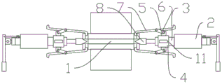
图3是本发明所述竖直管道截断装置的使用状态示意图。Fig. 3 is a schematic diagram of the use state of the vertical pipeline cutting device of the present invention.
图中,1、盲板;2、拉马本体;3、螺纹筒;4、调节环;5、连接部;6、连杆;7、拉钩;8、扩张楔;9、切割区;10、穿孔;11、旋拧块;12、连接螺纹杆。In the figure, 1. Blind plate; 2. Puller body; 3. Thread barrel; 4. Adjusting ring; 5. Connecting part; 6. Connecting rod; 7. Pull hook; Perforation; 11, screw block; 12, connecting threaded rod.
具体实施方式Detailed ways
下面将结合本发明实施例中的附图,对本发明实施例中的技术方案进行清楚、完整地描述,显然,所描述的实施例仅仅是本发明一部分实施例,而不是全部的实施例。基于本发明中的实施例,本领域普通技术人员在没有做出创造性劳动前提下所获得的所有其他实施例,都属于本发明保护的范围。The following will clearly and completely describe the technical solutions in the embodiments of the present invention with reference to the accompanying drawings in the embodiments of the present invention. Obviously, the described embodiments are only some, not all, embodiments of the present invention. Based on the embodiments of the present invention, all other embodiments obtained by persons of ordinary skill in the art without making creative efforts belong to the protection scope of the present invention.
在本发明的描述中,需要说明的是,术语“上/下端”、“内”、“外”“前端”、“后端”、“两端”、“一端”、“另一端”等指示的方位或位置关系为基于附图所示的方位或位置关系,仅是为了便于描述本发明和简化描述,而不是指示或暗示所指的装置或元件必须具有特定的方位、以特定的方位构造和操作,因此不能理解为对本发明的限制。此外,术语“第一”、“第二”仅用于描述目的,而不能理解为指示或暗示相对重要性。In the description of the present invention, it should be noted that the terms "upper/lower end", "inner", "outer", "front end", "rear end", "both ends", "one end", "another end" etc. indicate The orientation or positional relationship is based on the orientation or positional relationship shown in the drawings, and is only for the convenience of describing the present invention and simplifying the description, rather than indicating or implying that the referred device or element must have a specific orientation or be configured in a specific orientation. and operation, and therefore should not be construed as limiting the invention. In addition, the terms "first" and "second" are used for descriptive purposes only, and should not be understood as indicating or implying relative importance.
在本发明的描述中,需要说明的是,除非另有明确的规定和限定,术语“安装”、“设置/套设有”、“套接”、“连接”等,应做广义理解,例如“连接”,可以是固定连接,也可以是可拆卸连接,或一体地连接;可以是机械连接,也可以是电连接;可以是直接相连,也可以通过中间媒介间接相连,可以是两个元件内部的连通。对于本领域的普通技术人员而言,可以具体情况理解上述术语在本发明中的具体含义。In the description of the present invention, it should be noted that, unless otherwise clearly specified and limited, the terms "installation", "setting/setup", "socketing", "connection", etc. should be understood in a broad sense, for example "Connection" can be a fixed connection, a detachable connection, or an integral connection; it can be a mechanical connection or an electrical connection; it can be a direct connection or an indirect connection through an intermediary, and it can be two components Internal connectivity. Those of ordinary skill in the art can understand the specific meanings of the above terms in the present invention in specific situations.
本发明提供的一种竖直管道截断装置,包括两个扩张装置和一个盲板1,如图1所示,所述扩张装置包括拉马本体2、螺纹筒3、调节环4、连接部5、连杆6、拉钩7、扩张楔8,拉马本体2为液压拉马,螺纹筒3套在所述拉马本体2前端的伸缩轴上,并固定安装于拉马本体2上;调节环4咬合套装于螺纹筒3上,连接部5固定安装于调节环4两侧,连杆6可转动安装于调节环4上,拉钩7可转动铰接于连杆6外端;扩张楔8固定安装于拉马本体2伸缩端上;A vertical pipeline cutting device provided by the present invention includes two expansion devices and a
所述拉钩7的前端设有凸起,通过所述凸起与钩在连接法兰的螺栓孔内;The front end of the
所述调节环4为设有与螺纹筒3外壁的螺纹对应的内螺纹的管状结构,通过连接部5、连杆6和拉钩7可以使得拉钩7勾住的部位在上下方向扩张时仍然保持勾住状态,调节环4在螺纹筒3上转动可调节拉钩7的前后位置,使得拉钩7可以勾在连接法兰上。The
如图2所示,盲板1与竖直管道的连接法兰形状对应,所述盲板1上设有切割区9,切割区9为盲板1两侧的的平面结构,盲板1上设有穿孔10,穿孔10开于盲板1上且与竖直管道的连接法兰上的连接螺栓位置对应,切割区9使得位于两侧的连接螺栓落于盲板1外,通过切割区9在扩张楔8插入到连接法兰上的缝隙内时,扩张楔8不会对盲板1的插入造成干扰。As shown in Figure 2, the
如图3所示,调节环4上设有旋拧块11,旋拧块11固定安装于调节环4外表面上,通过旋拧块11便于旋拧调节环4增加旋拧时的力臂长度。As shown in Figure 3, the adjusting
所述扩张楔8上设有连接螺纹杆12,连接螺纹杆12咬合插装于扩张楔8上且咬合插装于拉马本体2的伸缩端上进而将扩张楔8与拉马本体2的伸缩端固定连接,通过连接螺纹杆12便于对扩张楔8进行拆装,在对不同的竖直管道和连接法兰扩张时,便于更换不同规格的扩张楔8。The
一种竖直管道截断方法,包括如下步骤:A method for cutting a vertical pipeline, comprising the steps of:
步骤一:将竖直管道最近的阀门关闭,对竖直管道进行初步阻断,防止在本装置工作时大量流体溢出;Step 1: Close the nearest valve of the vertical pipeline, and initially block the vertical pipeline to prevent a large amount of fluid from overflowing when the device is working;
步骤二:将竖直管道需要截断部位的连接法兰上的连接螺栓拆除,便于拉钩进行钩挂;Step 2: Remove the connecting bolts on the connecting flange where the vertical pipeline needs to be cut off, so that the hook can be hooked;
步骤三:将两个扩张装置上的拉钩分别勾在连接法兰两侧的上下的连接螺栓的穿孔上,对扩张装置上的拉马本体进行限位;Step 3: Hook the pull hooks on the two expansion devices on the perforations of the upper and lower connecting bolts on both sides of the connecting flange respectively, and limit the position of the puller body on the expansion device;
步骤四:操作拉马本体使得扩张楔前端对准竖直管道上的连接法兰的连接接缝处,驱动两个拉马本体进而使得拉马本体的伸缩端带动扩张楔伸出,扩张楔对连接法兰解封处进行扩张;Step 4: Operate the puller body so that the front end of the expansion wedge is aligned with the connection joint of the connecting flange on the vertical pipe, drive the two puller bodies so that the telescopic end of the puller body drives the expansion wedge out, and the expansion wedge Expansion at the unsealing part of the connecting flange;
步骤五:当连接法兰接缝处的缝隙宽度扩张至大于盲板的厚度时,将盲板插入到连接法兰的接缝处,插入时能将切割区朝向扩张楔侧,进而避免扩张楔对盲板的插入造成干扰;Step 5: When the width of the gap at the joint of the connecting flange expands to be greater than the thickness of the blind plate, insert the blind plate into the joint of the connecting flange. When inserting, the cutting area can be directed toward the side of the expansion wedge, thereby avoiding the expansion wedge Interference with the insertion of the blind plate;
步骤六:操作拉马本体取出两个扩张装置然后利用连接螺栓穿过连接法兰和盲板上的穿孔后拧紧,完成竖直管道截断。Step 6: Operate the main body of the puller to take out the two expansion devices, then use the connecting bolts to pass through the holes in the connecting flange and the blind plate, and then tighten them to complete the vertical pipe truncation.
需要说明的是,在本文中,诸如第一和第二等之类的关系术语仅仅用来将一个实体或者操作与另一个实体或操作区分开来,而不一定要求或者暗示这些实体或操作之间存在任何这种实际的关系或者顺序。而且,术语“包括”、“包含”或者其任何其他变体意在涵盖非排他性的包含,从而使得包括一系列要素的过程、方法、物品或者设备不仅包括那些要素,而且还包括没有明确列出的其他要素,或者是还包括为这种过程、方法、物品或者设备所固有的要素。在没有更多限制的情况下。由语句“包括一个......限定的要素,并不排除在包括所述要素的过程、方法、物品或者设备中还存在另外的相同要素”。It should be noted that in this article, relational terms such as first and second are only used to distinguish one entity or operation from another entity or operation, and do not necessarily require or imply that there is a relationship between these entities or operations. There is no such actual relationship or order between them. Furthermore, the term "comprises", "comprises" or any other variation thereof is intended to cover a non-exclusive inclusion such that a process, method, article, or apparatus comprising a set of elements includes not only those elements, but also includes elements not expressly listed. other elements of or also include elements inherent in such a process, method, article, or device. without further restrictions. The phrase "the inclusion of an element defined by ... does not preclude the presence of additional identical elements in the process, method, article, or apparatus comprising said element".
尽管已经示出和描述了本发明的实施例,对于本领域的普通技术人员而言,可以理解在不脱离本发明的原理和精神的情况下可以对这些实施例进行多种变化、修改、替换和变型,本发明的范围由所附权利要求及其等同物限定。Although the embodiments of the present invention have been shown and described, those skilled in the art can understand that various changes, modifications and substitutions can be made to these embodiments without departing from the principle and spirit of the present invention. and modifications, the scope of the invention is defined by the appended claims and their equivalents.
Claims (8)
Priority Applications (1)
| Application Number | Priority Date | Filing Date | Title |
|---|---|---|---|
| CN202211291468.1A CN115681663A (en) | 2022-10-19 | 2022-10-19 | A vertical pipeline cutting device and method |
Applications Claiming Priority (1)
| Application Number | Priority Date | Filing Date | Title |
|---|---|---|---|
| CN202211291468.1A CN115681663A (en) | 2022-10-19 | 2022-10-19 | A vertical pipeline cutting device and method |
Publications (1)
| Publication Number | Publication Date |
|---|---|
| CN115681663A true CN115681663A (en) | 2023-02-03 |
Family
ID=85066408
Family Applications (1)
| Application Number | Title | Priority Date | Filing Date |
|---|---|---|---|
| CN202211291468.1A Pending CN115681663A (en) | 2022-10-19 | 2022-10-19 | A vertical pipeline cutting device and method |
Country Status (1)
| Country | Link |
|---|---|
| CN (1) | CN115681663A (en) |
Citations (5)
| Publication number | Priority date | Publication date | Assignee | Title |
|---|---|---|---|---|
| US3997957A (en) * | 1974-08-14 | 1976-12-21 | Hokko Co., Ltd. | Device for replacing packings of flange joints |
| CN2626674Y (en) * | 2003-07-11 | 2004-07-21 | 刘达成 | Mechanical type flange separator |
| CN204505147U (en) * | 2015-02-28 | 2015-07-29 | 赵龙 | Multiplex hydraulic screw extractor instrument |
| CN209466176U (en) * | 2019-02-18 | 2019-10-08 | 中国化学工程第三建设有限公司 | Flange spreader |
| CN218719680U (en) * | 2022-10-19 | 2023-03-24 | 四川红华实业有限公司 | Vertical pipeline cuts device |
-
2022
- 2022-10-19 CN CN202211291468.1A patent/CN115681663A/en active Pending
Patent Citations (5)
| Publication number | Priority date | Publication date | Assignee | Title |
|---|---|---|---|---|
| US3997957A (en) * | 1974-08-14 | 1976-12-21 | Hokko Co., Ltd. | Device for replacing packings of flange joints |
| CN2626674Y (en) * | 2003-07-11 | 2004-07-21 | 刘达成 | Mechanical type flange separator |
| CN204505147U (en) * | 2015-02-28 | 2015-07-29 | 赵龙 | Multiplex hydraulic screw extractor instrument |
| CN209466176U (en) * | 2019-02-18 | 2019-10-08 | 中国化学工程第三建设有限公司 | Flange spreader |
| CN218719680U (en) * | 2022-10-19 | 2023-03-24 | 四川红华实业有限公司 | Vertical pipeline cuts device |
Similar Documents
| Publication | Publication Date | Title |
|---|---|---|
| CN208117746U (en) | A kind of oil and gas pipeline valve extracting tool | |
| CN112483753B (en) | An anti-clogging curved connecting pipe | |
| CN106854981A (en) | A kind of double dynamical snap joint auger stem | |
| CN218719680U (en) | Vertical pipeline cuts device | |
| CN115681663A (en) | A vertical pipeline cutting device and method | |
| CN211010394U (en) | Pipeline plugging device with pressure | |
| CN111520540A (en) | A kind of installation device and installation method for T-type joint ductile iron pipe | |
| CN213177283U (en) | Aerating device for municipal pipeline restoration | |
| CN204700843U (en) | a jacking tool | |
| CN117300652A (en) | Opening and closing mechanism for pipe cutting machine body | |
| CN219971728U (en) | Pipeline installation auxiliary assembly | |
| CN217843016U (en) | Pipeline quick-connecting piece | |
| CN213392021U (en) | Swing type drill rod connector for power faucet | |
| CN218719082U (en) | Quick-opening type pressure release valve | |
| CN206873533U (en) | Variable cross section mud delivery pipeline reducing device | |
| CN221880551U (en) | Communicating pipe for high-rise building | |
| CN217256002U (en) | Rubber tube disassembling tool | |
| CN218913899U (en) | Valve convenient to dismouting | |
| CN108127383B (en) | A method for replacing the oil inlet pipe of a crane | |
| CN219119206U (en) | An orifice sealing device and a shock wave generating system | |
| CN212203621U (en) | Hydraulic engineering is with type water conservancy pipeline that prevents frostbite | |
| CN219366914U (en) | Valve suitable for high-rise fire extinguishment | |
| CN222503054U (en) | A flange convenient for butt assembly | |
| CN218894630U (en) | Reinforcing auxiliary device is salvaged in workover | |
| CN222297286U (en) | A solenoid valve that is easy to connect |
Legal Events
| Date | Code | Title | Description |
|---|---|---|---|
| PB01 | Publication | ||
| PB01 | Publication | ||
| SE01 | Entry into force of request for substantive examination | ||
| SE01 | Entry into force of request for substantive examination |