CN115673391A - Edge milling device and edge milling assembly thereof - Google Patents
Edge milling device and edge milling assembly thereof Download PDFInfo
- Publication number
- CN115673391A CN115673391A CN202210883348.4A CN202210883348A CN115673391A CN 115673391 A CN115673391 A CN 115673391A CN 202210883348 A CN202210883348 A CN 202210883348A CN 115673391 A CN115673391 A CN 115673391A
- Authority
- CN
- China
- Prior art keywords
- milling
- edge
- edge milling
- milling cutter
- assembly
- Prior art date
- Legal status (The legal status is an assumption and is not a legal conclusion. Google has not performed a legal analysis and makes no representation as to the accuracy of the status listed.)
- Pending
Links
Images


Abstract
The invention provides an edge milling device and an edge milling assembly thereof, wherein the edge milling device comprises a base platform with a working surface and at least one edge milling assembly arranged on the working surface in a movable mode, so that the edge milling assembly can be used for processing the side surface of a target object, the production time course is accelerated, and the production efficiency is improved.
Description
Technical Field
The invention relates to a machine tool for processing burrs, in particular to an edge milling device and an edge milling assembly thereof.
Background
At present, the raised floor device is widely applied to an anti-static machine room or a dust-free room, wherein, the raised floor formed by die casting of the existing aluminum alloy is generally manufactured by five main processes of die sinking, aluminum melting, die casting, forming, trimming and the like. Because in the forming process, the surface and the bottom of the raised floor have a plurality of burrs, and these flaw burrs can not closely laminate between the raised floor on the one hand and also can not laminate between the platform frame in the installation process, and on the other hand is also not favorable to the installation of workers, and can have certain safety carelessness to the workers.
However, in the existing method, the burrs of the formed raised floor must be removed manually, which is not only inefficient in production efficiency, but also time-consuming and labor-consuming because a large amount of manpower is wasted in each processing.
Therefore, how to overcome the above drawbacks of the prior art has become a problem to be overcome in the industry.
Disclosure of Invention
In view of the above-mentioned drawbacks of the prior art, an object of the present invention is to provide an edge milling device and an edge milling assembly thereof, which can solve at least some of the problems of the prior art.
The edge milling assembly of the invention comprises: at least one milling cutter tool; a support structure, which is a plate base body, driving the milling cutter tool to linearly displace; the bearing structure is movably arranged on the supporting structure and bears the milling cutter tool so as to enable the bearing structure and the milling cutter tool to approach or be far away from a target object and enable the milling cutter tool to carry out edge milling treatment on the target object; and at least one servo motor which is combined with the milling cutter tool in a linear mode through a coupler and is configured on the bearing structure so as to directly drive the milling cutter tool through the coupler.
In the foregoing edge milling assembly, a displacement direction of the supporting structure is perpendicular to a displacement direction of the carrying structure.
In the foregoing edge milling assembly, the bearing structure is fixedly provided with a ball nut, and a motor drives a ball screw to rotate so as to drive the ball nut to perform a linear motion, so as to drive the bearing structure to linearly displace and displace the milling cutter tool to a desired position.
In the foregoing edge milling assembly, the servo motor is fixed to an upper seat of a shaft coupling seat by using a bolt, a lower seat of the shaft coupling seat is fixed to a milling cutter head of the milling cutter by using a bolt, and a shaft coupling for coupling the servo motor and the milling cutter head is provided in the shaft coupling seat, and the shaft coupling is made of a cylindrical structure made of a high vibration damping material, so that a rotating shaft of the servo motor is fixed to one end of the shaft coupling, and a rotating shaft of the milling cutter head is fixed to the other end of the shaft coupling. For example, the at least one servo motor is four servo motors, and the four servo motors simultaneously and respectively rotate four milling tools, so that the four milling tools can be simultaneously machined.
The invention further provides an edge milling device, which comprises: the aforementioned edge milling assembly; a base platform which is provided with a working surface, and the edge milling assembly is arranged on the working surface in a displaceable mode, wherein the supporting structure is arranged on the base platform in a movable mode; the positioning structure is arranged on the working surface to place the target, the edge milling assembly is arranged on the side edge of the positioning structure to move relative to the positioning structure to perform edge milling processing on the target, the target is provided with a first surface and a second surface which are opposite, a side surface adjacent to the first surface and the second surface and a flange protruding out of the side surface, and four corners of the second surface are provided with four footstands; and the fixing part is arranged corresponding to the positioning structure so as to press the target object on the positioning structure.
In the edge milling device, the fixing portion is disposed above the positioning structure and/or outside a pair of corners of the positioning structure. For example, the fixing portion is moved by a power source to be pressed or pulled downward, and presses the second surface of the object when the fixing portion is pressed downward, and separates the object when the fixing portion is pulled upward.
In the foregoing edge milling device, a double-rail structure is fixed on the base platform, and a sliding seat for being mounted on the double-rail structure is fixed at the bottom of the supporting structure, so that the sliding seat can slide on the double-rail structure to drive the supporting structure to linearly displace.
In the foregoing edge milling device, the support structure is fixedly provided with the ball nut and the ball screw engaged with the ball nut, and the first motor drives the ball screw to rotate so as to drive the ball nut to make linear motion, so that the support structure performs long-distance linear displacement along the edge of the positioning structure relative to the base platform, so that the milling cutter tool can linearly displace along the side surface of the target object to process the flange of the target object, and the four first motors simultaneously and respectively drive the four ball screws to rotate, so that the milling cutter tool can simultaneously process the four flanges of the target object.
In the foregoing edge milling device, a slide rail for guiding the support structure to move is disposed on the working surface of the base.
In the foregoing edge milling device, the base is provided with at least one power unit, and the power unit includes a first motor for driving the support structure to move and a second motor for driving the support structure to move.
In view of the above, the edge milling device and the edge milling assembly thereof of the present invention mainly drive the milling cutter tool through the servo motor, so that the edge milling assembly performs the side burr milling treatment on the target object, such as the raised floor, thereby accelerating the production time, improving the production efficiency, and reducing the manpower requirement.
Drawings
Fig. 1A is a front perspective view of an edge milling device applied to a processing apparatus.
FIG. 1A-1 is a rear perspective view of FIG. 1A.
Fig. 1B is a perspective view of a transport device of the processing tool of fig. 1A.
FIG. 1B-1 is a partially enlarged perspective view of FIG. 1B.
FIG. 1B-2 is a schematic front plan view of another embodiment of FIG. 1B.
FIG. 1B-3 is a top plan view of FIG. 1B-2.
Fig. 1C is a schematic top perspective view of an object to be processed by the processing apparatus of fig. 1A.
FIG. 1C-1 is a bottom perspective view of FIG. 1C.
FIG. 1C-2 is a schematic side plan view of FIG. 1C.
FIG. 1D is a schematic side plan view of the completed target object processed by the processing apparatus of FIG. 1A.
Fig. 2A is a perspective view of the edge milling device of the present invention.
Fig. 2A-1 is a partially exploded perspective view of fig. 2A.
Fig. 2A-2 is a partially exploded perspective view of fig. 2A.
Fig. 2B is a top plan view of fig. 2A.
Fig. 2C is a side plan view of fig. 2A.
Fig. 2D is a partially enlarged perspective view of fig. 2A.
Fig. 2E is a partial plan perspective view of fig. 2A.
The reference numbers are as follows:
1. processing equipment
1a transport device
10. Pick-and-place assembly
10a gripping part
10b bearing part
10c power part
10d power source
10e servo motor
100. Clamping piece
101. Telescopic structure
102. Cylinder
11,11a support assembly
110. Rod rack
111. Cross beam
112. Sliding rail
112a rack
113. Gear wheel
114. Speed reducer
115,361 bolt
116. Sliding seat
2. Milling height device
3. Edge milling device
3a edge milling assembly
3b fixing component
30. Milling cutter tool
30a body
300. Milling cutter
31. Base station
32. Positioning structure
32a placing platform
320. Fixing part
320a fixed part
33. Support structure
330. Sliding seat
34. Bearing structure
34a support
340. Sliding block
35. Track
36. Servo motor
36a coupling seat
36b milling head
36c,362 axle
360. Coupling device
363. Upper seat body
364. Lower seat body
37. Sliding rail
38. Power set
38a first motor
38b second motor
380. Ball screw
39. Supporting frame
390. Main frame
391. Arm support
392. Support frame
4. Turning device
5. Pore-forming device
8,9 target
9a first surface
9b second surface
9c side surface
9d end face
90. Foot seat
91. Flange
900. Opening holes
Width D
f1, f2, b1, b2 moving direction
h height difference
S working surface
Directions of arrows X, Y, Z
Detailed Description
The embodiments of the present invention are described below with reference to specific embodiments, and other advantages and effects of the present invention will be easily understood by those skilled in the art from the disclosure of the present specification.
It should be understood that the structures, proportions, and dimensions shown in the drawings and attached to the specification are only for the purpose of understanding and reading the present disclosure, and are not intended to limit the scope of the present disclosure, which is in any way obvious to those skilled in the art. In addition, the terms "upper", "lower", "front", "rear", "left", "right" and "one" used in the present specification are used for clarity of description, and are not intended to limit the scope of the present invention, and the relative relationship between the terms and the terms may be changed or adjusted without substantial technical change.
Fig. 1A and 1A-1 are perspective views of a processing apparatus 1 according to the present invention. As shown in fig. 1A and 1A-1, the processing apparatus 1 includes: a transporting device 1a, a milling height device 2, an edge milling device 3, a turning device 4 and a hole forming device 5.
In the present embodiment, the processing apparatus 1 defines the direction of the production line as the left and right directions (as indicated by the arrow Y), the direction perpendicular to the production line as the front and rear directions (as indicated by the arrow X), and the height direction along the processing apparatus 1 as the up and down directions (as indicated by the arrow Z). It should be understood that this orientation is used to illustrate the configuration of the present embodiment, and is not particularly limited.
The transportation device 1a is used for transporting (e.g. clamping) the object 9 to a desired processing position of the production line, so that the transportation device 1a is disposed at the upper periphery of the milling height device 2, the edge milling device 3, the turning device 4 and the hole forming device 5 for placing the object 9, thereby facilitating the object 9 to be placed on the milling height device 2, the edge milling device 3, the turning device 4 and/or the hole forming device 5.
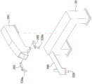
In the present embodiment, as shown in fig. 1B, the transportation device 1a includes at least one pick-and-place assembly 10 and a supporting assembly 11 movably erecting the pick-and-place assembly 10 (the supporting assembly 11 includes two rod frames 110 and a beam 111 disposed on the two rod frames 110), so that the pick-and-place assembly 10 is used for picking and placing the target 9, and the pick-and-place assembly 10 moves to move the target 9 in coordination with the supporting assembly 11.
Furthermore, the pick-and-place assembly 10 includes a clamping portion 10a having the clamping member 100 and a supporting portion 10b for supporting the clamping portion 10a.
In an embodiment, as shown in fig. 1B-1 (or the supporting component 11a shown in fig. 1B-2 and fig. 1B-3), a sliding rail 112 and a sliding seat 116 for guiding the displacement of the pick-and-place component 10 may be disposed on the cross beam 111, wherein the sliding rail 112 is fixed on the cross beam 111, the sliding seat 116 is fixed on the carrying portion 10B, the sliding seat 116 and the carrying portion 10B linearly move on the sliding rail 112, and at least one rack 112a and a gear 113 engaging with the rack 112a and axially connected to the pick-and-place component 10 are disposed, the rack 112a is fixed on the cross beam 111, a servo motor 10e and a reducer 114 are fixed on the carrying portion 10B, so that the gear 113 is rotated by the servo motor 10e or the power portion 10c to roll along the rack 112a to linearly displace the pick-and-place component 10, so that the pick-and-place component 10 can be stably linearly displaced between the two bar frames 110 through the sliding rail 112. Specifically, the servo motor 10e rotates the gear 113 in cooperation with a reducer 114 fixed (e.g., a bolt 115 shown in fig. 1B-1) to the bearing portion 10B. It should be understood that the support members 11,11a are not particularly limited, and may be of various types.
For example, the width D of the clamping unit 100 of the clamping unit 10a can be adjusted as required to clamp the target objects 9 with different widths, an oil cylinder or a pneumatic cylinder (which is used as a power source 10D) can be used to control the distance between the two clamping units 10a to clamp or loosen the target object 9, the carrying unit 10B is a moving frame which is vertically arranged on the beam 111 (or the slide rail 112) and pivotally connected to the gear 113, the gear 113 is engaged with the rack 112a (as shown in fig. 1B-1), the gear 113 is driven by an external force (such as a servo motor 10 e) in cooperation with the reducer 114, so that the pick-and-place unit 10 can move back and forth on a slide (such as the carrying unit 10B) and a slide rail assembly (such as the slide rail 112 and the rack 112a and the gear 113 thereon) in a linear direction Y along an arrow direction. Specifically, the clamping unit 10a drives the clamping members 100 to extend or retract (in the direction of arrow Y) through a plurality of power sources 10d (such as pneumatic or hydraulic cylinders shown in fig. 1B) to generate an opening or clamping action, and an extension structure 101 (such as a guide rod shown in fig. 1B-1) connected to the clamping unit 10a is disposed at the bottom of the carrying unit 10B to lift the clamping unit 10a through a cylinder 102.
In addition, the number of the pick-and-place assemblies 10 can be set according to the requirement. For example, the pick-and-place assemblies 10 are respectively disposed at the processing positions corresponding to the milling height device 2, the edge milling device 3 and the turnover device 4, so at least two sets of pick-and-place assemblies 10 are provided. Specifically, each pick-and-place assembly 10 is respectively disposed between the milling height device 2 and the edge milling device 3 and between the edge milling device 3 and the turnover device 4, and the pick-and-place assemblies 10 can be additionally disposed between the rod frame 110 and the milling height device 2 as required (as indicated by the dotted line in fig. 1B-2), so that a plurality of pick-and-place assemblies 10 are used as intermediate transfer assemblies for the target 9, and the target 9 is continuously picked and placed to each processing position, thereby completing the processing flow of the whole production line.
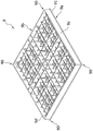
In addition, the target 9 is a raised floor, as shown in FIG. 1C, FIG. 1C-1, and FIG. 1C-2, having opposing first and second surfaces 9a (e.g., floor surfaces) and 9b (e.g., bottom ends) and a side surface 9C adjacent to the first and second surfaces 9a, 9b. For example, the target 9 is substantially rectangular (e.g. square), the bottom of the target 9 (e.g. the side of the second surface 9b, which is the bottom of the raised floor) is honeycomb-shaped, and the four corners of the second surface 9b of the target 9 are formed with the foot seats 90, so that the four foot seats 90 are provided with openings 900 (as shown in fig. 1D), and the four foot seats 90 are fixed on the supporting feet of the raised floor respectively by using screws. Specifically, the end surface 9d of the foot 90 slightly protrudes (as the height difference h shown in fig. 1C-2) out of the second surface 9b of the target 9, and a flange 91 protruding out of the side surface 9C is formed at the edge of the first surface 9a, where the flange 91 is the four edges of the edge milling device 3 that need to process the raised floor. Since the object 9 of the present embodiment is a raised floor, the object 9 will be referred to as a raised floor hereinafter.
Fig. 2A to 2E are schematic views of the edge milling device 3 of the present invention. In the present embodiment, the edge milling unit 3a of the edge milling device 3 is operated in cooperation with the transportation device 1a for processing the flange 91 on the side surface 9C of the target 8,9 (raised floor) as shown in fig. 1C to 1D, and the flange 91 is used for the edge milling device 3 to rapidly complete the processing of four edges of the raised floor, for example, to remove burrs from the peripheral sides of the raised floor, so as to process the four edge dimensions of the raised floor. Specifically, a processing numerical value is input in a Programmable Logic Controller (PLC) mode through a human-machine control interface to control the dimensions of the four edges of the raised floor to be processed.
As shown in fig. 2A to 2E, the edge milling assembly 3a for processing four edge flanges 91 of the target object 9 comprises at least one servo motor 36 and the milling tool 30, a supporting structure 33 and a carrying structure 34 disposed on the supporting structure 33 for carrying a plurality of milling tools 30, wherein the milling tool 30 is provided with a milling tool 300 at the top end of the body 30a thereof, and the carrying structure 34 is movably disposed on the supporting structure 33. The target 9 is fixed on the fixing component 3b, the fixing component 3b includes a base 31 and a positioning structure 32 disposed on the base 31, so that at least one edge milling component 3a can be disposed on the base 31 and around the positioning structure 32, so that the transporting device 1a can place the target 9 on the positioning structure 32, and the edge milling component 3a can move relative to the positioning structure 32 to perform edge milling processing on the target 9.
The base 31 is a machine tool table, and is substantially rectangular, and the working surface S thereof is also a rectangular plane.
In the present embodiment, the base station 31 can be configured with electromechanical components required by the production line, such as a motor, a wire, or other related units, without any particular limitation.
The positioning structure 32 is disposed in the middle of the working surface S of the base 31, as shown in fig. 2A-1, to position and carry the target 9 shown in fig. 1C.
In this embodiment, the positioning structure 32 is a multi-layer rectangular plate block, a square placing platform 32a is disposed above the positioning structure, and the raised floor is placed on the placing platform 32a, so that the edge milling assemblies 3a are respectively disposed on four sides of the placing platform 32a (in this embodiment, four edge milling assemblies 3a are shown in total).
Furthermore, the fixing component 3b further includes at least one fixing portion 320,320a, and the fixing portion 320,320a is disposed outside the placing platform 32a to limit the displacement of the target 9 and avoid the deviation. For example, a gantry-shaped supporting frame 39 is respectively disposed on the front and back sides of the base 31, as shown in fig. 2A-2, the fixing portions 320 are erected on the main frame 390 extending from the surface of the supporting frame 39, so that when the target 9 is placed on the placing platform 32A, the feet 90 of the target 9 are pressed and clamped diagonally by the fixing portions 320, so as to prevent the target 9 from being deviated during the edge milling process.
In addition, the fixing portion 320a can also be disposed above the placing platform 32a to limit the displacement and deviation of the target 9. For example, the supporting frame 39 is provided with a frame 391, as shown in fig. 2A-2, which is pivotally connected to a support 392 to erect the fixing portion 320a through the support 392, so that after the target 9 is placed on the placing platform 32A, the support 392 is rotated to press the fixing portions 320a to fasten the second surface 9b of the target 9, so as to prevent the target 9 from being deviated during the edge milling process.
The edge milling device 3 is provided with at least one edge milling assembly 3a, which is respectively disposed outside each side (such as front, rear, left and right sides) of the positioning structure 32 (or the placing platform 32 a).
In the present embodiment, each of the edge milling assemblies 3a includes the milling cutter 30, a supporting structure 33 disposed on the base 31, and a carrying structure 34 disposed on the supporting structure 33 for carrying a plurality of milling cutters 30, and the milling cutter 30 is configured with a milling cutter 300 at a top end of a body 30a of the milling cutter 30, and the carrying structure 34 is movably disposed on the supporting structure 33 for moving the milling cutter 30 to a desired position. It should be understood that the milling cutter 300 is not particularly limited with respect to its wide variety.
Furthermore, the supporting structure 33 is a board base body, which is disposed on the working surface S of the base 31 in a displaceable manner. For example, a slide rail 37 for limiting the displacement direction of the supporting structure 33 and a power set 38 for driving the supporting structure 33 and the carrying structure 34 to displace are disposed on the working surface S of the base 31. Specifically, the slide rail 37 is a double-rail structure fixed on the base 31, and the bottom of the supporting structure 33 is fixed with a slide seat 330 for being mounted on the slide rail 37, so that the slide seat 330 can slide on the slide rail 37 to drive the supporting structure 33 to move linearly. A ball nut (not shown) and a ball screw 380 (fixed on the working surface S of the base 31) engaged with the ball nut are fixed at the bottom of the supporting structure 33, the power unit 38 includes a first motor 38a, so that the ball screw 380 is driven by the first motor 38a to rotate and drive the ball nut to move linearly, so that the supporting structure 33 linearly moves along the edge of the positioning structure 32 along a long distance relative to the base 31, and the milling cutter 30 can linearly move along the side surface 9c of the target 9 to process the flange 91 of the target 9, and the four first motors 38a simultaneously drive the ball screw 380 to rotate, so that the milling cutter 30 can simultaneously process the flange 91 of the target 9, thereby saving the processing time.
In addition, the supporting structure 34 is a frame seat and is movably disposed on the supporting structure 33, so that the milling cutter 30 approaches or departs from the positioning structure 32, and the power set 38 further includes a second motor 38B for driving the supporting structure 34 to displace, wherein, based on one side of the positioning structure 32, a displacement direction (a displacement direction f2, B2 shown in fig. 2B) of the supporting structure 33 is perpendicular to a displacement direction (a displacement direction f1, B1 shown in fig. 2B) of the supporting structure 34. For example, a rail 35 is disposed on the upper side of the supporting structure 33, so that the sliding block 340 below the bearing structure 34 is engaged with the rail 35, the sliding block 340 moves on the rail 35, and the second motor 38b drives the bearing structure 34 to linearly displace along the rail 35 along a short distance relative to the supporting structure 33, so that the milling cutter tool 30 can be linearly displaced to a desired plane position or machining position to approach or move away from the positioning structure 32. Specifically, a ball nut (not shown) is fixed on the lower side of the bearing structure 34, and a ball screw (not shown) engaged with the ball nut is fixed on the supporting structure 33, so that the second motor 38b rotates the ball screw, and the ball screw drives the ball nut to generate linear displacement because the ball screw rotates only in situ and does not move, so that the ball nut linearly drives the bearing structure 34 to displace along the rail 35, and the milling cutter tool 30 is linearly displaced to a desired processing position.
In addition, a servo motor 36 and the milling cutter tool 30 are disposed on the supporting structure 34 by a bracket 34a, the servo motor 36 and the milling cutter tool 30 are linearly combined into a whole, so that the volume of the supporting structure 34 can be reduced, the milling cutter tool 30 is directly driven to rotate by the servo motor 36, and the burr of the flange 91 of the target object 9 is removed from the milling cutter 300 at a target position (such as the flange 91 attached to the side surface 9c of the target object 9). Specifically, the bearing structure 34 is configured with the milling cutter tool 30 and a servo motor 36 for actuating the milling cutter tool 30 to rotate, and as shown in fig. 2D and fig. 2E, the servo motor 36 is fixed on the upper seat 363 of the coupling seat 36a by bolts 361, and the lower seat 364 of the coupling seat 36a is fixed on the milling cutter head 36b of the milling cutter tool 30 by bolts 361, so as to actuate the milling cutter tool 30 to rotate, so that the milling cutter tool 30 removes burrs of the flange 91 of the object 9 at a target position (such as the flange 91 attached to the side surface 9c of the object 9), wherein, a coupling 360 for coupling the servo motor 36 and the milling cutter head 36b is provided in the coupling seat 36a, which is made of a cylindrical structure made of high damping material, so that the rotating shaft 36c of the servo motor 36 is fixed at one end of the coupling 360, and the rotating shaft 362 of the milling cutter head 36b is fixed at the other end of the coupling 360, and four servo motors 36 rotate simultaneously, so that the milling cutter tool 30 can simultaneously process the flange 91 of the object 9, thereby saving three times for processing time.
Therefore, the main feature of the present invention is that the servo motor 36 is used to directly drive the milling cutter tool 30 to rotate, which not only reduces the volume of the edge milling device 3, but also improves the machining precision and speed by digitally controlling the rotation of the servo motor 36, which is an efficiency that cannot be achieved by the conventional motor drive.
When the edge milling device 3 is used in a production line, after the milling operation is completed, a single target 9 is transported from the milling device 2 to the placing platform 32a of the positioning structure 32 of the edge milling device 3 by the transporting device 1a, and the target 9 is firmly supported by a plurality of fixing parts 320,320a, wherein the first surface 9a of the target 9 faces the placing platform 32a, and the second surface 9b faces upwards.
Then, the supporting structure 34 is moved close to the positioning structure 32 (or the placing platform 32 a) by the second motor 38B (as shown in the moving direction f1 of fig. 2B) to move the edge milling assembly 3a to a desired position, and the supporting structure 33 is linearly slid along the slide rail 37 by the first motor 38a (as shown in the moving direction f2 of fig. 2B) to move the milling tool 30, so that the servo motor 36 drives the milling tool 300 of the milling tool 30 to mill burrs of the flange 91 of the four side surfaces 9c of the target 9, so that the edge milling assembly 3a performs an edge milling process on the target 9 corresponding to each edge of the positioning structure 32 (or the placing platform 32 a).
Thereafter, the supporting structure 34 is moved away from the positioning structure 32 (or the placing platform 32 a) (in the moving direction B1 shown in fig. 2B) by the second motor 38B to move the milling tool 30 to a desired position, and the supporting structure 33 is linearly slid along the slide rail 37 (in the moving direction B2 shown in fig. 2B) by the first motor 38a to move the edge milling assembly 3a back to the original point.
In summary, the edge milling device 3 of the present invention drives the milling cutter 30 by the servo motor 36, so that the edge milling assembly 3a processes burrs of the flange 91 on the side surface 9c of the raised floor, thereby increasing the production time, improving the production efficiency, and reducing the manpower requirement.
Furthermore, by designing the cyclic displacement (moving directions f1, f2, B1, B2 as shown in fig. 2B) of the edge milling unit 3a, the milling cutter 300 of the milling cutter tool 30 is prevented from repeatedly milling the flange 91 on the same side surface 9c, and thus the flange 91 on the side surface 9c of the target object 9 can be prevented from being excessively milled and damaged or the milling cutter 300 can be prevented from generating mechanical noise.
Furthermore, the servo motor 36 is driven by the coupling 360 to effectively absorb shock, so that the noise of the edge milling device 3 can be reduced during operation. For example, compared to the conventional belt-driven motor, the servo motor 36 is linearly combined with the milling cutter tool 30 through the coupling 360, which not only reduces the need of two pulleys and belts in the conventional transmission mechanism (i.e. the conventional motor needs to use the pulleys to drive the milling cutter tool to rotate), but also significantly reduces the size, greatly improves the precision, and further reduces the problems of vibration and noise generated by the pulley driving.
Therefore, the efficacy enhancement of the present invention is as follows:
first, the advantage of using the servomotor 36:
1. the response speed is fast, and the servo motor 36 can reach the required speed (above 2000 RPM) in a short time, so as to reduce the waiting time and improve the floor processing speed.
2. The servo motor 36 has a wide range of available rotation speed (3000-5000 RPM), the required rotation speed is adjusted according to different floor processing thicknesses, the service life of the cutter is prolonged, and the processing precision is improved. For example, when the thickness processing range of the raised floor is increased from 1mm to 2 to 12mm, the cutting speed is decreased by adjusting the rotation speed of the servo motor 36 because the cutting thickness is increased, the cutting resistance is also increased, and the cutting heat is increased.
3. The servo motor 36 can maintain stable torque at different rotation speeds, and directly drive the milling cutter tool 30 for machining, so that the problem that the traditional stepping motor cannot drive the milling cutter tool due to insufficient torque caused by high load, overlarge inertia or increased rotation speed is solved. It should be noted that the torque (torsion) of the conventional stepping motor decreases with the increase of the rotation speed.
Second, the advantage of the linear combination of the servomotor 36 of the present invention and the milling cutter tool 30 in an integral direct drive:
1. the occupied space is saved, and the size of the whole edge milling device 3 is smaller.
2. The efficiency can be improved and the power is not consumed in the speed reducing mechanism. For example, belts, chains, or components in the transmission used by conventional motors may rub against each other.
3. The noise can be reduced. The present invention has simple overall configuration and few parts, and the cylindrical coupling 360 is made of high vibration damping material, so that it is not easy to generate vibration and generates less noise.
4. The life can be extended and fewer components represent fewer parts that are susceptible to damage. For example, damage to conventional processing systems is likely to result from aging (e.g., belt stretching) or stress of the parts.
The foregoing embodiments are merely illustrative of the principles and utilities of the present invention and are not intended to limit the invention. Those skilled in the art can modify the above-described embodiments without departing from the spirit and scope of the present invention. Therefore, the scope of the invention should be determined from the following claims.
Claims (12)
1. An edge milling assembly comprising:
at least one milling cutter tool;
a support structure, which is a plate base body, driving the milling cutter tool to linearly displace;
the bearing structure is movably arranged on the supporting structure and bears the milling cutter tool so as to enable the bearing structure and the milling cutter tool to approach or be far away from a target object and enable the milling cutter tool to carry out edge milling treatment on the target object; and
at least one servo motor, which is combined with the milling cutter tool in a straight line mode through a coupler into a whole, is configured on the bearing structure, and directly drives the milling cutter tool through the coupler.
2. The edge milling assembly of claim 1, wherein the direction of displacement of the support structure is orthogonal to the direction of displacement of the load bearing structure.
3. The edge milling assembly of claim 1, wherein the support structure is secured with a ball nut, and a motor drives a ball screw to rotate and move the ball nut linearly, so as to linearly displace the support structure and thus displace the milling cutter tool to a desired position.
4. The edge milling assembly as claimed in claim 1, wherein the servo motor is fixed to an upper housing of a coupling base by bolts, and a lower housing of the coupling base is fixed to a milling head of the milling cutter tool by bolts, and a coupling for coupling the servo motor and the milling head is provided in the coupling base, and is formed in a cylindrical shape of high vibration damping material so that a rotation shaft of the servo motor is fixed to one end of the coupling and a rotation shaft of the milling head is fixed to the other end of the coupling.
5. The edge milling assembly of claim 4, wherein the at least one servo motor is four servo motors, and the four servo motors simultaneously rotate four milling tools respectively, so that the four milling tools can be simultaneously machined.
6. An edge milling apparatus comprising:
the edge milling assembly of any one of claims 1 to 5;
a base platform which is provided with a working surface, and the edge milling assembly is arranged on the working surface in a displaceable mode, wherein the supporting structure is arranged on the base platform in a movable mode;
the positioning structure is arranged on the working surface to place the target, the edge milling assembly is arranged on the side edge of the positioning structure to move relative to the positioning structure to perform edge milling processing on the target, the target is provided with a first surface and a second surface which are opposite, a side surface adjacent to the first surface and the second surface and a flange protruding out of the side surface, and four corners of the second surface are provided with four footstands; and
and the fixing part is arranged corresponding to the positioning structure so as to press the target object on the positioning structure.
7. The edge milling apparatus according to claim 6, wherein the fixing portion is disposed above the positioning structure and/or outside a pair of corners thereof.
8. The edge milling apparatus of claim 7, wherein the fixing portion is moved by a power source to be pressed or pulled downward, the fixing portion being pressed against the second surface of the object when pressed downward and separated from the object when pulled upward.
9. The edge milling apparatus according to claim 6, wherein a double-rail structure is fixed on the base platform, and a sliding seat for mounting to the double-rail structure is fixed at the bottom of the supporting structure, such that the sliding seat can slide on the double-rail structure to drive the supporting structure to linearly displace.
10. The edge milling device according to claim 6, wherein a ball nut and a ball screw engaged with the ball nut are fixed on the supporting structure, and the ball screw is driven by a first motor to rotate so as to drive the ball nut to move linearly, so that the supporting structure can move linearly along the edge of the positioning structure with respect to the base platform a long distance, so that the milling tool can move linearly along the side of the target object to machine the flange of the target object, and four first motors simultaneously drive four ball screws to rotate, respectively, so that the milling tool can machine four flanges of the target object at the same time.
11. An edge milling apparatus according to claim 6, wherein the working surface of the base is provided with a rail for guiding the support structure.
12. The edge milling apparatus of claim 6, wherein the base has at least one power pack disposed thereon, and the power pack comprises a first motor for driving the support structure to move and a second motor for driving the support structure to move.
Applications Claiming Priority (2)
| Application Number | Priority Date | Filing Date | Title |
|---|---|---|---|
| CN202110852675 | 2021-07-27 | ||
| CN2021108526759 | 2021-07-27 |
Publications (1)
| Publication Number | Publication Date |
|---|---|
| CN115673391A true CN115673391A (en) | 2023-02-03 |
Family
ID=85061390
Family Applications (1)
| Application Number | Title | Priority Date | Filing Date |
|---|---|---|---|
| CN202210883348.4A Pending CN115673391A (en) | 2021-07-27 | 2022-07-26 | Edge milling device and edge milling assembly thereof |
Country Status (1)
| Country | Link |
|---|---|
| CN (1) | CN115673391A (en) |
-
2022
- 2022-07-26 CN CN202210883348.4A patent/CN115673391A/en active Pending
Similar Documents
| Publication | Publication Date | Title |
|---|---|---|
| CN111215676A (en) | Milling height device | |
| CN115673879A (en) | Processing equipment | |
| CN218745071U (en) | Edge milling device and edge milling assembly thereof | |
| CN115673391A (en) | Edge milling device and edge milling assembly thereof | |
| CN219358033U (en) | Milling device and milling assembly thereof | |
| TWM596675U (en) | Milling height device | |
| CN217728096U (en) | Processing equipment | |
| KR20230017111A (en) | Edge milling device and edge milling component thereof | |
| CN115673389A (en) | Height milling device and height milling assembly thereof | |
| CN213504519U (en) | Tray replacing mechanism | |
| TWM629864U (en) | Processing equipment | |
| CN217727200U (en) | Pore-forming device and unit thereof | |
| CN212144655U (en) | Edge milling device | |
| TWI804392B (en) | Milling edge device and milling edge component thereof | |
| JP2023018623A (en) | Processing machine | |
| US20230226622A1 (en) | Machining apparatus | |
| TWM624285U (en) | Milling height device and milling height component thereof | |
| TWI804393B (en) | Milling height device and milling height component thereof | |
| US20230226623A1 (en) | Edge milling device and edge milling component thereof | |
| CN219853131U (en) | Processing Equipment | |
| CN115673371A (en) | Pore-forming device and unit thereof | |
| TW202132041A (en) | Milling edge device | |
| TW202404721A (en) | Milling height device and milling height component thereof | |
| TW201701988A (en) | Dual-head multipurpose machine tool having stable structure and enhancing machine precision, prolonging service life of the machine, and effectively enhancing machining efficiency | |
| CN218225471U (en) | Pore-forming device |
Legal Events
| Date | Code | Title | Description |
|---|---|---|---|
| PB01 | Publication | ||
| PB01 | Publication | ||
| SE01 | Entry into force of request for substantive examination | ||
| SE01 | Entry into force of request for substantive examination |