CN115664117A - Liquid cooling device of double-stator permanent magnet direct drive motor - Google Patents
Liquid cooling device of double-stator permanent magnet direct drive motor Download PDFInfo
- Publication number
- CN115664117A CN115664117A CN202211671858.1A CN202211671858A CN115664117A CN 115664117 A CN115664117 A CN 115664117A CN 202211671858 A CN202211671858 A CN 202211671858A CN 115664117 A CN115664117 A CN 115664117A
- Authority
- CN
- China
- Prior art keywords
- oil
- stator
- double
- stator shaft
- heat
- Prior art date
- Legal status (The legal status is an assumption and is not a legal conclusion. Google has not performed a legal analysis and makes no representation as to the accuracy of the status listed.)
- Granted
Links
Images


Classifications
-
- Y—GENERAL TAGGING OF NEW TECHNOLOGICAL DEVELOPMENTS; GENERAL TAGGING OF CROSS-SECTIONAL TECHNOLOGIES SPANNING OVER SEVERAL SECTIONS OF THE IPC; TECHNICAL SUBJECTS COVERED BY FORMER USPC CROSS-REFERENCE ART COLLECTIONS [XRACs] AND DIGESTS
- Y02—TECHNOLOGIES OR APPLICATIONS FOR MITIGATION OR ADAPTATION AGAINST CLIMATE CHANGE
- Y02T—CLIMATE CHANGE MITIGATION TECHNOLOGIES RELATED TO TRANSPORTATION
- Y02T10/00—Road transport of goods or passengers
- Y02T10/60—Other road transportation technologies with climate change mitigation effect
- Y02T10/64—Electric machine technologies in electromobility
Landscapes
- Motor Or Generator Cooling System (AREA)
Abstract
The invention discloses a liquid cooling device of a double-stator permanent magnet direct drive motor, which comprises an oil pan, cooling oil, a motor shell and an end cover, wherein a double-stator driving mechanism is arranged in the motor shell, and a passive oil cooling mechanism is arranged on the double-stator driving mechanism; the cold mechanism of passive oil is including advancing oil pipe, fuel feeding portion, exchange portion and receiving oil portion, and exchange portion includes heat-conducting plate and circulation subassembly, the heat-conducting plate both ends and rotor portion fixed connection, the distance of heat-conducting plate one end and stator axle is greater than the distance of the other end and stator axle, and the circulation subassembly is located heat-conducting plate one side and parallel with the heat-conducting plate. The invention has the advantages that the centripetal force generated by the rotation of the rotor can be utilized for the automatic circulation of the cooling liquid through the arrangement that the distance between one end of the heat-conducting plate and the stator shaft is larger than that between the other end of the heat-conducting plate and the stator shaft, and the circulation component is positioned at one side of the heat-conducting plate and is parallel to the heat-conducting plate; the centripetal forces with different forces are generated at different rotating speeds, so that the flow speed of the cooling oil is changed, and the purpose of adjusting the flow of the cooling oil according to the rotating speeds is achieved.
Description
Technical Field
The invention relates to the technical field of motor cooling, in particular to a liquid cooling device of a double-stator permanent magnet direct drive motor.
Background
With the development of science and technology, high-power motor units are applied more and more in various fields, particularly in the new energy automobile industry, the size and the weight of a general motor with high power are correspondingly increased, however, in some fields, the size and the weight are strictly required, and the power density of a traditional motor cannot meet the requirements; the double-stator motor can greatly improve the power of the motor under the condition of small volume increase;
although a conventional double-stator motor is known as a double-stator motor, for example, from patent No. CN201520946023.1, the cited patent adopts a double-stator driving method, but the width of the stator winding is the same, so that the structure is not compact enough, the power density is influenced to a certain extent, and if the structure can be optimized, the power density can be further improved.
The existing motor cooling device mostly dissipates heat of a shell of the motor, for example, patent number CN201210545703.3 named as a water-cooled motor, which can cool the motor, but has the following defects; 1. the water paths are distributed at the edge of the motor, so that the position of the center of the motor cannot be rapidly and effectively radiated, the temperature of the center of the motor is higher, and the service life of the winding of the stator on the inner side is influenced.
For example, patent No. CN201510161589.8 is a patent of a liquid-cooled motor cooler, which needs a water pump to actively drive water into a motor for cooling, so that additional energy consumption is increased, and the injection amount is not easy to adjust, and water cooling cannot be performed according to the actual rotating speed of the motor.
Disclosure of Invention
Aiming at the defects, the invention provides a liquid cooling device of a double-stator permanent magnet direct drive motor, which solves the problems.
In order to achieve the purpose, the invention adopts the following technical scheme:
a double-stator permanent magnet direct-drive motor liquid cooling device comprises an oil pan, cooling oil, a motor shell and end covers, wherein the end covers are located on two sides of the motor shell, the cooling oil is located in the oil pan, the motor shell is installed on the oil pan, a double-stator driving mechanism is arranged in the motor shell, and a driven oil cooling mechanism is installed on the double-stator driving mechanism;
the double-stator driving mechanism comprises a stator shaft, an iron core part and a rotor part, wherein the iron core part is provided with two groups, one group is positioned at the outer side of the rotor part and is fixedly connected with a motor shell, the other group is positioned at the inner side of the rotor part and is fixedly connected with the stator shaft, and the stator shaft is fixedly connected with an end cover; the rotor part is rotationally connected with the stator shaft;
the passive oil cooling mechanism comprises an oil inlet pipe, an oil supply part, an exchange part and an oil receiving part, wherein the oil supply part is arranged at one end of the stator shaft, the oil receiving part is arranged at the other end of the stator shaft, the exchange part is arranged on the rotor part, and the cooling oil flows back into the oil pan through the oil supply part, the exchange part and the oil receiving part;
the oil supply part radially divides the cooling oil into the exchange part, one end of the oil supply part is fixedly connected with the stator shaft, and the other end of the oil supply part is fixedly connected with the exchange part;
the exchange part comprises a heat-conducting plate and a circulation component, two ends of the heat-conducting plate are fixedly connected with the rotor part, the distance between one end of the heat-conducting plate and the stator shaft is larger than that between the other end of the heat-conducting plate and the stator shaft, and the circulation component is positioned on one side of the heat-conducting plate and is parallel to the heat-conducting plate; the circulating assembly is used for cooling oil circulation;
the oil collecting part comprises a return pipe and a sealed cavity, and the cooling oil is discharged from the exchange part, enters the sealed cavity and returns to the oil pan through the return pipe.
Further, the iron core part comprises a first winding coil arranged on an inner ring of the motor shell; the motor comprises an end cover and is characterized in that a circular hole is formed in the side surface of the end cover, a stator shaft penetrates through the circular hole and extends into a motor shell, a fastening bolt is installed at one end of the stator shaft, the stator shaft is fixedly connected with the end cover through the fastening bolt, and a winding coil II is installed on the side surface of the stator shaft.
Furthermore, the rotor part comprises ball bearings I arranged at two ends of the stator shaft, a connecting ring is arranged on the outer ring of each ball bearing I, a connecting disc is arranged on the annular side surface of the connecting ring, an output shaft is arranged at the center of the connecting disc, one output shaft is arranged, and a ball bearing II is arranged between the output shaft and the motor shell.
Furthermore, the oil supply part comprises a circular groove formed in one end of the stator shaft, an oil inlet pipe is installed at the upper end of the oil pan, the lower end of the oil inlet pipe is close to the bottom of the oil pan, and the upper end of the oil inlet pipe extends into the circular groove; the radiation tube type motor is characterized in that an annular box is mounted at one end of the stator shaft, the annular box is fixedly connected with the stator shaft, a rectangular hole is formed in the side surface of the stator shaft, a radiation tube is mounted between the annular box and the oil inlet tube, the radiation tube penetrates through the rectangular hole, and the radiation tube is communicated with the oil inlet tube and the annular box; the oil conveying hole is formed in the side surface of the annular box, the outer ring is installed on the end surface of the connecting disc, the inner ring is installed on the end surface of the connecting disc, the first sealing bearing is installed at the outer ring of the annular box, the inner ring of the first sealing bearing is fixedly connected with the outer ring, the second sealing bearing is installed on the inner ring of the annular box, and the outer ring of the second sealing bearing is fixedly connected with the inner ring; an annular cavity is formed among the first sealing bearing, the second sealing bearing, the connecting disc and the annular box, an oil conveying channel is formed in the connecting disc, and the oil conveying channel is communicated with the annular cavity.
Furthermore, the exchange part also comprises permanent magnets arranged on one side of the connecting disc, the permanent magnets and the heat conducting plates are alternately arranged and are annularly arranged, and two ends of each heat conducting plate are respectively fixedly connected with the connecting disc.
Furthermore, the circulation subassembly is spiral coil pipe, and spiral coil pipe and heat-conducting plate winding are connected, spiral coil pipe one end and oil transportation passageway intercommunication, the spiral coil pipe other end passes the connection pad and stretches into seal chamber.
Further, the circulation subassembly is the rectangular pipe, and the rectangular pipe end is connected with the heat-conducting plate, rectangular pipe one end and oil transportation passageway intercommunication, and the rectangular pipe other end passes the connection pad and stretches into seal chamber, the heating panel is installed to the rectangular pipe lateral wall.
Further, the one end that the circulation subassembly stretched into seal chamber installs the shutoff board, and the shutoff board is articulated with the circulation subassembly, installs torsion spring between shutoff board and the circulation subassembly, the shutoff board is in the state of laminating with the circulation subassembly.
Furthermore, the oil receiving portion comprises a first partition plate installed at one end of the motor shell, a third sealing bearing is installed at the center of the first partition plate, the inner ring of the third sealing bearing is fixedly connected with the output shaft, a second partition plate is installed at one side of the first partition plate, the third sealing bearing is installed at the inner ring of the second partition plate, the inner ring of the third sealing bearing is fixedly connected with the connecting disc, a sealing cavity is formed between the first partition plate and the second partition plate, and the backflow pipe is arranged at the lower end of the motor shell and communicated with the sealing cavity and the oil pan.
Further, the width of the second winding coil is smaller than that of the first winding coil.
The invention has the beneficial effects that: while the double-stator structure is reserved, the whole motor is structurally optimized, and the specific width of a winding coil is adjusted, so that the space in the motor shell is more reasonably utilized, and the power density is further improved;
through the circulating action of the oil inlet pipe, the oil supply part, the exchange part and the oil receiving part, the center position of the motor can be cooled, the center position of the motor can be quickly and effectively radiated, the temperature of the center position of the motor is in a constant state, and the service life of the inner stator winding is prolonged;
through the arrangement that the distance between one end of the heat-conducting plate and the stator shaft is greater than that between the other end of the heat-conducting plate and the stator shaft, and the circulation assembly is positioned on one side of the heat-conducting plate and is parallel to the heat-conducting plate, the centripetal force generated by the rotation of the rotor can be utilized to realize the automatic circulation of the cooling liquid; the centripetal forces with different forces are generated at different rotating speeds, so that the flow speed of the cooling oil is changed, and the purpose of adjusting the flow of the cooling oil according to the rotating speeds is realized; meanwhile, a power source for cooling liquid circulation is omitted, and the use cost is reduced to a certain extent;
the effect through setting up the shutoff board can avoid appearing a large amount of bubbles in fuel feeding portion and the exchange portion, improves the smooth and easy degree of coolant oil siphon.
Drawings
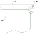
FIG. 1 is a schematic structural diagram of a liquid cooling device of a double-stator permanent magnet direct drive motor according to the invention;
fig. 2 is a schematic view of an oil supply portion;
FIG. 3 is a schematic view of an oil receiving portion;
FIG. 4 is a schematic diagram of an exchange section;
FIG. 5 is a schematic cross-sectional view of a rectangular tube;
FIG. 6 is a schematic cross-sectional view of a permanent magnet;
FIG. 7 is a cross-sectional schematic view of the ring box;
FIG. 8 is a schematic view of a radiation tube;
FIG. 9 is an enlarged schematic view of the occluding plate;
FIG. 10 is a fragmentary schematic view of the ring case;
in the figure, 1, an oil pan; 2. cooling oil; 3. a motor housing; 4. an end cap; 5. a stator shaft; 6. an iron core portion; 7. a rotor portion; 8. an oil inlet pipe; 9. an oil supply unit; 10. an exchange unit; 11. an oil receiving part; 12. a heat conducting plate; 13. a flow-through assembly; 14. a return pipe; 15. sealing the cavity; 16. a first winding coil; 17. a circular hole; 18. fastening a bolt; 19. a second winding coil; 20. a first ball bearing; 21. a connecting ring; 22. a connecting disc; 23. an output shaft; 24. a second ball bearing; 25. a circular groove; 26. a ring-shaped case; 27. a rectangular hole; 28. a radiation tube; 29. an oil transfer hole; 30. an outer ring; 31. an inner ring; 32. sealing the bearing I; 33. a second sealing bearing; 34. an annular chamber; 35. an oil delivery passage; 36. a permanent magnet; 37. a helical coil; 38. a rectangular tube; 39. a plugging plate; 40. a torsion spring; 41. a first clapboard; 42. a third sealed bearing; 43. a second clapboard; 44. a fourth sealing bearing; 45. a heat sink.
Detailed Description
In order to make the aforementioned objects, features and advantages of the present invention more comprehensible, embodiments accompanying figures are described in detail below. In the following description, numerous specific details are set forth in order to provide a thorough understanding of the present invention. This invention may, however, be embodied in many different forms and should not be construed as limited to the embodiments set forth herein.
The embodiment of the present application provides a liquid cooling device for a double-stator permanent magnet direct drive motor, please refer to fig. 1-10: the oil pan cooling device comprises an oil pan 1, cooling oil 2, a motor shell 3 and end covers 4, wherein the end covers 4 are positioned on two sides of the motor shell 3, the cooling oil 2 is positioned in the oil pan 1, the motor shell 3 is installed on the oil pan 1, a double-stator driving mechanism is arranged in the motor shell 3, and a passive oil cooling mechanism is installed on the double-stator driving mechanism;
the double-stator driving mechanism comprises a stator shaft 5, an iron core part 6 and a rotor part 7, wherein the iron core part 6 is provided with two groups, one group is positioned at the outer side of the rotor part 7 and fixedly connected with the motor shell 3, the other group is positioned at the inner side of the rotor part 7 and fixedly connected with the stator shaft 5, and the stator shaft 5 is fixedly connected with the end cover 4; the rotor part 7 is rotationally connected with the stator shaft 5;
the passive oil cooling mechanism comprises an oil inlet pipe 8, an oil supply part 9, an exchange part 10 and an oil receiving part 11, wherein the oil supply part 9 is arranged at one end of the stator shaft 5, the oil receiving part 11 is arranged at the other end of the stator shaft 5, the exchange part 10 is arranged on the rotor part 7, and the cooling oil 2 flows back into the oil pan 1 through the oil supply part 9, the exchange part 10 and the oil receiving part 11;
the oil supply part 9 radially divides the cooling oil 2 into the exchange part 10, one end of the oil supply part 9 is fixedly connected with the stator shaft 5, and the other end of the oil supply part 9 is fixedly connected with the exchange part 10;
the exchange part 10 comprises a heat conduction plate 12 and a circulation component 13, two ends of the heat conduction plate 12 are fixedly connected with the rotor part 7, the distance between one end of the heat conduction plate 12 and the stator shaft 5 is larger than that between the other end of the heat conduction plate 12 and the stator shaft 5, and the circulation component 13 is positioned on one side of the heat conduction plate 12 and is parallel to the heat conduction plate 12; the circulation assembly 13 is used for cooling oil 2 circulation;
the oil receiver 11 includes a return pipe 14 and a seal chamber 15, and the cooling oil 2 is discharged from the exchanger 10 into the seal chamber 15 and returned to the oil pan 1 through the return pipe 14.
In practical application, the device is provided with a first winding coil 16 and a second winding coil 19 which respectively correspond to an inner ring and an outer ring of the rotor part 7, at the moment, the rotor part 7 has two stress surfaces when rotating, so that power is improved, a terminal of the second winding coil 19 can be connected through the motor shell 3, the terminal of the first winding coil 16 can penetrate out of the center of the stator shaft 5 and is communicated with the outside through an electric slip ring, and when the first winding coil 16 and the second winding coil 19 are electrified, the rotor part 7 can be driven to rotate by electromagnetic induction;
before the device is used, enough cooling oil 2 is added into the oil pan 1; when the rotor part 7 rotates, one end of the oil supply part 9 and the exchange part 10 are driven to rotate, when the exchange part 10 rotates, the cooling oil 2 on the exchange part 10 generates a centripetal force, and right, because the distance between one end of the heat conduction plate 12 and the stator shaft 5 is greater than that between the other end of the heat conduction plate 12 and the stator shaft 5, the circulation component 13 is arranged on one side of the heat conduction plate 12 and parallel to the heat conduction plate 12, under the action of centrifugal force, the cooling oil 2 flows from one end of the heat conduction plate 12 close to the stator shaft 5 to one end of the heat conduction plate 12 far away from the stator shaft 5, the rotating speed is higher, the centrifugal force is higher, the cooling oil flow speed is higher, and finally the cooling oil is discharged from one end of the exchange part 10 and directly enters the oil receiving part 11; (when the first rotation is performed, the cooling oil 2 needs to be manually injected into the oil supply part 9 and the exchange part 10 by means of external oil injection equipment);
after the cooling oil 2 enters the sealed cavity 15, because the space is suddenly enlarged, the friction between the cooling oil and the rotor part 7 is suddenly disappeared, the cooling oil loses the centripetal force and decelerates, and is converged at the lower end of the sealed cavity 15 under the action of gravity and finally discharged into the oil pan 1, as shown in fig. 1, the circulation direction of the cooling oil 1 is anticlockwise, and a condensation heat exchange device can be arranged on one side of the oil pan 1, so that the cooling effect is further improved;
when the cooling oil 2 flows from the exchanging part 10 to the oil collecting part 10, negative pressure is generated at the right end of the exchanging part 10, so that the cooling oil in the oil supply part 9 is forced to flow to the exchanging part 10, and the siphon effect is realized; when the rotor part 7 continuously rotates, the cooling oil 2 can be continuously driven to flow through the exchange part 10, and the cooling oil 2 can take away the redundant heat, so that the purpose of cooling is achieved.
Referring to the description of fig. 1 and 2, the core portion 6 includes a first winding coil 16 mounted on an inner ring of the motor housing 3; a circular hole 17 is formed in the side surface of the end cover 4, the stator shaft 5 penetrates through the circular hole 17 and extends into the motor shell 3, a fastening bolt 18 is installed at one end of the stator shaft 5, the stator shaft 5 is fixedly connected with the end cover 4 through the fastening bolt 18, and a second winding coil 19 is installed on the side surface of the stator shaft 5.
In practical application, the first winding coil 16 is mounted on the inner side of the motor housing 3 and used for driving the outer side surface of the rotor part 7, and the second winding coil 19 is mounted on the outer surface of the stator shaft 5 and used for driving the inner side surface of the rotor part 7; when the motor is assembled, the stator shaft 5 can penetrate through the circular hole 17, and then the stator shaft 5 and the end cover 4 are fixedly connected through the fastening bolt 18, so that the stability of the stator shaft 5 is improved.
Referring to the attached drawings 1, 2, 3 and 4 of the specification, the rotor part 7 comprises ball bearings 20 arranged at two ends of the stator shaft 5, a connecting ring 21 is arranged on the outer ring of each ball bearing 20, a connecting disc 22 is arranged on the annular side surface of the connecting ring 21, an output shaft 23 is arranged in the center of the connecting disc 22, one output shaft 23 is arranged, and a ball bearing 24 is arranged between the output shaft 23 and the motor shell 3.
In practical application, the connection ring 21 and the connection disc 22 can stably rotate under the action of the ball bearing i 20, when the winding coil i 16 and the winding coil ii 19 are electrified to drive the permanent magnet 36 to rotate, the permanent magnet 36 drives the exchange part 10, the connection disc 22 and the connection ring 21 to rotate, and the connection ring 21 on one side drives the output shaft 23 to rotate, so that work is done to the outside.
Referring to the attached drawings 1, 2, 3 and 4 of the specification, the oil supply part 9 comprises a circular groove 25 formed at one end of the stator shaft 5, the oil inlet pipe 8 is installed at the upper end of the oil pan 1, the lower end of the oil inlet pipe 8 is close to the bottom of the oil pan 1, and the upper end of the oil inlet pipe 8 extends into the circular groove 25; an annular box 26 is installed at one end of the stator shaft 5, the annular box 26 is fixedly connected with the stator shaft 5, a rectangular hole 27 is formed in the side surface of the stator shaft 5, a radiation pipe 28 is installed between the annular box 26 and the oil inlet pipe 8, the radiation pipe 28 penetrates through the rectangular hole 27, and the radiation pipe 28 is communicated with the oil inlet pipe 8 and the annular box 26; the oil delivery hole 29 is formed in the side surface of the annular box 26, the outer ring 30 is installed on the end surface of the connecting disc 22, the inner ring 31 is installed on the end surface of the connecting disc 22, the first sealing bearing 32 is installed at the position of the outer ring 30 of the annular box 26, the inner ring of the first sealing bearing 32 is fixedly connected with the outer ring 30, the second sealing bearing 33 is installed on the inner ring 31 of the annular box 26, and the outer ring of the second sealing bearing 33 is fixedly connected with the inner ring 31; an annular chamber 34 is formed among the first sealing bearing 32, the second sealing bearing 33, the connecting disc 22 and the annular box 26, an oil conveying channel 35 is formed in the connecting disc 22, and the oil conveying channel 35 is communicated with the annular chamber 34.
Specifically, in practical application, when the cooling oil 2 flows from the exchanging part 10 to the oil collecting part 10, a negative pressure is generated at the right end of the exchanging part 10, so that the cooling oil in the oil supply part 9 flows to the exchanging part 10, and a siphon effect is realized, wherein a specific path is as follows; the cooling oil 2 in the oil pan 1 enters the radiation pipe 28 through the oil inlet pipe 8 and then enters the annular box 26, at the moment, the annular box 26 is filled with the cooling oil 2, the cooling oil 2 in the annular box 26 enters the annular cavity 34 through the oil conveying hole 29 and finally enters the oil conveying channel 35, the inner ring 31 and the outer ring 3 can rotate along with the rotation of the connecting disc 22, and the cooling oil 2 can be conveyed into the oil conveying channel 35 while the inner ring 31 and the outer ring 3 rotate under the action of the first sealing bearing 32 and the second sealing bearing 33;
referring to the accompanying drawings 1 and 6, the exchanging part 10 further includes permanent magnets 36 installed at one side of the connecting disc 22, the permanent magnets 36 and the heat conducting plates 12 are alternately arranged and annularly arranged, and both ends of the heat conducting plates 12 are fixedly connected with the connecting disc 22, respectively.
In practical application, the permanent magnet 36 is provided with a plurality of closely arranged rings, when the first winding coil 16 and the second winding coil 19 are electrified, the permanent magnet 36 can be driven to rotate by electromagnetic induction, and the heat conducting plate 12 is positioned in a gap between the permanent magnet 36 and the permanent magnet 36, so that heat can be dissipated conveniently.
Referring to the description attached fig. 1 and the description attached fig. 3 of the first embodiment of the circulation component 13, the circulation component 13 is a spiral coil 37, the spiral coil 37 is wound and connected with the heat conducting plate 12, one end of the spiral coil 37 is communicated with the oil transportation channel 35, and the other end of the spiral coil 37 penetrates through the connecting disc 22 and extends into the sealed cavity 15.
In practical application, the cooling oil 2 discharged from the oil conveying channel 35 enters the spiral coil 37, and the spiral coil 37 is wound and connected with the heat conducting plate 12, so that the cooling oil 2 can be more fully contacted with the heat conducting plate 12, the heat exchange time and the heat exchange area are prolonged, and the heat can be taken away conveniently; and finally out the other end of the spiral coil 37;
in the second embodiment of the circulation component 13, referring to fig. 1 and fig. 4 of the specification, the circulation component 13 is a rectangular tube 38, one end of the rectangular tube 38 is connected with the heat conducting plate 12, one end of the rectangular tube 38 is communicated with the oil delivery channel 35, the other end of the rectangular tube 38 passes through the connecting disc 22 and extends into the sealed cavity 15, and a heat dissipation plate 45 is mounted on the side wall of the rectangular tube 38.
In practical application, the cooling oil 2 discharged from the oil delivery channel 35 enters the rectangular tube 38, and the heat dissipation plate 45 divides the inner cavity of the rectangular tube 38 into a plurality of parts, so that the heat exchange area is increased, the flow rate of the cooling oil 2 can be increased, and the heat exchange efficiency is improved.
Referring to the attached drawings 1, 3, 4 and 9 in the specification, a plugging plate 39 is installed at one end of the flow module 13 extending into the sealed cavity 15, the plugging plate 39 is hinged with the flow module 13, a torsion spring 40 is installed between the plugging plate 39 and the flow module 13, and the plugging plate 39 and the flow module 13 are in a fit state.
In practical application, in order to avoid the occurrence of cavitation in the oil supply part 9 and the exchange part 10 and the influence on siphon quality, when the exchange part 10 does not rotate, the blocking plate 39 is attached to the oil outlet end of the circulation assembly 13 through the action of the torsion spring 40, and at the moment, the cooling oil 2 in the oil supply part 9 and the exchange part 10 is in a static state, so that the occurrence of cavitation is avoided;
as the rotation speed of the exchanging part 10 increases, the centrifugal force of the cooling oil 2 in the exchanging part 10 increases, and when the impact force of the cooling oil 2 is greater than the elastic force of the torsion spring 40, the blocking plate 39 is pushed open, so as to achieve the purpose of circulating the cooling oil 2.
Referring to the attached drawings 1 and 3 in the specification, the oil receiving portion 11 includes a first partition plate 41 installed at one end of the motor housing 3, a third seal bearing 42 is installed at the center of the first partition plate 41, an inner ring of the third seal bearing 42 is fixedly connected with the output shaft 23, a second partition plate 43 is installed at one side of the first partition plate 41, a fourth seal bearing 44 is installed at an inner ring of the second partition plate 43, an inner ring of the fourth seal bearing 44 is fixedly connected with the connecting disc 22, a seal cavity 15 is formed between the first partition plate 41 and the second partition plate 43, and the return pipe 14 is arranged at the lower end of the motor housing 3 and communicates the seal cavity 15 and the oil pan 1.
In practical application, the cooling oil 2 discharged through the circulating assembly 13 directly enters the sealed cavity 15 between the first partition plate 41 and the second partition plate 43, the friction between the cooling oil and the rotor portion 7 is weakened, the friction is insufficient to keep the cooling oil 2 at a high rotating speed, the cooling oil 2 decelerates and loses centripetal force, and the cooling oil 2 is collected at the lower end of the sealed cavity 15 under the action of gravity and finally discharged into the oil pan 1 through the return pipe 14 to form circulation.
Referring to fig. 1 of the drawings, the width of the second winding coil 19 is smaller than that of the first winding coil 16.
In practical application, the space of the motor housing 3 can be utilized more reasonably by arranging the second winding coil 19 and the first winding coil 16 with different widths.
The technical features of the embodiments described above may be arbitrarily combined, and for the sake of brevity, all possible combinations of the technical features in the embodiments described above are not described, but should be considered as being within the scope of the present specification as long as there is no contradiction between the combinations of the technical features.
The above embodiments only show some embodiments of the present invention, and the description is specific and detailed, but it should not be understood as the limitation of the invention patent scope, it should be noted that, for those skilled in the art, many variations and modifications can be made without departing from the concept of the present invention, and these embodiments all fall into the protection scope of the present invention. Therefore, the protection scope of the present patent should be subject to the appended claims.
In the description of the present invention, it is to be understood that the terms "central," "longitudinal," "lateral," "length," "width," "thickness," "upper," "lower," "front," "rear," "left," "right," "vertical," "horizontal," "top," "bottom," "inner," "outer," "clockwise," "counterclockwise," "axial," "radial," "circumferential," and the like are used in the orientations and positional relationships indicated in the drawings for convenience in describing the invention and to simplify the description, and are not intended to indicate or imply that the referenced device or element must have a particular orientation, be constructed and operated in a particular orientation, and are not to be considered limiting of the invention.
In the present invention, unless otherwise explicitly stated or limited, the terms "mounted," "connected," "fixed," and the like are to be construed broadly, e.g., as being permanently connected, detachably connected, or integral; can be mechanically or electrically connected; they may be directly connected or indirectly connected through intervening media, or they may be connected internally or in any other suitable relationship, unless expressly stated otherwise. The specific meanings of the above terms in the present invention can be understood by those skilled in the art according to specific situations.
In the present invention, unless otherwise expressly stated or limited, the first feature "on" or "under" the second feature may be directly contacting the first and second features or indirectly contacting the first and second features through an intermediate. Also, a first feature "on," "over," and "above" a second feature may be directly or diagonally above the second feature, or may simply indicate that the first feature is at a higher level than the second feature. A first feature "under," "beneath," and "under" a second feature may be directly under or obliquely under the second feature, or may simply mean that the first feature is at a lesser elevation than the second feature.
The above description is included in the technical recognition scope of the inventors, and does not necessarily constitute the prior art.
Claims (10)
1. A double-stator permanent magnet direct-drive motor liquid cooling device comprises an oil pan (1), cooling oil (2), a motor shell (3) and end covers (4), wherein the end covers (4) are located on two sides of the motor shell (3), the cooling oil (2) is located in the oil pan (1), and the motor shell (3) is installed on the oil pan (1), and is characterized in that a double-stator driving mechanism is arranged in the motor shell (3) and is provided with a passive oil cooling mechanism;
the double-stator driving mechanism comprises a stator shaft (5), an iron core part (6) and a rotor part (7), wherein the iron core part (6) is provided with two groups, one group is positioned at the outer side of the rotor part (7) and fixedly connected with the motor shell (3), the other group is positioned at the inner side of the rotor part (7) and fixedly connected with the stator shaft (5), and the stator shaft (5) is fixedly connected with an end cover (4); the rotor part (7) is rotationally connected with the stator shaft (5);
the passive oil cooling mechanism comprises an oil inlet pipe (8), an oil supply part (9), an exchange part (10) and an oil receiving part (11), wherein the oil supply part (9) is arranged at one end of the stator shaft (5), the oil receiving part (11) is arranged at the other end of the stator shaft (5), the exchange part (10) is arranged on the rotor part (7), and the cooling oil (2) flows back into the oil pan (1) through the oil supply part (9), the exchange part (10) and the oil receiving part (11);
the oil supply part (9) divides the cooling oil (2) into the exchange part (10) in a radial shape, one end of the oil supply part (9) is fixedly connected with the stator shaft (5), and the other end of the oil supply part (9) is fixedly connected with the exchange part (10);
the exchange part (10) comprises a heat conduction plate (12) and a circulation component (13), two ends of the heat conduction plate (12) are fixedly connected with the rotor part (7), the distance between one end of the heat conduction plate (12) and the stator shaft (5) is greater than that between the other end of the heat conduction plate (12) and the stator shaft (5), and the circulation component (13) is positioned on one side of the heat conduction plate (12) and is parallel to the heat conduction plate (12); the circulation assembly (13) is used for cooling oil (2) circulation;
the oil collecting part (11) comprises a return pipe (14) and a sealed cavity (15), and the cooling oil (2) is discharged from the exchange part (10) to enter the sealed cavity (15) and flows back to the oil pan (1) through the return pipe (14).
2. The double-stator permanent magnet direct drive motor liquid cooling device as claimed in claim 1, wherein the iron core portion (6) comprises a first winding coil (16) mounted on an inner ring of the motor housing (3); end cover (4) side surface is opened there is circular port (17), and stator shaft (5) pass circular port (17) and stretch into motor housing (3), fastening bolt (18) are installed to stator shaft (5) one end, and stator shaft (5) are through fastening bolt (18) and end cover (4) fixed connection, stator shaft (5) side surface mounting has winding coil two (19).
3. The liquid cooling device of the double-stator permanent magnet direct drive motor as claimed in claim 2, wherein the rotor portion (7) comprises a first ball bearing (20) installed at two ends of the stator shaft (5), a connecting ring (21) is installed on the outer ring of the first ball bearing (20), a connecting disc (22) is installed on the annular side surface of the connecting ring (21), an output shaft (23) is installed at the center of the connecting disc (22), one output shaft (23) is arranged, and a second ball bearing (24) is installed between the output shaft (23) and the motor shell (3).
4. The liquid cooling device for the double-stator permanent magnet direct drive motor as claimed in claim 3, wherein the oil supply part (9) comprises a circular groove (25) formed at one end of the stator shaft (5), the oil inlet pipe (8) is installed at the upper end of the oil pan (1), the lower end of the oil inlet pipe (8) is close to the bottom of the oil pan (1), and the upper end of the oil inlet pipe (8) extends into the circular groove (25); an annular box (26) is installed at one end of the stator shaft (5), the annular box (26) is fixedly connected with the stator shaft (5), a rectangular hole (27) is formed in the side surface of the stator shaft (5), a radiation tube (28) is installed between the annular box (26) and the oil inlet tube (8), the radiation tube (28) penetrates through the rectangular hole (27), and the radiation tube (28) is communicated with the oil inlet tube (8) and the annular box (26); an oil conveying hole (29) is formed in the side surface of the annular box (26), an outer ring (30) is installed on the end surface of the connecting disc (22), an inner ring (31) is installed on the end surface of the connecting disc (22), a first sealing bearing (32) is installed at the position of the outer ring (30) of the annular box (26), the inner ring of the first sealing bearing (32) is fixedly connected with the outer ring (30), a second sealing bearing (33) is installed on the inner ring (31) of the annular box (26), and the outer ring of the second sealing bearing (33) is fixedly connected with the inner ring (31); an annular cavity (34) is formed among the first sealing bearing (32), the second sealing bearing (33), the connecting disc (22) and the annular box (26), an oil conveying channel (35) is formed in the connecting disc (22), and the oil conveying channel (35) is communicated with the annular cavity (34).
5. The liquid cooling device of the double-stator permanent magnet direct drive motor as claimed in claim 4, wherein the exchange part (10) further comprises permanent magnets (36) installed on one side of the connecting disc (22), the permanent magnets (36) and the heat conducting plates (12) are alternately arranged and annularly arranged, and two ends of the heat conducting plates (12) are respectively and fixedly connected with the connecting disc (22).
6. The liquid cooling device of the double-stator permanent magnet direct drive motor as claimed in claim 5, wherein the circulation component (13) is a spiral coil (37), the spiral coil (37) is wound and connected with the heat conducting plate (12), one end of the spiral coil (37) is communicated with the oil delivery channel (35), and the other end of the spiral coil (37) penetrates through the connecting disc (22) and extends into the sealed cavity (15).
7. The liquid cooling device of the double-stator permanent magnet direct drive motor as claimed in claim 5, wherein the circulation component (13) is a rectangular tube (38), one end of the rectangular tube (38) is connected with the heat conducting plate (12), one end of the rectangular tube (38) is communicated with the oil delivery channel (35), the other end of the rectangular tube (38) penetrates through the connecting disc (22) and extends into the sealed cavity (15), and the side wall of the rectangular tube (38) is provided with a heat dissipation plate (45).
8. The liquid cooling device of the double-stator permanent magnet direct drive motor as claimed in claim 6 or 7, wherein a blocking plate (39) is installed at one end of the circulation assembly (13) extending into the sealed cavity (15), the blocking plate (39) is hinged to the circulation assembly (13), a torsion spring (40) is installed between the blocking plate (39) and the circulation assembly (13), and the blocking plate (39) and the circulation assembly (13) are in a fit state.
9. The liquid cooling device of the double-stator permanent magnet direct-drive motor as claimed in claim 8, wherein the oil receiving portion (11) comprises a first partition plate (41) installed at one end of the motor housing (3), a third seal bearing (42) is installed at the center of the first partition plate (41), an inner ring of the third seal bearing (42) is fixedly connected with the output shaft (23), a second partition plate (43) is installed on one side of the first partition plate (41), a third seal bearing (42) is installed on an inner ring of the second partition plate (43), an inner ring of the third seal bearing (42) is fixedly connected with the connecting disc (22), a seal cavity (15) is formed between the first partition plate (41) and the second partition plate (43), and the return pipe (14) is arranged at the lower end of the motor housing (3) and communicated with the seal cavity (15) and the oil pan (1).
10. The liquid cooling device for the double-stator permanent magnet direct drive motor as claimed in claim 9, wherein the width of the second winding coil (19) is smaller than that of the first winding coil (16).
Priority Applications (1)
| Application Number | Priority Date | Filing Date | Title |
|---|---|---|---|
| CN202211671858.1A CN115664117B (en) | 2022-12-26 | 2022-12-26 | Liquid cooling device of double-stator permanent magnet direct drive motor |
Applications Claiming Priority (1)
| Application Number | Priority Date | Filing Date | Title |
|---|---|---|---|
| CN202211671858.1A CN115664117B (en) | 2022-12-26 | 2022-12-26 | Liquid cooling device of double-stator permanent magnet direct drive motor |
Publications (2)
| Publication Number | Publication Date |
|---|---|
| CN115664117A true CN115664117A (en) | 2023-01-31 |
| CN115664117B CN115664117B (en) | 2023-03-03 |
Family
ID=85022611
Family Applications (1)
| Application Number | Title | Priority Date | Filing Date |
|---|---|---|---|
| CN202211671858.1A Active CN115664117B (en) | 2022-12-26 | 2022-12-26 | Liquid cooling device of double-stator permanent magnet direct drive motor |
Country Status (1)
| Country | Link |
|---|---|
| CN (1) | CN115664117B (en) |
Cited By (1)
| Publication number | Priority date | Publication date | Assignee | Title |
|---|---|---|---|---|
| CN115995910A (en) * | 2023-03-23 | 2023-04-21 | 河北乾顺节能科技有限公司 | Active ventilation and heat dissipation device of outer rotor motor |
Citations (13)
| Publication number | Priority date | Publication date | Assignee | Title |
|---|---|---|---|---|
| US20050194847A1 (en) * | 2002-09-24 | 2005-09-08 | Siemens Aktiengesellschaft | Electric machine with thermosiphon-type cooling system |
| JP2007020337A (en) * | 2005-07-08 | 2007-01-25 | Komatsu Ltd | Cooling structure for electric motor, and construction machine vehicle provided with the electric motor |
| US20070069593A1 (en) * | 2003-05-26 | 2007-03-29 | Valeo Equipement Electriquemoteur | Rotating electrical machine, such as an alternator, particularly for an automobile |
| CN102104297A (en) * | 2011-03-15 | 2011-06-22 | 李金东 | Internal circulation oil-cooled permanent-magnet direct-current motor |
| CN102570745A (en) * | 2012-01-05 | 2012-07-11 | 陈国宝 | Oil magnetic-suspension double-stator high-efficiency motor |
| CN205160261U (en) * | 2015-11-24 | 2016-04-13 | 东莞市长锦成电器有限公司 | Double -stator motor |
| WO2016206342A1 (en) * | 2015-06-23 | 2016-12-29 | 戴杰 | Self-circulation liquid-cooled permanent magnet motor |
| CN108512363A (en) * | 2018-04-10 | 2018-09-07 | 浙江兴轮电驱动有限公司 | A kind of oil-cooled motor |
| CN113162300A (en) * | 2021-04-28 | 2021-07-23 | 中国第一汽车股份有限公司 | Motor cooling system, motor and vehicle |
| CN113794331A (en) * | 2021-09-10 | 2021-12-14 | 李绵军 | Oil-gas double-cooling motor |
| CN113809893A (en) * | 2021-09-23 | 2021-12-17 | 河北新四达电机股份有限公司 | Double-stator permanent magnet synchronous motor |
| WO2022206804A1 (en) * | 2021-03-31 | 2022-10-06 | 比亚迪股份有限公司 | Motor system and vehicle having same |
| US20220360133A1 (en) * | 2021-05-07 | 2022-11-10 | Magna Pt B.V. & Co. Kg | Electric machine with rotor cooling |
-
2022
- 2022-12-26 CN CN202211671858.1A patent/CN115664117B/en active Active
Patent Citations (13)
| Publication number | Priority date | Publication date | Assignee | Title |
|---|---|---|---|---|
| US20050194847A1 (en) * | 2002-09-24 | 2005-09-08 | Siemens Aktiengesellschaft | Electric machine with thermosiphon-type cooling system |
| US20070069593A1 (en) * | 2003-05-26 | 2007-03-29 | Valeo Equipement Electriquemoteur | Rotating electrical machine, such as an alternator, particularly for an automobile |
| JP2007020337A (en) * | 2005-07-08 | 2007-01-25 | Komatsu Ltd | Cooling structure for electric motor, and construction machine vehicle provided with the electric motor |
| CN102104297A (en) * | 2011-03-15 | 2011-06-22 | 李金东 | Internal circulation oil-cooled permanent-magnet direct-current motor |
| CN102570745A (en) * | 2012-01-05 | 2012-07-11 | 陈国宝 | Oil magnetic-suspension double-stator high-efficiency motor |
| WO2016206342A1 (en) * | 2015-06-23 | 2016-12-29 | 戴杰 | Self-circulation liquid-cooled permanent magnet motor |
| CN205160261U (en) * | 2015-11-24 | 2016-04-13 | 东莞市长锦成电器有限公司 | Double -stator motor |
| CN108512363A (en) * | 2018-04-10 | 2018-09-07 | 浙江兴轮电驱动有限公司 | A kind of oil-cooled motor |
| WO2022206804A1 (en) * | 2021-03-31 | 2022-10-06 | 比亚迪股份有限公司 | Motor system and vehicle having same |
| CN113162300A (en) * | 2021-04-28 | 2021-07-23 | 中国第一汽车股份有限公司 | Motor cooling system, motor and vehicle |
| US20220360133A1 (en) * | 2021-05-07 | 2022-11-10 | Magna Pt B.V. & Co. Kg | Electric machine with rotor cooling |
| CN113794331A (en) * | 2021-09-10 | 2021-12-14 | 李绵军 | Oil-gas double-cooling motor |
| CN113809893A (en) * | 2021-09-23 | 2021-12-17 | 河北新四达电机股份有限公司 | Double-stator permanent magnet synchronous motor |
Cited By (2)
| Publication number | Priority date | Publication date | Assignee | Title |
|---|---|---|---|---|
| CN115995910A (en) * | 2023-03-23 | 2023-04-21 | 河北乾顺节能科技有限公司 | Active ventilation and heat dissipation device of outer rotor motor |
| CN115995910B (en) * | 2023-03-23 | 2023-06-02 | 河北乾顺节能科技有限公司 | Active ventilation and heat dissipation device of outer rotor motor |
Also Published As
| Publication number | Publication date |
|---|---|
| CN115664117B (en) | 2023-03-03 |
Similar Documents
| Publication | Publication Date | Title |
|---|---|---|
| WO2022037263A1 (en) | Oil-water combined cooling electric motor system, and vehicle | |
| WO2018103307A1 (en) | Motor rotor support frame and motor | |
| WO2016206342A1 (en) | Self-circulation liquid-cooled permanent magnet motor | |
| CN105065290B (en) | Brushless direct-current magnetic water pump | |
| CN115664117B (en) | Liquid cooling device of double-stator permanent magnet direct drive motor | |
| CN113381531A (en) | Stator cooling structure and motor with same | |
| CN114629297B (en) | Liquid cooling motor | |
| CN204258598U (en) | A kind of radiator structure of power cell and rack | |
| CN211508791U (en) | Motor casing and motor using same | |
| CN216056503U (en) | Easy radiating disk motor stator | |
| CN115498316A (en) | Passive heat dissipation device of lithium ion battery | |
| KR102176370B1 (en) | Electric motor | |
| CN113555996A (en) | High-efficiency high-power electronic water pump | |
| CN109742903B (en) | Vehicle, hub motor heat dissipation system thereof and hub motor heat dissipation method | |
| CN218771544U (en) | Bearing frame, motor and unmanned aerial vehicle of motor | |
| CN218243262U (en) | Efficient heat-dissipation permanent magnet direct-drive motor | |
| CN114337111B (en) | Internal circulation evaporative cooling motor cooling structure | |
| CN210958000U (en) | High-speed motor casing for electric vehicle | |
| US11415129B2 (en) | High-pressure pump | |
| CN102270903A (en) | Through liquid-cooling self-circulation driving motor | |
| CN218071234U (en) | Internal and external circulation type cooling device for double side walls of hub motor | |
| CN105743268B (en) | A kind of aeration structure and method by cooling medium consumption inside and outside loss ratio distribution | |
| CN212177516U (en) | Heat dissipation device of shield pump | |
| CN221103151U (en) | Circulation radiator suitable for water pump motor | |
| CN220672671U (en) | Liquid cooling battery box |
Legal Events
| Date | Code | Title | Description |
|---|---|---|---|
| PB01 | Publication | ||
| PB01 | Publication | ||
| SE01 | Entry into force of request for substantive examination | ||
| SE01 | Entry into force of request for substantive examination | ||
| GR01 | Patent grant | ||
| GR01 | Patent grant |