CN115608564A - A six-component gluing device - Google Patents
A six-component gluing device Download PDFInfo
- Publication number
- CN115608564A CN115608564A CN202211289990.6A CN202211289990A CN115608564A CN 115608564 A CN115608564 A CN 115608564A CN 202211289990 A CN202211289990 A CN 202211289990A CN 115608564 A CN115608564 A CN 115608564A
- Authority
- CN
- China
- Prior art keywords
- glue
- mixing chamber
- valve
- seat
- main shaft
- Prior art date
- Legal status (The legal status is an assumption and is not a legal conclusion. Google has not performed a legal analysis and makes no representation as to the accuracy of the status listed.)
- Pending
Links
Images


Classifications
-
- B—PERFORMING OPERATIONS; TRANSPORTING
- B05—SPRAYING OR ATOMISING IN GENERAL; APPLYING FLUENT MATERIALS TO SURFACES, IN GENERAL
- B05C—APPARATUS FOR APPLYING FLUENT MATERIALS TO SURFACES, IN GENERAL
- B05C5/00—Apparatus in which liquid or other fluent material is projected, poured or allowed to flow on to the surface of the work
- B05C5/02—Apparatus in which liquid or other fluent material is projected, poured or allowed to flow on to the surface of the work the liquid or other fluent material being discharged through an outlet orifice by pressure, e.g. from an outlet device in contact or almost in contact, with the work
-
- B—PERFORMING OPERATIONS; TRANSPORTING
- B05—SPRAYING OR ATOMISING IN GENERAL; APPLYING FLUENT MATERIALS TO SURFACES, IN GENERAL
- B05C—APPARATUS FOR APPLYING FLUENT MATERIALS TO SURFACES, IN GENERAL
- B05C11/00—Component parts, details or accessories not specifically provided for in groups B05C1/00 - B05C9/00
- B05C11/10—Storage, supply or control of liquid or other fluent material; Recovery of excess liquid or other fluent material
- B05C11/1036—Means for supplying a selected one of a plurality of liquids or other fluent materials, or several in selected proportions, to the applying apparatus
Landscapes
- Coating Apparatus (AREA)
Abstract
Description
技术领域technical field
本发明属于涂胶设备技术领域,尤其涉及一种六组份涂胶装置。The invention belongs to the technical field of gluing equipment, in particular to a six-component gluing device.
背景技术Background technique
随着科技发展进步,在产品生产制造过程中对产品本身或其中的零部件进行密封时,传统的手工贴条已经逐步被机器人持涂胶装置进行现场涂胶密封所取代,这种新技术广泛应用在汽车零部件、音响制品、灯具、新能源电池行业以及光伏产业等。不同产品的密封需要对应使用符合设计要求的胶水,而现有的涂胶装置往往只能满足一种单组分或双组分胶水。即使有满足三组分胶水的混合装置也是将其中的一个组分的胶阀通过拆卸交换的方式进行操作。当需要使用更多组份的时候,只能通过再增加成套设备来完成这样不仅是企业增加成本同时还需要占用更多生产空间。With the development and progress of science and technology, when sealing the product itself or its parts during the production and manufacturing process, the traditional manual sticking has been gradually replaced by the robot holding the gluing device for on-site gluing and sealing. This new technology is widely used. It is used in auto parts, audio products, lamps, new energy battery industry and photovoltaic industry, etc. The sealing of different products requires corresponding use of glue that meets the design requirements, and the existing gluing device can only meet one kind of one-component or two-component glue. Even if there is a mixing device that meets the three-component glue, the glue valve of one of the components is operated by disassembling and exchanging. When more components need to be used, it can only be done by adding complete sets of equipment. This not only increases the cost of the enterprise but also takes up more production space.
发明内容Contents of the invention
为了解决上述现有技术中存在的技术问题,本发明提供一种六组份涂胶装置,该装置采用轴向旁通供胶阀,在满足小体积的同时保证胶水的顺畅供给;六个胶阀分别对应胶水的六组分,如果是双组分胶水就是三种胶水,如果有共用其中一种组分时,可以满足更多种胶水。当使用其中一种胶水时其他胶阀均关闭;这样就可以使用一种涂胶装置满足三种或三种以上的胶水的涂胶作业。In order to solve the above-mentioned technical problems in the prior art, the present invention provides a six-component gluing device, which adopts an axial bypass glue supply valve to ensure the smooth supply of glue while satisfying the small volume; The valves correspond to the six components of the glue. If it is a two-component glue, it is three kinds of glue. If one of the components is shared, more kinds of glue can be satisfied. When one of the glues is used, the other glue valves are all closed; in this way, one gluing device can be used to meet the gluing operations of three or more glues.
技术方案如下:The technical solution is as follows:
一种六组份涂胶装置,包括:A six-component gluing device, including:
主轴模块和若干胶阀模块,所述胶阀模块可拆卸地、均匀分布在所述主轴模块;a main shaft module and several glue valve modules, the glue valve modules are detachably and evenly distributed on the main shaft module;
所述主轴模块包括:The spindle module includes:
伺服电机,通过电机安装板安装在主轴箱上;所述伺服电机输出轴通过联轴器与主轴连接;The servo motor is installed on the main shaft box through the motor mounting plate; the output shaft of the servo motor is connected with the main shaft through a coupling;
主轴通过螺母、轴承固定在活塞上;The main shaft is fixed on the piston through nuts and bearings;
混合室,与所述主轴箱连接;a mixing chamber connected to the headstock;
封盖,与所述混合室连接形成腔室;a cover connected to the mixing chamber to form a chamber;
搅拌系统,安装在所述混合室下方,所述主轴与所述搅拌系统连接;Stirring system installed under the mixing chamber, the main shaft is connected with the stirring system;
气动接头A,安装在所述混合室上;Pneumatic joint A, installed on the mixing chamber;
调速阀和气动接头B,分别与所述活塞连接;The speed regulating valve and the pneumatic joint B are respectively connected with the piston;
接头,与加长接头连接,所述加长接头与所述混合室连接;a joint connected to an extension joint connected to the mixing chamber;
内套,其上的槽口通过导向轴固定在旋转导套内,所述内套上设置有锁定螺丝和弹簧柱销;An inner sleeve, the notch on which is fixed in the rotating guide sleeve through a guide shaft, and a locking screw and a spring pin are arranged on the inner sleeve;
所述胶阀模块包括:The valve module includes:
接头,安装在后尾座上;Connector, installed on the rear tailstock;
中段座,与所述后尾座连接;the middle seat is connected with the rear tailstock;
阀座,与所述中段座连接;a valve seat connected to the middle seat;
所述后尾座内设气缸活塞,弹簧安装在尾座与气缸活塞中间;A cylinder piston is arranged in the rear tailstock, and a spring is installed between the tailstock and the cylinder piston;
所述阀座内设阀针,所述阀针穿过所述中段座、延伸至所述后尾座,且与所述气缸活塞连接;A valve needle is arranged inside the valve seat, and the valve needle passes through the middle seat, extends to the rear tail seat, and is connected with the cylinder piston;
用于给气缸活塞提供压缩空气的气动接头C,所述气动接头C与所述后尾座连接。A pneumatic joint C for providing compressed air to the cylinder piston, the pneumatic joint C is connected with the rear tailstock.
进一步的,所述胶阀模块的数量为,所述胶阀模块通过压片与所述混合室连接。Further, the quantity of the glue valve module is as follows, and the glue valve module is connected with the mixing chamber through a pressing piece.
进一步的,还包括唇形密封,通过衬套和轴承压盖固定在所述混合室内。Further, it also includes a lip seal, which is fixed in the mixing chamber through a bush and a bearing cover.
进一步的,还包括用于检测混合室温度以配合冷却液保证混合室恒定温度的温度传感器,安装在所述混合室上。Further, it also includes a temperature sensor for detecting the temperature of the mixing chamber to cooperate with the cooling liquid to ensure a constant temperature of the mixing chamber, installed on the mixing chamber.
进一步的,还包括:Further, it also includes:
透明按钮,通过锁紧柱连接主轴箱;The transparent button is connected to the headstock through the locking column;
遮盖板,通过固定片A和固定片B与主轴箱连接;The cover plate is connected with the headstock through the fixed piece A and the fixed piece B;
安装支架,安装在所述主轴箱上;a mounting bracket installed on the headstock;
进一步的,所述活塞外圈安装星型密封圈和密封圈A,所述加长接头通过水阀压板A与所述混合室连接。Further, a star-shaped sealing ring and a sealing ring A are installed on the outer ring of the piston, and the extension joint is connected to the mixing chamber through the water valve pressure plate A.
进一步的,所述后尾座和中段座之间设置O型圈A、O型圈B、内套管;Further, an O-ring A, an O-ring B, and an inner sleeve are arranged between the rear tailstock and the middle seat;
所述阀针外围设置隔套和星型密封圈。A spacer and a star-shaped sealing ring are arranged on the periphery of the valve needle.
进一步的,所述搅拌系统包括:Further, the stirring system includes:
搅拌杯,其下方连接喷嘴;Stirring cup, the nozzle is connected below it;
搅拌叶,内设与所述搅拌杯中,所述搅拌叶与所述主轴连接。Stirring blades are installed in the stirring cup, and the stirring blades are connected to the main shaft.
进一步的,还包括密封圈B和密封圈C,所述封盖和混合室之间设置所述密封圈B和密封圈C。Further, a sealing ring B and a sealing ring C are also included, and the sealing ring B and the sealing ring C are arranged between the cover and the mixing chamber.
进一步的,所述阀座与中段座之间设置密封圈D,密封圈E套装在所述阀座上。Further, a sealing ring D is provided between the valve seat and the middle seat, and the sealing ring E is sleeved on the valve seat.
本发明的有益效果是:The beneficial effects of the present invention are:
本发明所述的具有以下有益效果:The present invention has the following beneficial effects:
(1)实现六阀集成功能:(1) Realize the integrated function of six valves:
本发明采用特殊的轴向旁通供胶阀,在满足小体积的同时保证胶水的顺畅供给。六个胶阀分别对应胶水的六组分,如果是双组分胶水就是三种胶水,如果有共用其中一种组分时,可以满足更多种胶水。当使用其中一种胶水时其他胶阀均关闭。这样就可以使用一种涂胶装置满足三种或三种以上的胶水的涂胶作业;The invention adopts a special axial bypass glue supply valve to ensure the smooth supply of glue while satisfying the small volume. The six glue valves correspond to the six components of the glue. If it is a two-component glue, it is three kinds of glue. If one of the components is shared, more kinds of glue can be satisfied. When one of the glues is used, the other glue valves are closed. In this way, one gluing device can be used to meet the gluing operations of three or more glues;
(2)胶阀、水阀快拆结构设计:(2) Quick release structure design of glue valve and water valve:
只需松开两颗固定螺丝不需要完全拆下,滑动固定片就可以把胶阀水阀从主体中拔出;Just loosen the two fixing screws without completely removing them, and slide the fixing piece to pull the glue valve water valve out of the main body;
(3)搅拌叶快拆结构设计:(3) Quick-release structure design of mixing blade:
拆解时只需要按住拆解透明按钮即可锁定旋转主轴,这时手动旋转搅拌叶即可完成拆解作业。When disassembling, you only need to press and hold the dismantling transparent button to lock the rotating main shaft, and then manually rotate the stirring blade to complete the disassembly operation.
(4)轴动开闭胶间隙的快速调整结构设计:(4) The quick adjustment structure design of the axial movement to open and close the rubber gap:
更方便操作人员调节胶水的打开和关闭间距的大小,采用内部滑槽结构,配合外部激光刻蚀的刻度;调整轴动间隙的时候只需要松开锁紧螺丝,拨动调整杆即可完成轴动间隙调整作业。It is more convenient for the operator to adjust the size of the opening and closing distance of the glue. The internal chute structure is used to cooperate with the external laser-etched scale; when adjusting the shaft movement gap, only need to loosen the locking screw and move the adjustment lever to complete the shaft movement. Adjustment of dynamic gap.
附图说明Description of drawings
为了更清楚地说明本发明实施方式的技术方案,下面将结合附图和详细实施方式对本发明进行详细说明,显而易见地,下面描述中的附图仅仅是本发明的一些实施方式,对于本领域普通技术人员来讲,在不付出创造性劳动性的前提下,还可以根据这些附图获得其它的附图。其中:In order to more clearly illustrate the technical solutions of the embodiments of the present invention, the present invention will be described in detail below in conjunction with the accompanying drawings and detailed embodiments. Obviously, the accompanying drawings in the following description are only some embodiments of the present invention. Technical personnel can also obtain other drawings based on these drawings without paying creative labor. in:
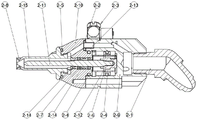
图1为本发明总体示意图;Fig. 1 is the overall schematic diagram of the present invention;
图2为本发明的轴向胶阀剖视结构示意图;Fig. 2 is a schematic cross-sectional structure diagram of the axial rubber valve of the present invention;
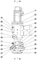
图3为本发明的主轴部分结构示意图;Fig. 3 is a schematic diagram of the structure of the main shaft part of the present invention;
图4为图3的D-D剖视图;Fig. 4 is a D-D sectional view of Fig. 3;
图5为本发明搅拌杯搅拌叶部分结构示意图;Fig. 5 is a structural schematic diagram of part of the stirring blade of the stirring cup of the present invention;
图中附图标记如下:1.唇形密封,2.气动接头A,3.轴承,4.伺服电机,5.螺母,6.弹簧,7.弹簧柱销,8.锁定螺丝,10.密封圈A,11.星型密封圈A,13.密封圈B,14.密封圈C,15.接头,16.调速阀,17.气动接头B,18.垫圈,19.混合室,20.封盖,21.加长接头,22.电机安装板,23.压片,24.衬套,25.轴承压盖,26.主轴箱,27.主轴,28.温度传感器,29.水阀压板A,31.导向轴,32.旋转导套,33.活塞,34.联轴器,35.内套,37.锁紧柱,38.透明按钮,40.遮盖板,41.固定片A,42.安装支架,43.固定片B,2-1.接头,2-2.O型圈A,2-3.气动接头C,2-4.O型圈B,2-5.密封圈D,2-6.弹簧,2-7.星型密封圈B,2-8.密封圈E,2-9.后尾座,2-10.中段座,2-11.阀针,2-12.气缸活塞,2-13.内套管,2-14.隔套,2-15.阀座,3-1.搅拌杯,3-2.喷嘴,3-3.搅拌叶。The reference signs in the figure are as follows: 1. Lip seal, 2. Pneumatic joint A, 3. Bearing, 4. Servo motor, 5. Nut, 6. Spring, 7. Spring pin, 8. Lock screw, 10. Seal Ring A, 11. Star seal ring A, 13. Seal ring B, 14. Seal ring C, 15. Joint, 16. Speed control valve, 17. Pneumatic joint B, 18. Gasket, 19. Mixing chamber, 20. Cover, 21. Extended joint, 22. Motor mounting plate, 23. Pressure plate, 24. Bushing, 25. Bearing gland, 26. Headstock, 27. Main shaft, 28. Temperature sensor, 29. Water valve pressure plate A , 31. Guide shaft, 32. Rotating guide sleeve, 33. Piston, 34. Coupling, 35. Inner sleeve, 37. Locking column, 38. Transparent button, 40. Cover plate, 41. Fixed piece A, 42 .Installation bracket, 43. Fixed piece B, 2-1. Joint, 2-2. O-ring A, 2-3. Pneumatic joint C, 2-4. O-ring B, 2-5. Sealing ring D, 2-6. Spring, 2-7. Star seal ring B, 2-8. Seal ring E, 2-9. Rear tail seat, 2-10. Middle seat, 2-11. Valve pin, 2-12. Cylinder piston, 2-13. Inner sleeve, 2-14. Spacer, 2-15. Valve seat, 3-1. Stirring cup, 3-2. Nozzle, 3-3. Stirring blade.
具体实施方式detailed description
为了使本发明的目的、技术方案及优点更加清楚明白,以下结合附图及实施例,对本发明进行进一步详细说明。应当理解,此处所描述的具体实施例仅仅用以解释本发明,并不用于限定本发明。In order to make the object, technical solution and advantages of the present invention clearer, the present invention will be further described in detail below in conjunction with the accompanying drawings and embodiments. It should be understood that the specific embodiments described here are only used to explain the present invention, not to limit the present invention.
下面结合附图1-5对六组份涂胶装置做进一步说明。The six-component gluing device will be further described below in conjunction with accompanying drawings 1-5.
实施例1Example 1
一种六组份涂胶装置,包括:A six-component gluing device, including:
主轴模块和六组胶阀模块,所述胶阀模块可拆卸地、均匀分布在所述主轴模块;a main shaft module and six groups of glue valve modules, the glue valve modules are detachably and evenly distributed on the main shaft module;
所述主轴模块包括:The spindle module includes:
伺服电机4,通过电机安装板22安装在主轴箱26上;所述伺服电机4输出轴通过联轴器34与主轴27连接;The servo motor 4 is installed on the
主轴27通过螺母5、轴承3固定在活塞33上;The
混合室19,与所述主轴箱26连接;The mixing
封盖20,与所述混合室19连接形成腔室,并通过密封圈B13、密封圈C14保证密封;The
搅拌系统,安装在所述混合室19下方,所述主轴27与所述搅拌系统连接;A stirring system is installed below the mixing
气动接头A2,安装在所述混合室19上;Pneumatic joint A2 installed on the mixing
调速阀16和气动接头B17,分别与所述活塞33连接;The
接头15,与加长接头21连接,所述加长接头21与所述混合室19连接;The joint 15 is connected with the extension joint 21, and the extension joint 21 is connected with the mixing
内套35,其上的槽口通过导向轴31固定在旋转导套32内,锁定螺丝8固定在内套35上,可以通过六角扳手旋紧固定旋转导套32;The
弹簧柱销7,安装在内套35上;
所述胶阀模块通过压片23与所述混合室19连接。The glue valve module is connected with the mixing
还包括唇形密封1,通过衬套24和轴承压盖25固定在所述混合室19内。还包括用于检测混合室19温度以配合冷却液保证混合室19恒定温度的温度传感器28,安装在所述混合室19上。透明按钮38,通过锁紧柱37连接主轴箱26;遮盖板40,通过固定片A41和固定片B43与主轴箱26连接;安装支架42,安装在所述主轴箱26上;It also includes a
所述活塞33外圈安装星型密封圈A11及密封圈A10,所述加长接头21通过水阀压板A29与所述混合室19连接。A star-shaped sealing ring A11 and a sealing ring A10 are installed on the outer ring of the
优选地,所述搅拌系统包括:Preferably, the mixing system includes:
搅拌杯3-1,其下方连接喷嘴3-2;Stirring cup 3-1, the nozzle 3-2 is connected below it;
搅拌叶3-3,内设与所述搅拌杯中,所述搅拌叶3-3与所述主轴27连接。Stirring blades 3-3 are provided in the stirring cup, and the stirring blades 3-3 are connected to the
主轴部分由以下部分组成:伺服电机4通过电机安装板22安装在主轴箱26上。伺服电机4输出轴通过联轴器34与主轴27进行连接,主轴27被螺母5、轴承3固定在活塞33上。活塞33外圈安装星型密封圈A11,压缩气体通过调速阀16、气动接头17驱动活塞33及主轴27上下移动。内套35零件上的槽口被导向轴31固定在螺旋导套32内,内套35可以用来限制活塞33的上下移动位置,方便涂胶工艺的调整使用。The main shaft part is made up of the following parts: the servo motor 4 is installed on the
唇形密封1通过衬套24及轴承压盖25固定在混合室19内,唇形密封1可以保证主轴27旋转和上下移动的时候胶水不会进入轴承3内部。气动接头A2安装在混合室19上,冷却液会通过气动接头A2进入混合室19内部的冷却通道,温度传感器28可以检测此部分的温度配合冷却液保证此部分的恒定温度。The
接头15和加长接头21连接在混合室19上,清洗时溶剂通过接头15进入混合室19与封盖20形成的腔室内,溶剂会在腔室内均匀喷射到需要清洗的部位。透明按钮38通过锁紧柱37连接在主轴箱26内,透明按钮38可以被人手按下,按下后锁紧柱37可以锁紧主轴27,然后人工可以对安装在主轴27下的搅拌叶3-2进行拆解作业。The joint 15 and the extension joint 21 are connected to the mixing
搅拌杯搅拌叶部分由以下部分组成:搅拌杯3-1下端安装喷嘴3-2,搅拌叶3-3安装在主轴27上,搅拌杯3-1通过带缺口的螺纹安装在混合室19下端。The stirring blade part of the stirring cup is composed of the following parts: the nozzle 3-2 is installed at the lower end of the stirring cup 3-1, the stirring blade 3-3 is installed on the
更换胶阀时使用六角扳手将固定压片23的螺丝拧松,手动将压片23移动远离胶阀,手握住胶阀向远离主轴部分方向即可拔出胶阀。维护作业后将胶阀插入主轴箱部分,手动将压片23卡入胶阀上已有的卡槽,再使用六角扳手将固定压片23的螺丝拧紧即可固定。When replacing the rubber valve, use a hex wrench to loosen the screw that fixes the
调整轴动间隙时,使用六角扳手拧松锁定螺丝8,这时手动移动导向轴31并通过目测遮盖板40上的箭头图标与固定片41上有对应的激光刻度,判断是否移动到适合位置。确定位置合适后使用六角扳拧紧锁定螺丝8。When adjusting the axial clearance, use a hexagonal wrench to loosen the locking screw 8. At this time, manually move the
实施例2Example 2
本实施例作为一种单独的实施例或者是对实施例1的补充,本实施例提供一种优选的胶阀模块,所述胶阀模块包括:This embodiment is a separate embodiment or a supplement to
接头2-1,安装在后尾座2-9上;Joint 2-1 is installed on the rear tailstock 2-9;
中段座2-10,与所述后尾座2-9连接;The middle seat 2-10 is connected with the rear tailstock 2-9;
阀座2-15,与所述中段座2-10连接,中间通过密封圈D2-5保证密封,密封圈E2-8套装在阀座2-15上;The valve seat 2-15 is connected with the middle seat 2-10, and the seal is guaranteed by the sealing ring D2-5 in the middle, and the sealing ring E2-8 is set on the valve seat 2-15;
所述后尾座2-9内设气缸活塞2-12,弹簧2-6安装在后尾座2-9与气缸活塞2-12中间;The rear tailstock 2-9 is provided with a cylinder piston 2-12, and the spring 2-6 is installed between the rear tailstock 2-9 and the cylinder piston 2-12;
所述阀座2-15内设阀针2-11,所述阀针2-11穿过所述中段座2-10、延伸至所述后尾座2-9,且与所述气缸活塞2-12连接。The valve seat 2-15 is provided with a valve needle 2-11, and the valve needle 2-11 passes through the middle seat 2-10, extends to the rear tail seat 2-9, and is connected with the cylinder piston 2 -12 connections.
所述后尾座2-9和中段座2-10之间设置O型圈A2-2、O型圈B2-4、内套管2-13;所述阀针2-11外围设置隔套2-14和星型密封圈B2-7。An O-ring A2-2, an O-ring B2-4, and an inner casing 2-13 are arranged between the rear tailstock 2-9 and the middle seat 2-10; a
胶阀由以下部分组成:接头2-1安装在后尾座2-9上,后尾座2-9与中段座2-10中间通过O型圈A2-2、O型圈B2-4、内套管2-13形成密封结构。The rubber valve consists of the following parts: the joint 2-1 is installed on the rear tailstock 2-9, and the middle of the rear tailstock 2-9 and the middle seat 2-10 passes through the O-ring A2-2, the O-ring B2-4, the inner The sleeve 2-13 forms a sealed structure.
阀座2-15与阀针2-11配合动作可以完成胶水的通断控制。阀针2-11安装在气缸活塞2-12上,气缸活塞2-12外圈安装O型圈B2-4并通过气动接头C2-3通过的压缩空气完成前后伸缩移动,所述气动接头C2-3连接电磁阀,通过外部控制单元对电磁阀进行控制。星型密封圈B2-7及隔套2-14对阀针2-11进行密封及导向。阀座2-15中间有一个胶水通路,当阀针2-11缩回时阀座2-15中间孔胶水可以流动,当2-11阀针伸出时将阀座2-15阀座中间胶水通路关闭,从而控制胶水关闭。The valve seat 2-15 cooperates with the valve needle 2-11 to complete the on-off control of the glue. The valve needle 2-11 is installed on the cylinder piston 2-12, and the outer ring of the cylinder piston 2-12 is equipped with an O-ring B2-4, and the compressed air passing through the pneumatic joint C2-3 completes the forward and backward telescopic movement, and the pneumatic joint C2- 3 Connect the solenoid valve, and control the solenoid valve through an external control unit. The star seal ring B2-7 and the spacer 2-14 seal and guide the valve needle 2-11. There is a glue channel in the middle of the valve seat 2-15. When the valve needle 2-11 is retracted, the glue in the middle hole of the valve seat 2-15 can flow. The pathway is closed, thereby controlling the glue closure.
涂胶装置整体使用流程:压缩空气驱动活塞33及主轴27向上移动,这时混合室19下端的搅拌叶3-3和搅拌杯3-1有胶水流动的空间。压缩空气驱动气缸活塞2-12及阀针2-11向后移动,阀针2-11与零件阀座2-15形成流动空间,胶水在压力的驱动下从阀座2-15孔中喷射进搅拌杯3-1内部。The overall use process of the glue applicator: compressed air drives the
主轴27及搅拌叶3-3在伺服电机4的驱动下高速旋转,搅拌叶3-3在搅拌杯3-1内将胶水充分搅拌,胶水通过压力驱动从喷嘴3-2流向需要涂胶的工件。完成涂胶时压缩空气驱动活塞33及主轴27向下移动,搅拌叶3-3与搅拌杯3-1中的流动空间关闭,胶水被封在搅拌杯3-1中,此时涂胶装置在驱动设备的移动下脱离涂胶作业区域完成工件的涂胶作业。The
清洗时清洗溶剂在压力驱动下通过接头15进入混合室19与封盖20形成的腔室内,溶剂会在腔室内均匀喷射到搅拌杯3-1及搅拌叶3-3内,将需要清洗的胶水冲洗干净。When cleaning, the cleaning solvent enters the chamber formed by the mixing
以上所述,仅为本发明较佳的具体实施方式,但本发明的保护范围并不局限于此,任何熟悉本技术领域的技术人员在本发明披露的技术范围内,根据本发明的技术方案及其发明构思加以等同替换或改变,都应涵盖在本发明的保护范围之内。The above is only a preferred embodiment of the present invention, but the scope of protection of the present invention is not limited thereto, and any person familiar with the technical field within the technical scope disclosed in the present invention, according to the technical solution of the present invention Any equivalent replacement or change of the inventive concepts thereof shall fall within the protection scope of the present invention.
Claims (10)
Priority Applications (1)
| Application Number | Priority Date | Filing Date | Title |
|---|---|---|---|
| CN202211289990.6A CN115608564A (en) | 2022-10-21 | 2022-10-21 | A six-component gluing device |
Applications Claiming Priority (1)
| Application Number | Priority Date | Filing Date | Title |
|---|---|---|---|
| CN202211289990.6A CN115608564A (en) | 2022-10-21 | 2022-10-21 | A six-component gluing device |
Publications (1)
| Publication Number | Publication Date |
|---|---|
| CN115608564A true CN115608564A (en) | 2023-01-17 |
Family
ID=84864527
Family Applications (1)
| Application Number | Title | Priority Date | Filing Date |
|---|---|---|---|
| CN202211289990.6A Pending CN115608564A (en) | 2022-10-21 | 2022-10-21 | A six-component gluing device |
Country Status (1)
| Country | Link |
|---|---|
| CN (1) | CN115608564A (en) |
Citations (9)
| Publication number | Priority date | Publication date | Assignee | Title |
|---|---|---|---|---|
| CN203599011U (en) * | 2013-12-10 | 2014-05-21 | 上海善佳机械设备有限公司 | Adjustable type quantitative feeding and mixing handpiece |
| CN104259051A (en) * | 2014-09-13 | 2015-01-07 | 大连华工创新科技股份有限公司 | Shaft-driving glue spreading head |
| CN206911185U (en) * | 2017-04-30 | 2018-01-23 | 洛阳市锐创电气设备有限公司 | A kind of four components, detachable, mixed glue chamer body |
| CN209519630U (en) * | 2018-12-20 | 2019-10-22 | 厦门玖田自动化设备有限公司 | A kind of multiple groups part dynamic glue blending device |
| CN209578891U (en) * | 2019-03-15 | 2019-11-05 | 江苏阿李动力科技有限公司 | Quick locking mechanism |
| CN211540716U (en) * | 2019-12-30 | 2020-09-22 | 江苏金鼎电器有限公司 | Electric grinder with lock button protection |
| CN112827768A (en) * | 2021-01-26 | 2021-05-25 | 大连华工创新科技股份有限公司 | A glue valve for glue coating equipment |
| CN113318923A (en) * | 2021-07-21 | 2021-08-31 | 洛阳市锐创电气设备有限公司 | Numerical control is mixed with gluey head for sealed point gum machine |
| CN216529782U (en) * | 2021-11-25 | 2022-05-13 | 浙江精锐仪器设备有限公司 | Locator convenient to installation |
-
2022
- 2022-10-21 CN CN202211289990.6A patent/CN115608564A/en active Pending
Patent Citations (9)
| Publication number | Priority date | Publication date | Assignee | Title |
|---|---|---|---|---|
| CN203599011U (en) * | 2013-12-10 | 2014-05-21 | 上海善佳机械设备有限公司 | Adjustable type quantitative feeding and mixing handpiece |
| CN104259051A (en) * | 2014-09-13 | 2015-01-07 | 大连华工创新科技股份有限公司 | Shaft-driving glue spreading head |
| CN206911185U (en) * | 2017-04-30 | 2018-01-23 | 洛阳市锐创电气设备有限公司 | A kind of four components, detachable, mixed glue chamer body |
| CN209519630U (en) * | 2018-12-20 | 2019-10-22 | 厦门玖田自动化设备有限公司 | A kind of multiple groups part dynamic glue blending device |
| CN209578891U (en) * | 2019-03-15 | 2019-11-05 | 江苏阿李动力科技有限公司 | Quick locking mechanism |
| CN211540716U (en) * | 2019-12-30 | 2020-09-22 | 江苏金鼎电器有限公司 | Electric grinder with lock button protection |
| CN112827768A (en) * | 2021-01-26 | 2021-05-25 | 大连华工创新科技股份有限公司 | A glue valve for glue coating equipment |
| CN113318923A (en) * | 2021-07-21 | 2021-08-31 | 洛阳市锐创电气设备有限公司 | Numerical control is mixed with gluey head for sealed point gum machine |
| CN216529782U (en) * | 2021-11-25 | 2022-05-13 | 浙江精锐仪器设备有限公司 | Locator convenient to installation |
Similar Documents
| Publication | Publication Date | Title |
|---|---|---|
| CN102825730A (en) | Modularized cold runner system | |
| CN103084942A (en) | Small-hole inner conical surface precision computer numerical control (CNC) grinder | |
| CN115608564A (en) | A six-component gluing device | |
| CN105033868B (en) | A kind of precise polished processing unit (plant) of high-pressure injection abrasive Flow | |
| CN112958354B (en) | Coating caking's spraying plastics equipment is prevented to tubulose electromechanical part | |
| CN104759390B (en) | Damper valve type gluing head | |
| CN104324824B (en) | Trace is combined needle-valve mixing arrangement | |
| CN106054076A (en) | Generator on-line testing device and method | |
| CN112827757B (en) | Piston type glue sealing valve for numerical control sealing glue dispenser | |
| CN214487621U (en) | Piston type glue sealing valve for numerical control sealing glue dispenser | |
| CN204602554U (en) | A kind of high-precision screw formula glue dispensing valve | |
| CN221268796U (en) | A glue coating end effector with glue mixing and negative pressure feedback suction function | |
| CN210022689U (en) | Rubber valve and rubber coating head | |
| CN208483489U (en) | A kind of the turn of the screw equipment | |
| CN202727266U (en) | Modularized cold runner system | |
| CN213530774U (en) | Automatic grinding machine for round pipes | |
| CN112917249B (en) | Inside clean-up equipment of special-shaped part | |
| CN203680070U (en) | Polishing disc of curved surface polishing machine | |
| CN223543249U (en) | Oil seal local wax spraying mechanism | |
| CN206951487U (en) | Drilling tube rod screw thread basting device and upper button oil pipe pressure tester | |
| CN119927811A (en) | Abrasive water jet polishing device based on air source | |
| CN107718571A (en) | Glasses accessory Full-automatic laser welding machine | |
| CN113318923A (en) | Numerical control is mixed with gluey head for sealed point gum machine | |
| CN112984557A (en) | Rotating device of fuel nozzle test bench and working method thereof | |
| CN213529417U (en) | Screw valve |
Legal Events
| Date | Code | Title | Description |
|---|---|---|---|
| PB01 | Publication | ||
| PB01 | Publication | ||
| SE01 | Entry into force of request for substantive examination | ||
| SE01 | Entry into force of request for substantive examination |