CN115607045A - Cotton yarn production waste recovery device and recovery method - Google Patents
Cotton yarn production waste recovery device and recovery method Download PDFInfo
- Publication number
- CN115607045A CN115607045A CN202211242135.XA CN202211242135A CN115607045A CN 115607045 A CN115607045 A CN 115607045A CN 202211242135 A CN202211242135 A CN 202211242135A CN 115607045 A CN115607045 A CN 115607045A
- Authority
- CN
- China
- Prior art keywords
- cotton
- cotton yarn
- frame
- yarn production
- production waste
- Prior art date
- Legal status (The legal status is an assumption and is not a legal conclusion. Google has not performed a legal analysis and makes no representation as to the accuracy of the status listed.)
- Withdrawn
Links
- 229920000742 Cotton Polymers 0.000 title claims abstract description 189
- 239000002699 waste material Substances 0.000 title claims abstract description 94
- 238000004519 manufacturing process Methods 0.000 title claims abstract description 45
- 238000011084 recovery Methods 0.000 title claims abstract description 25
- 238000000034 method Methods 0.000 title claims abstract description 16
- 230000007246 mechanism Effects 0.000 claims abstract description 60
- 238000007790 scraping Methods 0.000 claims abstract description 33
- 238000001179 sorption measurement Methods 0.000 claims abstract description 29
- 238000009434 installation Methods 0.000 claims abstract description 13
- 238000005520 cutting process Methods 0.000 claims description 44
- 238000004064 recycling Methods 0.000 claims description 11
- 230000005540 biological transmission Effects 0.000 claims description 9
- 238000003825 pressing Methods 0.000 claims description 5
- 238000007789 sealing Methods 0.000 claims description 2
- 238000010521 absorption reaction Methods 0.000 description 25
- 238000001125 extrusion Methods 0.000 description 4
- 238000009987 spinning Methods 0.000 description 4
- 239000000835 fiber Substances 0.000 description 3
- 238000009960 carding Methods 0.000 description 2
- 238000006073 displacement reaction Methods 0.000 description 2
- 230000008569 process Effects 0.000 description 2
- 230000000630 rising effect Effects 0.000 description 2
- 230000006978 adaptation Effects 0.000 description 1
- 239000002216 antistatic agent Substances 0.000 description 1
- 230000000712 assembly Effects 0.000 description 1
- 238000000429 assembly Methods 0.000 description 1
- 230000009286 beneficial effect Effects 0.000 description 1
- 230000002146 bilateral effect Effects 0.000 description 1
- 230000015572 biosynthetic process Effects 0.000 description 1
- 238000004140 cleaning Methods 0.000 description 1
- 238000010586 diagram Methods 0.000 description 1
- 239000000428 dust Substances 0.000 description 1
- 239000004744 fabric Substances 0.000 description 1
- 239000012535 impurity Substances 0.000 description 1
- 239000002932 luster Substances 0.000 description 1
- 238000012986 modification Methods 0.000 description 1
- 230000004048 modification Effects 0.000 description 1
- 239000002994 raw material Substances 0.000 description 1
- 230000001360 synchronised effect Effects 0.000 description 1
- 230000007306 turnover Effects 0.000 description 1
- 238000009941 weaving Methods 0.000 description 1
- 238000004804 winding Methods 0.000 description 1
Images


Classifications
-
- A—HUMAN NECESSITIES
- A47—FURNITURE; DOMESTIC ARTICLES OR APPLIANCES; COFFEE MILLS; SPICE MILLS; SUCTION CLEANERS IN GENERAL
- A47L—DOMESTIC WASHING OR CLEANING; SUCTION CLEANERS IN GENERAL
- A47L11/00—Machines for cleaning floors, carpets, furniture, walls, or wall coverings
- A47L11/24—Floor-sweeping machines, motor-driven
-
- A—HUMAN NECESSITIES
- A47—FURNITURE; DOMESTIC ARTICLES OR APPLIANCES; COFFEE MILLS; SPICE MILLS; SUCTION CLEANERS IN GENERAL
- A47L—DOMESTIC WASHING OR CLEANING; SUCTION CLEANERS IN GENERAL
- A47L11/00—Machines for cleaning floors, carpets, furniture, walls, or wall coverings
- A47L11/40—Parts or details of machines not provided for in groups A47L11/02 - A47L11/38, or not restricted to one of these groups, e.g. handles, arrangements of switches, skirts, buffers, levers
- A47L11/4013—Contaminants collecting devices, i.e. hoppers, tanks or the like
-
- A—HUMAN NECESSITIES
- A47—FURNITURE; DOMESTIC ARTICLES OR APPLIANCES; COFFEE MILLS; SPICE MILLS; SUCTION CLEANERS IN GENERAL
- A47L—DOMESTIC WASHING OR CLEANING; SUCTION CLEANERS IN GENERAL
- A47L11/00—Machines for cleaning floors, carpets, furniture, walls, or wall coverings
- A47L11/40—Parts or details of machines not provided for in groups A47L11/02 - A47L11/38, or not restricted to one of these groups, e.g. handles, arrangements of switches, skirts, buffers, levers
- A47L11/4036—Parts or details of the surface treating tools
-
- A—HUMAN NECESSITIES
- A47—FURNITURE; DOMESTIC ARTICLES OR APPLIANCES; COFFEE MILLS; SPICE MILLS; SUCTION CLEANERS IN GENERAL
- A47L—DOMESTIC WASHING OR CLEANING; SUCTION CLEANERS IN GENERAL
- A47L11/00—Machines for cleaning floors, carpets, furniture, walls, or wall coverings
- A47L11/40—Parts or details of machines not provided for in groups A47L11/02 - A47L11/38, or not restricted to one of these groups, e.g. handles, arrangements of switches, skirts, buffers, levers
- A47L11/4094—Accessories to be used in combination with conventional vacuum-cleaning devices
-
- Y—GENERAL TAGGING OF NEW TECHNOLOGICAL DEVELOPMENTS; GENERAL TAGGING OF CROSS-SECTIONAL TECHNOLOGIES SPANNING OVER SEVERAL SECTIONS OF THE IPC; TECHNICAL SUBJECTS COVERED BY FORMER USPC CROSS-REFERENCE ART COLLECTIONS [XRACs] AND DIGESTS
- Y02—TECHNOLOGIES OR APPLICATIONS FOR MITIGATION OR ADAPTATION AGAINST CLIMATE CHANGE
- Y02W—CLIMATE CHANGE MITIGATION TECHNOLOGIES RELATED TO WASTEWATER TREATMENT OR WASTE MANAGEMENT
- Y02W30/00—Technologies for solid waste management
- Y02W30/50—Reuse, recycling or recovery technologies
- Y02W30/66—Disintegrating fibre-containing textile articles to obtain fibres for re-use
Landscapes
- Preliminary Treatment Of Fibers (AREA)
Abstract
The invention relates to the technical field of cotton yarn production, in particular to a device and a method for recovering cotton yarn production waste. The cotton yarn production waste recovery device comprises a movable vehicle body, wherein an installation connecting frame is welded at the top end of the movable vehicle body, a supporting frame is installed in the middle of the installation connecting frame, electric push rods are symmetrically installed on the installation connecting frame and positioned at the rear side of the supporting frame, telescopic ends of the two electric push rods are connected with a lantern ring together, and a cotton collecting net is embedded in the supporting frame; the collecting mechanism is used for adsorbing and collecting cotton yarn waste in a production workshop and is fixedly arranged on the front cover plate; the power mechanism is used for providing adsorption power for the collecting mechanism and is arranged on the lantern ring; and the cotton scraping mechanism is used for scraping cotton yarns on the cotton collecting net and is arranged on the support frame. The cotton yarn production waste recovery device and recovery method provided by the invention have the advantages that the cotton yarn production waste is efficiently and conveniently collected, and the cotton collecting net is not easy to block.
Description
Technical Field
The invention relates to the technical field of cotton yarn production, in particular to a device and a method for recovering cotton yarn production waste.
Background
The cotton yarn is a yarn formed by processing cotton fibers through a spinning process, and is called a cotton thread after stranding processing. According to different spinning techniques, there are carding yarns and combed yarns. Carding yarn: is a yarn spun by cotton fiber through a common spinning system. Combed yarn: is a yarn spun by a cotton fiber through a combing spinning system. The combed yarn is made of high-quality raw materials, fibers in the finished yarn are straight and parallel, less in impurity formation, good in luster, even in evenness and high in strength, and the cotton yarn is mainly used for weaving high-grade fabrics.
In the production process of cotton yarn, along with a large amount of uses of cotton fiber, can produce cotton fiber waste material and cotton fibre, tradition mainly relies on the manual work to clean cotton yarn production waste material, because cotton fiber waste material and cotton fibre are comparatively tiny and the quality is light, very flow in the air easily, thereby bring very big puzzlement for cleaning, it wastes time and energy to clean, and when utilizing the machine of absorption type to collect, when it adsorbs a large amount of tiny cotton fiber like the dust catcher, can lead to its jam, thereby be not convenient for the continuation carries out recovery processing to cotton yarn production waste material.
Therefore, there is a need to provide a new recycling device and method for cotton yarn production waste to solve the above technical problems.
Disclosure of Invention
In order to solve the technical problems, the invention provides a cotton yarn production waste recovery device and a recovery method, wherein the cotton yarn production waste is efficiently and conveniently collected, and a collecting net is not easy to block.
The cotton yarn production waste recovery device provided by the invention comprises: the device comprises a movable vehicle body, wherein an installation connecting frame is welded at the top end of the movable vehicle body, a support frame is installed in the middle of the installation connecting frame, electric push rods are symmetrically installed on the rear side of the support frame on the installation connecting frame, telescopic ends of the two electric push rods are connected with a lantern ring together, a latticed cotton collecting net is embedded in the support frame, hydraulic cylinders are symmetrically installed at the top end of the support frame, and output shafts of the two hydraulic cylinders are connected with a front cover plate together;
the collecting mechanism is used for adsorbing and collecting cotton yarn waste in a production workshop and is fixedly arranged on the front cover plate;
the power mechanism is used for providing adsorption power for the collecting mechanism and is arranged on the lantern ring;
scrape cotton mechanism for strike off the online cotton yarn of collection cotton scrape cotton mechanism and install on the support frame, and scrape cotton mechanism and include rectangle frame, drive assembly, strike off subassembly and cutting assembly, rectangle frame slidable mounting is on the support frame, and the rectangle frame wraps up in the collection cotton net, and installs the subassembly of striking off that is used for striking off the online cotton yarn waste material of collection cotton on the rectangle frame and the cutting assembly who is used for cutting the cotton yarn waste material of striking off the subassembly) 64 on the rectangle frame for drive rectangle frame goes up and down at the support frame drive assembly fixed mounting is on the support frame.
Preferably, collect the mechanism and include main tuber pipe, main absorption cover, side tuber pipe and side absorption cover, main tuber pipe fixed mounting is on the front shroud, and main tuber pipe one end fixedly connected with main absorption cover down, a plurality of and main tuber pipe intercommunication's absorption chamber, a plurality of are evenly seted up to main absorption cover's bottom side tuber pipe symmetry is installed on the front shroud, and lies in the main tuber pipe and have the side absorption cover through the pipe intercommunication with the side tuber pipe of one side.
Preferably, the dwang is installed in the rotation in the absorption mouth of side absorption cover, the both ends of dwang all pass the side absorption cover and install the gyro wheel, and the cover is equipped with the board that turns over on the lateral wall that the dwang is located the side absorption cover, the lateral wall that turns over the board and the inside wall sliding connection of side absorption cover.
Preferably, power unit includes induced duct, draught fan and back shroud, on induced duct fixed mounting and the lantern ring, and the embedded draught fan that is equipped with of induced duct, the air intake of draught fan is towards collection cotton net one side, and one side fixed mounting that the induced duct is close to collection cotton net has the back shroud with the sealed complex of front shroud.
Preferably, the filter screen is embedded at the front end of the rear cover plate, and the brush is fixedly installed on one side, close to the rear cover plate, of the rectangular frame.
Preferably, drive assembly includes lead screw one, driving motor, drive block, auxiliary wheel, lead screw symmetry is installed on the support frame to be located the both sides of collection cotton net, and be used for driving two lead screw one pivoted driving motor fixed mounting in the top of support frame, two the drive block is threaded mounting respectively on two lead screws one, and two drive blocks all with rectangle frame fixed connection, rotate on the drive block and install the auxiliary wheel, the support frame is located the bilateral symmetry of collection cotton net and installs and contact complex limiting plate with the auxiliary wheel, install on limiting plate and the rectangle frame and strike off the subassembly.
Preferably, the scraping assembly comprises support shafts, straight gears, rack plates and brush rolls, wherein the two support shafts are symmetrically arranged on the rectangular frame and are rotationally connected with the rectangular frame, the straight gears are symmetrically arranged on the two support shafts, the four rack plates are respectively arranged on the side walls of the two limiting plates and are meshed with the straight gears on the same side, and the brush rolls are fixedly connected between the two straight gears on the two support shafts;
the brush roller is composed of three brush roller sections, and a gap for cutting the cutting assembly is arranged between every two adjacent brush roller sections.
Preferably, the cutting assembly comprises a second screw rod, two servo motors, sliding blocks, cutting motors and cutting pieces, the two screw rods are symmetrically arranged on the rectangular frame and are connected with the rectangular frame in a rotating mode and used for driving the two second screw rod rotating servo motors to be fixedly arranged on the rectangular frame, the two second screw rods are respectively and fixedly connected with the sliding blocks in a threaded mode, the two sliding blocks are connected with the rectangular frame in a sliding mode, the two sliding blocks are respectively and fixedly arranged with the cutting motors, and output shafts of the cutting motors are fixedly connected with the cutting pieces.
Preferably, install hold-down mechanism on the rectangle frame, hold-down mechanism includes connecting rod, transfer line and push pedal, four the connecting rod is handed over respectively in the bottom of rectangle frame, and the bottom of four connecting rods all articulates there is the transfer line, the common fixedly connected with push pedal of two transfer lines with one side, push pedal and erection joint frame sliding connection.
A cotton yarn production waste recovery method uses the cotton yarn production waste recovery device.
Compared with the related art, the cotton yarn production waste recovery device and the recovery method provided by the invention have the following beneficial effects:
1. the invention provides a cotton yarn production waste recovery device, which provides adsorption power for a collection mechanism by utilizing a power mechanism, drives the whole device to move in a workshop by utilizing a moving vehicle body, and then automatically adsorbs cotton yarn growth waste on the ground and the wall in the production workshop by utilizing a main adsorption cover and a side adsorption cover until the cotton yarn growth waste is adsorbed into a cotton collecting net, so that the cotton yarn waste is efficiently and automatically recovered;
2. by utilizing the cotton scraping mechanism, when cotton yarn waste is collected on the cotton collecting net, the cotton yarn waste on the cotton collecting net is scraped by driving the scraping component to move on the cotton collecting net by utilizing the driving component, so that the blockage of the cotton collecting net is reduced, and the cotton yarn waste is conveniently adsorbed and recovered;
3. the cotton scraping mechanism is also provided with a cutting assembly, after the cotton yarn waste on the cotton collecting net is scraped by the scraping assembly, the cotton yarn waste wound on the scraping assembly is cut off by starting the cutting assembly and utilizing the matching of the screw rod II, the servo motor, the sliding block, the cutting motor and the cutting piece, so that the cotton yarn waste on the scraping assembly can fall off conveniently;
4. set up hold-down mechanism on the rectangle frame, hang by scraping cotton machine when the cotton yarn waste material of retrieving and fall in the erection joint frame, the rectangle frame when rising resets, stimulates connecting rod 71 upwards displacement in step, under the transmission of transfer line, drives two push pedals and is close to each other to cotton yarn waste material to falling into in the erection joint frame promotes the extrusion, thereby compresses tightly loose cotton yarn waste material, is convenient for compress tightly concentrated the transportation after retrieving.
Drawings
FIG. 1 is a schematic structural view of a cotton yarn production waste recycling device according to a preferred embodiment of the present invention;
FIG. 2 is a schematic structural diagram of another view of the cotton yarn production waste recycling device provided by the invention;
FIG. 3 is a schematic view of the internal structure of the cotton yarn production waste recycling device provided by the present invention;
FIG. 4 is a schematic structural view of a rectangular frame of the cotton yarn production waste recycling device provided by the invention, wherein a scraping component and a cutting component are arranged on the rectangular frame;
FIG. 5 is a schematic structural view of a rectangular frame mounting pressing mechanism of the cotton yarn production waste recycling device provided by the invention;
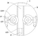
FIG. 6 is a partial enlarged view of A shown in FIG. 1;
fig. 7 is a partially enlarged view of B shown in fig. 3.
Reference numbers in the figures: 1. moving the vehicle body; 2. mounting a connecting frame; 201. a chute; 21. an electric push rod; 22. a collar; 3. a support frame; 31. collecting cotton nets; 32. a hydraulic cylinder; 33. a front cover plate; 34. a limiting plate; 4. a collection mechanism; 41. a main air duct; 42. a main adsorption cover; 43. a side air duct; 44. a side adsorption cover; 45. rotating the rod; 46. a roller; 47. turning over a plate; 5. a power mechanism; 51. an induced draft pipe; 52. an induced draft fan; 53. a rear cover plate; 6. a cotton scraping mechanism; 61. a rectangular frame; 62. a drive assembly; 621. a first lead screw; 622. a drive motor; 623. a drive block; 624. an auxiliary wheel; 63. a scraping assembly; 631. a support shaft; 632. a spur gear; 633. a rack plate; 634. a brush roller; 6341. a brush roll section; 64. a cutting assembly; 641. a second screw rod; 642. a servo motor; 643. a slider; 644. cutting the motor; 645. cutting the slices; 7. a hold-down mechanism; 71. a connecting rod; 72. a transmission rod; 73. pushing a plate; 731. a protrusion; 8. a filter screen; 9. and a brush.
Detailed Description
In order to make the objects, technical solutions and advantages of the present invention more apparent, the present invention is described in further detail below with reference to the accompanying drawings and embodiments. It should be understood that the specific embodiments described herein are merely illustrative of the invention and do not limit the invention.
Specific implementations of the present invention are described in detail below with reference to specific embodiments.
The first embodiment is as follows:
referring to fig. 1 to 7, an embodiment of the present invention provides a waste recycling device for cotton yarn production, including: the device comprises a movable vehicle body 1, a mounting connecting frame 2, a supporting frame 3, a collecting mechanism 4, a power mechanism 5 and a cotton scraping mechanism 6.
The top end of the movable trolley body 1 is welded with the mounting connection frame 2, the support frame 3 is installed in the middle of the mounting connection frame 2, electric push rods 21 are symmetrically installed on the rear side of the support frame 3 on the mounting connection frame 2, telescopic ends of the two electric push rods 21 are connected with a lantern ring 22 together, a latticed cotton collecting net 31 is embedded in the support frame 3, hydraulic cylinders 32 are symmetrically installed on the top end of the support frame 3, output shafts of the two hydraulic cylinders 32 are connected with a front cover plate 33 together, a collecting mechanism 4 used for adsorbing and collecting cotton yarn waste materials in a production workshop is fixedly installed on the front cover plate 33, a power mechanism 5 used for providing adsorption power for the collecting mechanism 4 is installed on the lantern ring 22, a cotton scraping mechanism 6 used for scraping cotton yarns on the cotton collecting net 31 is installed on the support frame 3, the cotton scraping mechanism 6 comprises a rectangular frame 61, a driving assembly 62, a scraping assembly 63 and a cutting assembly 64, the rectangular frame 61 is slidably installed on the support frame 3, the rectangular frame 61 wraps the cotton collecting net 31, the rectangular frame 61 is installed on the driving assembly 61 used for scraping cotton waste materials on the rectangular frame 31 and the lifting assembly 61 for driving assembly for driving the lifting assembly 3.
It should be noted that: during the use, through utilizing power unit 5 to provide absorption power for collecting mechanism 4, utilize and remove whole device of automobile body 1 drive and remove in the workshop, then carry out automatic absorption to cotton yarn growth waste material on ground and the wall in the workshop, until adsorbing to collecting in the cotton net 31, after collecting cotton net 31 and adsorbing certain cotton yarn waste material, stop to adsorb the recovery operation, promote front shroud 33 and collecting mechanism 4 through pneumatic cylinder 32 and keep away from collecting the cotton net 31, control electric putter 21 again and drive power unit 5 on the lantern ring 22 and keep away from collecting the cotton net 31, then start drive assembly 62, drive assembly 62 drives rectangular frame 61 and moves down along collecting the cotton net 31, in the removal process, drive scraping assembly 63 carries out work, thereby with the cotton yarn waste material of collecting on the cotton net 31, strike off, fall into installation link 2, when striking off the cotton yarn waste material of winding on assembly 63 and can't drop off, start cutting assembly 64 and cut off the cotton yarn waste material on the assembly 63 broken, fall into installation link 2 automatically, thereby realize high-efficient automatic recovery cotton yarn waste material.
In an embodiment of the present invention, please refer to fig. 1 and fig. 2, the collecting mechanism 4 includes a main air duct 41, a main adsorption hood 42, a side air duct 43 and a side adsorption hood 44, the main air duct 41 is fixedly mounted on the front cover plate 33, a downward end of the main air duct 41 is fixedly connected with the main adsorption hood 42, a plurality of adsorption cavities communicated with the main air duct 41 are uniformly formed at a bottom end of the main adsorption hood 42, a plurality of side air ducts 43 are symmetrically mounted on the front cover plate 33, and the side air ducts 43 located at the same side of the main air duct 41 are communicated with the side adsorption hood 44 through conduits.
It should be noted that: when collecting mechanism 4 and using, when power unit 5 and collection mechanism 4 are close to collection cotton twine 31, be in and adsorb the operation station, then power unit 5 provides the cotton yarn waste material power of absorption to collection mechanism 4, when removing automobile body 1 and drive whole device and remove in the workshop, main absorption cover 42 is with the automatic absorption of subaerial cotton yarn waste material, on main tuber pipe 41 inhales collection cotton twine 31, then side absorption cover 44 adsorbs the cotton fiber of loss in the environment in step, on inhaling collection cotton twine 31 through side tuber pipe 43, accomplish the collection of cotton yarn waste material.
In the embodiment: the dwang 45 is installed in the rotation in the absorption opening of side absorption cover 44, the both ends of dwang 45 all pass side absorption cover 44 and install gyro wheel 46, the cover is equipped with turns over board 47 on the lateral wall that dwang 45 is located side absorption cover 44, the lateral wall that turns over board 47 and side absorption cover 44's inside wall sliding connection, adsorb cover 44 at the removal in-process when the side like this, when being close to the wall, gyro wheel 46 contacts the wall, roll in step, thereby turn over board 47 and rotate, thereby scrape the scattering with wall and the interior cotton yarn waste material of side absorption cover 44, be convenient for in the side tuber pipe 43 of sucking.
In the embodiment of the present invention, referring to fig. 1, fig. 2 and fig. 3, the power mechanism 5 includes an induced duct 51, an induced draft fan 52 and a rear cover plate 53, the induced duct 51 is fixedly installed on the lantern ring 22, the induced draft fan 52 is embedded in the induced duct 51, an air inlet of the induced draft fan 52 faces one side of the cotton collecting net 31, and one side of the induced duct 51 close to the cotton collecting net 31 is fixedly installed with the rear cover plate 53 which is in sealing fit with the front cover plate 33.
It should be noted that: when power unit 5 uses, including back shroud 53 and front shroud 33 are close to each other with the parcel of collection cotton net 31, reuse the powerful draught fan 52 of prior art to provide the absorption power, then adsorb cotton yarn waste material.
In the present embodiment: the filter screen 8 is inlayed to the front end of back shroud 53, one side fixed mounting that rectangle frame 61 is close to back shroud 53 has brush 9, like this when back shroud 53 adsorbs the cotton yarn waste material, utilize filter screen 8 to filter the cotton fiber that passes collection cotton net 31, prevent in tiny cotton fiber is adsorbed into draught fan 52, cause draught fan 52 to damage, then when rectangle frame 61 removes the cotton yarn waste material of striking off collection cotton net 31, it scrapes the cotton yarn waste material on the filter screen 8 in step to drive brush 9, the realization is to the cleanness of filter screen 8, prevent its jam.
In an embodiment of the present invention, referring to fig. 1, fig. 2, fig. 6 and fig. 7, the driving assembly 62 includes first lead screws 621, driving motors 622, driving blocks 623 and auxiliary wheels 624, the first lead screws 621 are symmetrically installed on the supporting frame 3 and located at two sides of the cotton collecting net 31, the driving motors 622 for driving the first lead screws 621 to rotate are fixedly installed at the top end of the supporting frame 3, the two driving blocks 623 are respectively installed on the first lead screws 621 in a threaded manner, and both the two driving blocks 623 are fixedly connected to the rectangular frame 61, the auxiliary wheels 624 are rotatably installed on the driving blocks 623, the limiting plates 34 in contact with the auxiliary wheels 624 are symmetrically installed at two sides of the supporting frame 3 on the cotton collecting net 31, and the scraping assemblies 63 are installed on the limiting plates 34 and the rectangular frame 61.
The scraping assembly 63 comprises a supporting shaft 631, straight gears 632, rack plates 633 and brush rollers 634, two supporting shafts 631 are symmetrically mounted on a rectangular frame 61 and are connected with the rectangular frame 61 in a rotating mode, the straight gears 632 are symmetrically mounted on the two supporting shafts 631, the four rack plates 633 are mounted on the side walls of the two limiting plates 34 respectively, the rack plates 633 are meshed with the straight gears 632 on the same side, the two supporting shafts 631 are located between the two straight gears 632, the brush rollers 634 are connected with the brush rollers 634 in a fixed mode, the brush rollers 634 are composed of three brush roller sections 6341, and gaps for cutting the cutting assembly 64 are formed between the two adjacent brush roller sections 6341.
The cutting assembly 64 comprises two lead screw pairs 641, a servo motor 642, a sliding block 643, a cutting motor 644 and a cutting piece 645, the two lead screw pairs 641 are symmetrically installed on the rectangular frame 61 and are rotatably connected with the rectangular frame 61, the two servo motors 642 for driving the two lead screw pairs 641 to rotate are fixedly installed on the rectangular frame 61, the sliding block 643 is connected on each of the two lead screw pairs 641 in a threaded mode, the two sliding blocks 643 are slidably connected with the rectangular frame 61, the cutting motor 644 is fixedly installed on each of the two sliding blocks 643, and an output shaft of the cutting motor 644 is fixedly connected with the cutting piece 645.
It should be noted that: when the cotton scraping mechanism 6 is used, when a certain amount of cotton yarn waste is adsorbed on the cotton collecting net 31, the driving motor 622 is started to drive the first lead screw 621 to rotate, so as to drive the driving block 623 to move along the first lead screw 621, so as to drive the rectangular frame 61 to synchronously move, the auxiliary wheel 624 synchronously rolls along the limiting plate 34 during movement, when the rectangular frame 61 moves, the supporting shaft 631 on the rectangular frame 61 is driven to synchronously move, when the rack plate 633 is meshed with the straight gear 632 on the supporting shaft 631, the driving supporting shaft 631 drives the hair brush roll 634 to synchronously roll, so as to scrape the cotton yarn waste adsorbed on the cotton collecting net 31 from the cotton collecting net 31, when a large amount of cotton yarn waste wound on the hair brush roll 634 cannot fall off, the cutting motor 644 is started to drive the cutting blade to rotate, then the servo motor 642 is started to drive the second lead screw 643 to drive the cutting blade 643 to cut along a gap between the two hair brush roll joints 6341, until the cotton yarn waste wound on the hair brush roll 645 is cut, so that the cotton yarn waste can be conveniently separated from the hair brush roll 641, and the cotton yarn waste can be separated from the cotton collecting net 31, so as to be separated from the cotton collecting net 31.
In the present embodiment: the brush roller 634 adopts antistatic material to support, avoid friction to produce electrostatic adsorption, influence cotton yarn waste material and scrape from cotton collecting net 31, cutting piece 645 stretches into the clearance of two brush roll knuckles 6341, realize through the sliding distance that control rectangle frame 61 breaks away from behind the cotton collecting net 31 sliding down, promptly when sliding, straight-teeth gear 632 rotates with the meshing of rack board 633, adjust two different brush roll knuckles 6341's clearance and cut piece 645 and align, then cut, thereby cut into the three-section with the cotton yarn waste material that will twine on the brush roller 634, be convenient for it breaks away from.
Example two:
in the second embodiment, referring to fig. 1, 2 and 5, a pressing mechanism 7 is installed on the rectangular frame 61, the pressing mechanism 7 includes a connecting rod 71, a transmission rod 72 and a push plate 73, the four connecting rods 71 are respectively connected to the bottom ends of the rectangular frame 61, the bottom ends of the four connecting rods 71 are respectively hinged to the transmission rod 72, the two transmission rods 72 on the same side are fixedly connected to the push plate 73, and the push plate 73 is connected to the installation connecting frame 2 in a sliding manner.
It should be noted that: when the cotton yarn waste material of retrieving is hung by scraping cotton machine and is fallen in erection joint frame 2, rectangle frame 61 when rising resets, and synchronous pulling connecting rod 71 upwards displacement drives two push pedal 73 and is close to each other under the transmission of transfer line 72 to the cotton yarn waste material that falls into in erection joint frame 2 promotes the extrusion, thereby compresses tightly loose cotton yarn waste material, compresses tightly concentrated the transportation after being convenient for retrieve.
In the present embodiment: protruding 731 has been seted up to push pedal 73 both sides, and installation link 2 offers the spout 201 with protruding 731 adaptation to realize that push pedal 73 slides along spout 201, promote the extrusion to the yarn waste in the installation link 2.
A method for recovering cotton yarn production waste, which uses the cotton yarn production waste recovery device.
The method comprises the following specific steps:
1. collecting cotton yarn waste: the suction fan 52 of the power mechanism 5 is started to work to provide suction power for the collecting mechanism 4, then the movable vehicle body 1 is controlled to move, and the collecting mechanism 4 is used for sucking and collecting cotton yarn waste in a production workshop into the cotton collecting net 31;
2. scraping cotton yarn waste: when a certain amount of cotton yarn waste is adsorbed and collected on the cotton collecting net 31, under the condition that the cotton collecting net 31 is blocked, the adsorption capacity of the collecting mechanism 4 is reduced and the induced draft fan 52 generates stuffy sound in the induced draft pipe 51 (mainly judged by observing the adsorption capacity of the collecting mechanism 4 and the working rotation state of the induced draft fan 52 in the induced draft pipe 51), the collecting mechanism 4 and the power mechanism 5 are controlled to stop and keep away from the cotton collecting net 31, and then the cotton yarn waste on the cotton collecting net 31 is scraped off by the cotton scraping mechanism 6 and falls into the mounting connecting frame 2;
3. centralized extrusion and transportation; after scraping cotton yarn waste material that cotton mechanism 6 will collect on the cotton net 31 and scraping to installation link 2 in, after rectangle frame 61 rises repeatedly many times, drive hold-down mechanism 7 and will install the cotton yarn waste material in link 2 and compress tightly into the group after, with the cotton yarn waste material centralized transportation processing in link 2.
The above description is only an embodiment of the present invention, and not intended to limit the scope of the present invention, and all modifications of equivalent structures and equivalent processes, which are made by using the contents of the present specification and the accompanying drawings, or directly or indirectly applied to other related technical fields, are included in the scope of the present invention.
Claims (10)
1. A cotton yarn production waste recovery device includes:
the cotton collector comprises a movable vehicle body (1), wherein a mounting connecting frame (2) is welded at the top end of the movable vehicle body (1), a support frame (3) is installed in the middle of the mounting connecting frame (2), electric push rods (21) are symmetrically installed on the rear side of the support frame (3) on the mounting connecting frame (2), telescopic ends of the two electric push rods (21) are connected with a lantern ring (22) together, a latticed cotton collecting net (31) is embedded in the support frame (3), hydraulic cylinders (32) are symmetrically installed at the top end of the support frame (3), and output shafts of the two hydraulic cylinders (32) are connected with a front cover plate (33) together;
it is characterized by also comprising:
the collecting mechanism (4) is used for adsorbing and collecting cotton yarn waste in a production workshop, and the collecting mechanism (4) is fixedly arranged on the front cover plate (33);
the power mechanism (5) is used for providing adsorption power for the collecting mechanism (4), and the power mechanism (5) is arranged on the lantern ring (22);
scrape cotton machine construct (6), be used for scraping off the cotton yarn on collection cotton net (31) scrape cotton machine construct (6) and install on support frame (3), and scrape cotton machine construct (6) including rectangle frame (61), drive assembly (62), scrape subassembly (63) and cutting assembly (64), rectangle frame (61) slidable mounting is on support frame (3), and including rectangle frame (61) will collect cotton net (31) parcel, and installs on rectangle frame (61) and be used for scraping off subassembly (63) of the cotton yarn waste material on collection cotton net (31) and cutting assembly (64) that are used for cutting the cotton yarn waste material on scraping off subassembly (63) for drive rectangle frame (61) goes up and down at support frame (3) drive assembly (62) fixed mounting is on support frame (3).
2. The cotton yarn production waste recycling device according to claim 1, wherein the collecting mechanism (4) comprises a main air pipe (41), a main adsorption cover (42), a side air pipe (43) and a side adsorption cover (44), the main air pipe (41) is fixedly installed on the front cover plate (33), the downward end of the main air pipe (41) is fixedly connected with the main adsorption cover (42), a plurality of adsorption cavities communicated with the main air pipe (41) are uniformly formed in the bottom end of the main adsorption cover (42), the side air pipes (43) are symmetrically installed on the front cover plate (33), and the side air pipes (43) located on the same side of the main air pipe (41) are communicated with the side adsorption cover (44) through guide pipes.
3. The cotton yarn production waste recovery device according to claim 2, wherein a rotating rod (45) is rotatably installed in the adsorption port of the side adsorption cover (44), two ends of the rotating rod (45) penetrate through the side adsorption cover (44) and are provided with rollers (46), a turning plate (47) is sleeved on the side wall of the rotating rod (45) in the side adsorption cover (44), and the outer side wall of the turning plate (47) is in sliding connection with the inner side wall of the side adsorption cover (44).
4. The cotton yarn production waste recycling device according to claim 1, characterized in that the power mechanism (5) comprises an induced draft pipe (51), an induced draft fan (52) and a rear cover plate (53), the induced draft pipe (51) is fixedly installed on the lantern ring (22), the induced draft pipe (51) is embedded with the induced draft fan (52), the air inlet of the induced draft fan (52) faces one side of the cotton collecting net (31), and one side of the induced draft pipe (51) close to the cotton collecting net (31) is fixedly installed with the rear cover plate (53) in sealing fit with the front cover plate (33).
5. The cotton yarn production waste recycling device according to claim 4, wherein the front end of the rear cover plate (53) is embedded with a filter screen (8), and one side of the rectangular frame (61) close to the rear cover plate (53) is fixedly provided with a brush (9).
6. The cotton yarn production waste recovery device of claim 1, wherein the driving assembly (62) comprises a first screw rod (621), a driving motor (622), a driving block (623) and an auxiliary wheel (624), the first screw rod (621) is symmetrically installed on the support frame (3) and located on two sides of the cotton collecting net (31), the driving motor (622) is used for driving the two first screw rods (621) to rotate and is fixedly installed on the top end of the support frame (3), the driving block (623) is respectively installed on the two first screw rods (621) in a threaded manner, the two driving blocks (623) are fixedly connected with the rectangular frame (61), the auxiliary wheel (624) is rotatably installed on the driving block (623), the support frame (3) is located on two sides of the cotton collecting net (31) and is symmetrically installed on a limiting plate (34) in contact fit with the auxiliary wheel (624), and the scraping assembly (63) is installed on the limiting plate (34) and the rectangular frame (61).
7. The cotton yarn production waste recovery device according to claim 6, wherein the scraping component (63) comprises support shafts (631), straight gears (632), rack plates (633) and brush rollers (634), two support shafts (631) are symmetrically mounted on the rectangular frame (61) and rotatably connected with the rectangular frame (61), the two support shafts (631) are symmetrically mounted with the straight gears (632), four rack plates (633) are respectively mounted on the side walls of the two limit plates (34), the rack plates (633) are meshed with the straight gears (632) on the same side, and the brush rollers (634) are fixedly connected between the two straight gears (632) on the two support shafts (631);
the brush roller (634) consists of three brush roller sections (6341), and a gap for cutting the cutting assembly (64) is formed between every two adjacent brush roller sections (6341).
8. The cotton yarn production waste recycling device according to claim 7, wherein the cutting assembly (64) comprises two lead screws (641), a servo motor (642), a sliding block (643), a cutting motor (644) and a cutting piece (645), the two lead screws (641) are symmetrically arranged on the rectangular frame (61) and are rotatably connected with the rectangular frame (61), the two servo motors (642) for driving the two lead screws (641) to rotate are fixedly arranged on the rectangular frame (61), the sliding block (643) is in threaded connection with each of the two lead screws (641), the two sliding blocks (643) are in sliding connection with the rectangular frame (61), the cutting motor (644) is fixedly arranged on each of the two sliding blocks (643), and the cutting piece (645) is fixedly connected with an output shaft of the cutting motor (644).
9. The cotton yarn production waste recovery device according to claim 1, wherein a pressing mechanism (7) is installed on the rectangular frame (61), the pressing mechanism (7) comprises connecting rods (71), transmission rods (72) and push plates (73), four connecting rods (71) are respectively connected to the bottom ends of the rectangular frame (61), the bottom ends of the four connecting rods (71) are respectively hinged to the transmission rods (72), the two transmission rods (72) on the same side are fixedly connected with the push plates (73), and the push plates (73) are connected with the installation connecting frame (2) in a sliding mode.
10. A method for recovering cotton yarn production waste, characterized in that the cotton yarn production waste recovery apparatus according to any one of claims 1 to 9 is used.
Priority Applications (1)
| Application Number | Priority Date | Filing Date | Title |
|---|---|---|---|
| CN202211242135.XA CN115607045A (en) | 2022-10-11 | 2022-10-11 | Cotton yarn production waste recovery device and recovery method |
Applications Claiming Priority (1)
| Application Number | Priority Date | Filing Date | Title |
|---|---|---|---|
| CN202211242135.XA CN115607045A (en) | 2022-10-11 | 2022-10-11 | Cotton yarn production waste recovery device and recovery method |
Publications (1)
| Publication Number | Publication Date |
|---|---|
| CN115607045A true CN115607045A (en) | 2023-01-17 |
Family
ID=84862088
Family Applications (1)
| Application Number | Title | Priority Date | Filing Date |
|---|---|---|---|
| CN202211242135.XA Withdrawn CN115607045A (en) | 2022-10-11 | 2022-10-11 | Cotton yarn production waste recovery device and recovery method |
Country Status (1)
| Country | Link |
|---|---|
| CN (1) | CN115607045A (en) |
-
2022
- 2022-10-11 CN CN202211242135.XA patent/CN115607045A/en not_active Withdrawn
Similar Documents
| Publication | Publication Date | Title |
|---|---|---|
| CN212713900U (en) | Carding machine is used in quilt production | |
| CN209871970U (en) | Yarn production is with removing wadding device | |
| CN115354421B (en) | Spinning machine | |
| CN115607045A (en) | Cotton yarn production waste recovery device and recovery method | |
| CN213708592U (en) | Carding machine cleaning device | |
| CN216585362U (en) | A comb and parallel cotton fibers prior to spinning device | |
| CN214300526U (en) | High-efficiency roving frame lint cleaning device | |
| CN214142993U (en) | Dust collecting equipment is used in fabrics production | |
| CN211384353U (en) | Dust control device in organic cotton spinning | |
| CN217616496U (en) | Cleaning device for ring spinning technology weaving | |
| CN219861757U (en) | Fine hair clearing device for roving frame | |
| CN220846390U (en) | Impurity removing device for cotton carding processing | |
| CN220099342U (en) | Automatic dust removing mechanism of circular knitting machine | |
| CN221460626U (en) | Dust remover of semi-worsted carding machine | |
| CN214610825U (en) | Coiling mechanism is used in chemical fibre spinning production | |
| CN221581435U (en) | Curtain weaving dirt collection device | |
| CN215366135U (en) | Spinning frame for spinning production of bicomponent yarn | |
| CN221192681U (en) | Cloth surface dust collector for clothing weaving | |
| CN217052539U (en) | Fly frame fine hair cleaning device | |
| CN216663330U (en) | Do benefit to carding machine device that no static silver was combed | |
| CN219515283U (en) | Tobacco processing slivering machine | |
| CN218466016U (en) | Opener is used in non-woven fabrics production | |
| CN218756221U (en) | Carding machine faucet structure capable of preventing dust deposition | |
| CN218263185U (en) | Air purification device for textile processing | |
| CN219603809U (en) | Roving frame for spinning |
Legal Events
| Date | Code | Title | Description |
|---|---|---|---|
| PB01 | Publication | ||
| PB01 | Publication | ||
| SE01 | Entry into force of request for substantive examination | ||
| SE01 | Entry into force of request for substantive examination | ||
| WW01 | Invention patent application withdrawn after publication |
Application publication date: 20230117 |
|
| WW01 | Invention patent application withdrawn after publication |